

Samsung AQ24A2QC, AQ18A2QC, UQ24A2QC, UQ18A2QC Service Manual
ROOM AIR CONDITIONER
INDOOR UNIT
AQ24A2QC
AQ18A2QC
SERVICE
OUTDOOR UNIT
UQ24A2QC
UQ18A2QC
Manual
CONTENTSAIR CONDITIONER
1. Installation
2. Disassembly and Reassembly
3. Troubleshooting
4. Exploded Views and Parts List
5. Refrigerating Cycle Block Diagrams
6. Wiring Diagrams
7. Schematic Diagrams
E DB68-00276A(5)
1. Installation
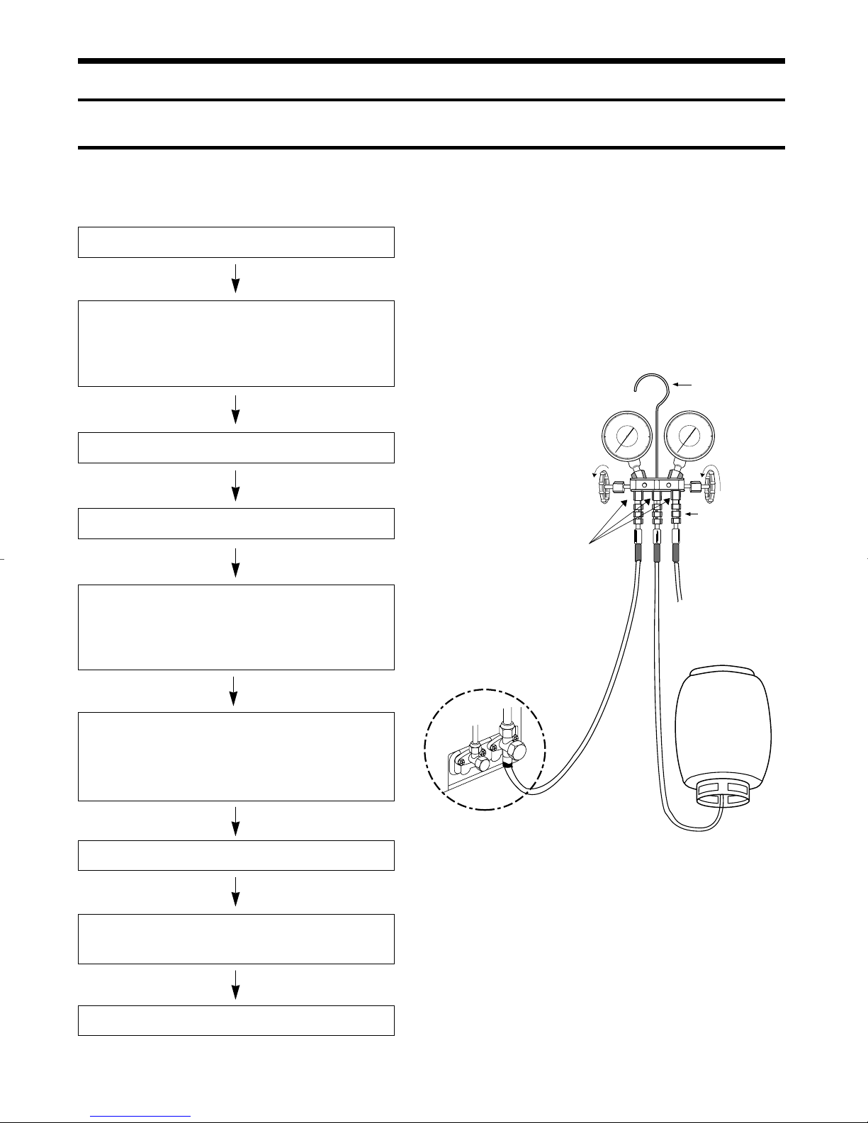
1-1 Refrigerant Refill Procedure
• Refill an air-conditioner with refrigerant when refrigerant has been leaked at installing or using
1. Purge air(for new installation only).
2. Turn the 3-way valve clockwise to close,
connect the pressure gauge(low
pressure side) to the service valve, and
open the 3-way valve again.
Suspension hook
3. Connect the tank to refill with Refrigerant
4. Set the unit to cool operation mode.
5. Check the pressure indicated by the pressure gauge(low
pressure side).
* Standard pressure is should be 4.5~5.5kg/cm
2
in a
reqular, high operation mode.
6. Open the refrigerant tank and fill with refrigerant until
the rated pressure is reached.
* It is recommended not to pour the refrigerant in too
quickly, but gradually while operating a pressure valve.
Compound
gauge
For mounting
other and of
hose when
not in use
High
pressure
gauge
Hand
wheel
Finger tight
fittings
Connected to
high pressure
side
Charging
line
R-22
7. Stop operation of the air conditioner.
8. Close the 3-way valve, disconnect the pressure gauge,
and open the 3-way valve again.
9. Close the cap of each valve.
1
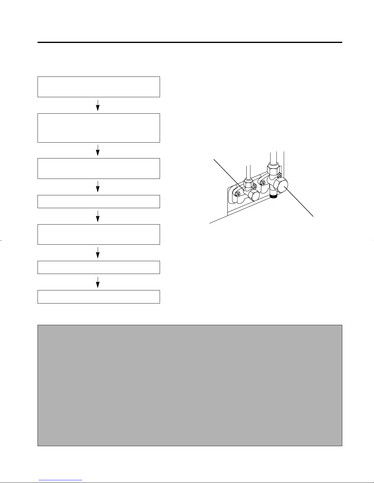
1-2 “Pump down” Procedure
• Pump down' shall be carried out when an evaporator is replaced or when the unit is relocated in
another area.
1. Remove the caps from the 2-way valve and the
3-way valve.
2. Turn the 3-way valve clockwise to close and
connect a pressure gauge(low pressure side) to
the service valve, and open the 3-way valve again.
2-Way Valve
3. Set the unit to cool operation mode.
(Check if the compressor is operating.)
4. Turn the 2-way valve clockwise to close.
5. When the pressure gauge indicates "0" turn the
3-way valve clockwise to close.
6. Stop operation of the air conditioner.
7. Close the cap of each valve.
Relocation of the air conditioner
• Refer to this procedure when the unit is
relocated.
1. Carry out the pump down procedure (refer
to the details of 'pump down').
2. Remove the power cable.
3. Disconnect the assembly cable from the
indoor and outdoor units.
4. Remove the flare nut connecting the indoor
unit and the pipe.
At this time, cover the pipe of the indoor
unit and the other pipe using a cap or vinyl
plug to avoid foreign material entering.
3-Way Valve
5. Disconnect the pipe connected to the outdoor unit.
At this time, cover the valve of the outdoor
unit and the other pipe using a cap or vinyl
plug to avoid foreign material entering.
6. Make sure you do not bend the connection
pipes in the middle and store together with
the cables.
7. Move the indoor and outdoor units to a new
locatioon.
8. Remove the mounting plate for the indoor
unit and move it to a new location.
2
2. Disassembly and Reassembly
Stop operation of the air conditioner and remove the power cable before repairing the unit.
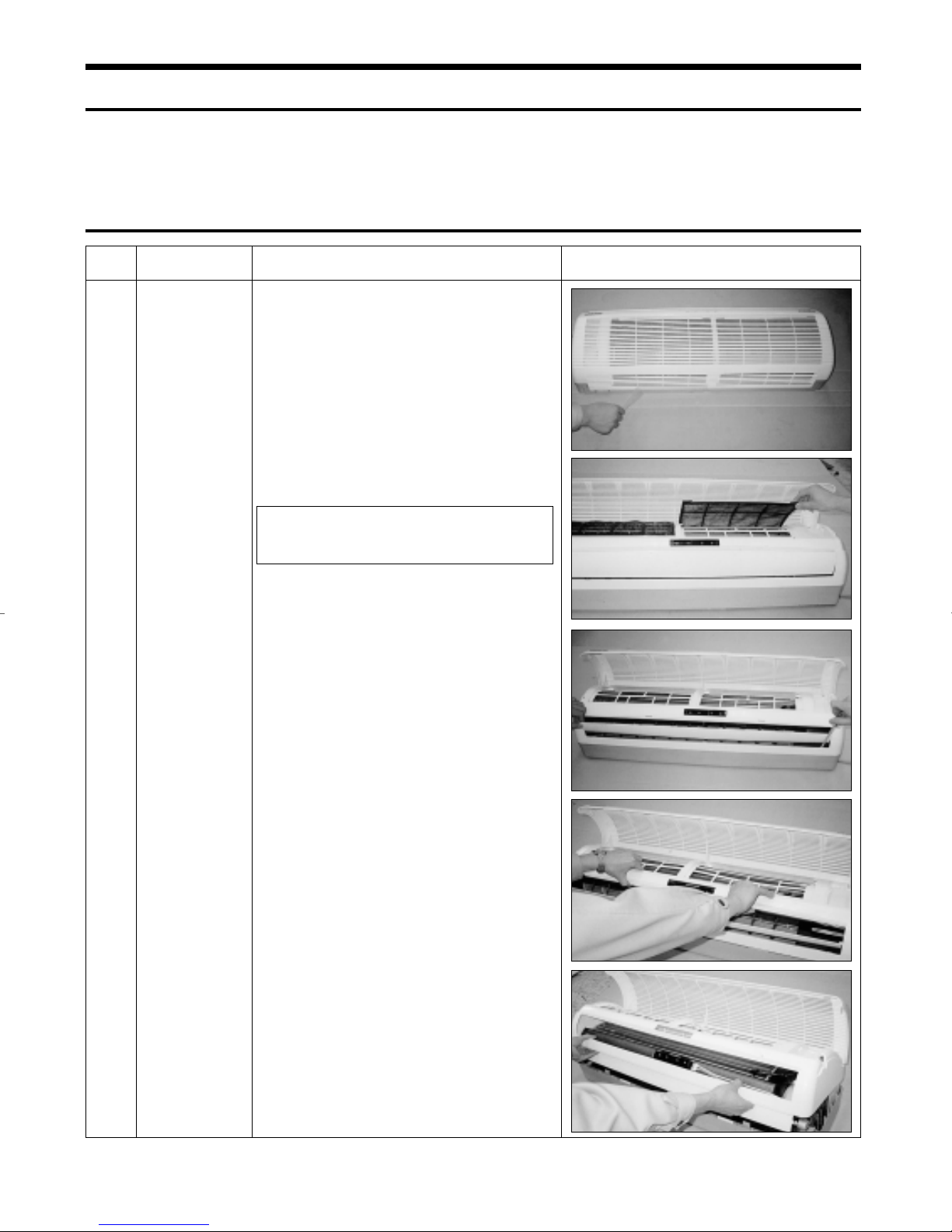
2-1 Indoor Unit
No Parts Procedure Remark
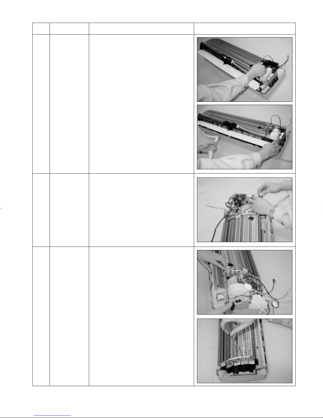
Front Grille1 1) Stop the air conditioner operation and block
the main power.
2) Seperate tape of front panel upper.
3) Contract the second finger to the left, and
right handle and pull to open the inlet grille.
4) Take the left and right filter out.
* Take the Deadorizing and Electrostatic filter out.
(ONLY “1” and “5” Series models)
5) Loosen one of the right fixing screw and
seperate the terminal cover.
6) Loosen two fixing screws of front grille.
7) Pull the upper left and right of discharge softly for the outside cover to be pulled out.
8) Pull softly the lower part of discharge and
push it up.
Caution;
Assemble the front panel and fix the
hooks of left and right.
3
No Parts Procedure Remark
2
3
Ass’y Tray Drain.
Electrical Parts
(Main PCB)
1) Do “1”, above.
Separate the drain hose from the extension drain
hose.
2) Take the display PCB out.
(Center of indoor unit)
3) Loosen two fixing screws of left and right
4) Pull tray drain out from the back body.
1) Do “1”, “2”, above
2) Take all the connector of PCB upper side out.
(Inclusion Power cord)
4
Heat Exchanger
3) Separate the outdoor unit connection wire from
the terminal block.
4) If pulling the Main PCB up. it will be taken out.
(Separate the TRANS hook. it before).
1) Do “1” and “2”, “3”, above
2) Loosen two fixing earth screws of right side.
3) Separate the connection pipe.
4) Separate the bush body at the upper side and
holder at the rearside.
5) Loosen the two fixing screws of left side.
6) Lifting the heat exchanger up a little to push the
up side for separation from the indoor unit.
4
No Parts Procedure Remark
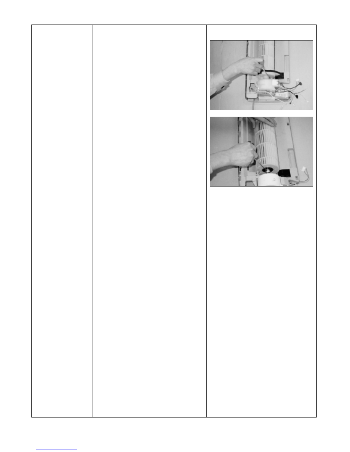
3 1) Do “1” “2” ”3” “4”, above.
Fan Motor and
Cross Fan
2) Loosen the fixing three screws and separate
the motor holder.
3) Loosen the fixing screw of fan motor.
(By use of M3 wrench)
4) Separate the fan motor from the fan.
5) Separate the fan from the left holder bearing.
5
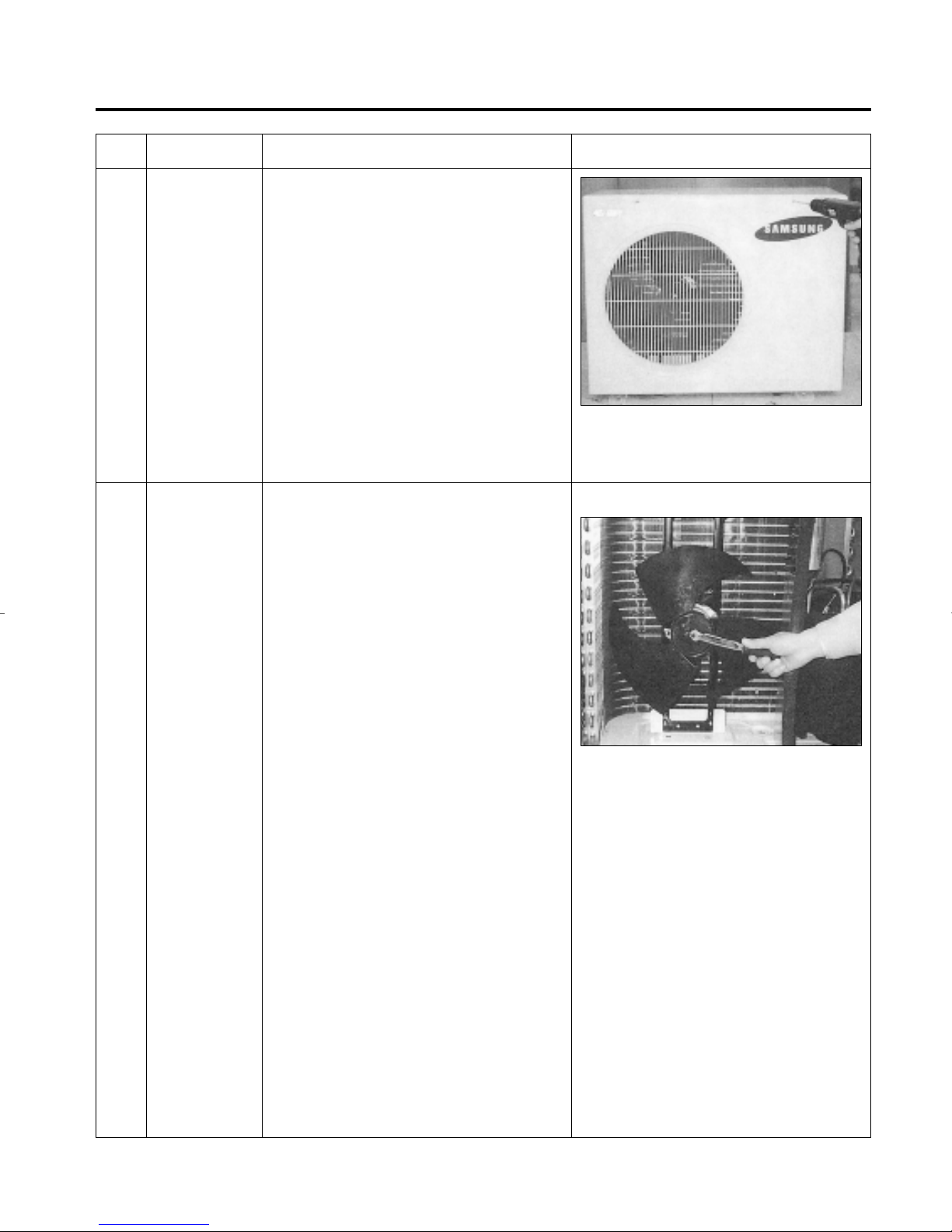
2-2 Outdoor Unit
No Parts Procedure Remark
1
2
Cabinet
Fan Motor &
Propeller Fan
1) Turn off the unit and remove the power cable
2) Remove the top cover.
3) Remove the control box cover.
4) Unplug the ass'y cable.
5) Remove the cabi-side.
6) Remove the cabi-front.
* When you assemble the parts, check if the
each parts and electric connectors are fixed
firmly.
1) Do Procedure 1 above.
2) Remove the nut flange.
(Turn to the right to remove as it is a left
turned screw)
3) Disassemble the propeller fan.
6
3. Troubleshooting
3-1 Items to be checked first
1) Is the voltage of the power correct?
The input voltage shall be the rating voltage ±10%.
The airconditioner may not operate properly if the voltage is out of this range.
2) Is the link cable linking the indoor unit and the outdoor unit linked properly?
The indoor unit and the outdoor unit shall be linked by 6 cables.
Check the terminals if the indoor unit and outdoor unit are properly linked by the same number of
cables.
Otherwise the airconditioner may not operate properly.
3) When a problem occurs due to the contents illustrated in the table below it is a symptom not
related to the malfunction of the airconditioner.
NO
1 The COOL operation indication LED (Green) blinks when a
power plug of the indoor unit is plugged in for the first time.
2 In a COOL operation mode, the compressor does not operate
at a room temperature higher than the setting temperature
that the INDOOR FAN should operate.
In a HEAT operation mode, the compressor does not operate
at a room temperature lower than the setting temperature
that indoor fan should operate.
3 Fan speed setting is not allowed in AUTO or DRY mode.
4 Compressor stops operation intermittently in DRY mode.
5 Compressor of the outdoor unit is operating although it is
turned off in a HEAT mode.
6 Timer LED only of the indoor unit lights up and the
air conditioner does not operate.
7 The compressor and indoor fan stop intermittently in HEAT
mode.
8 Indoor fan and outdoor fan stop operation intermittently in
a HEAT mode.
9 The compressor stops intermittently in a COOL mode or DRY
mode, and fan speed of the indoor unit decreases.
Operation of air conditioner
Explanation
It indicates power is on. The LED stops blinking if the operation
ON/OFF button on the remote control unit is pushed.
In happens after a delay of 3 minutes when the compressor is
reoperated. The same phenomenon occurs when a power is on.
As a phenomenon that the compressor is reoperated after a delay
of 3 minutes, the indoor fan is adjusted automatically with
reference to a temperature of the air blew
The speed of the indoor fan is set to LL in DRY mode.
Fan speed is 5 steps is selected automatically in AUTO mode.
Compressor operation is controlled automatically in DRY mode
depending on the room temperature and humidity.
When the unit is turned off while de-ice is activated, the
compressor continues operation for up to 9 minutes (maximum)
until the deice is completed.
Timer is being activated and the unit is in ready mode.
The unit operates normally if the timer operation is cancelled.
The compressor and indoor fan stop intermittently if room
temperature exceeds a setting temperature in order to protect the
compressor from overheated air in a HEAT mode.
The compressor operates in a reverse cycle to remove exterior ice
in a HEAT mode, and indoor fan and outdoor fan do not operate
intermittently for within 20% of the total heater operation
The compressor stops intermittently or the fan speed of the indoor
unit decreases to prevent inside/outside air frozen depending on
the inside/outside air temperature.
4) Indoor unit observes operation condition of the air conditioner, and displays self diagnosis details
on the display panel.
NO
1 Operating LED blinking (1Hz)
2 TIMER LED blinking (1Hz)
3 OPERATING and TIMER LED blinking (1Hz)
4 FAN LED blinking (1Hz)
Display
Self Diagnosis
Restore from power failure (input initial power)
Indoor unit Room sensor Error (open or short)
Indoor unit heat exchanger temperature sensor Error (open or short)
Indoor fan malfunctioning (for spead is Below 38Orpm)
7
3-2 Fault Diagnosis by Symptom
3-2-1 No Power(completely dead)-Initial diagnosis
1) Checklist :
(1) Is input voltage normal? (rating voltage ±10% range)
(2) Is AC power linked correctly?
(3) Are connections between primary side, secondary side of the power transformer and PCB good.
(4) Is output voltage of DC regulator IC KA7812 (IC01) normal? (11VDC-12.5VDC)
(5) Is output voltage of DC regulator IC KA7805 (IC02) normal? (4.5VDC-5.5VDC)
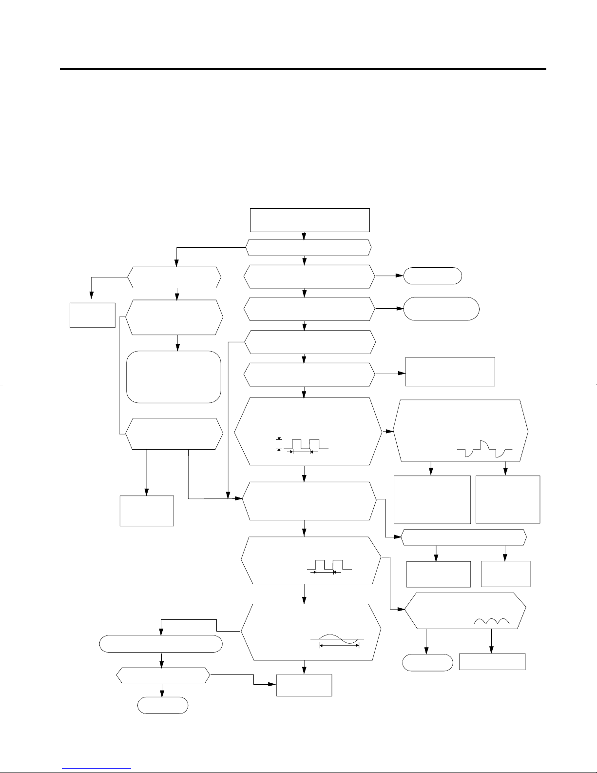
2) Troubleshooting procedure
Remove power cord and plug in again
in approx. 5 seconds
YES
Replace PCB
display
Is DC voltage of PCB
display normal?
NO
Is the rating voltage ±10%
range applied to the
primary side of the power
transformer?
NO
•Check linkage between
power cord and
terminal tap
•Check fuse
Is 14~18VAC appear in
the secondary side of the
power transformer?
NO
Replace power
transformer
NO
YES
Is operation lamp blinking?
Does operation start when
run/stop button on the remote
controller unit pushed?
Is transmission display of the remote
controller unit blinking?
Is "beep"sound heard from the main
NO
Is DC voltage of the PCB module
Are voltages of #59 (compressor),
#48(4 way valve) and #58 (outdoor fan)
of the micom normal?; 5VDC
Is voltage of #1 (indoor fan) of the
DC5V
Is voltage at #32 terminal of the Micom normal?
Is voltage at #64 terminal of the Micom normal?
Is voltage at #25 terminal of the
YES
NO
YES
unit?
YES
normal?
YES
micom normal?
10ms
NO
; 0VDC
; 5VDC
YES
micom normal?
YES
NO
NO
YES
NO
Normal
Refer to remote control
unit fault diagnosis
Replace PCB
module.
Are voltages at RY71(Compressor)
RY73(4-way valve) and SY72(outdoor fan)
normal?; DC12V
Is voltage at SS71(indoor fan)
YES
Check connections
compressor 4-way
valve, outdoor fan and
indoor fan.
Is output voltage of ICO2 normal?(DC5V)
YES
NO
Replace
RY71, RY73,
RY72 and
SS71
NO
Replace resonator (X501)
Is operation normal?
YES
OK
8
NO
NO
10ms
YES
Are voltage at #30 and #31 of the
micom normal?
100ns
YES
Replace
micom
NO
Check PCB pattern.
Replace main PCB.
Is voltage output terminal of
D101~D105(IN4007) normal?
YES
OK
Replace IN4007
Replace ICO2
NO
 Loading...