

Samsung AQ09A5(6)MAF, AQ12AA(B)MCF, UQ09A5(6)MAF, UQ12AA(B)MCF Service Manual
Manual
SERVICE
SPLIT TYPE AIR CONDITIONER
Indoor Unit
AQ09A5(6)MAF
AQ12AA(B)MCF
Outdoor Unit
UQ09A5(6)MAF
UQ12AA(B)MCF
E DB98-15777A(1)
Safety Precautions
The following safety precautions must be taken when using your air conditioner.
WARNING
DURING OPERATION
Risk of electric shock. • Can cause injury or death. • Disconnect all remote electric
power supplies before servicing, installing or cleaning. • This must be done by the
manufacturer or its service agent or a similar qualified person in order to avoid a
hazard.
◆ Users of this product are cautioned not to attempt repair of this product at
their own discretion. Instead, they are requested to directly contact a
designated service center or the outlet at which the product was
purchased.
◆ Never spill any kind of liquid into the unit. Should this happen, unplug
or main switch off the unit and contact an authorized service center.
◆ Do not insert anything between the air outlet blades because the inner
fan may be damaged and could cause injury. Keep children away from
the unit.
◆ Do not place any obstacles in front of the unit.
◆ Do not spray liquid of any kind into the indoor unit. Should this happen,
switch off the breaker used for your air conditioner and contact your
installation specialist.
◆ Make sure that the unit is correctly ventilated at all times:
Do not place clothing or other materials over it.
◆ If the wireless remote control will not be used for a long time, remove the
batteries. (If applicable)
◆ When using a wireless remote control, the distance should not be more
than 23ft(7m) from the air conditioner. (If applicable)
D
ISPOSING OF THE UNIT
OTHERS
2
◆ Before throwing out the device, it is necessary to pull back the battery cells
and get rid of them safely for recycling reasons.
◆ When you need to dispose of the unit, consult your dealer. If pipes are
removed incorrectly, refrigerant may blow out and come into contact with
your skin, causing injury. Releasing refrigerant into the atmosphere also
damages the environments.
◆ Please recycle or dispose of the packaging material for this product in an
environmentally responsible manner.
◆ Never store or ship the air conditioner upside down or sideways to avoid
damage to the compressor.
◆ The appliance is not intended for use by young children or infirm
persons without supervision: Young children should be supervised to
ensure that they do not play with the appliance.
◆ Max current is measured according to IEC standard for safety and
current is measured according to ISO standard for energy efficiency.
Contents
Ι
DISASSEMBLE AND REASSEMBLE
1. Indoor unit
2. Outdoor unit
ΙΙ
SET UP THE OPTION CODE
ΙΙΙ
TROUBLESHOOTING
1. Items to be checked first
2. Abnormal diagnosis by symptom
ΙΛ
ASSEMBLY DRAWING AND PART’S LIST
1. Indoor unit
2. Outdoor unit
3. Assembly control in
4. Assembly control out
Λ
REFRIGERATING CYCLE BLOCK DIAGRAM
Λ
Ι
P
ERFORMANCE CURVE
ΛΙΙ
WIRING DIAGRAM
1. Indoor unit
2. Outdoor unit
ΛΙΙΙ
SCHEMATIC DIAGRAM
1. Indoor unit
2. Outdoor unit
4
6
10
13
14
22
24
28
30
32
33
39
40
42
43
SPLIT TYPE
AIR CONDITIONER
3
Ι
Disassemble and reassemble
Stop operation of the air conditioner and remove the power cable before repairing the unit.
1 Indoor unit
If you disassemble the heat exchanger, you must pump down at first.
No. Part Procedure Remark
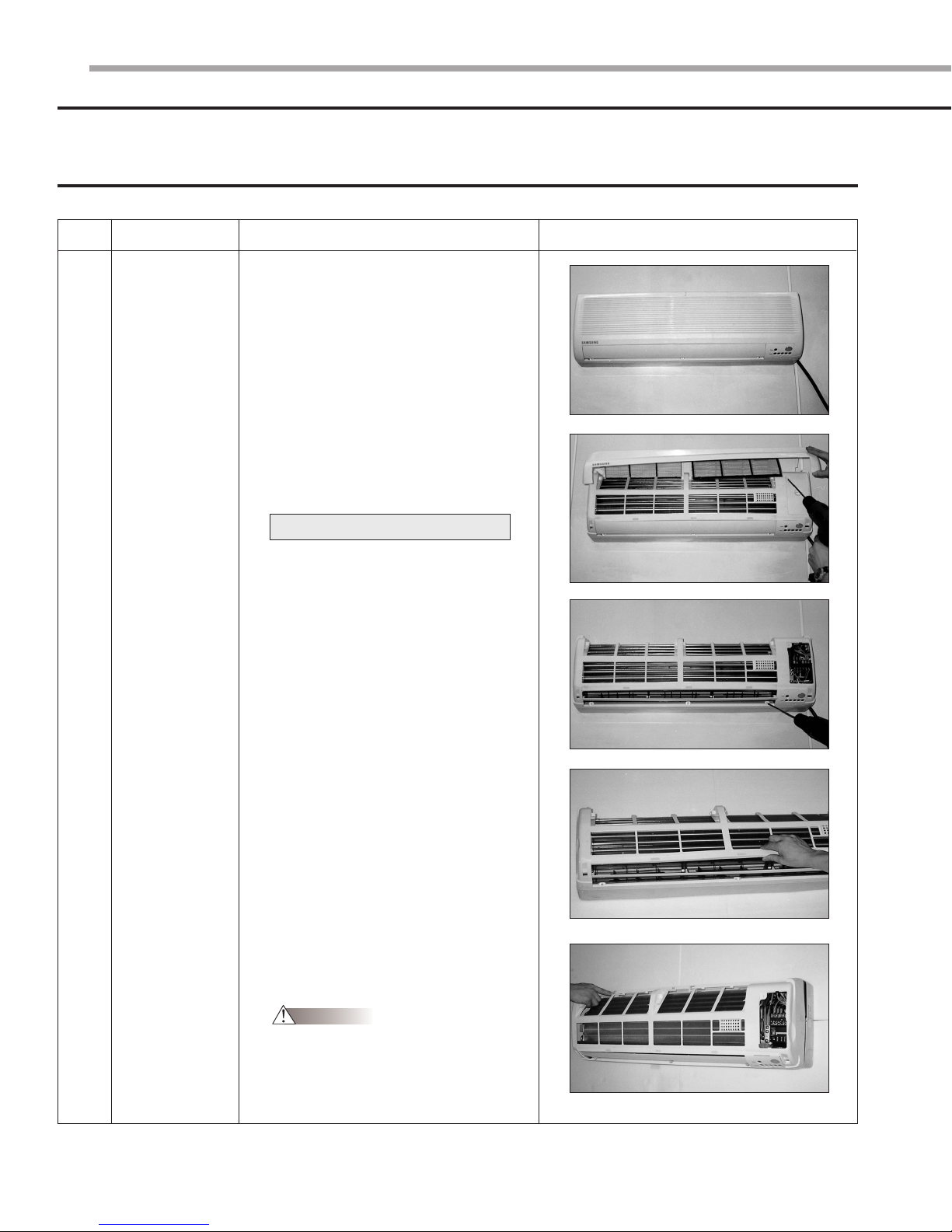
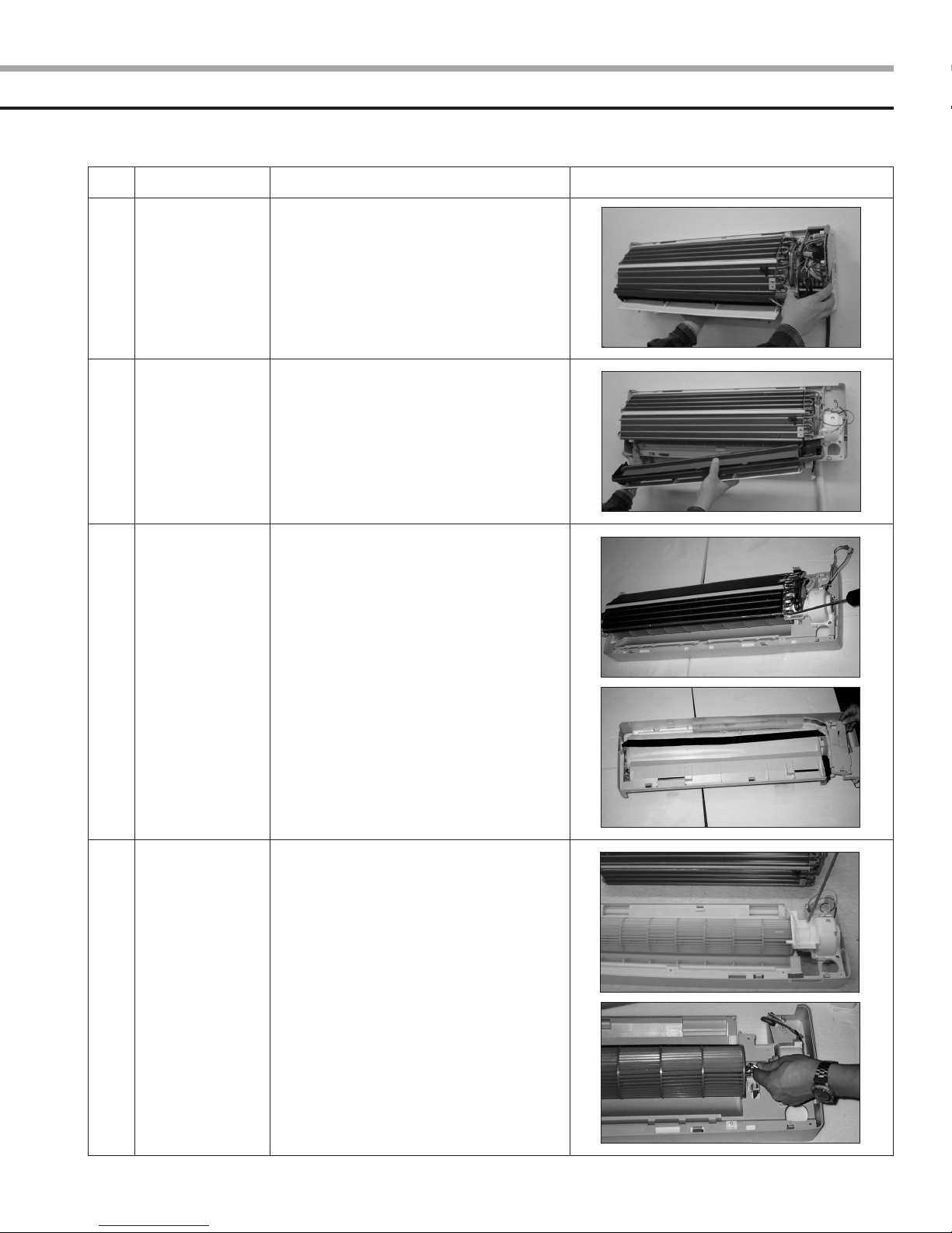
1
Front Panel
1) Stop the operation of the air conditioner
and block the main power.
2) Separate the tape from the front panel.
3) Contract the second finger to the left,
and right handle. And pull the inlet grille
to open.
4) Take the left and right filter out.
*Taking off the deodorizing filter.
5) Loosen one of the right screw and
separate the terminal cover.
6) Loosen three screws of front panel.
7) Pull the upper left, center and right of
discharge softly so that the outside cover
is pulled out.
8) Pull softly the lower part of discharge and
push it up.
Caution
Assemble the front panel and fix the
hooks of left, center and right.
4
No.
Part
Procedure Remark
2
3
4
Electrical
Parts
(Main PCB)
Assembly Tray
Drain
Heat
Exchanger
1) Take all the connector of PCB
on the upper part. (Included Power cord)
2) Separate the outdoor unit connection
wire from the terminal block.
3) If you pull out the main PCB up, it will be
taken out.
1) Separate the drain hose from the
extension drain hose.
2) Pull tray drain out from the back body.
1) Loosen two ground screws at the
right side.
2) Separate the connection pipe.
3) Separate the holder pipe at the rear side.
4) Loosen three screws at the right and
left side.
5) Lift the heat exchanger up a little to push
the upper side to separate it from the
indoor unit.
5
Fan Motor and
Cross Fan
1) Loosen two screws and separate the
motor holder.
2) Loosen the screw of fan motor.
(By use of M3 wrench)
3) Separate the fan motor from the fan.
4) Separate the fan from the left holder
bearing.
5
Ι
Disassemble and reassemble (cont’d)
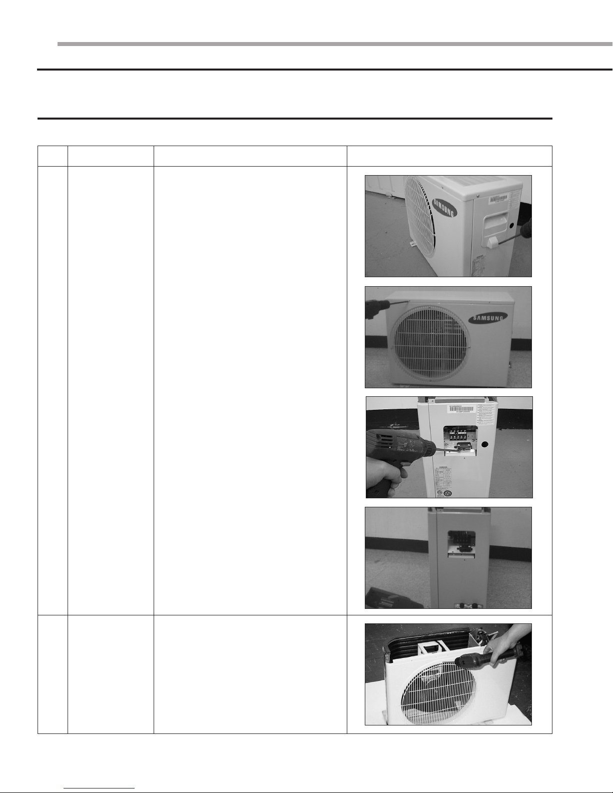
2 Outdoor unit
■ UQ09A5(6)MAF
No. Part Procedure Remark
Common Work
1
1) Loosen screws and separate the cover
E-part.
2) Separate the connection wire from the
terminal block.
3) Loosen five screws and separate the
upper cabinet.
4) Loosen a screw of the control box.
5) Loosen nine screws and separate the
side cabinet.
2
Fan Motor
1) Loosen four screws and separate
Guard Fan from the front cabinet.
6
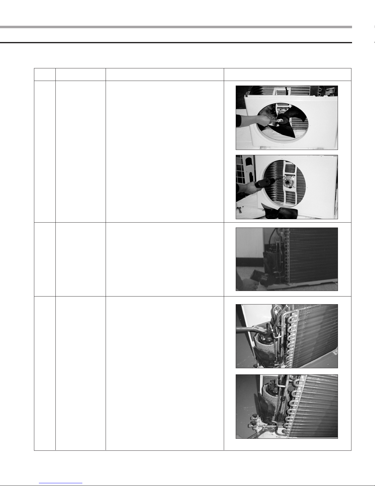
No. Part Procedure Remark
2) Remove the nut flange
(Turn to the clockwise).
3) Separate the fan.
4) Loosen four screws to separate the motor.
3
4
Heat
Exchanger
Compressor
1) Release the refrigerant.
2) Loosen two screws of left and right side.
3) Disassemble the inlet and outlet pipe by
welding.
4) Separate the heat exchanger.
1) Release the refrigerant.
2) Loosen the nut on the terminal cover
and open the terminal cover.
3) Separate the OLP and the compressor
wire.
4) Disassemble the inlet and outlet pipe
of compressor by welding.
5) Disassemble the inlet and outlet pipe
of condenser by welding
6) Loosen three bolts of the lower part.
7) Separate the compressor.
7

Ι
Disassemble and reassemble (cont’d)
■ UQ12AA(B)MCF
No. Part Procedure Remark
1
Common Work
1) Loosen a screw and separate the cover
E-part.
2) Separate the connection wire from the
terminal block.
3) Loosen thirteen screws and separate
the front cabinet.
4) Loosen a screw of the control box.
5) Loosen four screws and separate the
side cabinet.
8
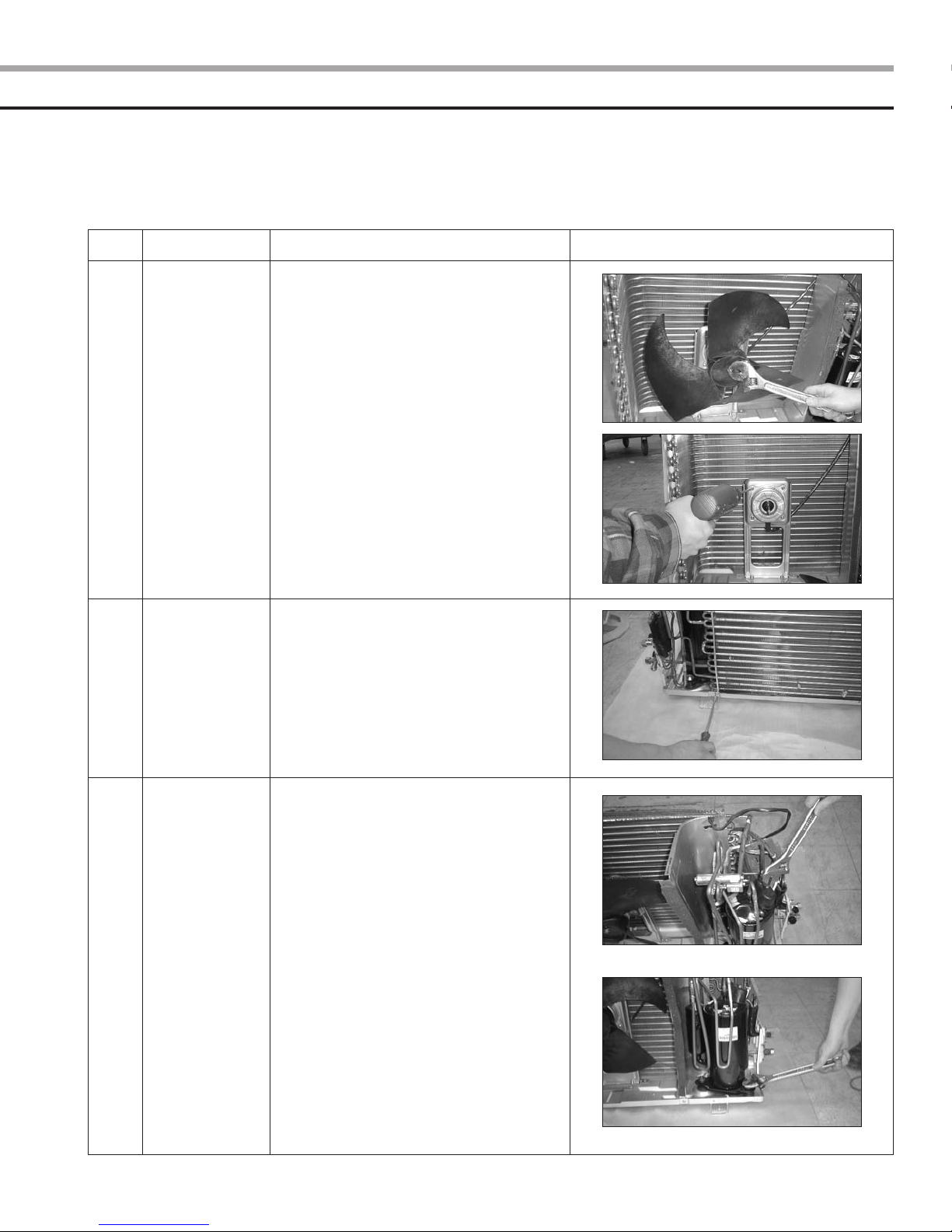
No. Part Procedure Remark
2
3
Fan and Motor
Heat Exchanger
1) Remove the nut flange
(Turn to the clockwise).
2) Separate the fan.
3) Loosen four screws to separate the motor.
1) Release the refrigerant.
2) Loosen screws of left and right side.
3) Disassemble the inlet and outlet pipe by
welding.
4) Separate the heat exchanger.
4
Compressor
1) Release the refrigerant.
2) Open the terminal cover of compressor
and unscrew the connection terminal.
3) Separate the OLP and the compressor
wire.
4) Disassemble the inlet and outlet pipe of
compressor by welding.
5) Loosen three bolts of the lower part.
6) Separate the compressor.
9
ΙΙ
Set up the option code
The method for setting up the model option with the remote control
◆ It is necessary to set up option codes after replacing the main PCB with service parts.
Make sure that you can set up option codes of the remote control after replacing the main PBA.
Otherwise, the unit won’t be working properly and all LED lamps on display will be flickering.
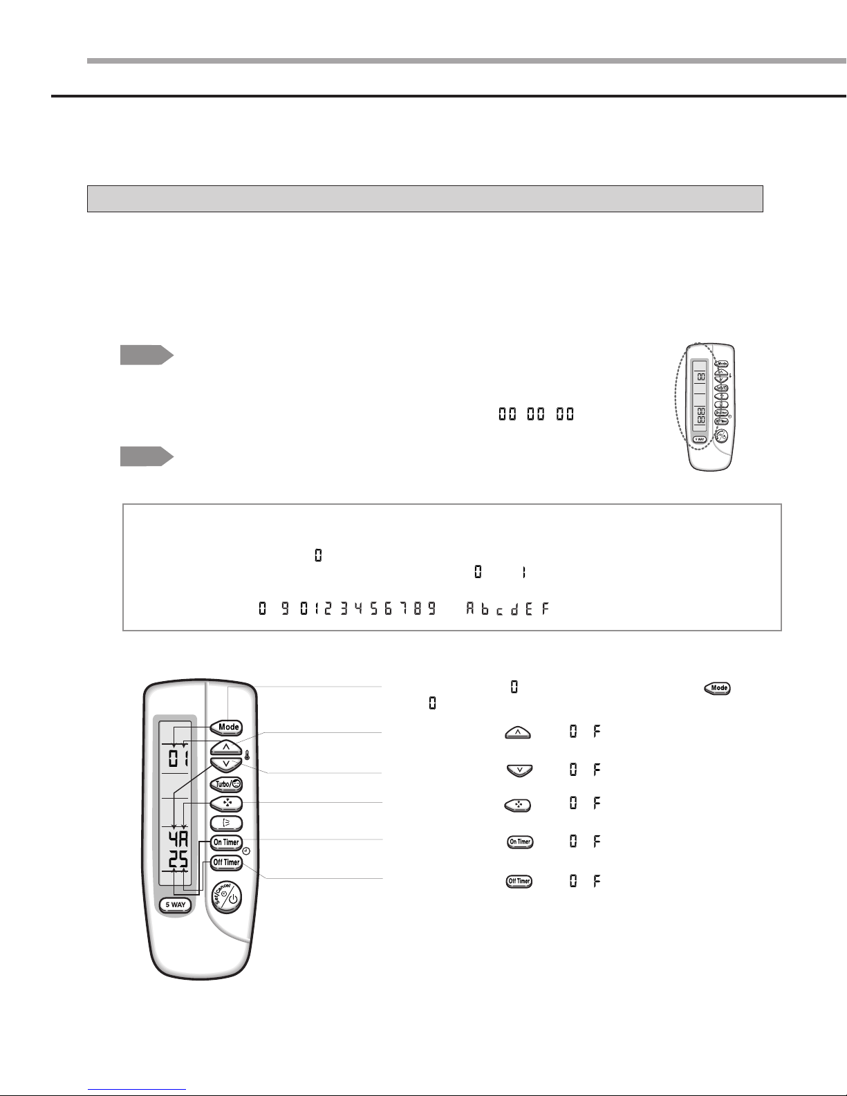
Step 1
Step 2
NNNNoooottttee
Preparing for the remote control to the main PCB option set.
1. Remove the battery from the remote control.
2. Press the temperature button simultaneously and insert the battery again.
3. Make sure the remote control display shown as .
Preparing for the remote control option set.
ee
In case that the wrong letter has been selected; continue to press the button until the
correct letter appears.
1. If the number “ ”appears on the display, proceed to the second stage.
2. Every time you press the 1) and 7) button, “ ” and “ ” continue to appear.
3. Every time you press the 2), 3), 4), 5), 6), 8), 9), 10), 11), 12) button, the number increases
from ~ ( , , , , , , , , , ) and , , , , , in order.
1) If the first number is , it is correct. Otherwise, press the button
until appears.
2) When pressing the button ~ on the display, select one of them.
10
3) When pressing the button ~ on the display, select one of them.
4) When pressing the button ~ on the display, select one of them.
5) When pressing the button ~ on the display, select one of them.
6) When pressing the button ~ on the display, select one of them.
7) If the first number is , it is correct. Otherwise, press the button
until appears.
8) When pressing the button ~ on the display, select one of them.
9) When pressing the button ~ on the display, select one of them.
10) When pressing the button ~ on the display, select one of them.
11) When pressing the button ~ on the display, select one of them.
12) When pressing the button ~ on the display, select one of them.
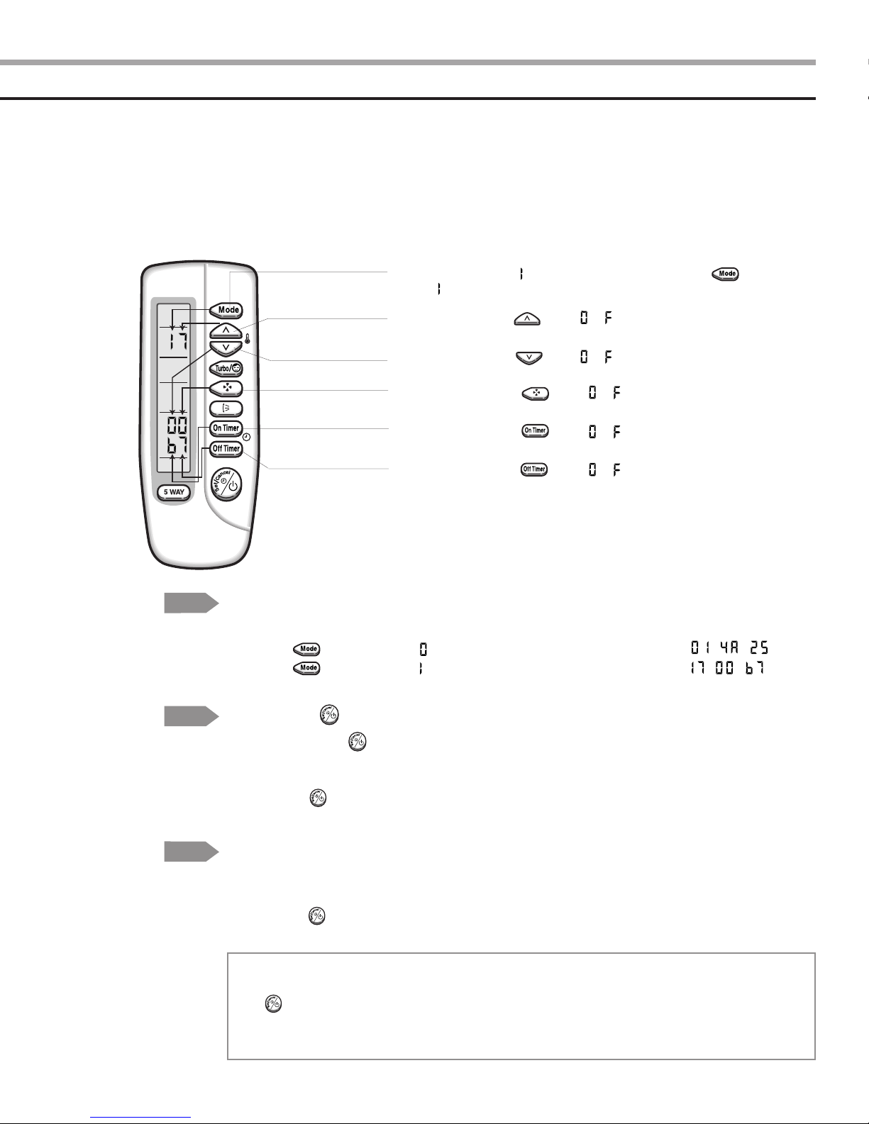
Step 3
Step 4
Step 5
NNNNoooottttee
Reconfirming the option set after completing
Example : 014A25-1700b7
Press the button for the “ ” mode and the display will be shown as .
Press the button for the “ ” mode and the display will be shown as .
Pressing the (On/Off)button
When pressing the (On/Off)button in the direction of the remote control for unit,
it sounds beep or ringing and the first LED lamp on the left side is flickering at the
same time, then the input option is completed. If it doesn’t sound ringing, try again by
pressing the (On/Off)button.
Testing the unit
1 Remove the battery from the remote control.
2. Insert the battery into the remote control.
3. Press the (On/Off)button in the direction of the remote control for set.
Error mode
ee
1. If all lamps of the indoor units are flickering, plug out and in again and press the
(On/Off)button again.
2. If the unit doesn’t work properly or all lamps are continuously flickering after setting the option
code, check that the option code is set properly for its own model.
11
ΙΙ
Set up the option code(cont’d)
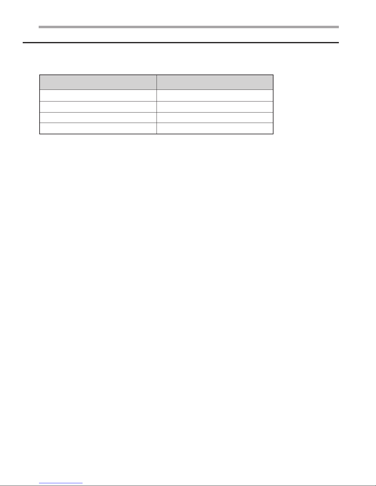
Table of the option code
Model
AQ09A5MAF
AQ09A6MAF
AQ12AAMCF
AQ12ABMCF
Option code
016A25-1700Fb
006A25-1700Fb
017227-170340
007227-170340
12
ΙΙΙ
Troubleshooting
1 Items to be checked first
1) The input voltage should be voltage rating within ±10% range.
The air conditioner may not operate properly if the voltage is out of this range.
2) Is the connection cable linking the indoor unit and the outdoor unit properly?
The indoor unit and the outdoor unit shall be linked by six cables.
Check the terminals if the indoor unit and outdoor unit are properly linked by the same number of cables.
Otherwise the air conditioner may not operate properly.
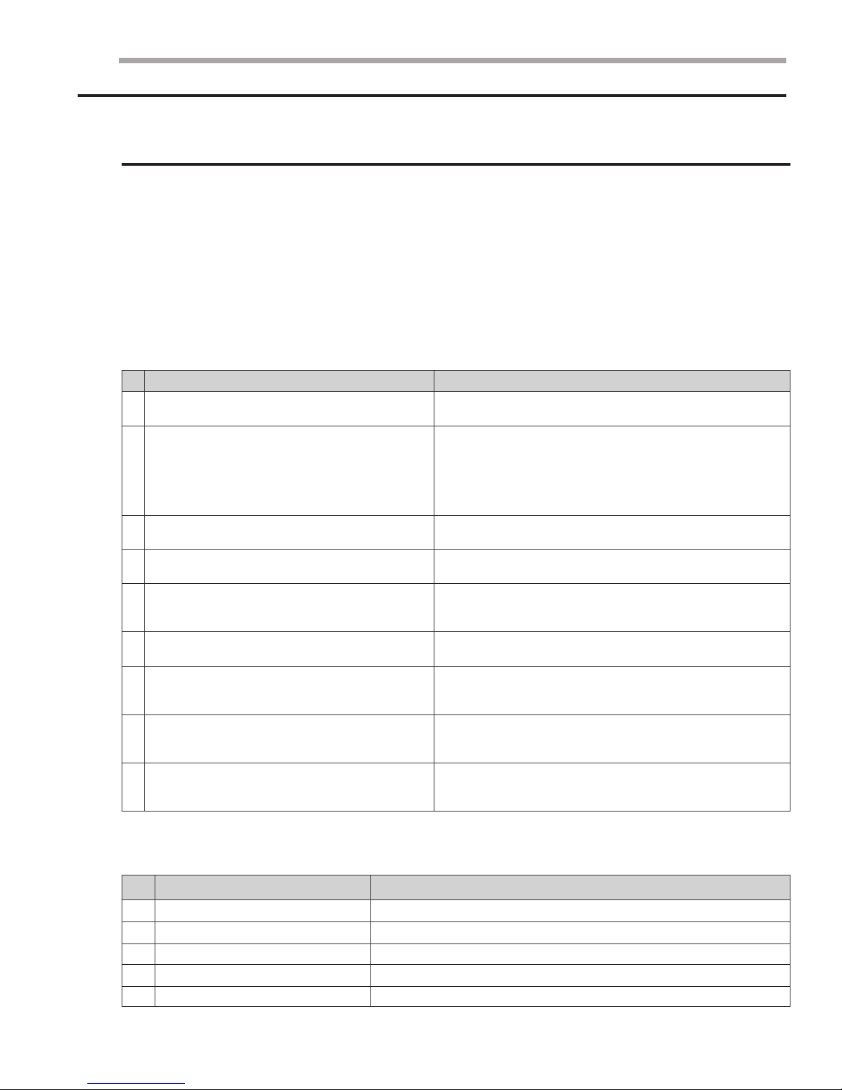
3) When a problem occurs due to the contents illustrated in the table below it is a symptom not related to
the malfunction of the air conditioner.
No.
The STD operation indicator, LED blinks when a
1
power plug of the indoor unit is plugged in at first.
In the Cool mode, the compressor does not operate
at a room temperature higher than the setting
temperature while the indoor fan operates.
2
In the Heat mode, the compressor does not operate
at a room temperature lower than the setting
temperature that the indoor fan should operate.
The Fan speed is not allowed in the Auto or
3
Dry mode.
Compressor stops operating intermittently
4
in the Dry mode.
Compressor of the outdoor unit is operating
although it is turned off in a Heat mode.
5
Only timer LED of the indoor unit lights up and the
6
air conditioner does not operate.
The compressor and indoor fan stop intermittently
in the Heat mode.
7
Indoor fan and outdoor fan stop operating
intermittently in the Heat mode.
8
The compressor stops intermittently in the Cool
mode or Dry mode and the fan speed of the indoor
9
unit decreases.
Operation of air conditioner
Explanation
It indicates power is on. The LED stops blinking if the
operation On/Off button on the remote control is pushed.
It happens after three minutes when the compressor is
reoperated. The same phenomenon occurs when a power
is on. As a phenomenon that the compressor is reoperated after
three minutes, the indoor fan is adjusted automatically with
reference to a temperature of the air.
The speed of the indoor fan is set to LL in the Dry mode. The Fan
speed is five steps are selected automatically in the Auto mode.
Compressor operation is controlled automatically in the Dry
mode depending on the room temperature and humidity.
When the unit is turned off while de-ice is activated,
the compressor continues operating for up to 9 minutes
(maximum) until the deice is completed.
The Timer is being activated and the unit is in the ready mode.
The unit operates normally if the timer operation is cancelled.
The compressor and indoor fan stop intermittently if room
temperature exceeds a setting temperature in order to protect
the compressor from overheated air in a HEAT mode.
The compressor operates in a reverse cycle to remove exterior
ice in the Heat mode, and indoor fan and outdoor fan do not
operate intermittently for within 20% of the total heater operation
The compressor stops intermittently or the fan speed of the
indoor unit decreases to prevent inside/outside air from
freezing depending on the inside/outside air temperature.
4) Indoor unit observes operation condition of the air conditioner, and displays self diagnosis details
on the display panel.
No.
1
STD LED blinking (1Hz)
2
TIMER LED blinking (1Hz)
3
STD and TIMER LED blinking (1Hz)
4
NATURE LED blinking (1Hz)
ALL LED blinking (1Hz)
5
Display
Self Diagnosis
Restore from power failure (input initial power)
Indoor unit Room sensor Error (open or short)
Indoor unit heat exchanger temperature sensor Error (open or short)
Indoor fan malfunctioning (for speed is below 450rpm)
Option Error
13
ΙΙΙ
Troubleshooting (cont’d)
2 Abnormal diagnosis by symptom
■ AQ09A5(6)MAF
14
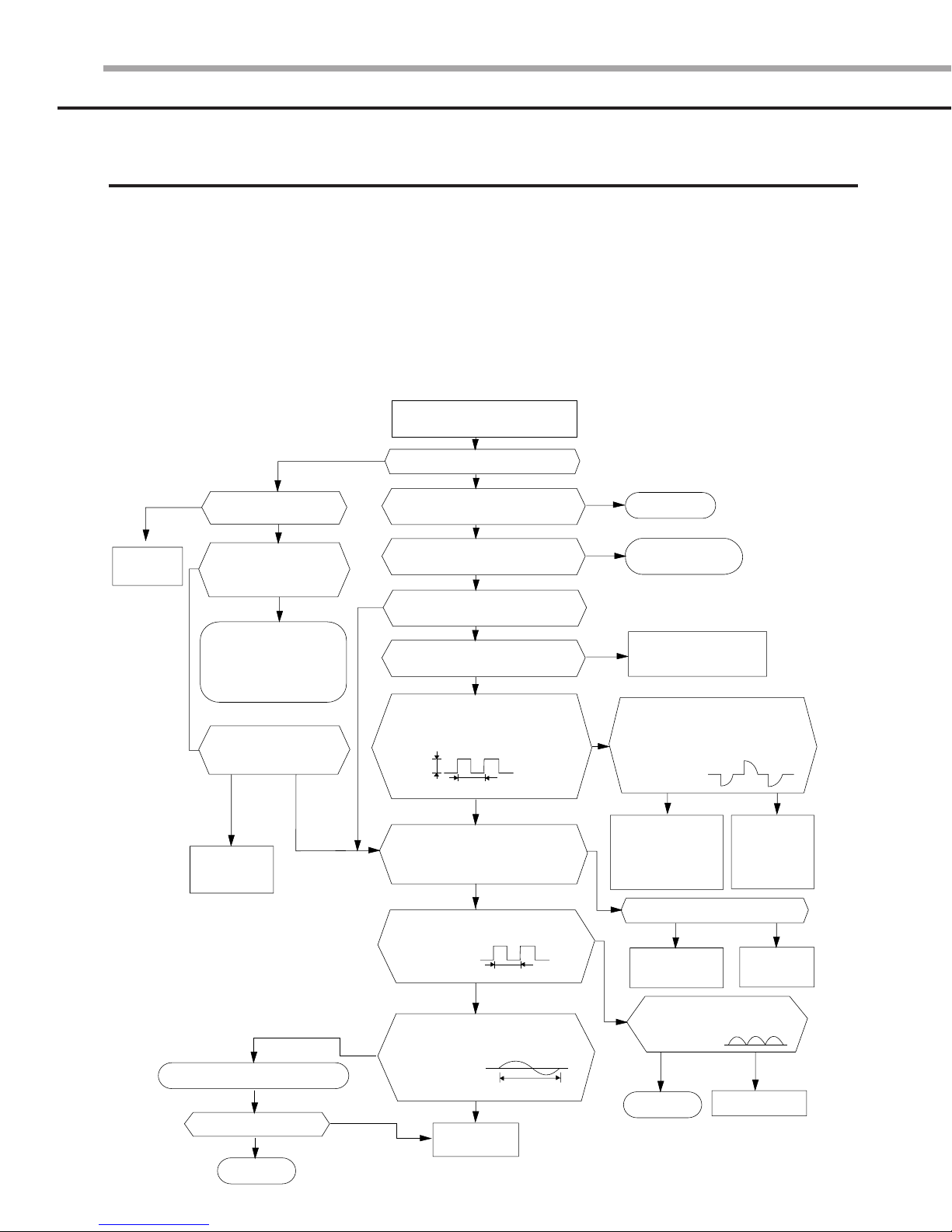
1. No Powerr--
1. No Powe
Initial diagnosis
Initial diagnosis
1) Checklist :
(1) Is input voltage normal?
(2) Is AC power linked correctly?
(3) Is output voltage of DC regulator IC KA78L05 (IC02) normal? (4.5VDC-5.5VDC)
2) Troubleshooting procedure
YES
Replace PCB
display
Is DC voltage of PCB
display normal?
Is voltage rating within ±10%
range applied to the primary
side(~,~) of the “BD71”?
Check linkage between
a power cord and
a terminal tap
Check fuse
Does 325VDC appear in
the secondary side (+, -)
of “BD71”?
Replace
SMPS PARTS
Replace resonator (X301)
Is operation normal?
YES
OK
NO
NO
Remove the power cord and plug in
again in approx. five seconds
NO
NO
YESNO
NO
NO
Does the lamp blink?
Does it start operating when
you push the On/Off button
on the remote control?
Is transmission display of the
remote control unit blinking?
Does the ‘beep’ sound from the
Is DC voltage of the PCB module
Are voltages of #33 (IC04 : compressor),
#36 (IC04 : 4-way valve) and #34 (IC04 :
outdoor fan) of Micom normal? 5VDC
Is voltage of #32 (IC04 : indoor fan) of
DC5V
Is voltage of #10 (IC04) terminal of Micom normal?
Is voltage of #9 (IC04) terminal of Micom normal?
Is voltage of #3 (IC04) terminal of
Are voltages of #12 (IC04) and
#11 (IC04) of Micom normal?
YES
NO
YES
main unit?
YES
normal?
YES
Micom normal?
10ms
NO
YES
Micom normal?
10ms
YES
YES
Replace
Micom
0VDC
5VDC
250ns
YES
NO
NO
YES
NO
NO
Refer to remote control
unit abnormal diagnosis
Are voltages of RY71(Compressor)
normal? DC12V
Is voltage of SS71(indoor fan)?
Check connections
of compressor
and indoor fan
Is output voltage of ICO2 normal?
Check PCB pattern
Replace the main PCB
Normal
Replace PCB
module
YES
Replace
RY71 and
SS71
YES
Replace ICO2
Is voltage output terminal of
PC814A (PC02) normal?
OK
YES
Replace PC814A(PC02)
NO
NO
NO
 Loading...