

Samsung AQ07A1VE, AQ09B1VE, SH12YAB, UQ09B2VE, AQ12A1VE Service Manual
...
SERVICE
Manual
CONTENTSAIR CONDITIONER
1. Precautions
2. Product Specifications
3. Operating Instructions and
Installation
4. Disassembly and Reassembly
5. Troubleshooting
6. Exploded Views and Parts List
7. Block Diagrams
8. PCB Diagrams
9. Wiring Diagrams
10. Schematic Diagrams
ROOM AIR CONDITIONER
INDOOR UNIT OUTDOOR UNIT
AQ07A1VE
AQ07A2VE
AQ07B1VE
AQ07B2VE
AQ09A1VE
AQ09A2VE
AQ09B1VE
AQ09B2VE
AQ12A1VE
AQ12A2VE
AQ12B1VE
AQ12B2VE
SH09ZV
SH12ZV
SH09YAO
SH12YAO
SH07YAB
SH09YAB
SH12YAB
UQ07A1VE
UQ07A2VE
UQ07B1VE
UQ07B2VE
UQ09A1VE
UQ09A2VE
UQ09B1VE
UQ09B2VE
UQ12A1VE
UQ12A2VE
UQ12B1VE
UQ12B2VE
XSH09ZV
XSH12ZV
SH09YAOX
SH12YAOX
SH07YABX
SH09YABX
SH12YABX
1. Precautions
Samsung Electronics 1-1
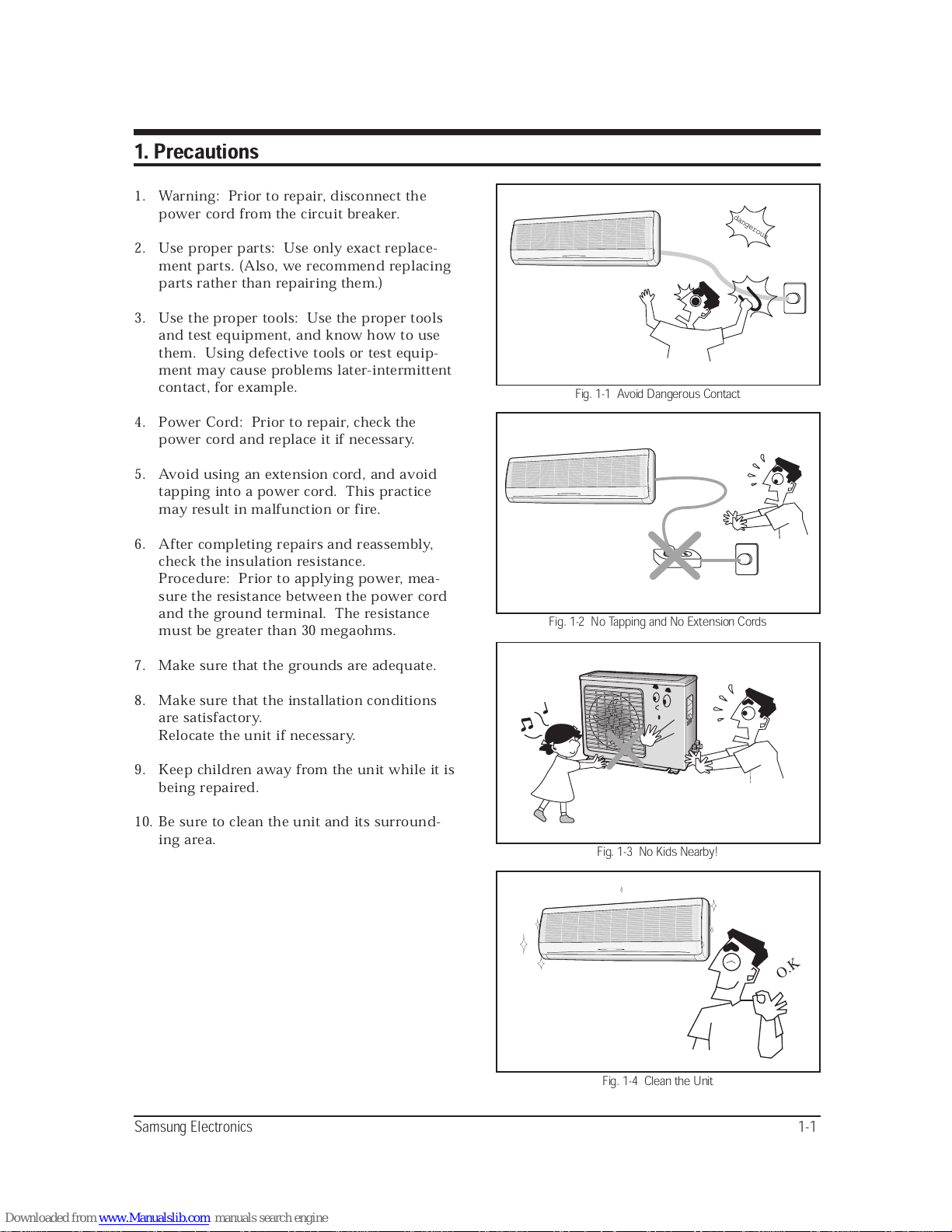
1. Warning: Prior to repair, disconnect the
power cord from the circuit breaker.
2. Use proper parts: Use only exact replace-
ment parts. (Also, we recommend replacing
parts rather than repairing them.)
3. Use the proper tools: Use the proper tools
and test equipment, and know how to use
them. Using defective tools or test equip-
ment may cause problems later-intermittent
contact, for example.
4. Power Cord: Prior to repair, check the
power cord and replace it if necessary.
5. Avoid using an extension cord, and avoid
tapping into a power cord. This practice
may result in malfunction or fire.
6. After completing repairs and reassembly,
check the insulation resistance.
Procedure: Prior to applying power, mea-
sure the resistance between the power cord
and the ground terminal. The resistance
must be greater than 30 megaohms.
7. Make sure that the grounds are adequate.
8. Make sure that the installation conditions
are satisfactory.
Relocate the unit if necessary.
9. Keep children away from the unit while it is
being repaired.
10. Be sure to clean the unit and its surround-
ing area.
dangerous
Fig. 1-1 Avoid Dangerous Contact
Fig. 1-2 No Tapping and No Extension Cords
Fig. 1-3 No Kids Nearby!
O.K
Fig. 1-4 Clean the Unit
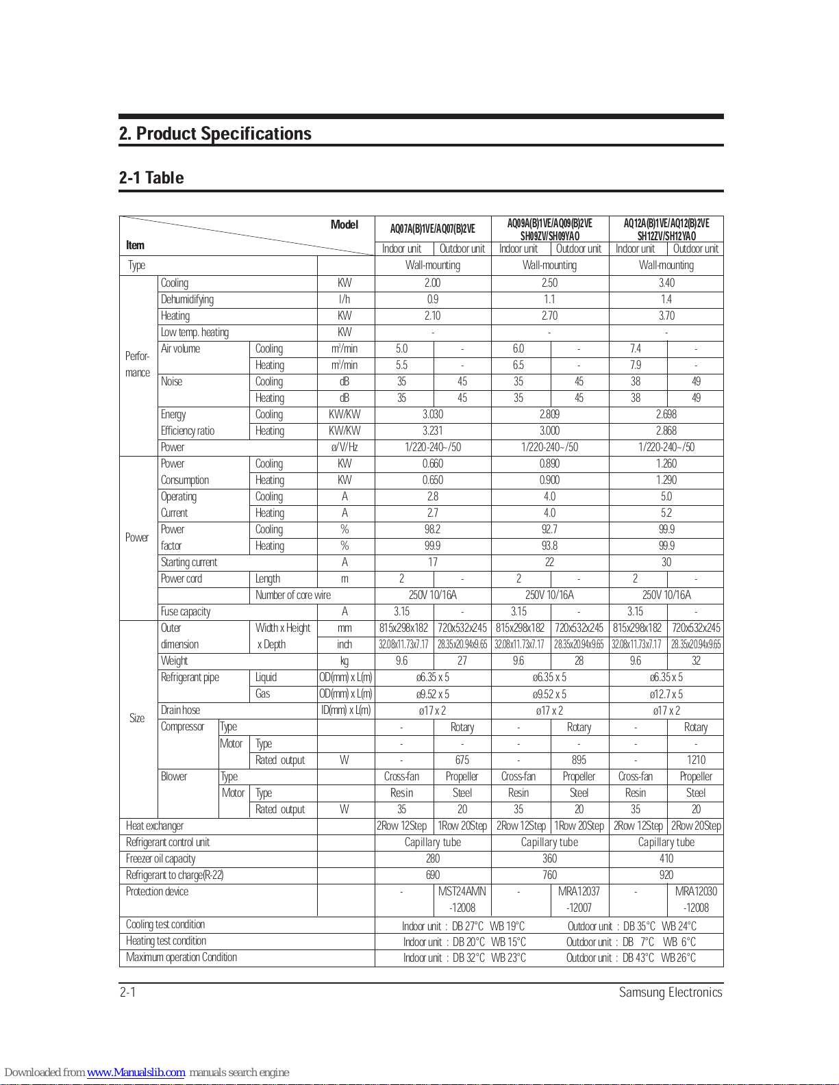
2. Product Specifications
2-1 Table
2-1 Samsung Electronics
Model
Item
Type
Cooling KW
Dehumidifying l/h
Heating KW
Low temp. heating KW
Air volume Cooling m
3
/min
Heating m3/min
Noise Cooling dB
Heating dB
Energy Cooling KW/KW
Efficiency ratio Heating KW/KW
Power ø/V/Hz
Power Cooling KW
Consumption Heating KW
Operating Cooling A
Current Heating A
Power Cooling %
factor Heating %
Starting current A
Power cord Length m
Number of core wire
Fuse capacity A
Outer Width x Height mm
dimension x Depth inch
Weight kg
Refrigerant pipe Liquid OD(mm) x L(m)
Gas OD(mm) x L(m)
Drain hose ID(mm) x L(m)
Compressor Type
Motor Type
Rated output W
Blower Type
Motor Type
Rated output W
Heat exchanger
Refrigerant control unit
Freezer oil capacity
Refrigerant to charge(R-22)
Protection device
Cooling test condition
Heating test condition
Maximum operation Condition
Indoor unit Outdoor unit
Wall-mounting
2.00
0.9
2.10
-
5.0 -
5.5 -
35 45
35 45
3.030
3.231
1/220-240~/50
0.660
0.650
2.8
2.7
98.2
99.9
17
2 -
250V 10/16A
3.15 -
815x298x182 720x532x245
32.08x11.73x7.17 28.35x20.94x9.65
9.6 27
ø6.35 x 5
ø9.52 x 5
ø17 x 2
- Rotary
- -
- 675
Cross-fan Propeller
Resin
Resin Steel
35 20
2Row 12Step 1Row 20Step
Capillary tube
280
690
- MST24AMN
-12008
AQ07A(B)1VE/AQ07(B)2VE
Perfor-
mance
Power
Size
Indoor unit : DB 27°C WB 19°C Outdoor unit : DB 35°C WB 24°C
Indoor unit : DB 20°C WB 15°C Outdoor unit : DB 7°C WB 6°C
Indoor unit : DB 32°C WB 23°C Outdoor unit : DB 43°C WB 26°C
Indoor unit Outdoor unit
Wall-mounting
2.50
1.1
2.70
-
6.0 -
6.5 -
35 45
35 45
2.809
3.000
1/220-240~/50
0.890
0.900
4.0
4.0
92.7
93.8
22
2 -
250V 10/16A
3.15 -
815x298x182 720x532x245
32.08x11.73x7.17 28.35x20.94x9.65
9.6 28
ø6.35 x 5
ø9.52 x 5
ø17 x 2
- Rotary
- -
- 895
Cross-fan Propeller
Resin Steel
35 20
2Row 12Step 1Row 20Step
Capillary tube
360
760
- MRA12037
-12007
Indoor unit Outdoor unit
Wall-mounting
3.40
1.4
3.70
-
7.4 -
7.9 -
38 49
38 49
2.698
2.868
1/220-240~/50
1.260
1.290
5.0
5.2
99.9
99.9
30
2 -
250V 10/16A
3.15 -
815x298x182 720x532x245
32.08x11.73x7.17 28.35x20.94x9.65
9.6 32
ø6.35 x 5
ø12.7 x 5
ø17 x 2
- Rotary
- -
- 1210
Cross-fan Propeller
Resin Steel
35 20
2Row 12Step 2Row 20Step
Capillary tube
410
920
- MRA12030
-12008
AQ09A(B)1VE/AQ09(B)2VE
SH09ZV/SH09YAO
AQ12A(B)1VE/AQ12(B)2VE
SH12ZV/SH12YAO
Samsung Electronics 2-2
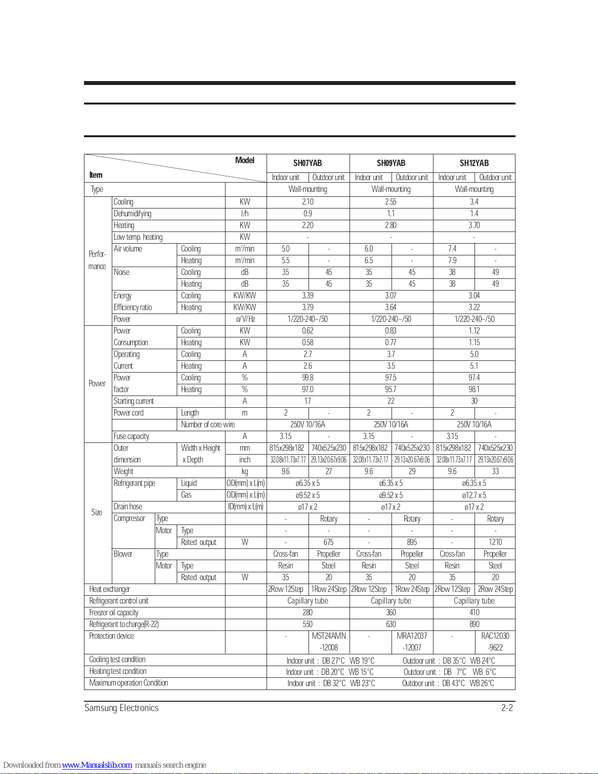
Model
Item
Type
Cooling KW
Dehumidifying l/h
Heating KW
Low temp. heating KW
Air volume Cooling m
3
/min
Heating m3/min
Noise Cooling dB
Heating dB
Energy Cooling KW/KW
Efficiency ratio Heating KW/KW
Power ø/V/Hz
Power Cooling KW
Consumption Heating KW
Operating Cooling A
Current Heating A
Power Cooling %
factor Heating %
Starting current A
Power cord Length m
Number of core wire
Fuse capacity A
Outer Width x Height mm
dimension x Depth inch
Weight kg
Refrigerant pipe Liquid OD(mm) x L(m)
Gas OD(mm) x L(m)
Drain hose ID(mm) x L(m)
Compressor Type
Motor Type
Rated output W
Blower Type
Motor Type
Rated output W
Heat exchanger
Refrigerant control unit
Freezer oil capacity
Refrigerant to charge(R-22)
Protection device
Cooling test condition
Heating test condition
Maximum operation Condition
Indoor unit Outdoor unit
Wall-mounting
2.10
0.9
2.20
-
5.0 -
5.5 -
35 45
35 45
3.39
3.79
1/220-240~/50
0.62
0.58
2.7
2.6
99.8
97.0
17
2 -
250V 10/16A
3.15 -
815x298x182 740x525x230
32.08x11.73x7.17 29.13x20.67x9.06
9.6 27
ø6.35 x 5
ø9.52 x 5
ø17 x 2
- Rotary
- -
- 675
Cross-fan Propeller
Resin Steel
35 20
2Row 12Step 1Row 24Step
Capillary tube
280
550
- MST24AMN
-12008
SH07YAB
Perfor-
mance
Power
Size
Indoor unit : DB 27°C WB 19°C Outdoor unit : DB 35°C WB 24°C
Indoor unit : DB 20°C WB 15°C Outdoor unit : DB 7°C WB 6°C
Indoor unit : DB 32°C WB 23°C Outdoor unit : DB 43°C WB 26°C
Indoor unit Outdoor unit
Wall-mounting
2.55
1.1
2.80
-
6.0 -
6.5 -
35 45
35 45
3.07
3.64
1/220-240~/50
0.83
0.77
3.7
3.5
97.5
95.7
22
2 -
250V 10/16A
3.15 -
815x298x182 740x525x230
32.08x11.73x7.17 29.13x20.67x9.06
9.6 29
ø6.35 x 5
ø9.52 x 5
ø17 x 2
- Rotary
- -
- 895
Cross-fan Propeller
Resin Steel
35 20
2Row 12Step 1Row 24Step
Capillary tube
360
630
- MRA12037
-12007
Indoor unit Outdoor unit
Wall-mounting
3.4
1.4
3.70
-
7.4 -
7.9 -
38 49
38 49
3.04
3.22
1/220-240~/50
1.12
1.15
5.0
5.1
97.4
98.1
30
2 -
250V 10/16A
3.15 -
815x298x182 740x525x230
32.08x11.73x7.17 29.13x20.67x9.06
9.6 33
ø6.35 x 5
ø12.7 x 5
ø17 x 2
- Rotary
- -
- 1210
Cross-fan Propeller
Resin Steel
35 20
2Row 12Step 2Row 24Step
Capillary tube
410
890
- RAC12030
-9622
SH09YAB SH12YAB
2-3 Samsung Electronics
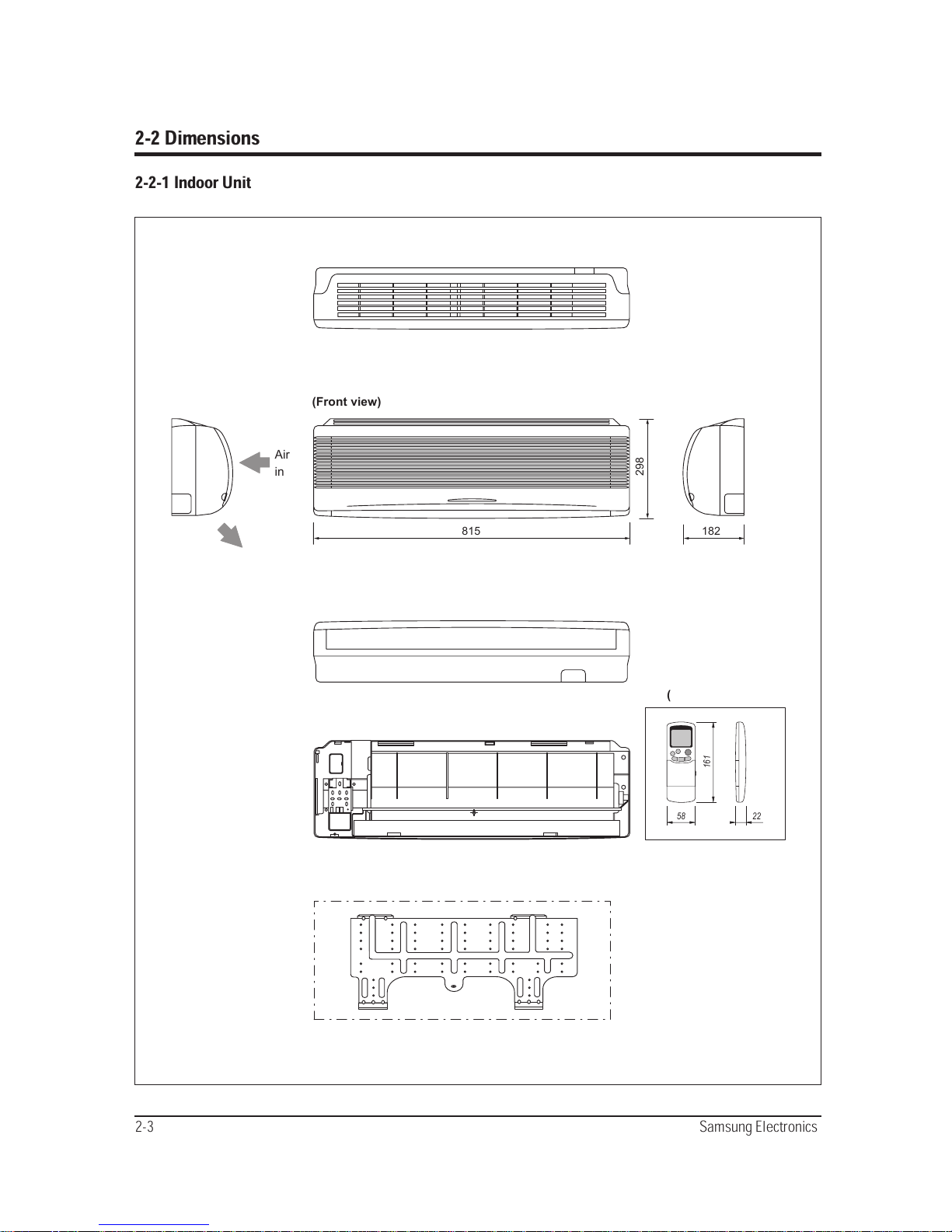
2-2 Dimensions
2-2-1 Indoor Unit
815 182
298
58 22
161
Air
in
(Front view)
(Remote control)
(Rear view)
Air out
Installation plate
Product Specifications
Samsung Electronics 2-4
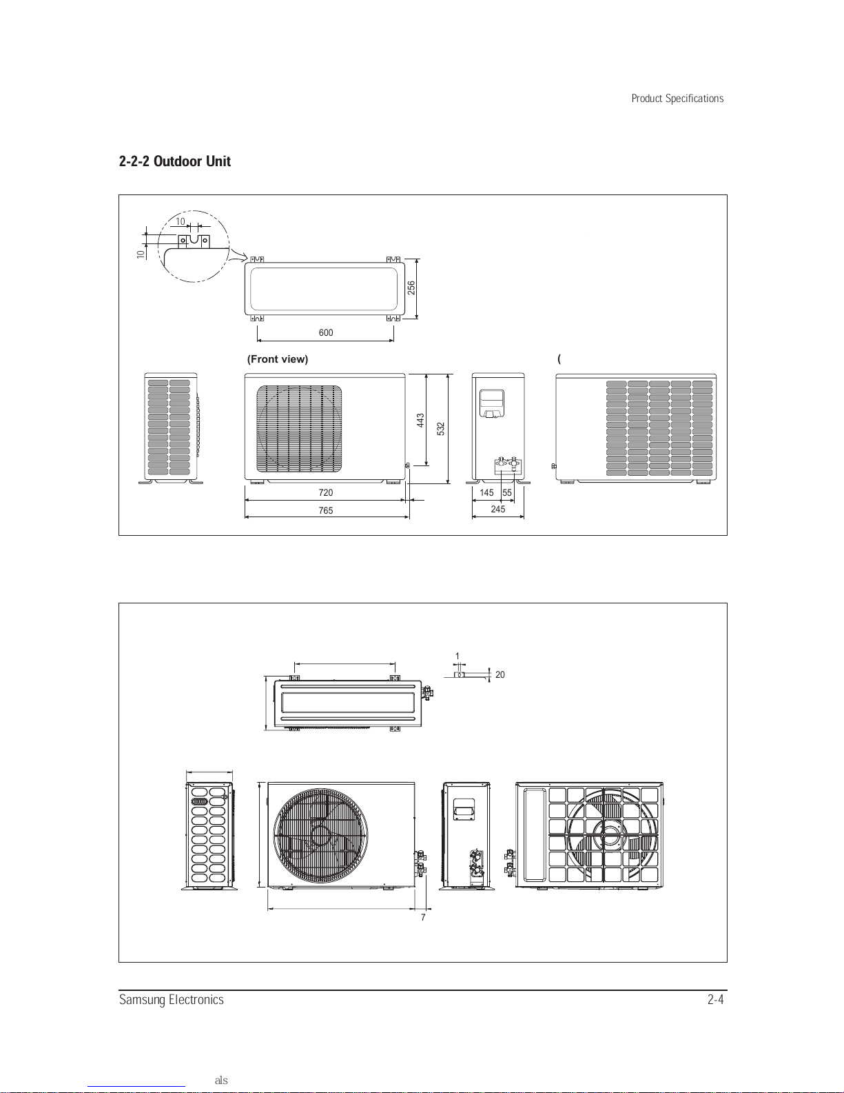
2-2-2 Outdoor Unit
(Front view)
720 145 55
245
600
10
10
765
443
256
532
(Rear view)
230
506
270
525
740
57
20
11
■ ✳✳
YABX
2-5 Samsung Electronics
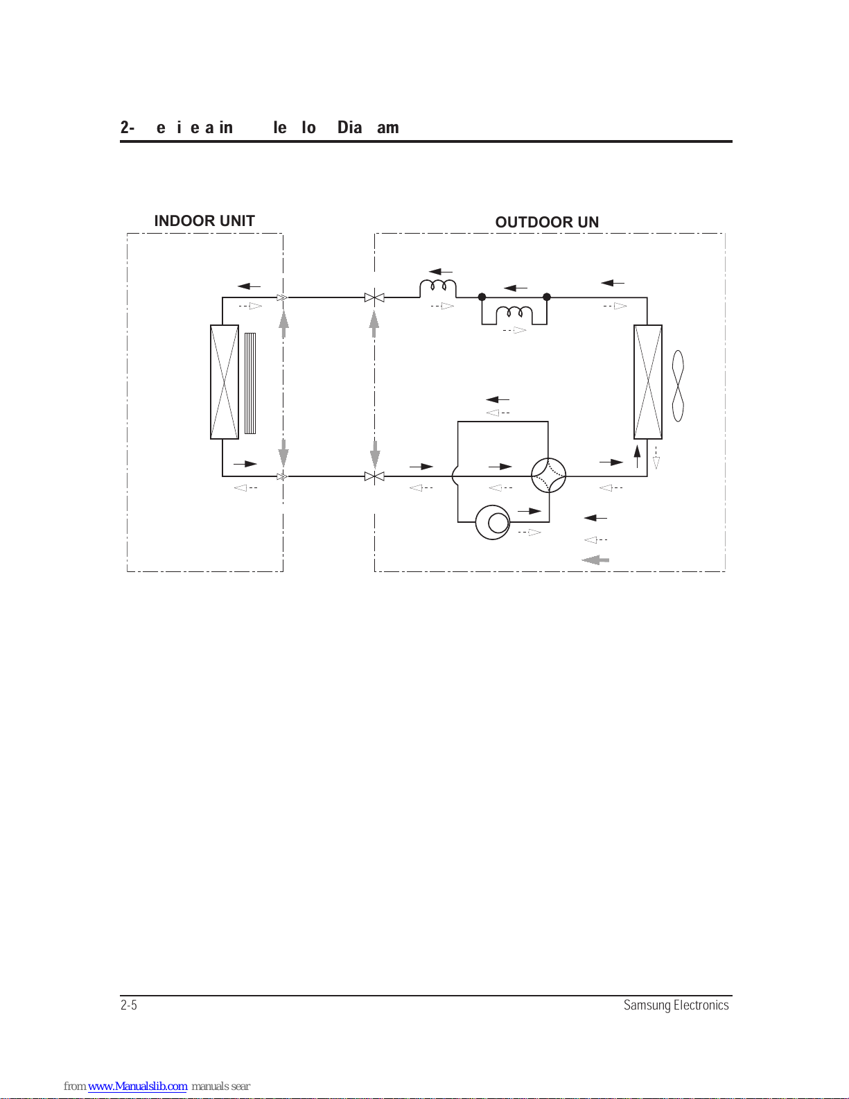
INDOOR UNIT
OUTDOOR UNIT
Heat
exchanger
(Evaporator)
Gas side
3-way valve
2-way valve
Liquid side
Capillary tube
Cooling
Gas leak check point
Cross fan
Heat
exchanger
(Condenser)
Propeller fan
Heating
Capillary tube
Check valve
Compressor
4-way valve
T
1
T
2
2-3 Refrigerating Cycle Block Diagram
Samsung Electronics 3-1
3. Operating Instructions and Installation
3-1 Operating Instructions
NO
1
2
3
4
5
6
7
8
9
10
11
12
13
14
15
NAMED OF KEY
MODE
(UP)
(DOWN)
TURBO
OFF
ON TIMER
OFF TIMER
SET
CANCEL
(UP)
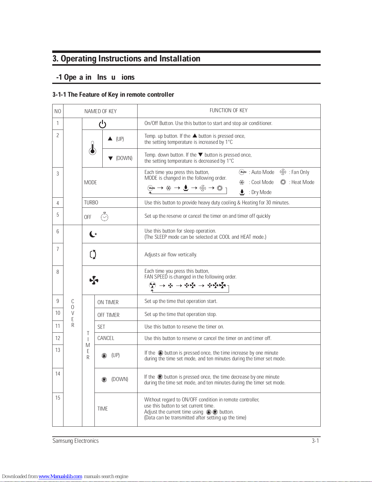
Without regard to ON/OFF condition in remote controller,
use this button to set current time.
Adjust the current time using button.
(Data can be transmitted after setting up the time)
If the button is pressed once, the time decrease by one minute
during the time set mode, and ten minutes during the timer set mode.
If the button is pressed once, the time increase by one minute
during the time set mode, and ten minutes during the timer set mode.
Use this button to reserve or cancel the timer on and timer off.
Use this button to reserve the timer on.
Set up the time that operation stop.
Set up the time that operation start.
Each time you press this button,
FAN SPEED is changed in the following order.
Adjusts air flow vertically.
Use this button for sleep operation.
(The SLEEP mode can be selected at COOL and HEAT mode.)
Set up the reserve or cancel the timer on and timer off quickly
Use this button to provide heavy duty cooling & Heating for 30 minutes.
Each time you press this button,
MODE is changed in the following order.
Temp. down button. If the button is pressed once,
the setting temperature is decreased by 1°C
Temp. up button. If the button is pressed once,
the setting temperature is increased by 1°C
On/Off Button. Use this button to start and stop air conditioner.
FUNCTION OF KEY
(DOWN)
TIME
3-1-1 The Feature of Key in remote controller
C
O
V
E
R
T
I
M
E
R
: Auto Mode : Fan Only
: Cool Mode : Heat Mode
: Dry Mode
3-2 Samsung Electronics
Operating Instructions and Installation
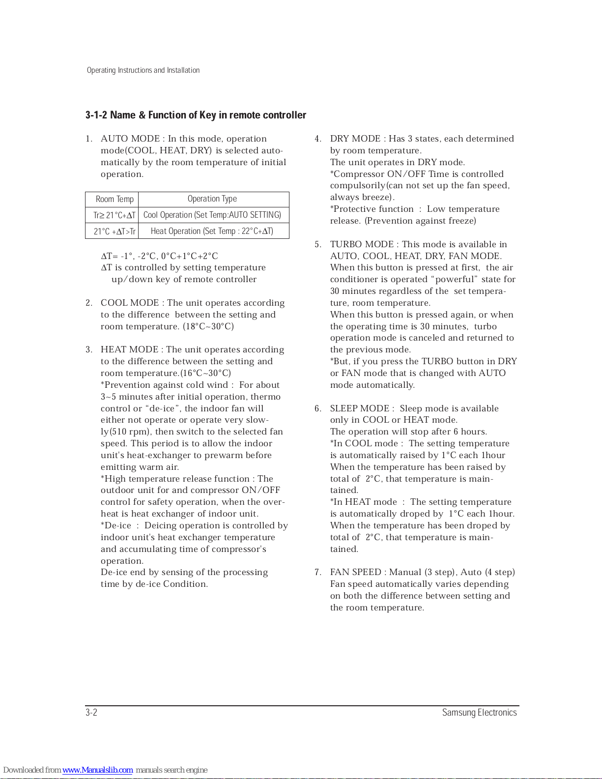
1. AUTO MODE : In this mode, operation
mode(COOL, HEAT, DRY) is selected auto-
matically by the room temperature of initial
operation.
∆
T= -1°, -2°C, 0°C+1°C+2°C
∆
T is controlled by setting temperature
up/down key of remote controller
2. COOL MODE : The unit operates according
to the difference between the setting and
room temperature. (18°C~30°C)
3. HEAT MODE : The unit operates according
to the difference between the setting and
room temperature.(16°C~30°C)
*Prevention against cold wind : For about
3~5 minutes after initial operation, thermo
control or “de-ice”, the indoor fan will
either not operate or operate very slow-
ly(510 rpm), then switch to the selected fan
speed. This period is to allow the indoor
unit's heat-exchanger to prewarm before
emitting warm air.
*High temperature release function : The
outdoor unit for and compressor ON/OFF
control for safety operation, when the over-
heat is heat exchanger of indoor unit.
*De-ice : Deicing operation is controlled by
indoor unit's heat exchanger temperature
and accumulating time of compressor's
operation.
De-ice end by sensing of the processing
time by de-ice Condition.
4. DRY MODE : Has 3 states, each determined
by room temperature.
The unit operates in DRY mode.
*Compressor ON/OFF Time is controlled
compulsorily(can not set up the fan speed,
always breeze).
*Protective function : Low temperature
release. (Prevention against freeze)
5. TURBO MODE : This mode is available in
AUTO, COOL, HEAT, DRY, FAN MODE.
When this button is pressed at first, the air
conditioner is operated “powerful” state for
30 minutes regardless of the set tempera-
ture, room temperature.
When this button is pressed again, or when
the operating time is 30 minutes, turbo
operation mode is canceled and returned to
the previous mode.
*But, if you press the TURBO button in DRY
or FAN mode that is changed with AUTO
mode automatically.
6. SLEEP MODE : Sleep mode is available
only in COOL or HEAT mode.
The operation will stop after 6 hours.
*In COOL mode : The setting temperature
is automatically raised by 1°C each 1hour
When the temperature has been raised by
total of 2°C, that temperature is main-
tained.
*In HEAT mode : The setting temperature
is automatically droped by 1°C each 1hour.
When the temperature has been droped by
total of 2°C, that temperature is main-
tained.
7. FAN SPEED : Manual (3 step), Auto (4 step)
Fan speed automatically varies depending
on both the difference between setting and
the room temperature.
Room Temp
Tr≥21°C+∆T
21°C +∆T>Tr
Operation Type
Cool Operation (Set Temp:AUTO SETTING)
Heat Operation (Set Temp : 22°C+∆T)
3-1-2 Name & Function of Key in remote controller
Samsung Electronics 3-3
Operating Instructions and Installation
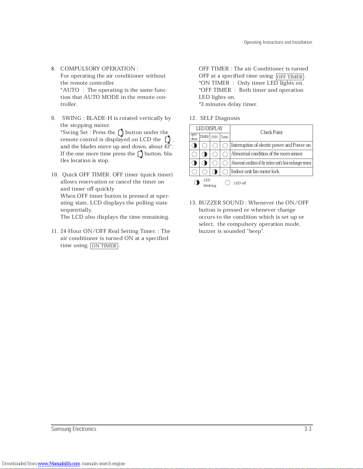
8. COMPULSORY OPERATION :
For operating the air conditioner without
the remote controller.
*AUTO : The operating is the same func-
tion that AUTO MODE in the remote con-
troller.
9. SWING : BLADE-H is rotated vertically by
the stepping motor.
*Swing Set : Press the button under the
remote control is displayed on LCD the ,
and the blades move up and down, about 43°.
If the one more time press the button, bla-
tles location is stop.
10. Quick OFF TIMER: OFF timer (quick timer)
allows reservation or cancel the timer on
and timer off quickly
When OFF timer button is pressed at oper-
ating state, LCD displays the polling state
sequentially.
The LCD also displays the time remaining.
11. 24-Hour ON/OFF Real Setting Timer. : The
air conditioner is turned ON at a specified
time using .
OFF TIMER : The air Conditioner is turned
OFF at a specified time using .
*ON TIMER : Only timer LED lights on.
*OFF TIMER : Both timer and operation
LED lights on.
*3 minutes delay timer.
12. SELF Diagnosis
13. BUZZER SOUND : Whenever the ON/OFF
button is pressed or whenever change
occurs to the condition which is set up or
select, the compulsory operation mode,
buzzer is sounded "beep".
ON TIMER
OFF TIMER
Interruption of electric power and Power on.
Check Point
LED DISPLAY
oper-
ation
TIMER
FAN
LED
:
blinking
: LED off
Turbo
Abnormal condition of the room sensor.
Indoor unit fan motor lock.
Abnormal condition of the indoor unit's heat exchanger sensor.
3-4 Samsung Electronics
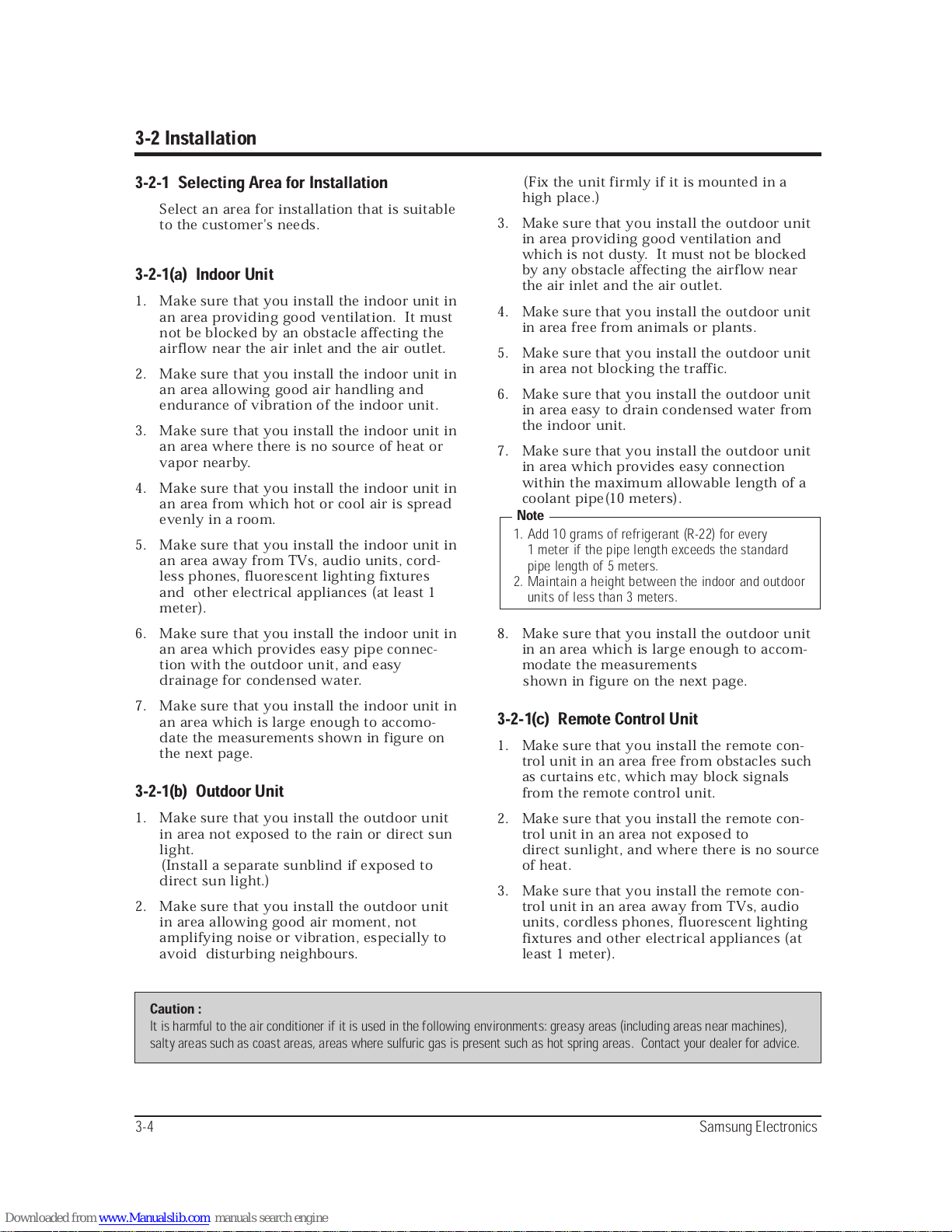
3-2 Installation
3-2-1 Selecting Area for Installation
Select an area for installation that is suitable
to the customer's needs.
3-2-1(a) Indoor Unit
1. Make sure that you install the indoor unit in
an area providing good ventilation. It must
not be blocked by an obstacle affecting the
airflow near the air inlet and the air outlet.
2. Make sure that you install the indoor unit in
an area allowing good air handling and
endurance of vibration of the indoor unit.
3. Make sure that you install the indoor unit in
an area where there is no source of heat or
vapor nearby.
4. Make sure that you install the indoor unit in
an area from which hot or cool air is spread
evenly in a room.
5. Make sure that you install the indoor unit in
an area away from TVs, audio units, cord-
less phones, fluorescent lighting fixtures
and other electrical appliances (at least 1
meter).
6. Make sure that you install the indoor unit in
an area which provides easy pipe connec-
tion with the outdoor unit, and easy
drainage for condensed water.
7. Make sure that you install the indoor unit in
an area which is large enough to accomo-
date the measurements shown in figure on
the next page.
3-2-1(b) Outdoor Unit
1. Make sure that you install the outdoor unit
in area not exposed to the rain or direct sun
light.
(Install a separate sunblind if exposed to
direct sun light.)
2. Make sure that you install the outdoor unit
in area allowing good air moment, not
amplifying noise or vibration, especially to
avoid disturbing neighbours.
(Fix the unit firmly if it is mounted in a
high place.)
3. Make sure that you install the outdoor unit
in area providing good ventilation and
which is not dusty. It must not be blocked
by any obstacle affecting the airflow near
the air inlet and the air outlet.
4. Make sure that you install the outdoor unit
in area free from animals or plants.
5. Make sure that you install the outdoor unit
in area not blocking the traffic.
6. Make sure that you install the outdoor unit
in area easy to drain condensed water from
the indoor unit.
7. Make sure that you install the outdoor unit
in area which provides easy connection
within the maximum allowable length of a
coolant pipe(10 meters).
8. Make sure that you install the outdoor unit
in an area which is large enough to accom-
modate the measurements
shown in figure on the next page.
3-2-1(c) Remote Control Unit
1. Make sure that you install the remote con-
trol unit in an area free from obstacles such
as curtains etc, which may block signals
from the remote control unit.
2. Make sure that you install the remote con-
trol unit in an area not exposed to
direct sunlight, and where there is no source
of heat.
3. Make sure that you install the remote con-
trol unit in an area away from TVs, audio
units, cordless phones, fluorescent lighting
fixtures and other electrical appliances (at
least 1 meter).
Caution :
It is harmful to the air conditioner if it is used in the following environments: greasy areas (including areas near machines),
salty areas such as coast areas, areas where sulfuric gas is present such as hot spring areas. Contact your dealer for advice.
1. Add 10 grams of refrigerant (R-22) for every
1 meter if the pipe length exceeds the standard
pipe length of 5 meters.
2. Maintain a height between the indoor and outdoor
units of less than 3 meters.
Note
3-5Samsung Electronics
Operating Instructions and Installation
A
B
Cut the piping hole
sloped slightly
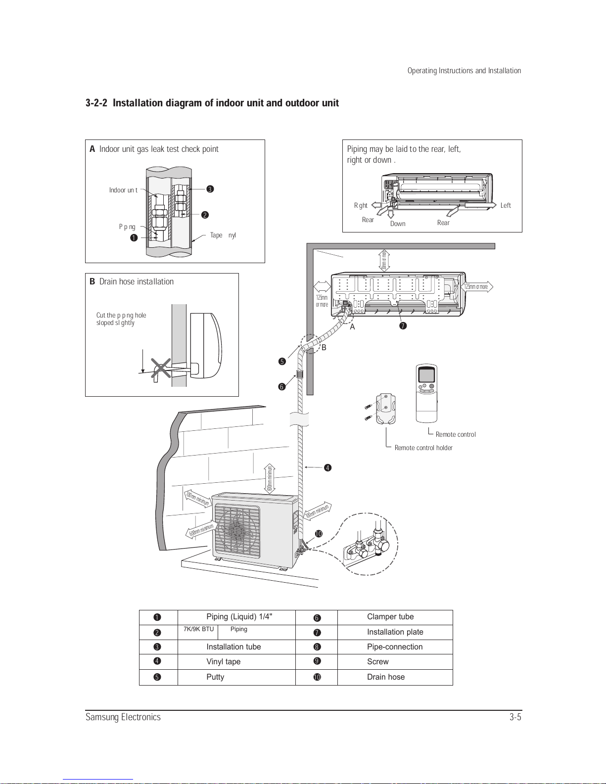
3-2-2 Installation diagram of indoor unit and outdoor unit
A
Indoor unit gas leak test check point
Tape vinyl
Piping
Indoor unit
B
Drain hose installation
Cut the piping hole
sloped slightly
Piping (Liquid) 1/4" Clamper tube
Installation plate
Installation tube Pipe-connection
Vinyl tape Screw
Putty Drain hose
Piping may be laid to the rear, left,
right or down .
Right
Rear
Down
30mm or more
600mm minimum
600mm minimum
100mm minimum
100mm minimum
125mm
or more
125mm or more
Rear
Left
3
2
5
7
6
4
10
1
2
3
4
5
6
7
8
9
10
1
Remote control
Remote control holder
7K/9K BTU Piping(Gas)3/8”
12K BTU Piping(Gas)1/2”
3-6 Samsung Electronics
Operating Instructions and Installation
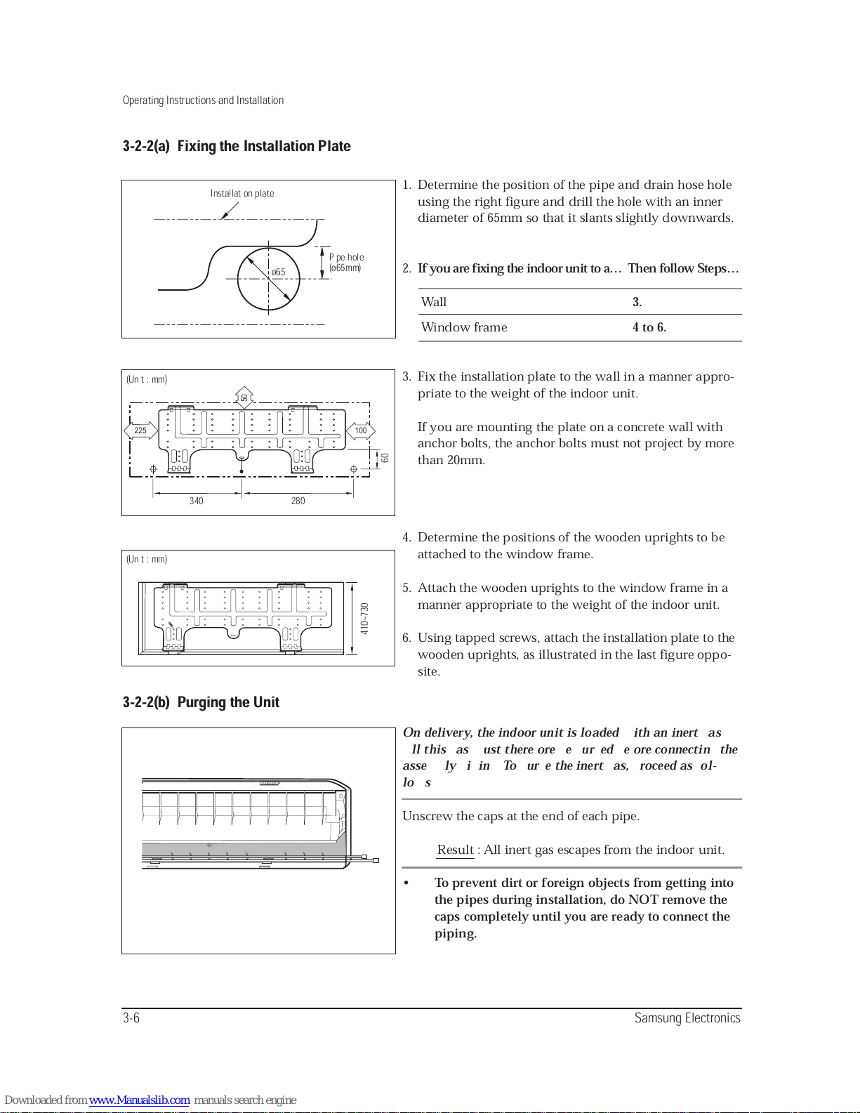
3-2-2(a) Fixing the Installation Plate
3-2-2(b) Purging the Unit
Installation plate
Pipe hole
(ø65mm)
ø65
50
225
100
340
(Unit : mm)
280
60
(Unit : mm)
410~730
1. Determine the position of the pipe and drain hose hole
using the right figure and drill the hole with an inner
diameter of 65mm so that it slants slightly downwards.
2.
If you are fixing the indoor unit to a… Then follow Steps…
Wall
3.
Window frame
4 to 6.
3. Fix the installation plate to the wall in a manner appro-
priate to the weight of the indoor unit.
If you are mounting the plate on a concrete wall with
anchor bolts, the anchor bolts must not project by more
than 20mm.
4. Determine the positions of the wooden uprights to be
attached to the window frame.
5. Attach the wooden uprights to the window frame in a
manner appropriate to the weight of the indoor unit.
6. Using tapped screws, attach the installation plate to the
wooden uprights, as illustrated in the last figure oppo-
site.
On delivery, the indoor unit is loaded with an inert gas.
All this gas must therefore be purged before connecting the
assembly piping. To purge the inert gas, proceed as fol-
lows.
Unscrew the caps at the end of each pipe.
Result : All inert gas escapes from the indoor unit.
• To prevent dirt or foreign objects from getting into
the pipes during installation, do NOT remove the
caps completely until you are ready to connect the
piping.
3-7
Samsung Electronics
Operating Instructions and Installation
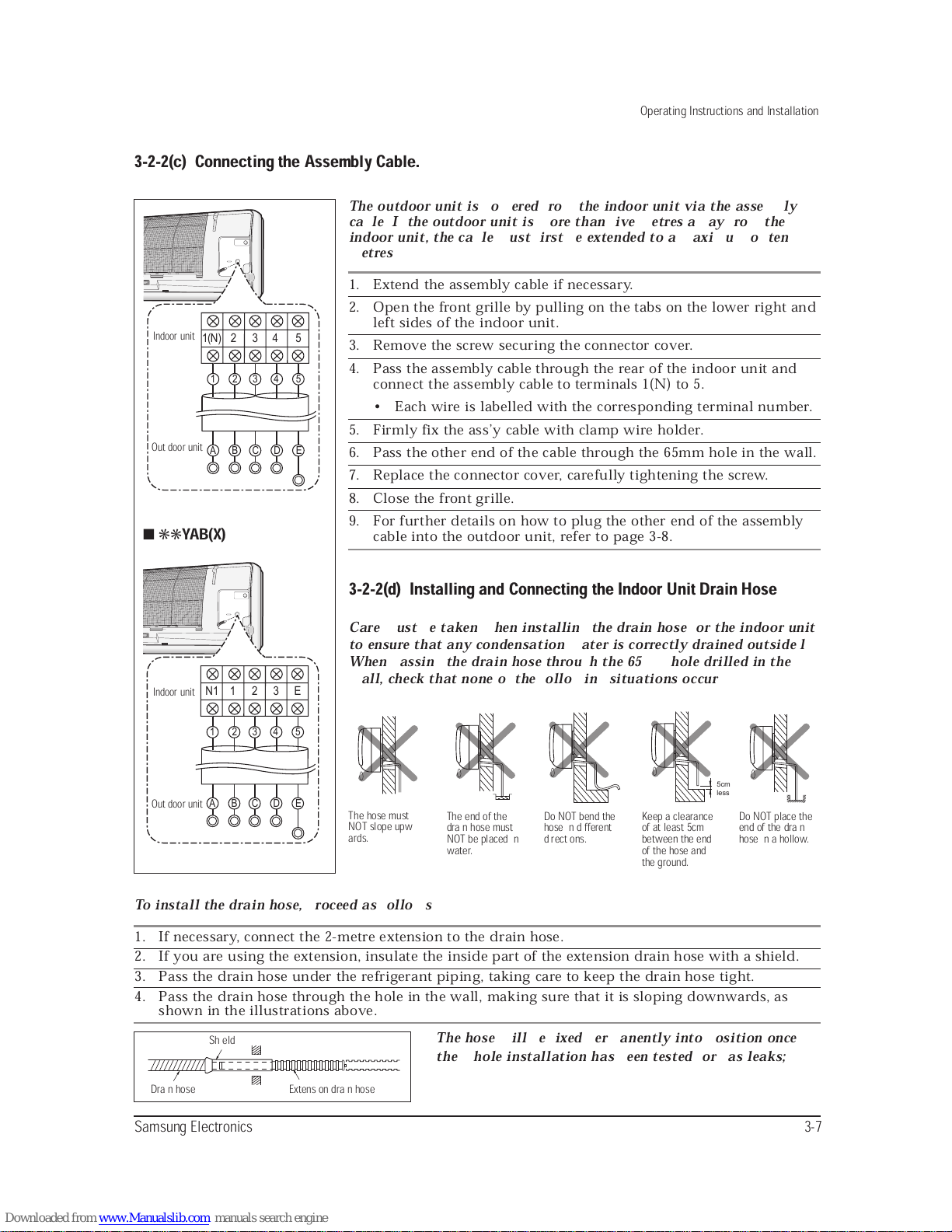
To install the drain hose, proceed as follows.
1. If necessary, connect the 2-metre extension to the drain hose.
2. If you are using the extension, insulate the inside part of the extension drain hose with a shield.
3. Pass the drain hose under the refrigerant piping, taking care to keep the drain hose tight.
4. Pass the drain hose through the hole in the wall, making sure that it is sloping downwards, as
shown in the illustrations above.
3-2-2(d) Installing and Connecting the Indoor Unit Drain Hose
Care must be taken when installing the drain hose for the indoor unit
to ensure that any condensation water is correctly drained outside.l
When passing the drain hose through the 65mm hole drilled in the
wall, check that none of the following situations occur.
3-2-2(c) Connecting the Assembly Cable.
1(N) 2 3 4 5
1 5432
A B C D E
The outdoor unit is powered from the indoor unit via the assembly
cable. If the outdoor unit is more than five metres away from the
indoor unit, the cable must first be extended to a maximum of ten
metres.
1. Extend the assembly cable if necessary.
2. Open the front grille by pulling on the tabs on the lower right and
left sides of the indoor unit.
3. Remove the screw securing the connector cover.
4. Pass the assembly cable through the rear of the indoor unit and
connect the assembly cable to terminals 1(N) to 5.
• Each wire is labelled with the corresponding terminal number.
5. Firmly fix the ass’y cable with clamp wire holder.
6. Pass the other end of the cable through the 65mm hole in the wall.
7. Replace the connector cover, carefully tightening the screw.
8. Close the front grille.
9. For further details on how to plug the other end of the assembly
cable into the outdoor unit, refer to page 3-8.
The hose will be fixed permanently into position once
the whole installation has been tested for gas leaks;
Keep a clearance
of at least 5cm
between the end
of the hose and
the ground.
Do NOT bend the
hose in different
directions.
The end of the
drain hose must
NOT be placed in
water.
The hose must
NOT slope upw
ards.
Do NOT place the
end of the drain
hose in a hollow.
Shield
Drain hose Extension drain hose
Indoor unit
Out door unit
5cm
less
N1 1 2 3 E
1 5432
A B C D E
■ ✳✳
YAB(X)
Indoor unit
Out door unit
3-8 Samsung Electronics
Operating Instructions and Installation
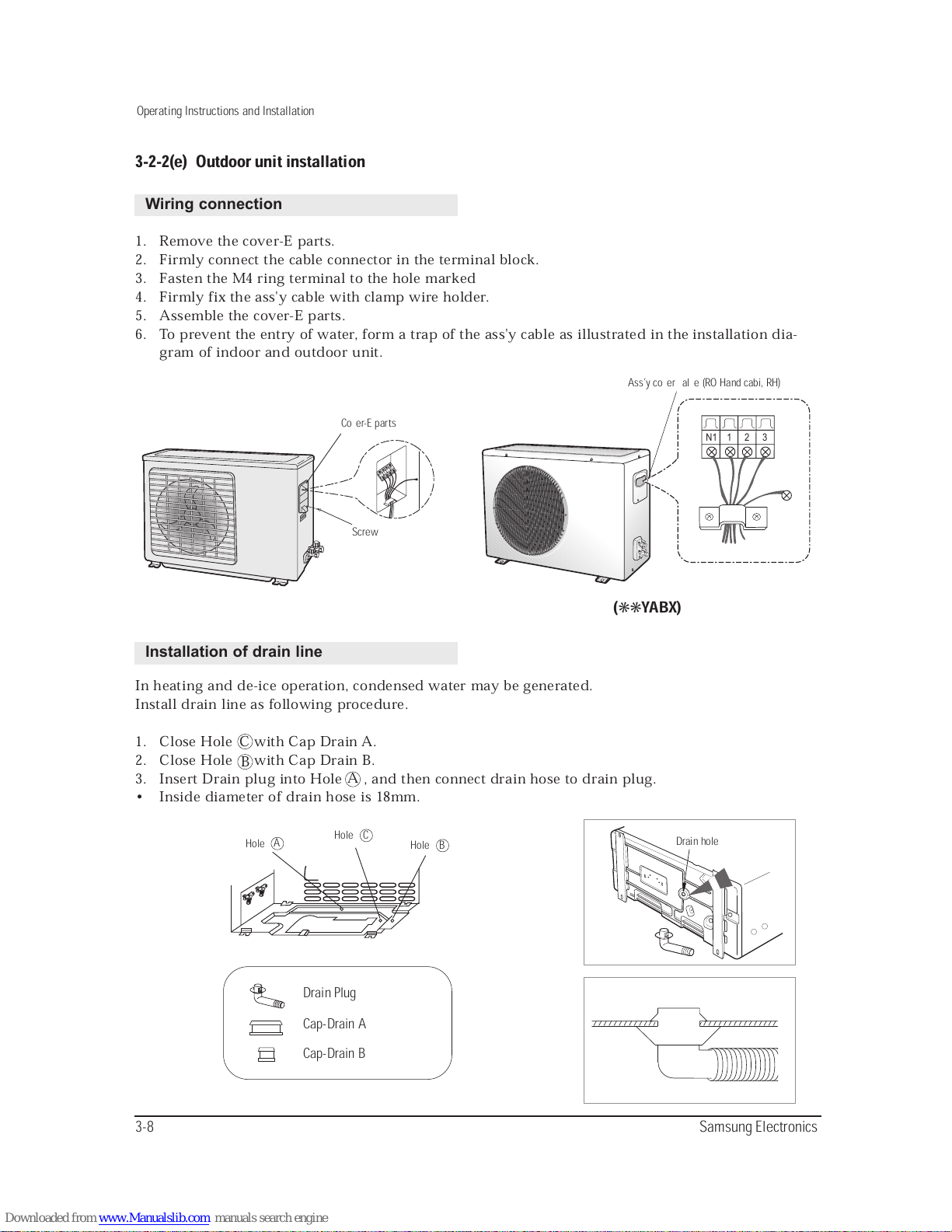
3-2-2(e) Outdoor unit installation
1. Remove the cover-E parts.
2. Firmly connect the cable connector in the terminal block.
3. Fasten the M4 ring terminal to the hole marked
4. Firmly fix the ass'y cable with clamp wire holder.
5. Assemble the cover-E parts.
6. To prevent the entry of water, form a trap of the ass'y cable as illustrated in the installation dia-
gram of indoor and outdoor unit.
In heating and de-ice operation, condensed water may be generated.
Install drain line as following procedure.
1. Close Hole with Cap Drain A.
2. Close Hole with Cap Drain B.
3. Insert Drain plug into Hole , and then connect drain hose to drain plug.
• Inside diameter of drain hose is 18mm.
Wiring connection
Installation of drain line
A B C D
N1 1 2 3
Cover-E parts
Screw
Hole
C
B
A
A
Hole
C
Hole
B
Drain Plug
Cap-Drain A
Cap-Drain B
Ass’y cover valve (RO Hand cabi, RH)
Drain hole
(✳✳YABX)
Samsung Electronics 3-9
Operating Instructions and Installation
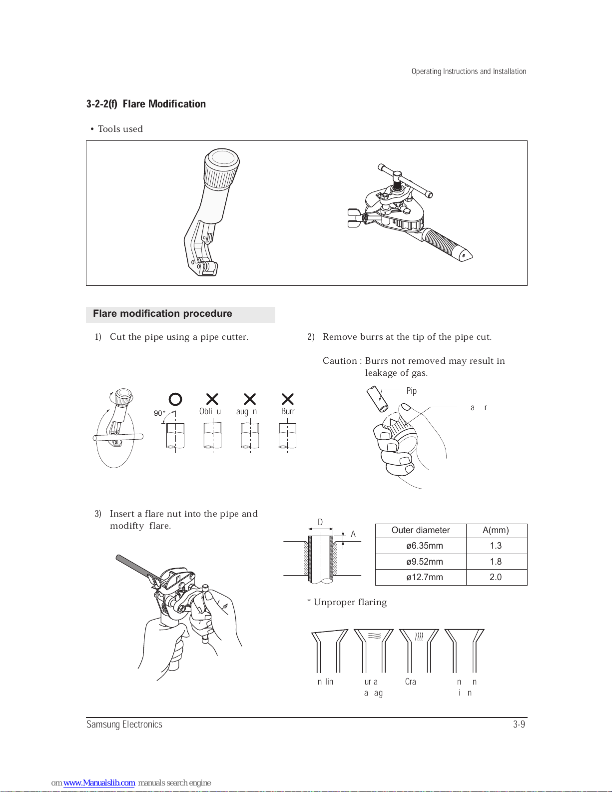
3-2-2(f) Flare Modification
Flare modification procedure
1) Cut the pipe using a pipe cutter.
• Tools used
2) Remove burrs at the tip of the pipe cut.
Caution : Burrs not removed may result in
leakage of gas.
3) Insert a flare nut into the pipe and
modifty flare.
* Unproper flaring
Outer diameter A(mm)
ø6.35mm 1.3
ø9.52mm 1.8
ø12.7mm 2.0
90
D
A
Oblique Raughness Burr
Pipe
Reamer
Inclined Surface
damaged
Cracked Uneven
thickness
D
A
3-10 Samsung Electronics
Operating Instructions and Installation
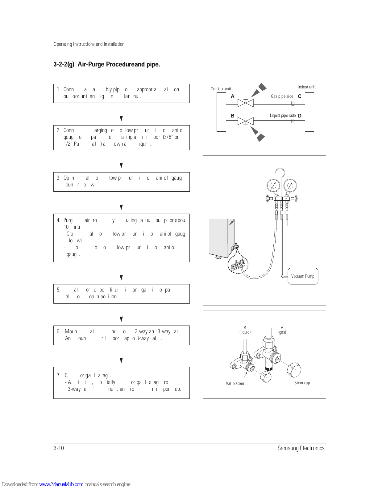
3-2-2(g) Air-Purge Procedureand pipe.
A
B
C
D
Outdoor unit
Indoor unit
Gas pipe side
Liquid pipe side
Vacuum Pump
B
(liquid)
Valve stem
Stem cap
A
(gas)
3 Open the valve of the low pressure side of manifold gauge
counter-clockwise.
6. Mount the valve stem nuts to the 2-way and 3-way valve.
And mount the service port cap to 3-way valve.
4. Purge the air from the system using vacuum pump for about
10 minutes.
- Close the valve of the low pressure side of manifold gauge
clockwise.
- Remove the hose of the low pressure side of manifold
gauge.
7. Check for gas leakage.
- At this time, especially check for gas leakage from the
3-way valve’s stem nuts, and from the service port cap.
5. Set valve cork of both liquid side and gas side of packed
valve to the open position.
1. Connect each assembly pipe to the appropriate valve on the
outdoor unit and tighten the flare nut.
2 Connect the charging hose of low pressure side of manifold
gauge to the packed valve having a service port (3/8” or
1/2” Packed valve) as shown at the figure.
Samsung Electronics 3-11
Operating Instructions and Installation
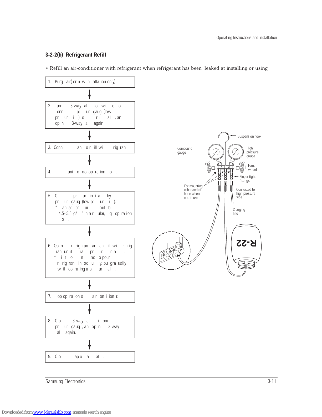
3-2-2(h) Refrigerant Refill
• Refill an air-conditioner with refrigerant when refrigerant has been leaked at installing or using
1. Purge air(for new installation only).
3. Connect the tank to refill with Refrigerant
4. Set the unit to cool operation mode.
7. Stop operation of the air conditioner.
9. Close the cap of each valve.
2. Turn the 3-way valve clockwise to close,
connect the pressure gauge(low
pressure side) to the service valve, and
open the 3-way valve again.
5. Check the pressure indicated by the
pressure gauge(low pressure side).
* Standard pressure is should be
4.5~5.5kg/cm
2
in a reqular, high operation
mode.
6. Open the refrigerant tank and fill with refrig-
erant until the rated pressure is reached.
* It is recommended not to pour the
refrigerant in too quickly, but gradually
while operating a pressure valve.
8. Close the 3-way valve, disconnect the
pressure gauge, and open the 3-way
valve again.
R-22
Suspension hook
High
pressure
gauge
Hand
wheel
Finger tight
fittings
Connected to
high pressure
side
Charging
line
For mounting
other and of
hose when
not in use
Compound
gauge
3-12 Samsung Electronics
Operating Instructions and Installation
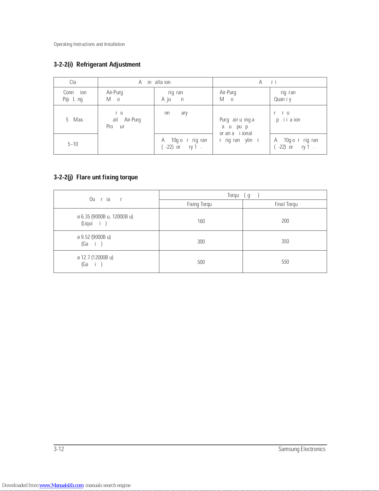
3-2-2(i) Refrigerant Adjustment
3-2-2(j) Flare unt fixing torque
Class At installation At service
Outter diameter
ø 6.35 (9000Btu, 12000Btu)
(Liquid Side)
ø 9.52 (9000Btu)
(Gas Side)
ø 12.7 (12000Btu)
(Gas Side)
160
300
500
200
350
550
Fixing Torque Final Torque
Torque (kg.cm)
Connection
Pipe Length
5m Max.
5~10m
Air-Purge
Method
Refer to the
detailed Air-Purge
Procedure
Refrigerant
Adjustment
Unnecessary
Add 10g of refrigerant
(R-22) for every 1m.
Air-Purge
Method
Purge air using a
vaccum pump
or an additional
refrigerant cylinder.
Refrigerant
Quantity
refer to
specification sheet
Add 10g of refrigerant
(R-22) for every 1m.
Samsung Electronics 3-13
Operating Instructions and Installation
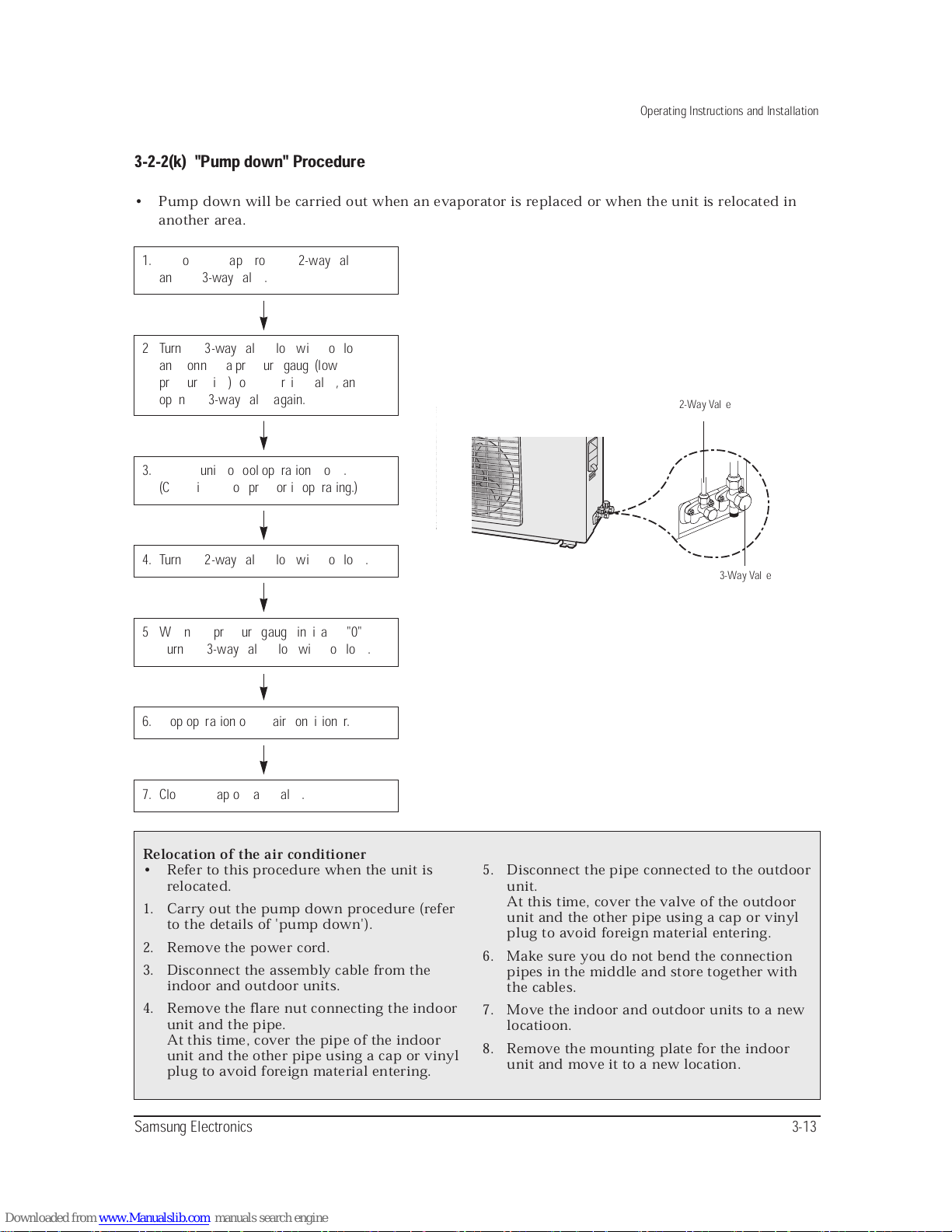
3-2-2(k) "Pump down" Procedure
• Pump down will be carried out when an evaporator is replaced or when the unit is relocated in
another area.
1. Remove the caps from the 2-way valve
and the 3-way valve.
3. Set the unit to cool operation mode.
(Check if the compressor is operating.)
5 When the pressure gauge indicates "0"
turn the 3-way valve clockwise to close.
4. Turn the 2-way valve clockwise to close.
6. Stop operation of the air conditioner.
7. Close the cap of each valve.
2 Turn the 3-way valve clockwise to close
and connect a pressure gauge(low
pressure side) to the service valve, and
open the 3-way valve again.
Relocation of the air conditioner
• Refer to this procedure when the unit is
relocated.
1. Carry out the pump down procedure (refer
to the details of 'pump down').
2. Remove the power cord.
3. Disconnect the assembly cable from the
indoor and outdoor units.
4. Remove the flare nut connecting the indoor
unit and the pipe.
At this time, cover the pipe of the indoor
unit and the other pipe using a cap or vinyl
plug to avoid foreign material entering.
5. Disconnect the pipe connected to the outdoor
unit.
At this time, cover the valve of the outdoor
unit and the other pipe using a cap or vinyl
plug to avoid foreign material entering.
6. Make sure you do not bend the connection
pipes in the middle and store together with
the cables.
7. Move the indoor and outdoor units to a new
locatioon.
8. Remove the mounting plate for the indoor
unit and move it to a new location.
2-Way Valve
3-Way Valve
 Loading...