

Samsung UN40H4203AHXPA, UN48H4203AHXPA Schematic
LED TV
Chassis : U8MC
Model : UN40H4203AH
UN48H4203AH
SERVICE
LED TV Contents
1. Precautions
2. Product specications
3. Disassembly and Reassembly
4. Troubleshooting
5. Wiring Diagram
Manual
UN**H4203AH

Contents
1. Precautions ...................................................................................................................1-1
1-1. Safety Precautions ..............................................................................................................1-1
1-1-1. Warnings ...................................................................................................................1-1
1-1-2. Servicing the LED TV ...............................................................................................1-1
1-1-3. Fire and Shock Hazard .............................................................................................1-1
1-1-4. Product Safety Notices ............................................................................................. 1-2
1-2. Servicing Precautions ..........................................................................................................1-3
1-2-1. General Servicing Precautions ................................................................................. 1-3
1-3. Static Electricity Precautions ...............................................................................................1-4
1-4. Installation Precautions .......................................................................................................1-5
2. Product Specications.................................................................................................2-1
2-1. Product information .............................................................................................................2-1
2-2. Product specication ...........................................................................................................2-2
2-2-1. Detailed Specications .............................................................................................2-2
2-2-2. Specications ...........................................................................................................2-7
2-3. Accessories ........................................................................................................................2-8
3. Disassembly and Reassembly ....................................................................................3-1
3-1. Disassembly and Reassembly ............................................................................................3-1
3-2. Disassembly(PTC) ...............................................................................................................3-4
4. Troubleshooting ...........................................................................................................4-1
4-1. Troubleshooting ...................................................................................................................4-1
4-1-1. Testing the Picture ....................................................................................................4-1
4-1-2. Testing the Sound .....................................................................................................4-3
4-1-3. There is a problem with the broadcast ......................................................................4-4
4-1-4. My computer won’t connect ......................................................................................4-4
4-1-5. I can’t connect to the Internet ...................................................................................4-5
4-1-6. My le won’t play ......................................................................................................4-5
4-1-7. I am having trouble launching/using apps ................................................................4-5
4-1-8. I want to reset the TV ................................................................................................4-5
4-1-9. Other Issues .............................................................................................................4-6
4-2. Connect ...............................................................................................................................4-7
4-3. Factory Mode Adjustments ..................................................................................................4-8
4-3-1. Detail Factory Option ................................................................................................4-8
4-3-2. Entering Factory Mode .............................................................................................4-9
4-3-3. Factory Data ...........................................................................................................4-10

4-4. White Balance ...................................................................................................................4-23
4-4-1. Calibration ..............................................................................................................4-23
4-4-2. Service Adjustment ................................................................................................. 4-23
4-4-3. Adjustment .............................................................................................................. 4-25
4-5. Software Upgrade ..............................................................................................................4-26
4-5-1. By USB ...................................................................................................................4-26
4-5-2. By Online ................................................................................................................4-26
4-5-3. Alternative Software (Backup) ................................................................................ 4-26
4-6. Cover Rear Dimension ......................................................................................................4-27
5. Wiring Diagram .............................................................................................................5-1
5-1. Wiring Diagram ....................................................................................................................5-1
5-2. Connector ............................................................................................................................5-2
5-3. Connector Functions ...........................................................................................................5-4
5-4. Cables .................................................................................................................................5-5
5-5. The Types of Module ...........................................................................................................5-6

This Service Manual is a property of Samsung Electronics Co.,Ltd.
Any unauthorized use of Manual can be punished under applicable
International and/or domestic law.
© 2014 Samsung Electronics Co.,Ltd.
All rights reserved.
Printed in Korea
1. Precautions
1. Precautions
1-1. Safety Precautions
Follow these safety, servicing and ESD precautions to prevent damage and to protect against potential hazards such as
electrical shock.
1-1-1. Warnings
For continued safety, do not attempt to modify the circuit board.
WARNING
1-1-2. Servicing the LED TV
When servicing the LED TV, Disconnect the AC line cord from the AC outlet.1.
It is essential that service technicians have an accurate voltage meter available at all times. Check the calibration of this 2.
meter periodically.
1-1-3. Fire and Shock Hazard
Before returning the monitor to the user, perform the following safety checks:
Inspect each lead dress to make certain that the leads are not pinched or that hardware is not lodged between the 1.
chassis and other metal parts in the monitor.
Inspect all protective devices such as nonmetallic control knobs, insulating materials, cabinet backs, adjustment and 2.
compartment covers or shields, isolation resistorcapacitor networks, mechanical insulators, etc.
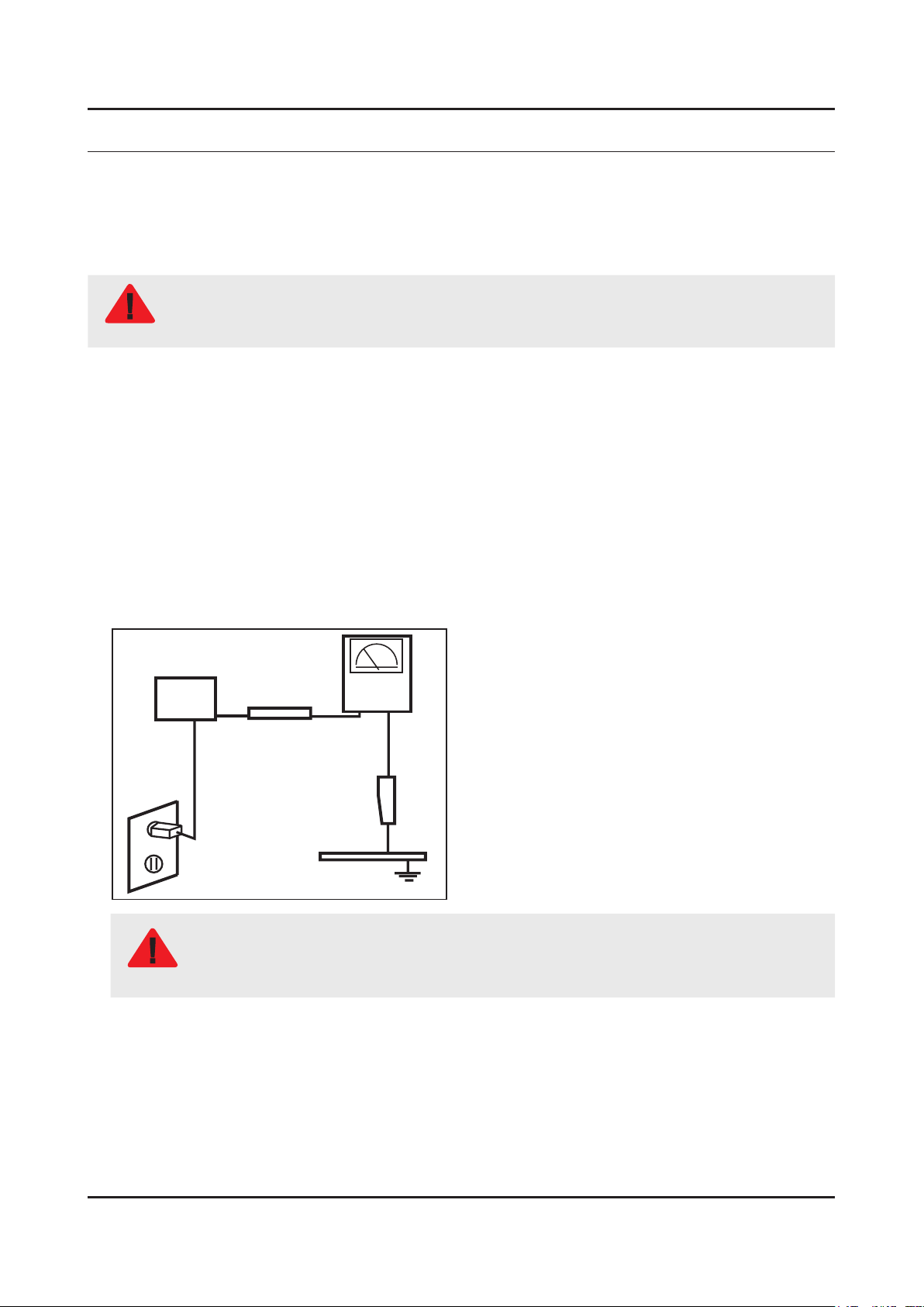
Leakage Current Hot Check:3.
Disconnect the AC power and DC power jack before servicing.
(READING SHOULD)
DEVICE
UNDER
TEST
ALSO TEST WITH
PLUG REVERSED
(USING AC ADAPTER
PLUG AS REQUIRED)
NOT BE ABOVE 0.5mA
2-WIRE CORD
TEST ALL
EXPOSED METAL
SURFACES
LEAKAGE
CURRENT
TESTER
EARTH
GROUND
Do not use an isolation transformer during this test.
Use a leakage current tester or a metering system that complies with American National Standards
WARNING
Institute (ANSI C101.1, Leakage Current for Appliances), and Underwriters Laboratories (UL
Publication UL1410, 59.7).
With the unit completely reassembled, plug the AC line cord directly into a 120V AC outlet. With the unit’s AC switch rst 4.
in the ON position and then OFF, measure the current between a known earth ground (metal water pipe, conduit, etc.)
and all exposed metal parts, including: metal cabinets, screwheads and control shafts.
The current measured should not exceed 0.5 milliamp.
Reverse the power-plug prongs in the AC outlet and repeat the test.
1-1

1-2
1. Precautions
1-1-4. Product Safety Notices
Some electrical and mechanical parts have special safetyrelated characteristics which are often not evident from visual
inspection. The protection they give may not be obtained by replacing them with components rated for higher voltage,
wattage, etc. Parts that have special safety characteristics are identied by
replacement that does not have the same safety characteristics as the recommended replacement part might create
shock, re and/or other hazards. Product safety is under review continuously and new instructions are issued whenever
appropriate.
on schematics and parts lists. A substitute
1-3
1. Precautions
1-2. Servicing Precautions
An electrolytic capacitor installed with the wrong polarity might explode.
WARNING
Before servicing units covered by this service manual, read and follow the Safety Precautions section of
CAUTION
NOTE
1-2-1. General Servicing Precautions
Always unplug the unit’s AC power cord from the AC power source and disconnect the DC Power Jack before 1.
attempting to: (a) remove or reinstall any component or assembly, (b) disconnect PCB plugs or connectors, (c) connect
a test component in parallel with an electrolytic capacitor.
Some components are raised above the printed circuit board for safety. An insulation tube or tape is sometimes used. 2.
The internal wiring is sometimes clamped to prevent contact with thermally hot components. Reinstall all such elements
to their original position.
After servicing, always check that the screws, components and wiring have been correctly reinstalled. Make sure that 3.
the area around the serviced part has not been damaged.
Check the insulation between the blades of the AC plug and accessible conductive parts (examples: metal panels, input 4.
terminals and earphone jacks).
Insulation Checking Procedure: Disconnect the power cord from the AC source and turn the power switch ON. Connect 5.
an insulation resistance meter (500 V) to theblades of the AC plug. The insulation resistance between each blade of the
AC plug and accessible conductive parts (see above) should be greater than 1 megohm.
Always connect a test instrument’s ground lead to the instrument chassis ground before connecting the positive lead; 6.
always remove the instrument’s ground lead last.
this manual.
If unforeseen circumstances create conict between the following servicing precautions and any of the
safety precautions, always follow the safety precautions.
1-4
1. Precautions
1-3. Static Electricity Precautions
Some semiconductor (solid state) devices can be easily damaged by static electricity. Such components are commonly
called Electrostatically Sensitive Devices (ESD). Examples of typical ESD are integrated circuits and some eld-effect
transistors. The following techniques will reduce the incidence of component damage caused by static electricity.
Immediately before handling any semiconductor components or assemblies, drain the electrostatic charge from your 1.
body by touching a known earth ground. Alternatively, wear a discharging wrist-strap device. To avoid a shock hazard,
be sure to remove the wrist strap before applying power to the monitor.
After removing an ESD-equipped assembly, place it on a conductive surface such as aluminum foil to prevent 2.
accumulation of an electrostatic charge.
Do not use freon-propelled chemicals. These can generate electrical charges sufcient to damage ESDs.3.
Use only a grounded-tip soldering iron to solder or desolder ESDs.4.
Use only an anti-static solder removal device. Some solder removal devices not classied as “anti-static” can generate 5.
electrical charges sufcient to damage ESDs.
Do not remove a replacement ESD from its protective package until you are ready to install it. Most replacement ESDs 6.
are packaged with leads that are electrically shorted together by conductive foam, aluminum foil or other conductive
materials.
Immediately before removing the protective material from the leads of a replacement ESD, touch the protective material 7.
to the chassis or circuit assembly into which the device will be installed.
Be sure no power is applied to the chassis or circuit and observe all other safety precautions.
CAUTION
Minimize body motions when handling unpackaged replacement ESDs. Motions such as brushing clothes together, or 8.
lifting your foot from a carpeted oor can generate enough static electricity to damage an ESD.
1-5
1. Precautions
1-4. Installation Precautions
For safety reasons, more than a people are required for carrying the product.1.
Keep the power cord away from any heat emitting devices, as a melted covering may cause re or electric shock.2.
Do not place the product in areas with poor ventilation such as a bookshelf or closet. The increased internal temperature 3.
may cause re.
Bend the external antenna cable when connecting it to the product. This is a measure to protect it from being exposed 4.
to moisture. Otherwise, it may cause a re or electric shock.
Make sure to turn the power off and unplug the power cord from the outlet before repositioning the product. Also check 5.
the antenna cable or the external connectors if they are fully unplugged. Damage to the cord may cause re or electric
shock.
Keep the antenna far away from any high-voltage cables and install it rmly. Contact with the highvoltage cable or the 6.
antenna falling over may cause re or electric shock.
When installing the product, leave enough space (0.4m) between the product and the wall for ventilation purposes. 7.
A rise in temperature within the product may cause re.
If an equipment is provided with a replaceable battery, and if replacement by an incorrect type could result in an 8.
explosion (for example, with some lithium batteries), the following applies:
Risk of explosion if battery is replaced by an incorrect type dispose of used batteries according to •
the instructions.
Do not dispose of batteries in a re.•
Do not short circuit, disassemble or overheat the batteries.•
CAUTION
Danger of explosion if battery is incorrectly replaced. Replace only with the same or equivalent •
type.
Do not be exposed to excessive heat such as sunshine, re or the like.•
2. Product Specications
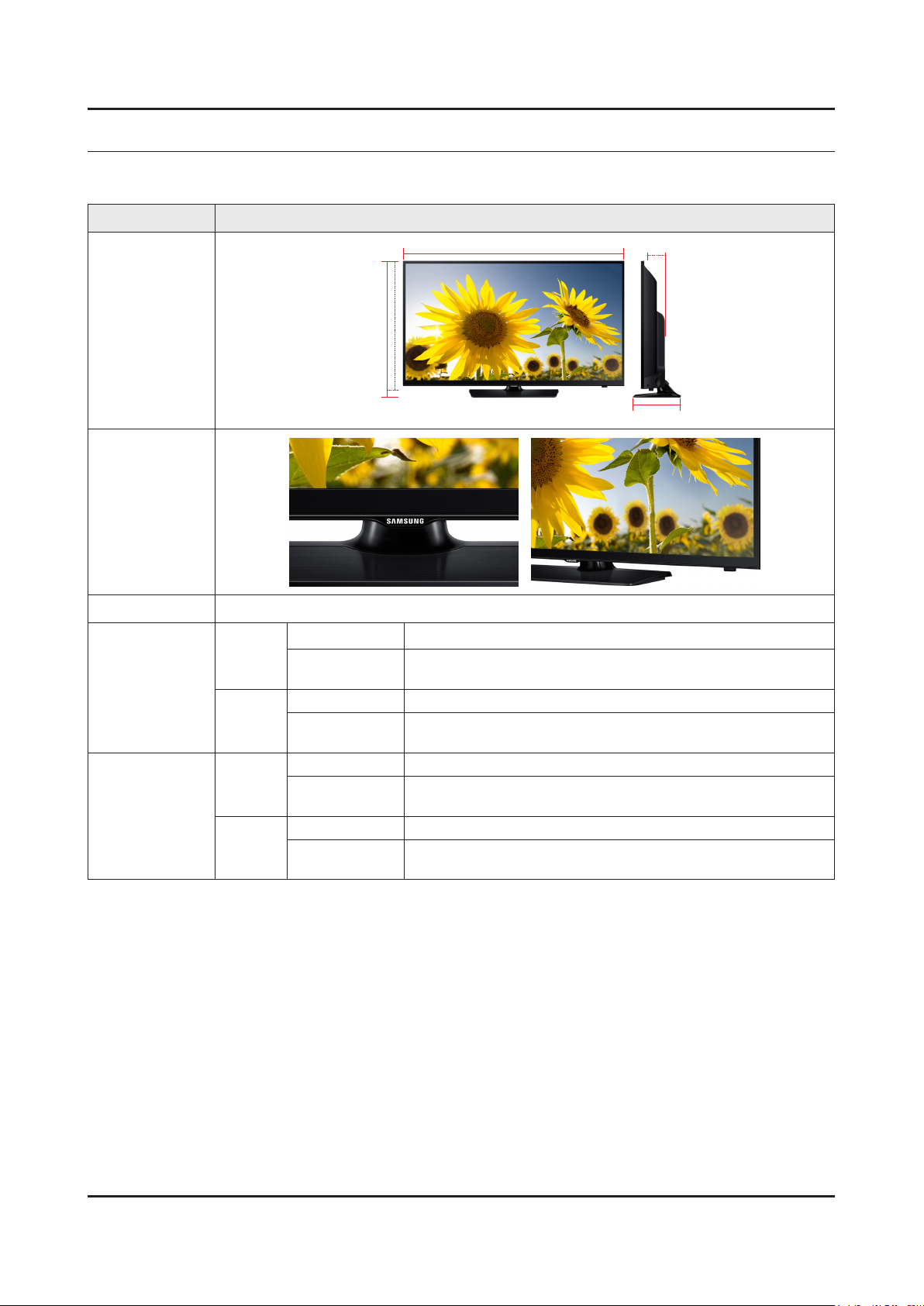
2-1. Product information
Model UN**H4203AH
2. Product specications
W
Stand
Stand
Stand
Stand
H
* W : Width H : High D : Depth
914.2 x 547.9 x 90.9 mm / 36.0 x 21.6 x 3.6 inches
1083.2 x 637.8 x 90.9 mm / 42.6 x 25.1 x 3.6 inches
Front View
Detail View
Front Color Black (Panel)
Set with Stand 914.2 x 586.4 x 196.4 mm / 36.0 x 23.1 x 7.7 inches
40H42
Dimensions
W x H x D
48H42
40H42
Weight
48H42
Set without
Set with Stand 1083.2 x 677.0 x 203.9 mm / 42.6 x 26.6 x 8.0 inches
Set without
Set with Stand 7.6 kg / 16.8 lbs
Set without
Set with Stand 9.9 kg / 21.8 lbs
Set without
D
7.0 kg / 15.4 lbs
9.1 kg / 20.0 lbs
2-1
2-2
2. Product specications
2-2. Product specication
2-2-1. Detailed Specications
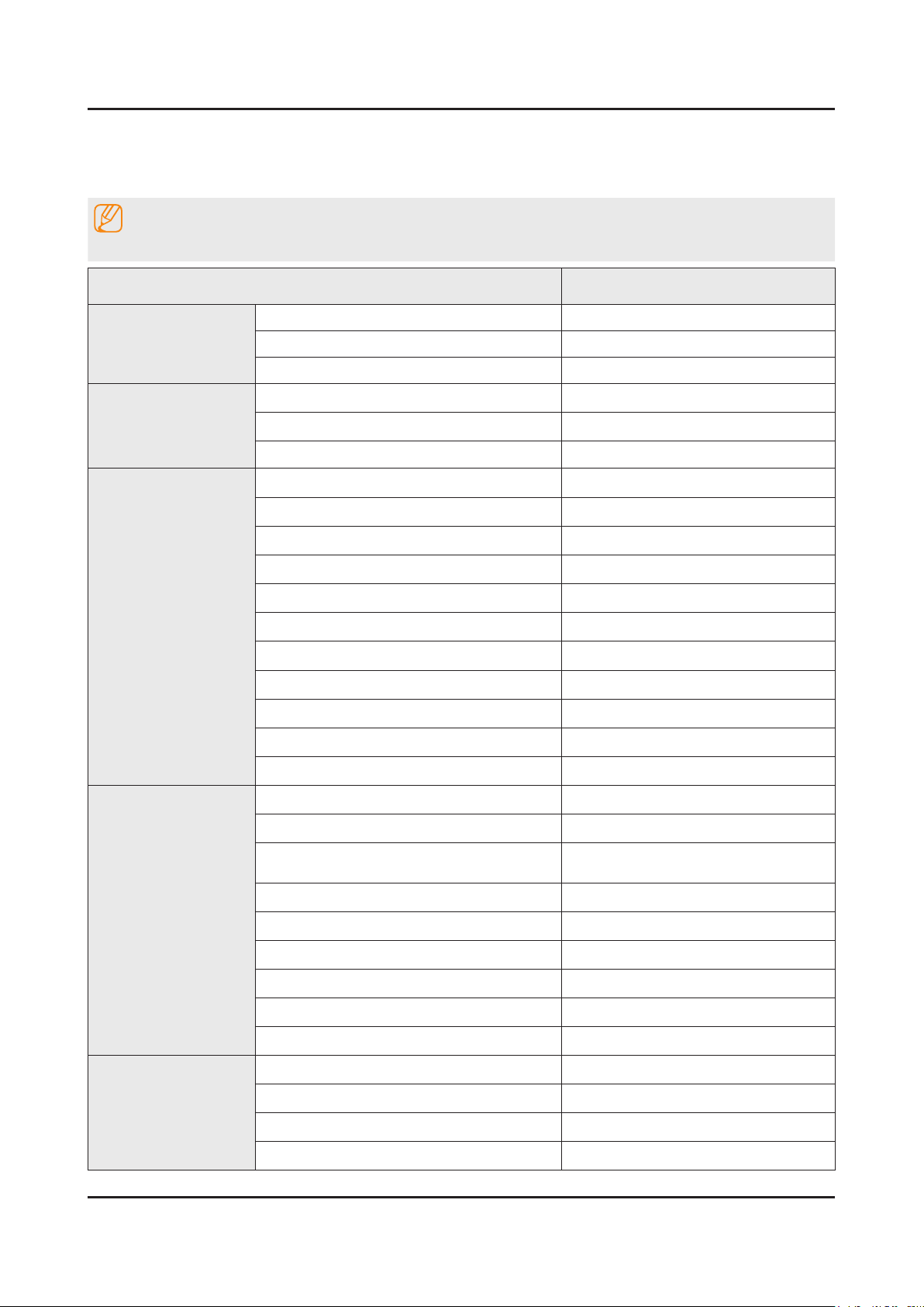
NOTE
Design and specications are subject to change without prior notice.
Item UN**H4203AHXPA
General Information
Display
Video
Product LED
Series 4
Country PANAMA
Screen Size 40"/48"
Resolution 1366 X 768
Ultra Clear Panel N/A
Picture Engine HyperReal Engine
Clear Motion Rate 120
Dynamic Contrast Ratio Mega Contrast
Micro Dimming No
Precision Black (Local Dimming) N/A
Wide Color Enhancer (Plus) Yes
Wide Color Gamut N/A
Color Accuracy N/A
Auto Depth Enhancer N/A
Film Mode Yes
Audio
Smart TV
Natural Mode Support N/A
Dolby MS10 / MS110 Dolby MS10
DTS Studio Sound / DNSe+ DTS Studio Sound
DTS Premium Sound / DTS Premium Sound
5.1
3D Sound N/A
Auto Volume Leveler Yes
Sound Output (RMS) 10W x 2
Speaker Type Down Firing + Full Range
Woofer N/A
HD Audio N/A
Smart Hub Yes
Samsung SMART TV Yes
On TV N/A
Movies & TV Shows N/A
DTS Premium Sound 5.1

2-3
2. Product specications
Item UN**H4203AHXPA
Smart TV
Smart Interaction
Multimedia N/A
Apps Yes
News On N/A
Game N/A
My Space N/A
Social N/A
Fitness N/A
Kids N/A
Multi-Screen (Dual / Quad Screen) N/A
Skype™ on Samsung TV N/A
Web Browser Yes
AllShare Control Yes
Search Yes
Voice Interaction N/A
Voice Control N/A
Camera Built-in N/A
Smart Convergence
Tuner/Broadcasting
Connectivity
Face recognition N/A
Motion control N/A
Contents Streaming Yes
Screen Mirroring Yes
Samsung SMART View N/A
Smart Home N/A
Wake On LAN N/A
WiDi N/A
DTV Tuner ISDB-T / DVB-T
Analog Tuner Yes (Trinorma)
MHP / MHEG / HbbTV / ACAP / GINGA /
OHTV
HDMI 2
USB 1
Component In (Y/Pb/Pr) 1
Composite In (AV) 1 (Common Use for Component Y)
Ethernet (LAN) Yes
No
Headphone N/A
Audio Out (Mini Jack) Yes
Digital Audio Out (Optical) 1
2-4
2. Product specications
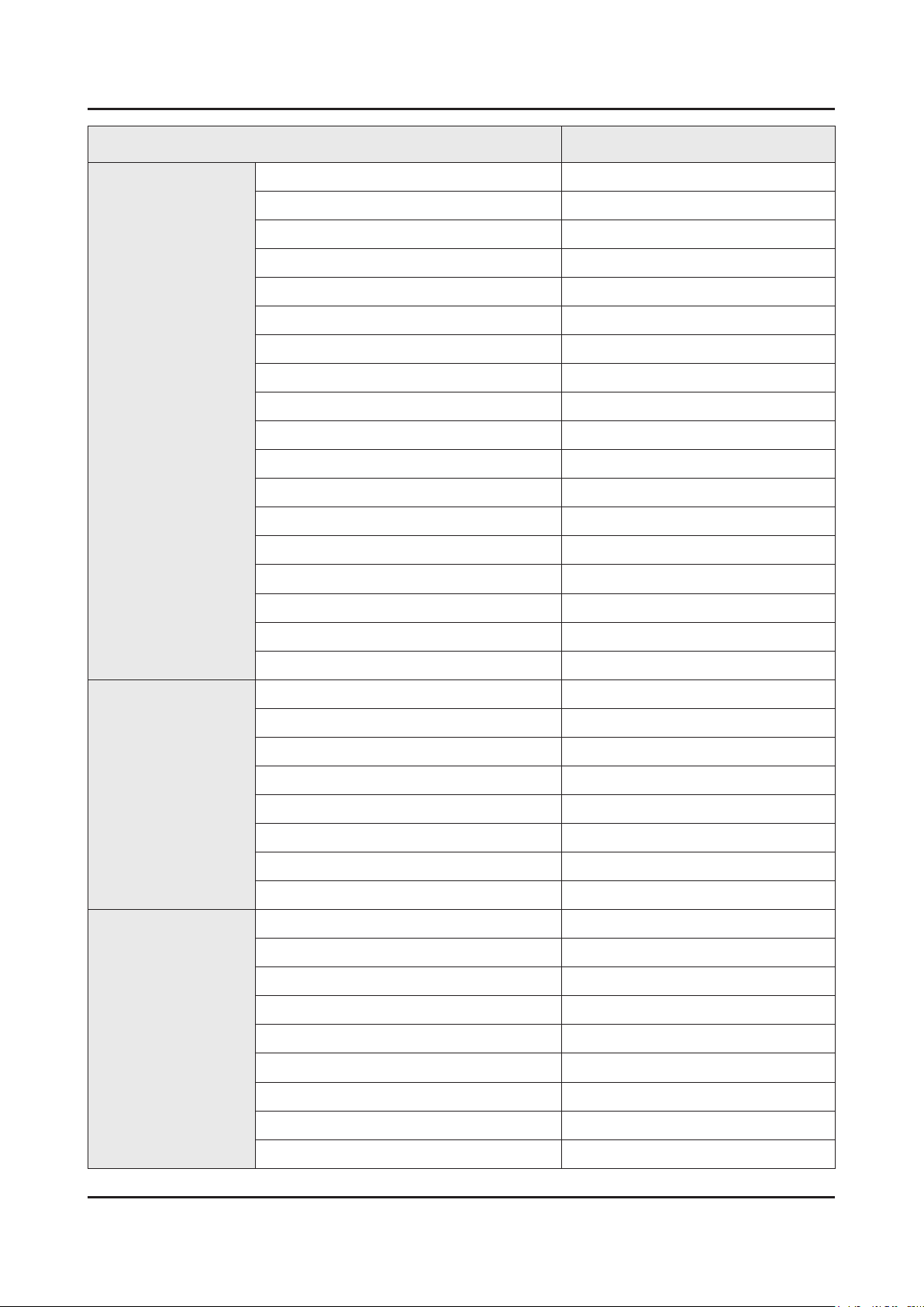
Item UN**H4203AHXPA
Connectivity
PC In (D-sub) N/A
PC/DVI Audio In (Mini Jack) N/A
RF In (Terrestrial / Cable input / Satellite input) 1/1/0
Ex-Link ( RS-232C ) N/A
IR Out N/A
CI Slot N/A
Scart N/A
MHL 3 N/A
One Connect (Jack) N/A
WiFi Direct Yes
MHL N/A
Dongle Ready (3G / LTE) N/A
HDMI 1.4 3D Auto Setting N/A
HDMI 1.4 A/Return Ch. Support N/A
InstaPort S (HDMI quick switch) N/A
Wireless LAN Adapter Support No
Design
Additional Feature
Wireless LAN Built-in Yes
Anynet+ (HDMI-CEC) N/A
Design Narrow Bezel
Bezel Type NNB
Slim Type Normal
Front Color Black
Light Effect (Deco) No
Stand Type Square
Swivel (Left/Right) No
Camera Type N/A
Samsung 3D N/A
3D Converter N/A
Instant On N/A
N-KIT N/A
Quad Core+ N/A
Accessibility Yes(Zoom)
Digital Clean View Yes
Auto Channel Search Yes
Auto Power Off Yes
2-5
2. Product specications
Item UN**H4203AHXPA
Additional Feature
Clock&On/Off Timer Yes
Sleep Timer Yes
BD Wise Plus N/A
Caption (Subtitle) Yes
ConnectShare™ (USB 2.0) Movie
AC/DC TV N/A
Sports Mode Basic
Screen Capture N/A
Sound Capture N/A
Embeded POP Yes
EPG Yes
Extended PVR N/A
Game Mode Yes
History N/A
Multiroom Compatible N/A
OSD Language Local Languages
Eco Feature
Accessory
Picture-In-Picture Yes
USB HID Support Yes
Smart Evolution Support N/A
TV SoundConnect N/A
Teletext (TTXT) N/A
Time Shift N/A
Analog Clean View No
Triple Protector N/A
GUI Golden Bridge
Eco Mark .
Eco Label No
Eco Sensor Yes
Energy Efciency Class N/A
Mercury Content 0.0 mg
Lead Presence Yes
3D Active Glasses (Included) N/A
Remote Controller Model TM1250A
Batteries (for Remote Control) Yes
Samsung Smart Touch Control (Included) N/A
2-6
2. Product specications
Item UN**H4203AHXPA
Accessory
Electric Stand Support N/A
Electric Wall Mount Support N/A
Ultra Slim Wall Mount Supported N/A
Mini Wall Mount Supported Yes
Vesa Wall Mount Supported Yes
Floor Stand Support N/A
TV Camera (Included) N/A
IR Extender Cable (Included) No
Network Speaker (Included) N/A
Wireless Keyboard (Included) N/A
Wireless LAN Adaptor (Included) N/A
User Manual Yes
E-Manual Yes
ANT-Cable N/A
Power Cable Yes
Slim Gender Cable N/A
2-7
2. Product specications
2-2-2. Specications
Specications
Model UN**H4203AH
Item Description
Screen Size (Diagonal) 40 inches 48 inches
LCD Panel HD 60 Hz
Display Colors 16.7 M color
Display Resolution 1,366 x 768
Input Signal Analog 0.7 Vp-p ± 5% positive at 75Ω, internally terminated
Input Sync Signal H/V Separate, TTL, P. or N.
AC Power Voltage & Frequency AC100-240V 50/60Hz
Sound (Output) 20 W (10 W X 2)
2. Product specications
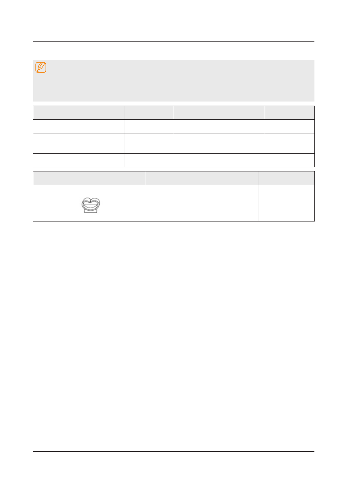
2-3. Accessories
NOTE
The items’ colors and shapes may vary depending on the model.•
Cables not included in the package contents can be purchased separately.•
The part code for some accessories may differ depending on your region.•
Product Code. No Product Code. No
Remote Control• BN59-01178K User Manual• BN68-06549A
Batteries (AAA x 2)• 4301-000121
Power Cord• 3903-000853
Image Product Code. No
Holder-Wire Stand• BN61-08370A
Warranty Card (Not available •
in some locations)
AA68-03727A
2-8
3. Disassembly and Reassemble
3. Disassembly and Reassembly
This section of the service manual describes the disassembly and reassembly procedures for the LED TV.
This LED TV contains electrostatically sensitive devices. Use caution when handling these components.
WARNING
3-1. Disassembly and Reassembly
Disconnect the LED TV from the power source before disassembly.1.
Follow these directions carefully; never use metal instruments to pry apart the cabinet.2.
CAUTION
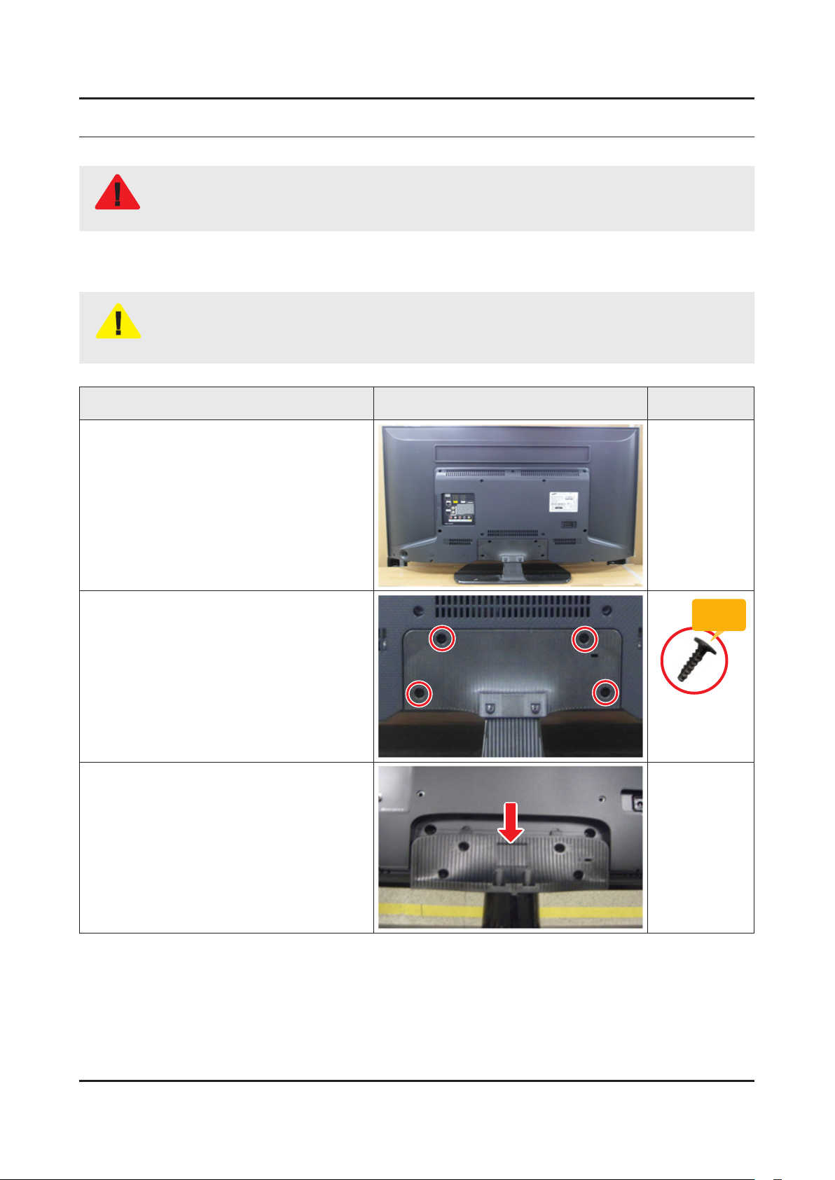
Place TV face down on cushioned table.
If there is no additional coment, it is same for all inches.3.
Description Picture Description Screws
1
Remove 4 screws from the stand.
2
Remove stand.
3
Torque :
9~ 10Kgf.cm
6003-001782
3-1
3-2
3. Disassembly and Reassemble
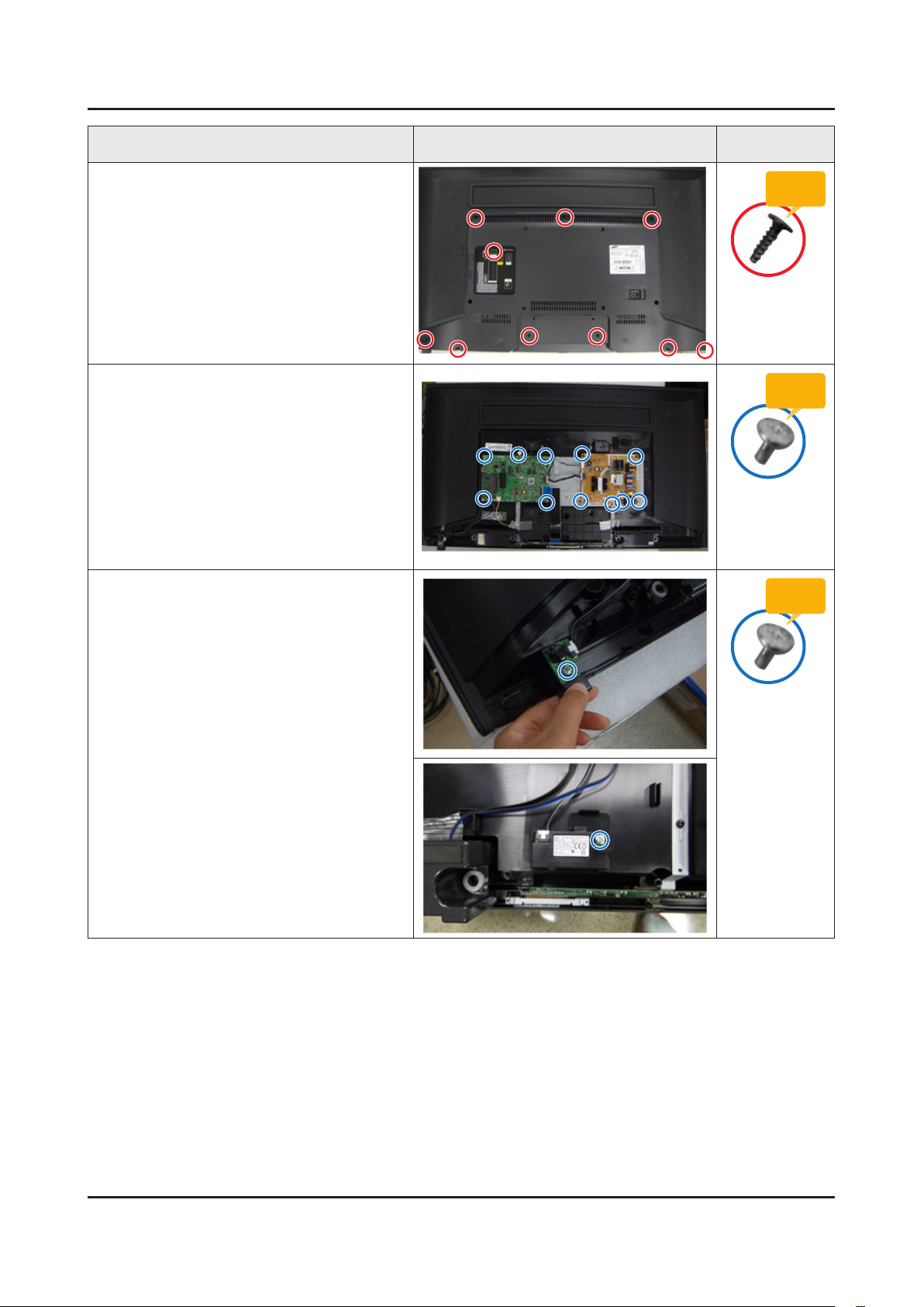
Description Picture Description Screws
Remove screws of rear cover.
4
Disconnect the function assy cable.
5
Remove the screws of Function module &
6
WiFi.
Torque :
9~ 10Kgf.cm
6003-001782
Torque :
7~ 8Kgf.cm
6003-001188
Torque :
7~ 8Kgf.cm
6003-001188
3-3
3. Disassembly and Reassemble
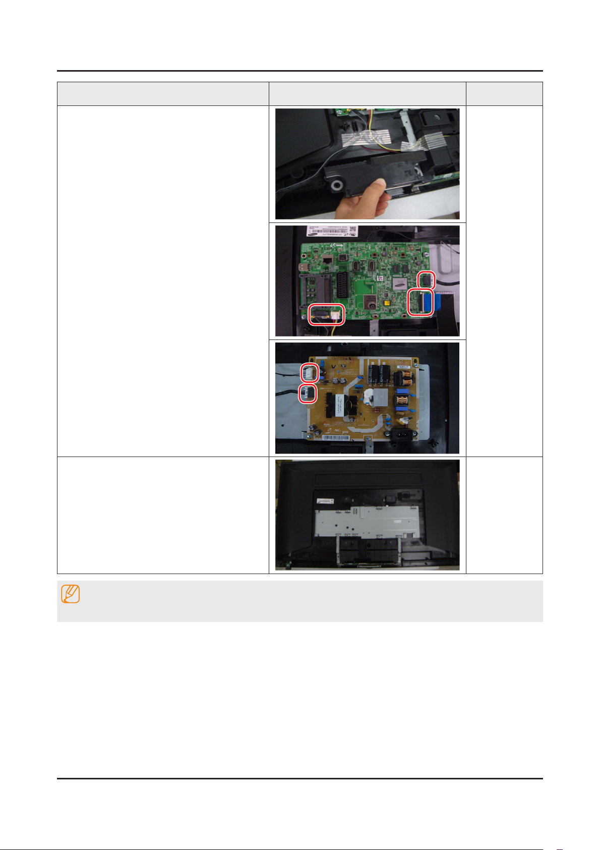
Description Picture Description Screws
Remove the speakers and cables.
7
Completed disassembly.
8
NOTE
Reassembly procedures are in the reverse order of disassembly procedures.
3-4
3. Disassembly and Reassemble
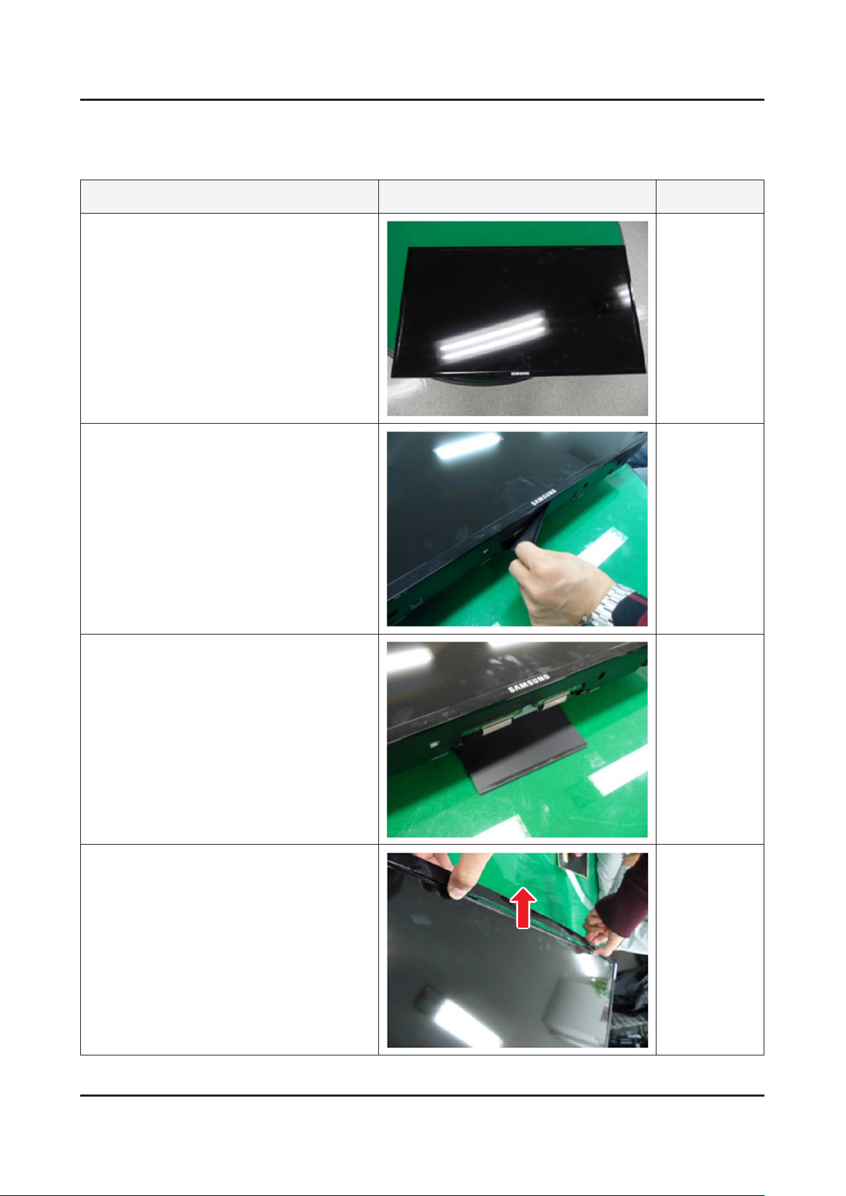
3-2. Disassembly(PTC)
How to disassembly
Description Picture Description Refer
Place TV face up on cushioned table.
1
Remove the T-CON Cover
2
3
First spread the PTC upper
4
 Loading...