

Page 1
UN46C6500VFXZA
http://gspn3.samsungcsportal.com
Fast Track Troubleshooting Manual Rev –1/12/12
SERVICE BULLETINS
ASC20110621002
2010 LED Option Byte Table. It is
SMPS
important to verify the correct
option byte is set.
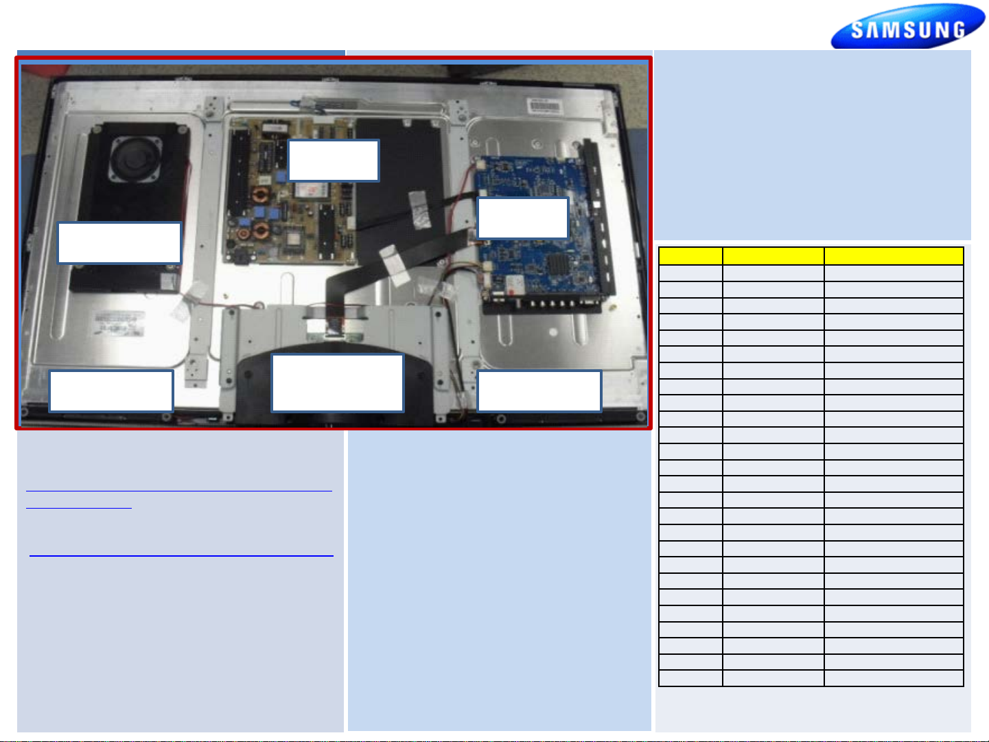
Insert Photo of TV Board Layout
Include Board Assy names (as appearing in parts) and any
Woofer
special labels/items (i.e. Plasma voltage label)
Speaker
HELP : 1-888-751-4086 (Tech Support)
1-866-894-0637 (FE)
GSPN
PLUS ONE
http://my.plus1solutions.net/clientPortals/samsung
HOT TIPS
Power On Problems: (see page 2)
Video Problems: (see page 3.4)
Other:
HDMI Bleed-over
T-CON
(below Bracket)
2/21/2011
(T-VALAUSC, 1035.0)
Reason: Support Netflix 2.1 and MLB.tv
apps. Support new TV camera (Model:
CY-STC1100). Add "3D Optimize" option
on Menu for better 3D image.(Only
LCD/LED TV)
Previous: 1032.0
Prevents :
-USB Power Overload' message pops up
even USB port is not connected
-Plug & Play is displayed upon power up.
Please check Samsung.com for latest update!
Main
Speaker
FIRMWARE
Please check GSPN for parts update!
Version Parts No Short Description
ALL BN44-00356A SMPS
SQ01 BN94-03370F Main PCB
HQ03 BN94-03370Q Main PCB
H304 BN94-03370Q Main PCB
CN02 BN94-03370X Main PCB
HQ03 BN94-03370Y M ain PC B
AA05 BN94-04684C Main PCB
ALL BN96-15397C Function & IR PCB
CN02 BN07-00854A Panel
SQ01 BN07-00860A Panel
AA05 BN07-00934A Panel
SQ01 BN81-04355A T-CON PCB
CN02 BN81-04456A T-CON PCB
H304 BN81-05772A T-CON PCB
HQ03 BN81-05772A T-CON PCB
HQ03 BN95-00413A Panel
H304 BN95-00413B Panel
AA05 BN96-13687A T-CON PCB
ALL BN63-06543B Back Bottom Cover
ALL BN96-13131A Stand Guide
ALL BN96-13133A Stand Base
ALL BN96-13748A Front Cover
ALL BN96-13843A Rear Cover
ALL 3903-000527 Power Cord
ALL BN40-00162A Tuner
ALL BN96-12723M LVDS Cable
1
Page 2
UN46C6500VFXZA
Fast Track Troubleshooting Manual
C
S
N
I
2
G.
0
1
1 B12V 10 GND
2 A5V 11 GND
P
S
I
I
N
G.
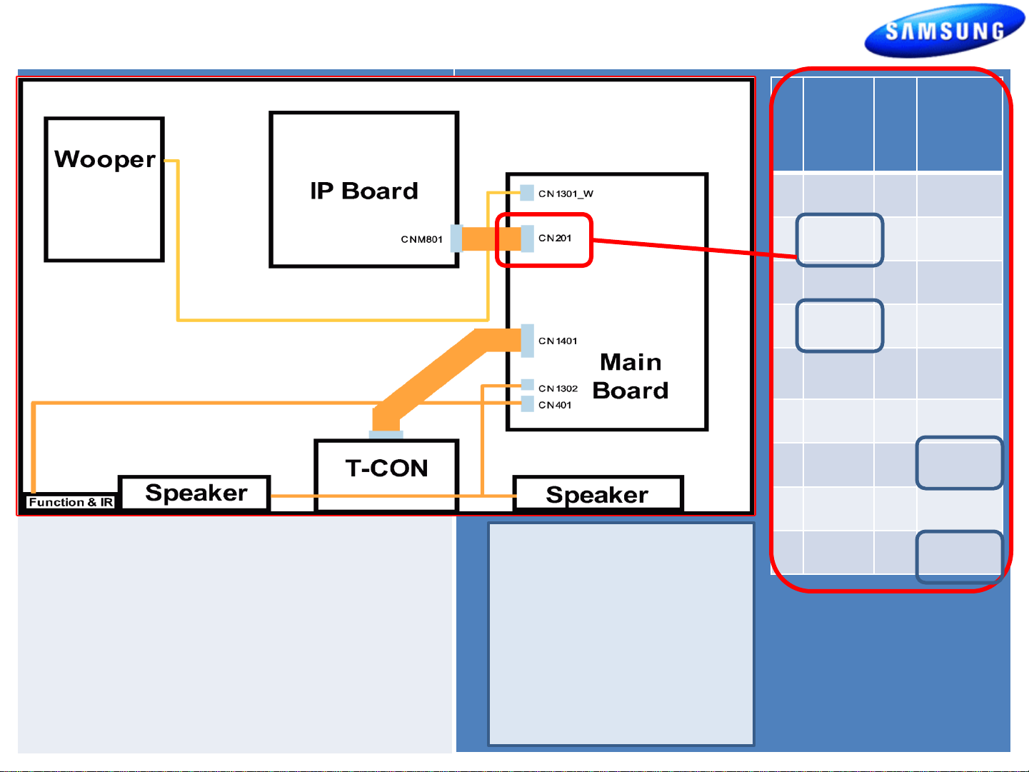
Wiring Diagram
Include Connector Numbers , References, and
LVDS
Locations.
Cable
Power On Sequence:
1. Standby Voltages: CN201-2, 4 (5V)
2. Power On probable error on CN201-2
or 4 PS_ON )
3. Low Voltage Supplies On CN201-
To Force Backlight On
without Main Board :
1. Remove Power Cord
2. Disconnect CN201
3. Plug In Power Cord
3 B12V 12 H_OUT
4 A5V 13 B13V
5 B5V 14 PWM
Dimming
6 B5V 15 B13V
7 B5V 16 B5V
8 GND 17 B13V
9 GND 18 IP_DET
5,6,7,13,17
4. Back Light Supply On CN201 -16
5. Back Light Confirmation CN201-18
4. Backlight should be
on immediately.
2
Page 3

Fast Track Troubleshooting Manual
1. Verify Video Operation
a. Customer Picture Test (models available)
b. “Display” (If display is OK source is suspected)
C. Substitute with known good Source
(external DVD or Signal Generator)
2. Using Test Patterns in Service Mode
- ENTER SERVICE MODE –
1. Select an active source signal. (HDMI preferred)
Test Pattern may rely on signal source to appear.
Customer Remote Service Remote
2. Power off 2. Power On
3. Mute, 182, Power 3. Info, Factory
2010 Models
FBE
FRC
1.Check OSD & Customer Picture Test.
2. Access SVC Mode (with source signal)
3. Activate FBE Test Patterns & Verify.
4. Activate FRC Test Patterns & Verify.
2011 LED 8000 SeriesTROUBLESHOOTING VIDEO PROBLEMS
1. Select an active source signal. (HDMI preferred)
Test Pattern may rely on signal source to appear.
2. Access Service Mode
3. Access SVC
4. Access Test Patterns
5. Access Genoa-P
6. Check Test Patterns
7. If OK suspect input Source
8. Access Napoli
9. Check Test Patterns
10. If OK and Genoa-P was not good
Suspect Main Board or LVDS Cable
3
Page 4

ON SCREEN FAILURE EXAMPLES:
Fast Track Troubleshooting Manual
ALIGNMENTS:
1. Check/Set Option Bytes:
If Picture & Display errors
Defective Main Board, LVDS,
Green lines or a green screen
defective main board , LVDS , or
T-CON.
or T-CON
Pixelization can be caused by the main board
but is more commonly a source error
Vertical or Horizontal Lines :Defective
Panel likely but also T-CON, LVDS, or Main
Board. Use Test Patterns in Factory Service
Mode to determine error)
2. Check/Perform Firmware Upgrade for
all repairs.
3. Perform reset in Service Mode &
Plug and Play if Main board is replaced.
SPECIAL NOTES:
Inform customer of reset of all
Settings if Main Board or Panel is replaced.
Option
Type Model Tuner Region DDR Light Effect
46A1UF0E UC6500 SEMCO - - OFF - - USA W-Violet - 46D1UF0E UC6500 SEMCO - - OFF - - USA W-Violet - 46A1UF0E UC6500 SEMCO - - OFF - - USA W-Violet - 46A1UF0E UC6500 SEMCO - - OFF - - USA W-Violet - -
46L1UF0E UC6500 SEMCO - OFF - USA W-Violet
46A1UF0E UC6500 SEMCO - - OFF - - USA W-Violet - -
46L1UF0E UC6500 SEMCO - OFF - USA W-Violet
46D1UF0E UC6500 SEMCO - - OFF - - USA W-Violet - -
Audio
AMP
Ch Table Country Front Color
Local
Set
Exhibition
Mode
4
 Loading...