

Page 1

LED TV
Chassis : U8LA
Model : UN40H5003AF
SERVICE
LED TV Contents
1. Precautions
2. Product specications
3. Disassembly and Reassembly
4. Troubleshooting
5. Wiring Diagram
Manual
UN40H5003AF
Page 2

Contents
1. Precautions ...................................................................................................................1-1
1-1. Safety Precautions ..............................................................................................................1-1
1-1-1. Warnings ...................................................................................................................1-1
1-1-2. Servicing the LED TV ...............................................................................................1-1
1-1-3. Fire and Shock Hazard .............................................................................................1-1
1-1-4. Product Safety Notices .............................................................................................1-2
1-2. Servicing Precautions ..........................................................................................................1-3
1-2-1. General Servicing Precautions ................................................................................. 1-3
1-3. Static Electricity Precautions ...............................................................................................1-4
1-4. Installation Precautions .......................................................................................................1-5
2. Product Specications.................................................................................................2-1
2-1. Product information .............................................................................................................2-1
2-2. Product specication ...........................................................................................................2-2
2-2-1. Detailed Specications ............................................................................................. 2-2
2-2-2. Feature & Specications ........................................................................................... 2-6
2-3. Accessories ........................................................................................................................2-7
3. Disassembly and Reassembly ....................................................................................3-1
3-1. Disassembly and Reassembly ............................................................................................3-1
3-2. Disassembly(PTC) ...............................................................................................................3-4
4. Troubleshooting ...........................................................................................................4-1
4-1. Troubleshooting ...................................................................................................................4-1
4-1-1. Previous Check ........................................................................................................4-1
4-2. How to Check Fault Symptom .............................................................................................4-2
4-3. Factory Mode Adjustments ................................................................................................4-10
4-3-1. Detail Factory Option ..............................................................................................4-10
4-3-2. Entering Factory Mode ........................................................................................... 4-11
4-3-3. Factory Data ...........................................................................................................4-12
4-4. White Balance ...................................................................................................................4-15
4-4-1. Calibration ..............................................................................................................4-15
4-4-2. Service Adjustment ................................................................................................. 4-15
4-4-3. Adjustment .............................................................................................................. 4-17
4-5. Software Upgrade ..............................................................................................................4-18
4-5-1. By USB ...................................................................................................................4-18
4-5-2. By Online ................................................................................................................4-18
4-5-3. Alternative Software (Backup) ................................................................................ 4-18
4-6. Rear Cover Dimension ......................................................................................................4-19
4-6-1. UN40H5003 Cover Rear Dimension ......................................................................4-19
5. Wiring Diagram .............................................................................................................5-1
5-1. Wiring Diagram ....................................................................................................................5-1
5-2. Connector ............................................................................................................................5-2
5-3. Connector Functions ...........................................................................................................5-4
5-4. Cables .................................................................................................................................5-5
Page 3

This Service Manual is a property of Samsung Electronics Co.,Ltd.
Any unauthorized use of Manual can be punished under applicable
International and/or domestic law.
© 2014 Samsung Electronics Co.,Ltd.
All rights reserved.
Printed in Korea
Page 4
1. Precautions
1. Precautions
1-1. Safety Precautions
Follow these safety, servicing and ESD precautions to prevent damage and to protect against potential hazards such as
electrical shock.
1-1-1. Warnings
For continued safety, do not attempt to modify the circuit board.
WARNING
1-1-2. Servicing the LED TV
When servicing the LED TV, Disconnect the AC line cord from the AC outlet.1.
It is essential that service technicians have an accurate voltage meter available at all times. Check the calibration of this 2.
meter periodically.
1-1-3. Fire and Shock Hazard
Before returning the monitor to the user, perform the following safety checks:
Inspect each lead dress to make certain that the leads are not pinched or that hardware is not lodged between the 1.
chassis and other metal parts in the monitor.
Inspect all protective devices such as nonmetallic control knobs, insulating materials, cabinet backs, adjustment and 2.
compartment covers or shields, isolation resistorcapacitor networks, mechanical insulators, etc.
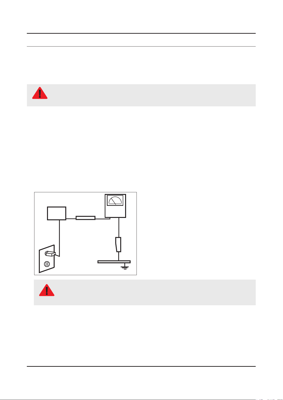
Leakage Current Hot Check:3.
Disconnect the AC power and DC power jack before servicing.
(READING SHOULD)
DEVICE
UNDER
TEST
ALSO TEST WITH
PLUG REVERSED
(USING AC ADAPTER
PLUG AS REQUIRED)
NOT BE ABOVE 0.5mA
2-WIRE CORD
TEST ALL
EXPOSED METAL
SURFACES
LEAKAGE
CURRENT
TESTER
EARTH
GROUND
Do not use an isolation transformer during this test.
Use a leakage current tester or a metering system that complies with American National Standards
WARNING
Institute (ANSI C101.1, Leakage Current for Appliances), and Underwriters Laboratories (UL
Publication UL1410, 59.7).
With the unit completely reassembled, plug the AC line cord directly into a 120V AC outlet. With the unit’s AC switch rst 4.
in the ON position and then OFF, measure the current between a known earth ground (metal water pipe, conduit, etc.)
and all exposed metal parts, including: metal cabinets, screwheads and control shafts.
The current measured should not exceed 0.5 milliamp.
Reverse the power-plug prongs in the AC outlet and repeat the test.
1-1
Page 5

1-2
1. Precautions
1-1-4. Product Safety Notices
Some electrical and mechanical parts have special safetyrelated characteristics which are often not evident from visual
inspection. The protection they give may not be obtained by replacing them with components rated for higher voltage,
wattage, etc. Parts that have special safety characteristics are identied by
replacement that does not have the same safety characteristics as the recommended replacement part might create
shock, re and/or other hazards. Product safety is under review continuously and new instructions are issued whenever
appropriate.
on schematics and parts lists. A substitute
Page 6

1-3
1. Precautions
1-2. Servicing Precautions
An electrolytic capacitor installed with the wrong polarity might explode.
WARNING
Before servicing units covered by this service manual, read and follow the Safety Precautions section of
CAUTION
NOTE
1-2-1. General Servicing Precautions
Always unplug the unit’s AC power cord from the AC power source and disconnect the DC Power Jack before 1.
attempting to: (a) remove or reinstall any component or assembly, (b) disconnect PCB plugs or connectors, (c) connect
a test component in parallel with an electrolytic capacitor.
Some components are raised above the printed circuit board for safety. An insulation tube or tape is sometimes used. 2.
The internal wiring is sometimes clamped to prevent contact with thermally hot components. Reinstall all such elements
to their original position.
After servicing, always check that the screws, components and wiring have been correctly reinstalled. Make sure that 3.
the area around the serviced part has not been damaged.
Check the insulation between the blades of the AC plug and accessible conductive parts (examples: metal panels, input 4.
terminals and earphone jacks).
Insulation Checking Procedure: Disconnect the power cord from the AC source and turn the power switch ON. Connect 5.
an insulation resistance meter (500 V) to theblades of the AC plug. The insulation resistance between each blade of the
AC plug and accessible conductive parts (see above) should be greater than 1 megohm.
Always connect a test instrument’s ground lead to the instrument chassis ground before connecting the positive lead; 6.
always remove the instrument’s ground lead last.
this manual.
If unforeseen circumstances create conict between the following servicing precautions and any of the
safety precautions, always follow the safety precautions.
Page 7
1-4
1. Precautions
1-3. Static Electricity Precautions
Some semiconductor (solid state) devices can be easily damaged by static electricity. Such components are commonly
called Electrostatically Sensitive Devices (ESD). Examples of typical ESD are integrated circuits and some eld-effect
transistors. The following techniques will reduce the incidence of component damage caused by static electricity.
Immediately before handling any semiconductor components or assemblies, drain the electrostatic charge from your 1.
body by touching a known earth ground. Alternatively, wear a discharging wrist-strap device. To avoid a shock hazard,
be sure to remove the wrist strap before applying power to the monitor.
After removing an ESD-equipped assembly, place it on a conductive surface such as aluminum foil to prevent 2.
accumulation of an electrostatic charge.
Do not use freon-propelled chemicals. These can generate electrical charges sufcient to damage ESDs.3.
Use only a grounded-tip soldering iron to solder or desolder ESDs.4.
Use only an anti-static solder removal device. Some solder removal devices not classied as “anti-static” can generate 5.
electrical charges sufcient to damage ESDs.
Do not remove a replacement ESD from its protective package until you are ready to install it. Most replacement ESDs 6.
are packaged with leads that are electrically shorted together by conductive foam, aluminum foil or other conductive
materials.
Immediately before removing the protective material from the leads of a replacement ESD, touch the protective material 7.
to the chassis or circuit assembly into which the device will be installed.
Be sure no power is applied to the chassis or circuit and observe all other safety precautions.
CAUTION
Minimize body motions when handling unpackaged replacement ESDs. Motions such as brushing clothes together, or 8.
lifting your foot from a carpeted oor can generate enough static electricity to damage an ESD.
Page 8
1-5
1. Precautions
1-4. Installation Precautions
For safety reasons, more than a people are required for carrying the product.1.
Keep the power cord away from any heat emitting devices, as a melted covering may cause re or electric shock.2.
Do not place the product in areas with poor ventilation such as a bookshelf or closet. The increased internal temperature 3.
may cause re.
Bend the external antenna cable when connecting it to the product. This is a measure to protect it from being exposed 4.
to moisture. Otherwise, it may cause a re or electric shock.
Make sure to turn the power off and unplug the power cord from the outlet before repositioning the product. Also check 5.
the antenna cable or the external connectors if they are fully unplugged. Damage to the cord may cause re or electric
shock.
Keep the antenna far away from any high-voltage cables and install it rmly. Contact with the highvoltage cable or the 6.
antenna falling over may cause re or electric shock.
When installing the product, leave enough space (0.4m) between the product and the wall for ventilation purposes. 7.
A rise in temperature within the product may cause re.
If an equipment is provided with a replaceable battery, and if replacement by an incorrect type could result in an 8.
explosion (for example, with some lithium batteries), the following applies:
Risk of explosion if battery is replaced by an incorrect type dispose of used batteries according to •
the instructions.
Do not dispose of batteries in a re.•
Do not short circuit, disassemble or overheat the batteries.•
CAUTION
Danger of explosion if battery is incorrectly replaced. Replace only with the same or equivalent •
type.
Do not be exposed to excessive heat such as sunshine, re or the like.•
Page 9
2. Product Specications
2-1. Product information
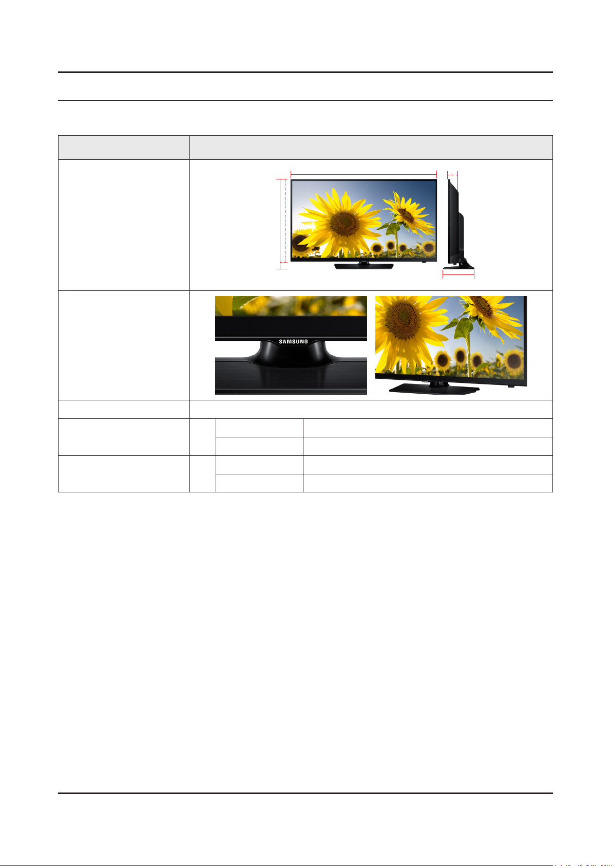
Model UN40H5003AF
2. Product specications
W
Front View
Detail View
Front Color Black
Dimensions
(W x H x D)
Weight 40"
40"
With Stand 918 x 592.6 x 227.6 mm
Without Stand 918 x 533.2 x 94 mm
With Stand 9.6 kg
Without Stand 7.6 kg
H
* W : Width H : High D : Depth
D
2-1
Page 10

2-2
2. Product specications
2-2. Product specication
2-2-1. Detailed Specications
NOTE
Design and specications are subject to change without prior notice.
Item UN40H5003AFXZA
General Information
Display
Video
Audio
Product LED
Series 5
Country UNITED STATES
Inch 40
Resolution 1,920 x 1,080
Ultra Clear Panel No
Clear Motion Rate 120
Micro Dimming No
Precision Black (Local Dimming) N/A
Wide Color Enhancer (Plus) Yes
Color Accuracy No
Auto Depth Enhancer No
Auto Motion Plus No
Film Mode Yes
Dolby MS10 / MS110 Dolby Digital Plus / Dolby Pulse
DTS Studio Sound / DNSe+ DTS Studio Sound
DTS Premium Sound / DTS Premium
Sound 5.1
3D Sound No
DTS Premium Audio
Smart TV
Auto Volume Leveler Yes
Sound Customizer No
Sound Output (RMS) 10W x 2
Speaker Type Down Firing + Full Range
Woofer No
HD Audio No
Smart Hub No
Samsung SMART TV No
On TV No
Movies & TV Shows No
Multimedia No
Apps No
Page 11

2-3
2. Product specications
Item UN40H5003AFXZA
Smart TV
Smart Interaction
Smart Convergence
Tuner/Broadcasting
Connectivity
Game No
Multi-Screen (Dual / Quad Screen) No
Web Browser No
Voice Interaction No
Camera Built-in No
Motion control No
Contents Streaming No
Screen Mirroring No
ISP Bound Service No
RUI No
RVU No
Samsung SMART View No
Smart Home No
DTV Tuner ATSC / Clear QAM
Analog Tuner Yes
HDMI 2
USB 1
Component In (Y/Pb/Pr) 1
Composite In (AV) 1 (Common Use for Component Y)
Ethernet (LAN) No
Headphone No
Audio Out (Mini Jack) No
Digital Audio Out (Optical) 1
PC In (D-sub) No
PC/DVI Audio In (Mini Jack) No
RF In (Terrestrial / Cable input / Satellite
input)
Ex-Link ( RS-232C ) No
One Connect (Jack) No
WiFi Direct No
MHL No
HDMI 1.4 3D Auto Setting No
HDMI 1.4 A/Return Ch. Support No
1
Wireless LAN Built-in No
Anynet+ (HDMI-CEC) No
Page 12

2-4
2. Product specications
Item UN40H5003AFXZA
Design
Additional Feature
Design High Glossy
Bezel Type 17.5mm
Light Effect (Deco) No
Stand Type Square
Swivel (Left/Right) No
Camera Type N/A
Samsung 3D No
3D Converter No
Instant On No
Quad Core+ No
Digital Clean View Yes
Auto Channel Search Yes
Auto Power Off Yes
Clock&On/Off Timer Yes
Sleep Timer Yes
BD Wise Plus No
Caption (Subtitle) Yes
AC/DC TV N/A
Embeded POP Yes
EPG No
Game Mode Yes
History No
IP Video Closed Caption No
OSD Language English, French, Spanish
Picture-In-Picture No
Multi Tasking No
BT HID Built-in No
USB HID Support No
Smart Evolution Support No
TV SoundConnect No
Teletext (TTXT) No
Time Shift No
Eco Feature
V-Chip Yes
Eco Label No
Eco Sensor No
Page 13
2-5
2. Product specications
Item UN40H5003AFXZA
Accessory
3D Active Glasses (Included) No
Remote Controller Model TM1240A
Batteries (for Remote Control) Yes
Samsung Smart Touch Control (Included) No
Ultra Slim Wall Mount Supported No
Mini Wall Mount Supported Yes
Vesa Wall Mount Supported Yes
IR Extender Cable (Included) No
Wireless Keyboard (Included) No
User Manual Yes
E-Manual No
Power Cable Yes
Slim Gender Cable No
Page 14
2-6
2. Product specications
2-2-2. Feature & Specications
Specications
Model UN40H5003AF
Item Description
Screen Size (Diagonal) 40 inches
LCD Panel FHD 60Hz
Display Colors 16.7M color
Display Resolution 1920 x 1080
Input Signal Analog 0.7 Vp-p ± 5% positive at 75Ω, internally terminated
Input Sync Signal H/V Separate, TTL, P. or N.
AC Power Voltage & Frequency AC110-120V 60Hz
Sound (Output) 20W (10W X 2)
Page 15
2-7
2. Product specications
2-3. Accessories
NOTE
The items’ colors and shapes may vary depending on the model.•
Cables not included in the package contents can be purchased separately.•
The part code for some accessories may differ depending on your region.•
Product Code. No Product Code. No
Remote Control• AA59-00666A Power Cord• 3903-000853
Batteries (AAA x 2)• 4301-000103 User Manual• BN68-05829P
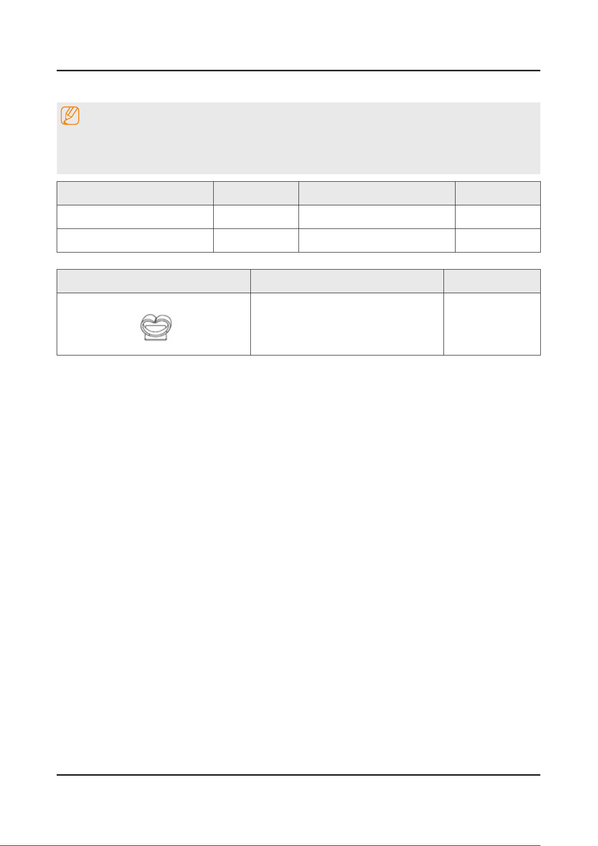
Image Product Code. No
Holder-Wire Stand• BN61-08370A
Page 16

3. Disassembly and Reassemble
3. Disassembly and Reassembly
This section of the service manual describes the disassembly and reassembly procedures for the LED TV.
This LED TV contains electrostatically sensitive devices. Use caution when handling these components.
WARNING
3-1. Disassembly and Reassembly
Disconnect the LED TV from the power source before disassembly.1.
Follow these directions carefully; never use metal instruments to pry apart the cabinet.2.
CAUTION
Place TV face down on cushioned table.
If there is no additional coment, it is same for all inches.3.
Description Picture Description Screws
1
Remove 4 screws from the Stand.
2
Remove Stand.
3
Torque :
7~ 8Kgf.cm
6003-001782
3-1
Page 17

3-2
3. Disassembly and Reassemble
Description Picture Description Screws
Remove 16 screws of Rear-Cover.
4
Remove the Rear-Cover.
5
Torque :
7~ 8Kgf.cm
6003-001782
Torque :
7~ 8Kgf.cm
6003-002755
Remove 8 screws of main board and IP
6
board and Panel.
Remove the connector of main board, IP
7
board, Panel and etc.
Torque :
7~ 8Kgf.cm
001-002756
Page 18

3-3
3. Disassembly and Reassemble
Completed disassembly.
8
Description Picture Description Screws
NOTE
Reassembly procedures are in the reverse order of disassembly procedures.
Page 19

3-4
3. Disassembly and Reassemble
3-2. Disassembly(PTC)
How to disassembly
Description Picture Description Refer
Place TV face up on cushioned table.
1
Remove the function Assy.
2
Disassemble ASSY MISC P-CHASSIS
3
TOP(U/D & L/R)with hooks.
Page 20

3-5
3. Disassembly and Reassemble
Description Picture Description Refer
Disassemble COF lm to the guide with
4
care not to make it bent or folded.
CAUTION
Disassemble COF lm to the guide with
care not to make it bent or folded.
Disassemble ASSY FRAME P-MOLD
5
MIDDLE (L/R) & ASSY FRAME P-MOLD
MIDDLE (U/D) with hooks.
* HOOK POINT
U : 6 pts. D : 5 pts. R : 4 pts. L : 4 pts.
CAUTION
Check whether the hooks are completely
disassembled.
1
2
2
2
1
2
6
Completed.
Page 21

3-6
3. Disassembly and Reassemble
How to reassembly
Description Picture Description Refer
Place PCT.
1
Assemble ASSY MISC P-CHASSIS
2
TOP(L/R) and ASSY MISC P-CHASSIS
TOP( U/D) using the hook.
* HOOK POINT
Top : 6Point / Bottom : 5 Point
Right : 4-Point / Left : 4-Point
CAUTION
Check whether the hooks are completely
assembled.
Place Assy MISC P-Open Cell on the
3
FRAME-MOLD MIDDLE GUIDE in the
same direction as the picture.
CAUTION
Be careful not to make COF lm bent or
folded during assembly of open cell.
1
2
2
2
1
2
Page 22

3-7
3. Disassembly and Reassemble
Description Picture Description Refer
When Source PCB attach CHASSIS
4
BOTTOM, it should be attach the Gasket.
Assemble ASSY MISC P-CHASSIS
5
TOP(L/R) & ASSY MISC P-CHASSIS
TOP(U/D) with hooks.
* HOOK POINT
Top : 6Point / Bottom : 5 Point
Right : 4-Point / Left : 4-Point
CAUTION
Check whether the hooks are completely
assembled.
Page 23

3-8
3. Disassembly and Reassemble
Description Picture Description Refer
When Source PCB attach CHASSIS
4
BOTTOM, it should be attach the Gasket.
Assemble ASSY MISC P-CHASSIS
5
TOP(L/R) & ASSY MISC P-CHASSIS
TOP(U/D) with hooks.
* HOOK POINT
Top : 6Point / Bottom : 5 Point
Right : 4-Point / Left : 4-Point
CAUTION
Check whether the hooks are completely
assembled.
Page 24

3-9
3. Disassembly and Reassemble
NOTE
Notice for ASSY MISC P-CHASSIS TOP Assembly
Assembly process of mechanical tools (1)
1. To apply countermeasures against breaking defect
1-1. Causes
-During placement of a panel and MF guide, the panel is hung
due to embo interrruption, which provokes the panel to be
broken which T/C assembly.
1-2. Solutions
-To conduct 4 siodes touching inspection by operators.
-To quantify SOP because of operational defects between DS
photoelectricity progress.
Assembly process of mechanical tools (2)
2. To apply countermeasures against TAB IC dent defect
2-1. Causes
-A dent occurs due to T/C & S-IC interrruption which is caused
by T/C assembly on the opposite or the L/R of the S-PCB.
2-2. Solutions
-To x the top chassis by making it leant based on S-PCB.
-To quantify SOP because of operational defects between DS
photoelectricity progress.
Page 25

4. Troubleshooting
4-1. Troubleshooting
4-1-1. Previous Check
Check List for Initial operation
AC Power Cord connected to the TV and the wall receptacle. -
Standby Power/IR Indicator LED is turned On. -
If Power/IR Indicator is not on check 10p power cable is connected and for correct Standby Voltage from SMPS to Main. Also check Jog Function Cable.
Power turned On with Jog Function or Remote. -
Power on command from main Board to SMPS. -
Power/IR Indicator Flashes. -
Panel Back Lights are turned On. -
If no Backlights, unplug AC Power Cord, unplug 10 pin connector to SMPS, plug in AC Power Cord, Back light should come on. Check Main Board operation for error.
Power/IR Indicator goes off. -
Picture or banner is displayed. -
* If nothing is displayed , check the LVDS cable.
4. Troubleshooting
Main Ass'y
10p cable
LVDS Cable
Speaker
CNM803 (to Powr board)
1 A13V_PW 6 PS On/Off
2 UNDER_DRV 7 A13V_PW
3 A13V_PW 8 GND
4 PWM_BLU 9 GND
5 A13V_PW 10 GND
Power Ass'y
CNL802 (SMPS TO PANEL)
1 D+ 6 S2-
2 D+ 7 S3+
3 S1- 8 D-
4 S2+ 9 D-
5 N.C
Inverter Cable
4-1
Page 26

4-2
4. Troubleshooting
4-2. How to Check Fault Symptom
No power & no picture
Diagnostics
Check the LED of function
Yes
Open the BACK-COVER and check the
10P power cable
Yes
Check the A13V of BD207
Yes
Check the Q206 base, voltage must be
no larger than 0.5V
Yes
Check the A5V of L202, B13V of Q202,
B5V of Q207.
Yes
Check the A3.3V/B3.3V of Main IC
Check B1.8V of DDR IC
IC201#1, IC205#3, IC204#5
Yes
No
No
No
No
No
No
Check link of AC voltage
Connect the 10p power cable
Change the SMPS
Change the Main Assy
Change the Main Assy
Change the Main Assy
Check the 13V of LVDS
Q204#1/2/5/6
Yes
Change the LVDS
No
No
Change the PANLE
Page 27

MAIN IC
FLASH
TUNER
IC201
L202
IC205
Q207
IC204
BD207
Q204
Q203
Q202
4-3
4. Troubleshooting
Location of Parts
Main Board_Front
Page 28

4-4
4. Troubleshooting
No Video (HDMI 1, 2 - Digital Signal)
Diagnostics
If the LED of POWER is off,
check Back Light is turn on
Yes
Check the SelfTest.
(Support Self Diagnosis Picture Test)
Remain other Problem
Yes
choose the HDMI SOURCE
Check the HDMI CONNECTOR
Yes
Check a below signal
CN401 CN404
(Pin#12,10 , #1#3, #4#6, #7#9 )(HDMI1)
(HDMI RX_Clk , RX_Data)
Yes
Check a below signal
TP-EVEN_TXCLK+, EVEN_TXCLK-
TP-EVEN_TX*+, EVEN_TX*-
No
No
No
No
No
Check what is status ‘Stand-by’ or not
Check for connecting external device
Input the HDMI signal
Check CN401,CN404
Check the HDMI cable
Change the Main Assy
Check IC1001 (XL1)
Change the Main Assy.
Yes
Check the LVDS
/ Change the LCD panel
Page 29

4-5
4. Troubleshooting
Location of Parts
Main Board_Front
A
Detail
ODD_TX0
ODD_TX1
ODD_TX2
A
#12
#9
#6
#3
EVEN_TX0
EVEN_TX1
EVEN_TX2
EVEN_TXCLK
ODD_TX3
#10
#7
#4
#1
ODD_TXCLK
ODD_TX3
ODD_TX4
ODD_TX4
Page 30

4-6
4. Troubleshooting
No picture (COMPONENT)
Diagnostics
If the LED of POWER is off,
check Back Light is turn on
Yes
Check a video source & cable
Yes
Check the SelfTest.
(Support Self Diagnosis Picture Test)
Remain other Problem
Yes
Check
R426(COMP1_Y/CVBS)
R424(COMP1_PR)
R425(COMP1_PB)
Yes
Check the assembling state of LVDS /
Change the Panel
No
No
No
No
Check what is status ‘Stand-by’ or not
Check Video signal
Check for connecting external device
Check the CN403
Change the Main Assy
Page 31

4-7
4. Troubleshooting
Location of Parts
Main Board_Front
A
B
Detail
R425
R426
A
R424
ODD_TX0
ODD_TX1
ODD_TX2
ODD_TXCLK
ODD_TX3
ODD_TX4
B
EVEN_TX0
EVEN_TX1
EVEN_TX2
EVEN_TXCLK
ODD_TX3
R421
R422
ODD_TX4
Page 32

4-8
4. Troubleshooting
No sound
Diagnostics
Check the source & sound cable.
(Comp/PC/DVI to HDMI)
Yes
Check the SelfTest.
(Support Self Diagnosis Picture Test)
Remain other Problem?
Yes
Check the DC B13V to BD305
Yes
Check the sound data
- L-, L+, R-, R+
Yes
Change the speaker
No
No
No
No
Input a Sound source
Check for connecting external device
Change the Main Assy
Check the IC1001 (XL1) / IC301
(Sound AMP)
Change the Main Assy
Page 33

4-9
4. Troubleshooting
Location of Parts
Main Board_Front
A
B
Detail
A
L- L+ R- R+
B
BD305
Page 34

4-10
4. Troubleshooting
4-3. Factory Mode Adjustments
4-3-1. Detail Factory Option
NOTE
If you replace the main board with new one, please change the factory option as well.
The options you must change are "Type".
UN40H5003AFXZA
Inches 40"
Vendor INX
PANEL
SMPS BOARD
MAIN BOARD
Byte Item
0 Factory Reset -
1 Type 40D6AF0D
2 Basic Model H5003
3 SVC Model 5003
4 Local Set US
5 Tuner ATSC / Clear QAM
6 Ch table NONE
Code BN95-01856A
Spec. V400HJ6-PE1
Vendor DYREL
Code BN44-00769A
Spec. L40HF_EDY
Chassis Ass'y BN91-13503E
PBA Ass'y BN94-07592A
Page 35

4-3-2. Entering Factory Mode
4-11
4. Troubleshooting
To enter ‘Service Mode’ Press the remote -control keys in this sequence :
If you do not have Factory remote control•
Power OFF MENU 1 8 2 Power On
If you have Factory remote control•
INFO Factory
If you don’t have Factory remote control, can’t control some menus. •
Initial SERVICE MODE DISPLAY State
Option
Sub Options
Sound
Debug
SVC
W/B ADJUST
ADC ADJUST
Advanced
Tuner Self Test
DTV TUNER SLEF
Shop Option
On DTV
T-MXL1AUSC-0708.0
Build Date : Apr 8 2014
HDCP SUCCESS
Option
USB Serial Off
40A6AH0S
-
Page 36

4-12
4. Troubleshooting
4-3-3. Factory Data
Note
Version of the software is written in 0002.•
Black• : I should not be possible to adjust or change that does not require a change item
Blue : Adjustment Services for the corresponding
Red : Items that are secured
Option
Factory Menu Name Data Range
Factory Reset -
Type 40D6AF0D
SW Model UH5003
BOM Model 5003
Ch Table NONE
Local Set US
TUNER MXL601
MRT Option
LVDS FORMAT JEIDA
HV Flip Off
China HD Off
NT Conversion On
Num of AV 1
Num of COMP 1
Num of HDMI 2
Num of USB 1
e-Pop Default ON
Num of Headph. 0
Num of Optical 1
Front Color N/A
Debug
Factory Menu Name Data Range
Spread Spectrum
spread spectrum
period
amplitude
DDR spread
Eco Sensor Debug
Page 37

Svc
4-13
4. Troubleshooting
Factory Menu Name Data Range
Test Pattern off
Delete S/N FAIL
W/B ADJUST
Factory Menu Name Data Range
Picture Options dynamic
color tone cool
R-gain 79
G-gain 128
B-gain 150
R-Offset 1024
G-offset 1024
B-offset 1024
sub_contrast 142
sub_brightness 1024
ADC ADJUST
Factory Menu Name Data Range
Mode
R-gain
G-gain
B-gain
R-Offset
G-offset
B-offset
AUTO ADC
--
4626
4522
4626
2048
256
2048
--
Advanced
Factory Menu Name Data Range
PWMMax
WCE
Enhance
EPA Standard
ColorMapping
7.5 IRE NTSC
100
On
Page 38

4-14
4. Troubleshooting
Factory Menu Name Data Range
Gamma
0.93
Tuner Self Test
Factory Menu Name Data Range
H sync Magn.
Burst Freq
IF Level
Bottom level
Peak Level
Synctip noise level
Tuner power level
H sync Magn.TH
IF Level TH
Bottom level TH
Synctip noise TH
Tuner power TH
0x0000
No-BURST
0x0000
0x0000
0x0000
0x0000
0dB
0x0000
0x0072
0x004F
0x0005
-DB60
CVBS Starus
Check Result
Fail
Fail
DTV TUNER SELFTEST
Factory Menu Name Data Range
Lock Status
IF level
Tuner power level
BER(dB)
SNR(dB)
IF level TH
Tuner power TH
BER(dB) TH
SNR(dB) TH
Check Result
No Lock
0x0000
0dB
0
0
0xA300
-90dB
0
16
Fail
Shop Mode
Factory Menu Name Data Range
Shop mode
Off
Page 39

4-4. White Balance
4-15
4. Troubleshooting
4-4-1. Calibration
Into the Factory Mode.1.
Select 2. SVC Menu.
Select 3. ADC/WB menu.
Select 4. ADC menu.
Option
Control
SVC
Expert
ADC/WB
Advanced
4-4-2. Service Adjustment
ADC
AV Calibration
Comp Calibration
HDMI Calibration
You must perform Calibration in the Lattice Pattern before adjusting the White Balance.
Color Calibration
AdjustSpecication•
Source Setting Mode Pattern Use Equipment
HDMI 1280 x 720@60 Hz Pattern #24 (Only Chess Pattern) CA210 & Master MSPG925 Generator
(Chess Pattern)
Use other equipment only after comparing the result with that of the Master equipment. -
Input mode Calibration Pattern
CVBS IN (Model_#1) Perform in NTSC B&W Pattern #24 Lattice
Component IN (Model_#6) Perform in 720p B&W Pattern #24 Lattice
HDMI IN Perform in 720p B&W Pattern #24 Lattice
Page 40

4-16
4. Troubleshooting
Method of Color Calibration (AV)
Apply the NTSC Lattice (N0. 3) pattern signal to the AV IN 1 port.1.
Press the Source key to switch to “AV1” mode.2.
Enter Service mode.3.
Select the “ADC” menu.4.
Select the “AV Calibration” menu.5.
In“AVCalibrationOff”status,pressthe“►”keytoperformCalibration.6.
When Calibration is complete, it returns to the high-level menu.7.
You can see the change of the “AV Calibration” status from Failure to Success. 8.
Method of Color Calibration (Component)
Apply the 720p Lattice (N0. 6) pattern signal to the Component IN 1 port.1.
Press the Source key to switch to “Component1” mode.2.
Enter Service mode.3.
Select the “ADC” menu.4.
Select the “Comp Calibration” menu.5.
In“CompCalibrationOff”status,pressthe“►”keytoperformCalibration.6.
When Calibration is complete, it returns to the high-level menu.7.
You can see the change of the “Comp Calibration” status from Failure to Success.8.
Method of Color Calibration (HDMI)
Apply the 720p Lattice (N0. 6) pattern signal to the HDMI1/DVI IN port.1.
Press the Source key to switch to “HDMI1” mode.2.
Enter Service mode.3.
Select the “ADC” menu.4.
Select the “HDMI Calibration” menu.5.
In“HDMICalibrationOff”status,pressthe“►”keytoperformCalibration.6.
When Calibration is complete, it returns to the high-level menu.7.
You can see the change of the “HDMI Calibration” status from Failure to Success.8.
Page 41

4-4-3. Adjustment
4-17
4. Troubleshooting
Into the Factory Mode.1.
Select 2. SVC Menu.
Select 3. ADC/WB menu.
Select 4. White Balance menu.
Option
Control
SVC
Expert
ADC/WB
Advanced
White Balance
(low light)
Sub Bright
R offset
G offset
B offset
(hight light)
Sub Contrast
R gain
G gain
B gain
Page 42

4-18
4. Troubleshooting
4-5. Software Upgrade
SamsungmayofferupgradesfortheTV’srmwareinthefuture.TheseupgradescanbeperformedviatheTVwhenitis
connectedtotheInternet,orbydownloadingthenewrmwarefromsamsung.comtoaUSBmemorydevice.
Alternative Software (Backup) shows The previous version that will be replaced.•
Software is represented as ‘Year/Month/Day_Version’. The more recent the date, the newer the software version •
Installing the latest version is recommended.
4-5-1. By USB
InsertaUSBdrivecontainingthermwareupgradedownloadedfromsamsung.comintotheTV.PFirmwarefoldermust
be on thre root directory of the USB. Please be careful to not disconnect the power or remove the USB drive while
upgrades are being applied.
"MENU Support Software Update"
4-5-2. By Online
Upgrades the software using the Internet.
First,congureyournetwork.FordetailedproceduresonusingtheNetworkSetting,refertothe‘SettingtheNetwork’•
instructions.
If The internet connection doesn’t operate properly, connection can be broken, please retry downloading. If the •
problem still happens, download by USB and upgrade.
4-5-3. Alternative Software (Backup)
Ifthereisanissuewiththenewrmwareanditisaffectingoperation,youcanchangethesoftwaretotheprevious
If Software was changed, existing Software is displayed.•
you can change current Software to Alternative Software by ‘Alternative Software’.•
Page 43

4-6. Rear Cover Dimension
4-19
4. Troubleshooting
4-6-1. UN40H5003 Cover Rear Dimension
895.9
150.0
144.0
132.4
166.0
347.9
200.0
200.0
31.4
148.5
530.7
273.7
23.1
162.7
Page 44

5. Wiring Diagram
Main Board
Power Board
Speaker
FUNCTION& IR
Speaker
CN201
CN801_FHD
CN802_HD
CN301
CN401
CNL802
PANEL
PANEL
S
p
e
a
k
k
k
k
k
k
e
e
e
e
e
e
r
5-1. Wiring Diagram
5. Wiring Diagram
5-1
Page 45

5-2
5. Wiring Diagram
5-2. Connector
Main Board
9
3
6
4
7
5
8
2
1
1
CN801_FHD
1 NC 16 EVEN_TX3+
2 GND 17 EVEN_TX3-
3 FRC_SDA 18 GND
4 FRC_PWM1 19 EVEN_TXCLK-
5 FRC_SCL 20 EVEN_TXCLK+
6 FRC_PWM3 21 GND
7 FRC_PWM2 22 EVEN_TX2+
8 TCON_SDA 23 EVEN_TX2-
9 PANEL_I2C_EN 24 EVEN_TX1+
10 BT_SYNC 25 EVEN_TX1-
11 UPDATE_CHK 26 EVEN_TX0+
12 TCON_SCL 27 EVEN_TX0-
13 GND 28 GND
14 EVEN_TX4+ 29 ODD_TX4+
15 EVEN_TX4- 30 ODD_TX4-
1
CN801_FHD
31 ODD_TX3+ 42 ODD_TX0-
32 ODD_TX3- 43 GND
33 GND 44 GND
34 ODD_TXCLK+ 45 GND
35 ODD_TXCLK- 46 FRC_PWM4
36 GND 47 PANEL_13V_PW
37 ODD_TX2+ 48 PANEL_13V_PW
38 ODD_TX2- 49 PANEL_13V_PW
39 ODD_TX1+ 50 PANEL_13V_PW
40 ODD_TX1- 51 PANEL_13V_PW
41 ODD_TX0+
Page 46

5-3
5. Wiring Diagram
1
CN802_HD
1 VCC 16 EVENCLK+
2 VCC 17 EVENCLK-
3 VCC 18 GND
4 VCC 19 EVEN2+
5 VCC 20 EVEN2-
6 GND 21 GND
7 GND 22 EVEN1+
8 GND 23 EVEN1-
9 TCON_WP 24 GND
10 LVDS_FORMAT 25 EVEN0+
11 NC 26 EVEN0-
12 GND 27 GND
13 EVEN3+ 28 SDA_PANEL
14 EVEN3- 29 SCL_PANEL
15 GND 30 NC
2
CN201 (to Powr board)
1 GND 6 SW_POWER_OUT
2 GND 7 A13V_PW
3 A13V_PW 8 PWM_DIMMING
4 GND 9 A13V_PW
5 A13V_PW 10 UNDER_DRIVER
3
CN401 (to Function/IR)
1 IR 5 MSDA
2 GND 6 KEY2
3 A3.3V 7 MEY1
4 MSCL 8 LED_STB
4
CN301 (SPEAKER)
1 R+ 3 L+
2 R- 4 L-
6
CN401_H1 (to HDMI1)
1 HDMI1_RX2+ 11 GND
2 GND 12 HDMI1_RXCLK-
3 HDMI1_RX2- 13 CEC
4 HDMI1_RX1+ 14 NC
5 GND 15 HDMI1_SCL_DDC
6 HDMI1_RX1- 16 HDMI1_SDA_DDC
7 HDMI1_RX0+ 17 GND
8 GND 18 HDMI1_5V
9 HDMI1_RX0- 19 HDMI1_HOT_PLUG
10 HDMI1_RXCLK+
7
CN404_H2 (to HDMI2)
1 HDMI2_RX2+ 11 GND
2 GND 12 HDMI2_RXCLK-
3 HDMI2_RX2- 13 CEC
4 HDMI2_RX1+ 14 ARC2_SIGLE
5 GND 15 HDMI2_SCL_DDC
6 HDMI2_RX1- 16 HDMI2_SDA_DDC
7 HDMI2_RX0+ 17 GND
8 GND 18 HDMI2_5V
9 HDMI2_RX0- 19 HDMI2_HOT_PLUG
10 HDMI2_RXCLK+
8
CN705_U1 (USB1)
1 USB_VCC 3 USB_DP
2 USB_DM 4 GND
9
OP301 (OPTICAL)
1 SPDIF_OUT 3 GND
2 GND
5
CN403 (to Component&AV)
1 GND 9 TEST_PR
2 COMP2_Y_CVBS 10 GND
3 INDENT_VIEDO2 11 COMP1_SL_IN
4 GND 12 TEST_SL
5 COMP2_PB 13 GND
6 INDENT_COMP2 14 COMP1_SR_IN
7 GND 15 TEST_SR
8 COMP2_PR
Page 47

5-4
5. Wiring Diagram
5-3. Connector Functions
Connector Function
CN201 CNM803
CN801 T-CON
Supply main power and dimming signal from IP board to Main Board.
The LVDS signal transfered from Main Board to Panel.
Page 48

5-5
5. Wiring Diagram
5-4. Cables
Use LEAD (Main-IP 10P) LVDS CALBE (Main - panel, FHD)
Code No. BN39-01956A BN96-32005M
Image
Use FUNCTION CABLE ( 8P ) FUNCTION
Code No. BN39-01723C BN96-23845A
Image
 Loading...