

Page 1
SUHD TV
Chassis : UWQ61
Model : UE65KS9502T
UE78KS9502T
SERVICE
SUHD TV Contents
1. Precautions
2. Product specications
3. Disassembly and Reassembly
4. Troubleshooting
5. Wiring Diagram
Manual
UE**KS9502T
Page 2

Contents
1. Precautions ...................................................................................................................1-1
1-1. Safety Precautions .............................................................................................................1-1
1-1-1. Warnings ...................................................................................................................1-1
1-1-2. Servicing the LED TV ...............................................................................................1-1
1-1-3. Fire and Shock Hazard .............................................................................................1-1
1-1-4. Product Safety Notices ............................................................................................. 1-2
1-2. Servicing Precautions ..........................................................................................................1-3
1-2-1. General Servicing Precautions ................................................................................. 1-3
1-3. Static Electricity Precautions ...............................................................................................1-4
1-4. Installation Precautions .......................................................................................................1-5
2. Product Specications.................................................................................................2-1
2-1. Product information .............................................................................................................2-1
2-2. Product specication ...........................................................................................................2-2
2-2-1. Specications ...........................................................................................................2-2
2-2-2. Detailed Specications .............................................................................................2-3
2-3. Accessories .........................................................................................................................2-9
2-4. Viewing the Functions .......................................................................................................2-10
2-4-1. 2016'
2-4-2. Picture ....................................................................................................................2-13
2-4-3. Smart Things ..........................................................................................................2-14
2-4-4. Viewing the Panel ...................................................................................................2-15
2-4-5. The Samsung Smart Remote .................................................................................2-18
2-4-6. Using Voice Interaction ........................................................................................... 2-19
2-4-7. Supported Resolutions for UHD Input Signals .......................................................2-20
2-4-8. Supported Formats .................................................................................................2-21
Smart Hub...........................................................................................2-10
3. Disassembly and Reassembly ....................................................................................3-1
3-1. Disassembly and Reassembly ............................................................................................3-1
4. Troubleshooting ...........................................................................................................4-1
4-1. Previous Check ..................................................................................................................4-1
4-2. How to Check Fault Symptom .............................................................................................4-2
4-2-1. Power .......................................................................................................................4-2
4-2-2. Video ....................................................................................................................... 4-11
4-2-3. Audio .......................................................................................................................4-15
4-2-4. Network...................................................................................................................4-16
4-2-5. Smart Hub ..............................................................................................................4-17
4-2-6. Bluetooth / WiFi Module .........................................................................................4-19
4-3. Factory Mode .....................................................................................................................4-20
4-4. Factory Mode Adjustments ................................................................................................4-24
4-4-1. Detail Factory Option ..............................................................................................4-24
4-4-2. Factory Data ...........................................................................................................4-26
4-5. RS-232C ............................................................................................................................4-39
4-6. AV Control Tabe .................................................................................................................4-40
4-7. Updating the TV’s Software ...............................................................................................4-48
Page 3

5. Wiring Diagram .............................................................................................................5-1
5-1. Wiring Diagram ....................................................................................................................5-1
5-2. Connector ............................................................................................................................5-5
5-2-1. Main Board ...............................................................................................................5-5
5-2-2. One Connect Board ..................................................................................................5-8
5-2-3. SMPS Board ...........................................................................................................5-10
5-2-4. LD Board ................................................................................................................5-12
ANNEX. Exploded View & Part List [UE65KS9502TXXH FA01] ......................... ANNEX-1
1-1. Exploded View .......................................................................................................... ANNEX-1
1-1-1. Parts List ........................................................................................................ ANNEX-1
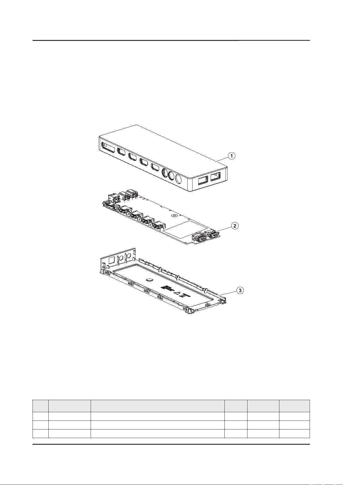
1-2. ONE CONNECT Exploded View .............................................................................. ANNEX-2
1-2-1. Parts List ........................................................................................................ ANNEX-2
2-1. Electrical Parts List ................................................................................................... ANNEX-3
ANNEX. Exploded View & Part List [UE78KS9502TXXH FA01] ......................... ANNEX-1
1-1. Exploded View .......................................................................................................... ANNEX-1
1-1-1. Parts List ........................................................................................................ ANNEX-1
1-2. ONE CONNECT Exploded View .............................................................................. ANNEX-2
1-2-1. Parts List ........................................................................................................ ANNEX-2
2-1. Electrical Parts List ................................................................................................... ANNEX-3
Page 4

This Service Manual is a property of Samsung Electronics Co.,Ltd.
Any unauthorized use of Manual can be punished under applicable
International and/or domestic law.
© 2016 Samsung Electronics Co.,Ltd.
All rights reserved.
Printed in Korea
Page 5
3. Disassembly and Reassemble
3. Disassembly and Reassembly
This section of the service manual describes the disassembly and reassembly procedures for the LED TV.
Disconnect the LED TV from the power source before disassembly.1.
Follow these directions carefully.2.
Use the Samsung Service tool to disassemble the cabinet. -
CAUTION
Recommend to use the Samsung Service tool.•
Recommended Torque for Cabinet/Stand screws : 22.0 ~ 26.5lbf -
A strength of Torque can be changed depending on the situation.•
3-1. Disassembly and Reassembly
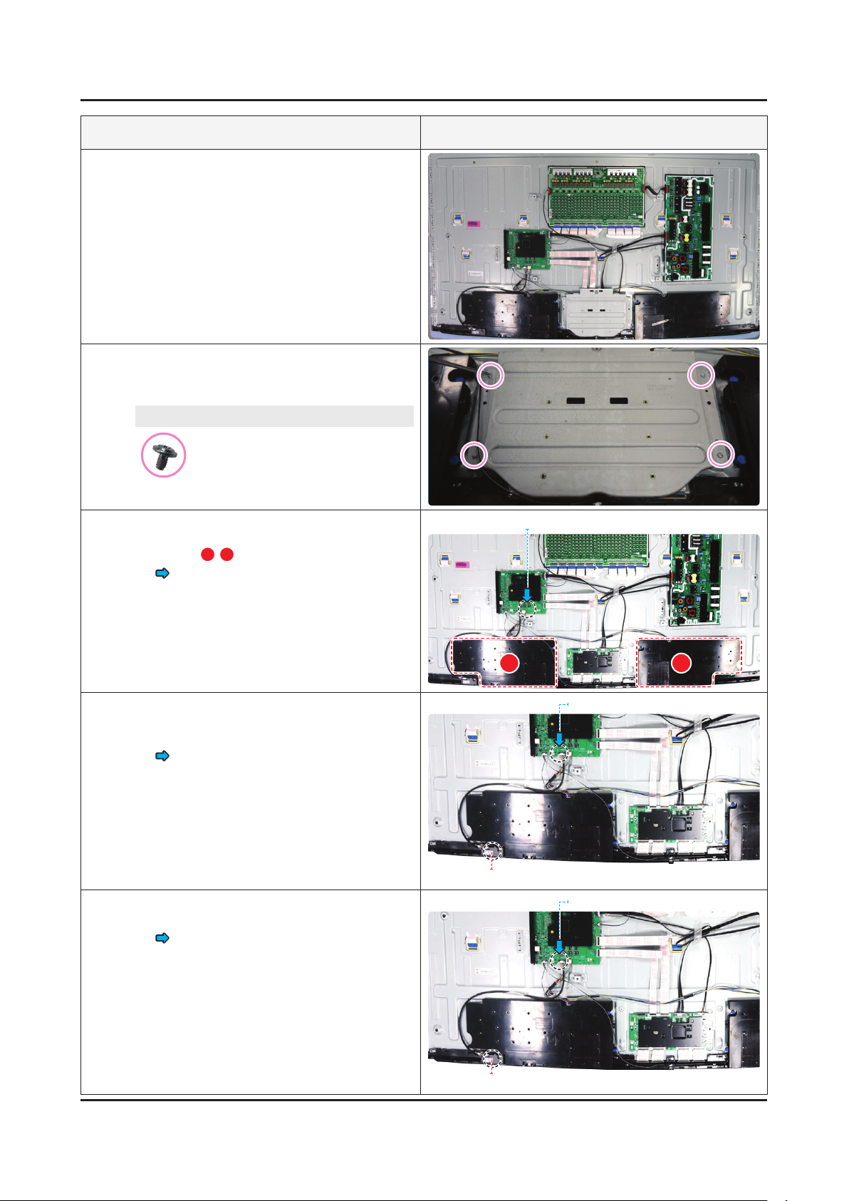
65 inches
Description & Screws Picture Description
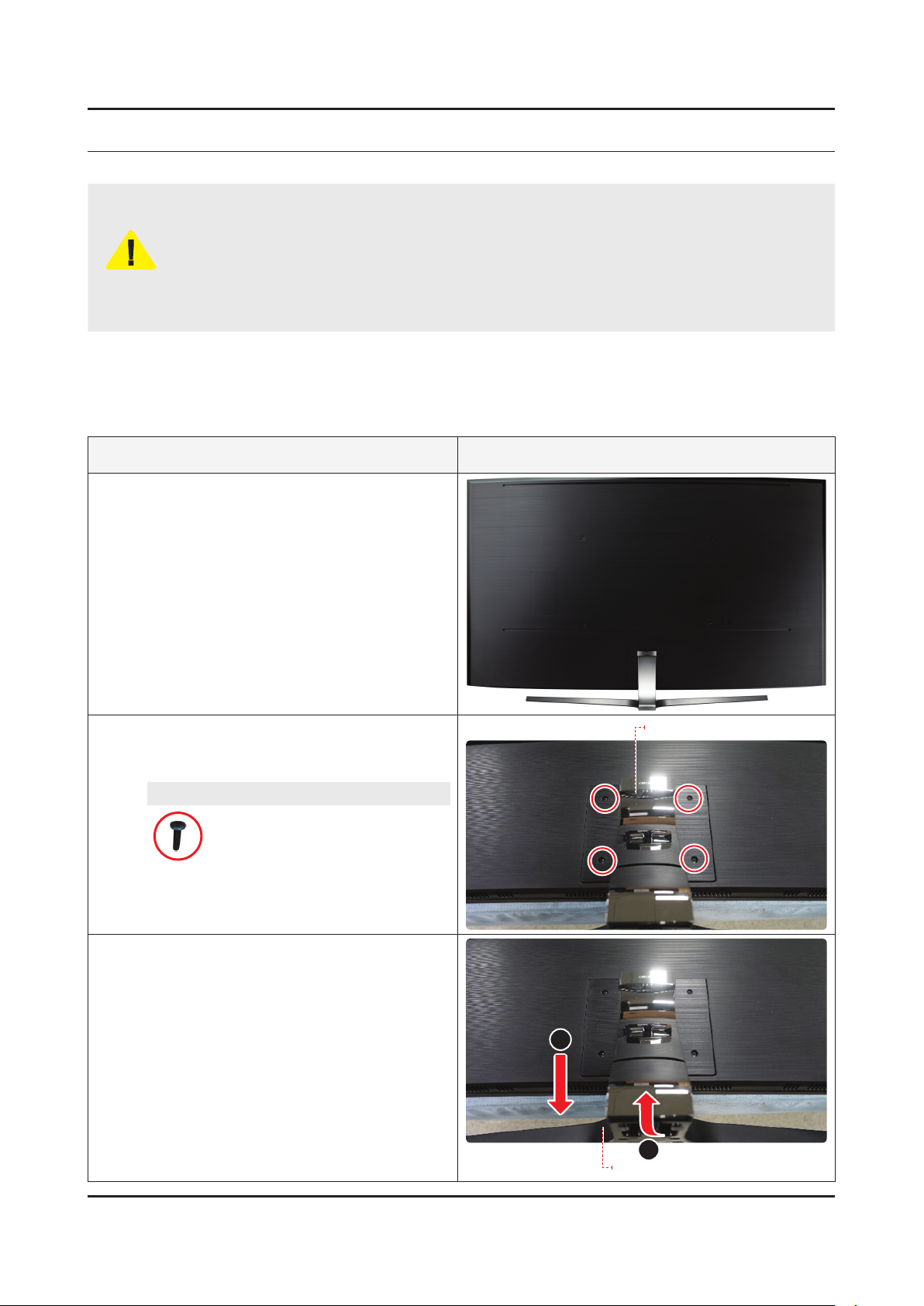
Place the TV on the Curved Cusion.
1
Remove the screws on the ASSY GUIDE
2
P-STAND.
65" : 4 EA•
Screws
6003-001334
SCREW-TAPTYPE : M4 x L14, ZPC(BLK)
Remove the ASSY STAND P-BOTTOM in the
3
order marked as 1~2.
ASSY GUIDE P-STAND
2
1
ASSY STAND P-BOTTOM
3-1
Page 6
3-2
3. Disassembly and Reassemble
Description & Screws Picture Description
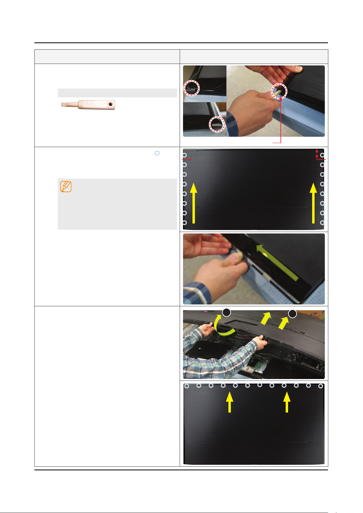
Insert the Samsung Service Jig at the indicated
4
positions (Holes) to release bottom corners of
the ASSY COVER REAR.
SVC JIG-ASSY MISC P-JIG
BN81-12884A
SVC JIG-ASSY MISC P-JIG (Holes)
Release the Hooks at each point (Side: 16
5
points) indicated by Yellow Circles along side
line of the rear cover using the Service tool as a
lever.
NOTE
Not to make Clips (molds of the upper side
locked up on the Bottom Chassis) damaged,
use the service tool only from the bottom
corner to the point (indicated as the Red lines)
apart from the upper side by about 7cm.
Gently lift up the Rear Cover from the bottom
6
side and then push it toward the upper direction
of TV as the below photo to release all mounting
clips located along the upper side of the Rear
Cover as indicated by Yellow Circles.
7cm
1
2
Page 7
3-3
3. Disassembly and Reassemble
Description & Screws Picture Description
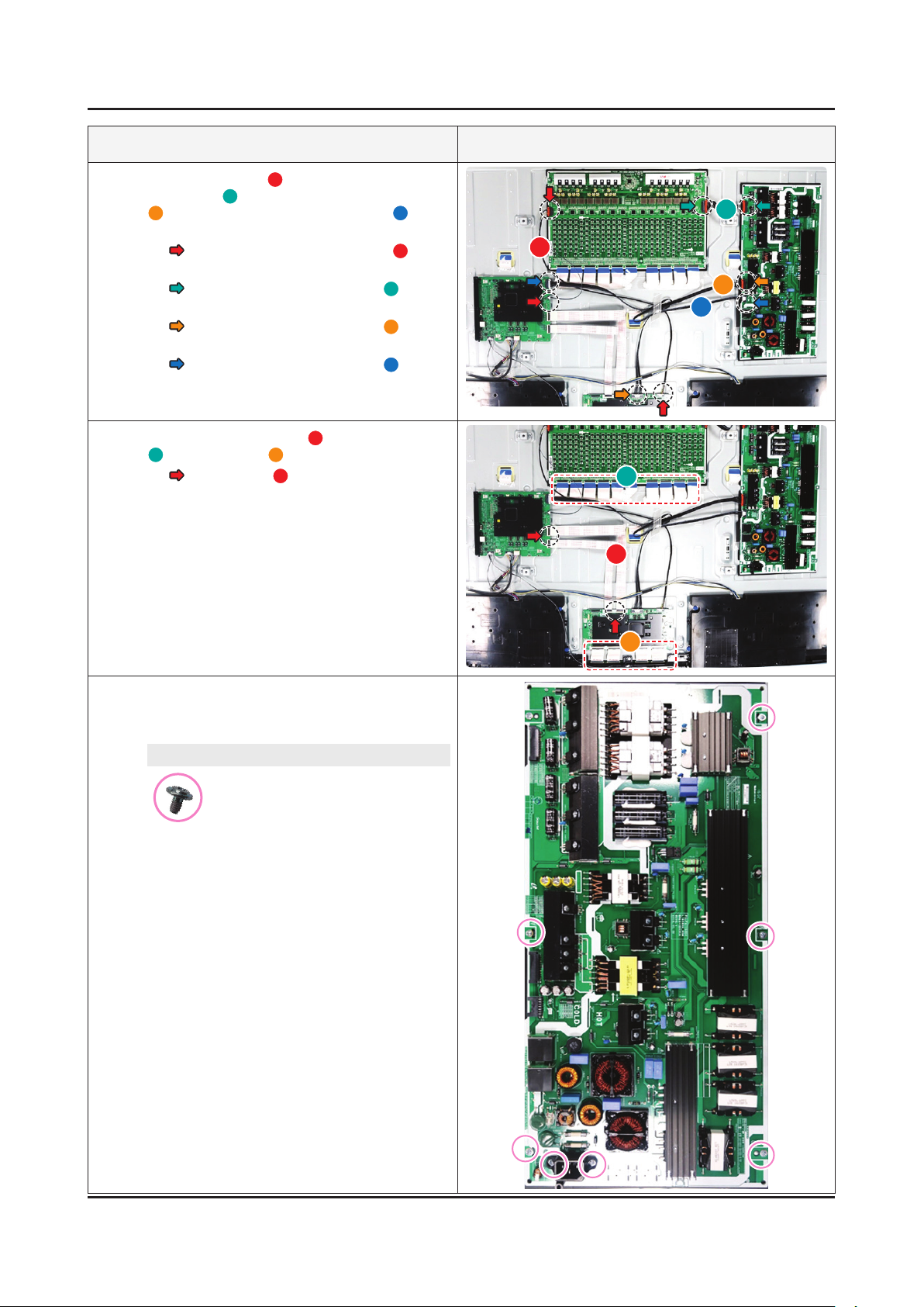
Remove the screws on the Bracket (ASSY
7
BRACKET P-STAND LINK), and then remove it.
65" : 4 EA•
Screws
6001-003016
SCREW-MACHINE : M3 x L5, ZPC(WHT)
8
9
10
Remov the ASSY SPEAKER P-FRONT Cable
and remove the ASSY SPEAKER P-FRONT(
/B).
• ASSY SPEAKER P-FRONT Cable
Remov the ASSY BOARD P-IR FUNCTION
TACT Cable and remove the ASSY BOARD P-IR
FUNCTION TACT.
• ASSY BOARD P-IR FUNCTION TACT
Cable
Remov the NETWORK Cable and remove the
NETWORK-WLAN CLIENT.
• NETWORK Cable
A
ASSY SPEAKER P-FRONT Cable
A B
ASSY BOARD P-IR FUNCTION TACT Cable
ASSY BOARD P-IR FUNCTION TACT
NETWORK Cable
NETWORK-WLAN CLIENT
Page 8
3-4
3. Disassembly and Reassemble
Description & Screws Picture Description
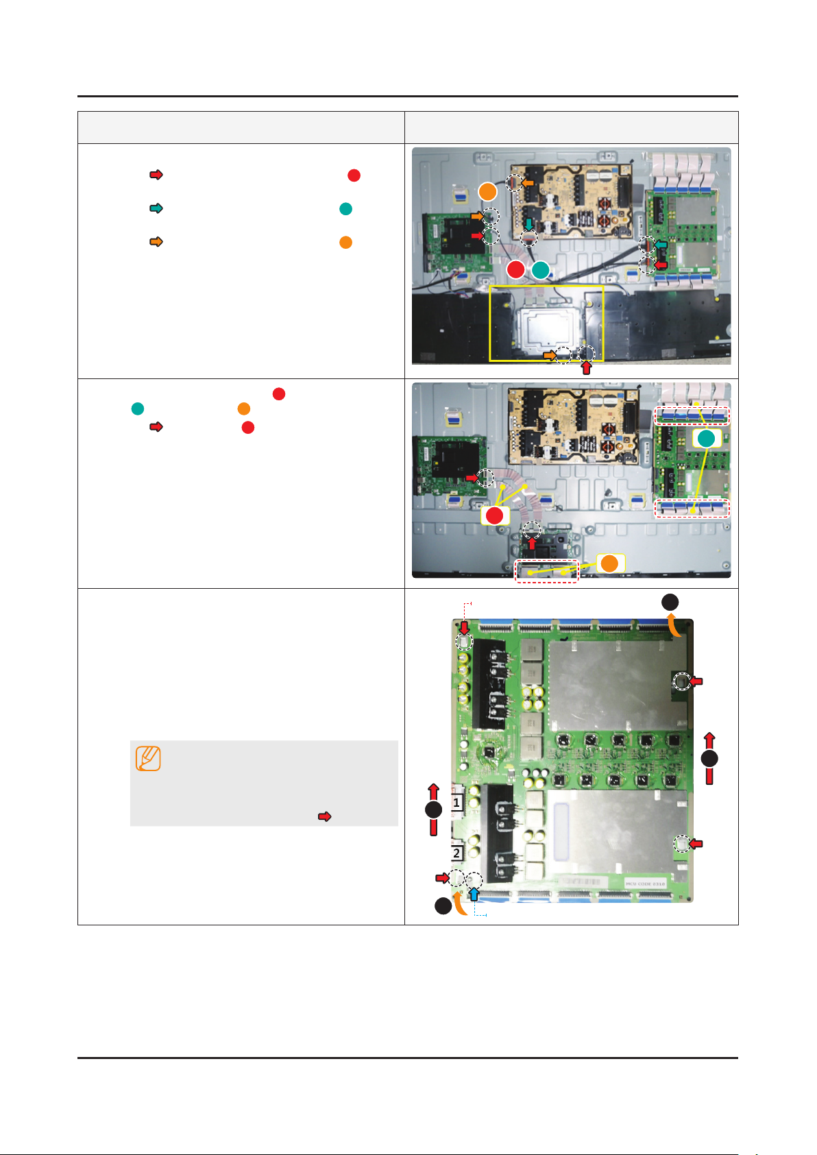
11
12
Remove the Cables.
• LEAD CONNECTOR-DIMMING(A)
(LD - MAIN - FT)
• LEAD CONNECTOR-POWER(B)
(SMPS - LD)
• LEAD CONNECTOR-POWER(C)
(SMPS - MAIN)
Remove the FFC CABLE A(Main-T-CON VX1),
B
(BLU/Dimming), C(Open Cell USIT).
• FFC CABLE(A)
(Main - T-CON)
C
A
B
B
A
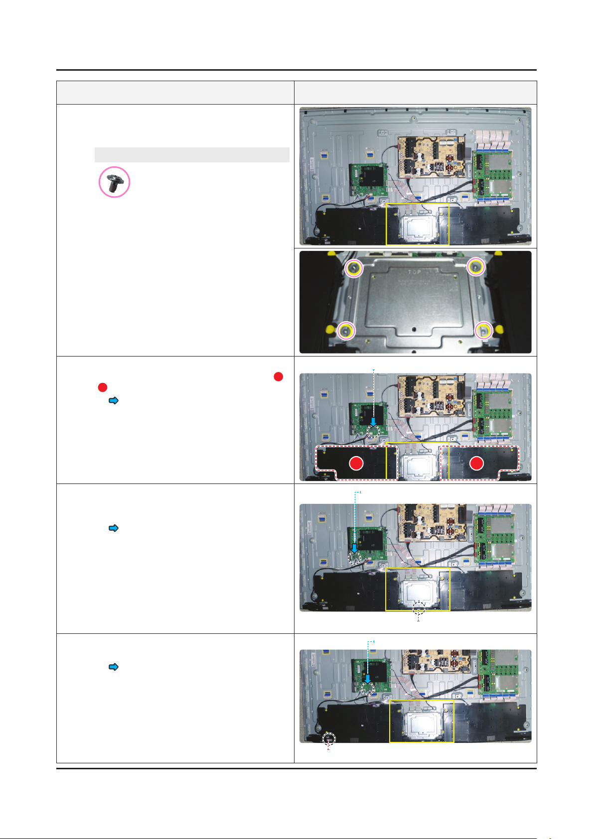
13
Remove the ASSY SMPS P-PD BOARD (LD
Board).
Gently lift out 4 corners of the board to •
release its locks.
Use both hands to hold the board and slide it •
toward the upper side to remove. (It's easier
foryoutousebothhands-amiddlenger
for upper side and a thumb for bottom side
to lift and slide out simultaneously)
NOTE
When installing the ASSY SMPS P-PD
BOARD(LD Board), verify the board is properly
positioned in all 4 mounting slots(
).
C
BottomchassisGuidethexingHoles
2
1
Locking
1
2
Page 9
3-5
3. Disassembly and Reassemble
Description & Screws Picture Description
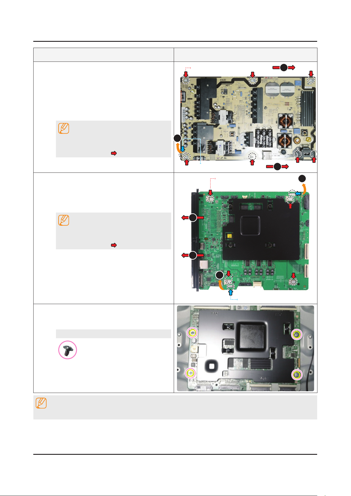
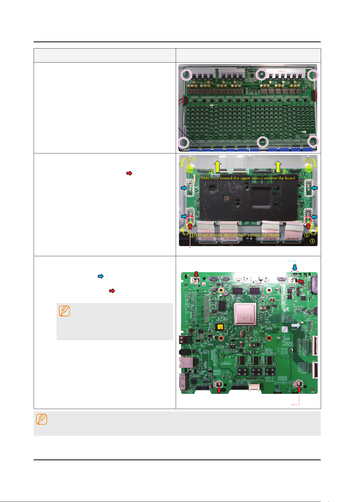
14
15
Remove the DC VSS-PD BOARD (SMPS).
Gently lift out 4 corners of the board to •
release its locks.
Use both hands to hold the board and slide •
it toward the right side to remove. (It's easier
foryoutousebothhands-amiddlenger
for left side and a thumb for bottom side to lift
and slide out simultaneously).
NOTE
When installing the DC VSS-PD BOARD
(SMPS), verify the board is properly positioned
in all 7 mounting slots(
Remove the ASSY PCB MAIN.
Gently lift the top right corner of the board out •
to release the lock.
Use both hands to hold the board and slide to •
the left to release it.
NOTE
When installing the DC VSS-PD BOARD
(SMPS), verify the board is properly positioned
in all 4 mounting slots(
).
).
BottomchassisGuidethexingHoles
1
Locking
BottomchassisGuidethexingHoles
2
2
2
1
2
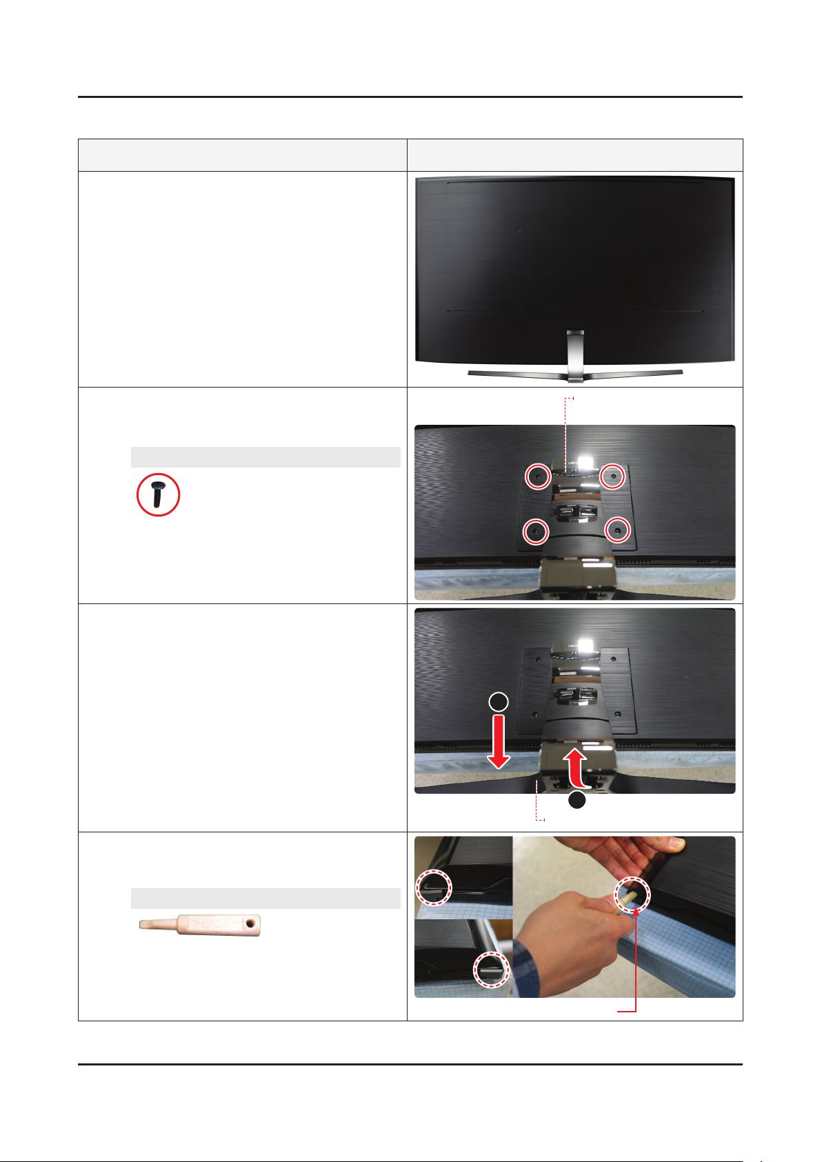
16
Reassembly procedures are in the reverse order of disassembly procedures.
Remove the screws on T-CON BOARD and then
remove the T-CON BOARD.
65" : 4 EA•
Screws
6001-003016
SCREW-MACHINE : M3 x L5, ZPC(WHT)
NOTE
1
Locking
Page 10
3-6
3. Disassembly and Reassemble
78 inches
Description & Screws Picture Description
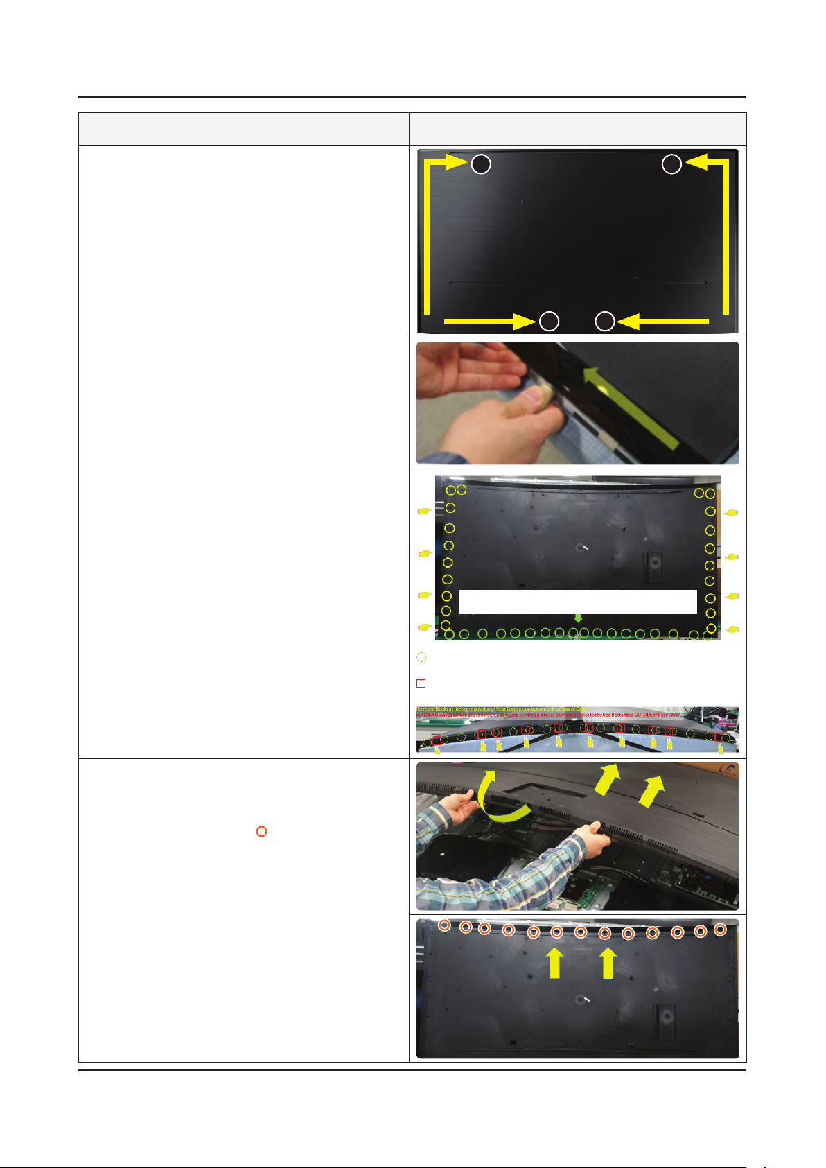
Place the TV on the Curved Cusion.
1
Remove the screws on the ASSY GUIDE
2
P-STAND.
78" : 4 EA•
Screws
6003-001334
SCREW-TAPTYPE : M4 x L14, ZPC(BLK)
Remove the ASSY STAND P-BOTTOM in the
3
order marked as 1~2.
ASSY GUIDE P-STAND
2
Insert the Samsung Service Jig at the indicated
4
positions (Holes) to release bottom corners of
the ASSY COVER REAR.
SVC JIG-ASSY MISC P-JIG
BN81-12884A
1
ASSY STAND P-BOTTOM
SVC JIG-ASSY MISC P-JIG (Holes)
Page 11
3-7
3. Disassembly and Reassemble
Description & Screws Picture Description
Release the Hooks from the clamping wires at
5
each point indicated by Yellow Circles along
side and bottom line of the rear cover (Top Left
& Light : 2 points / Side:18 points / Bottom:18
points) in the order marked as 1~2 using the
Service tool as a lever.
1
2 2
1
Gently lift up the Rear Cover from the bottom
6
side and then push it toward the upper direction
of TV as the side photo to release all mounting
clips located along the upper side of the Rear
Cover as indicated by (Yellow Circles).
There are 18EA Grooves at intervals of about 10cm INSIDE of
Rear Cover along bottom side of rear cover.
: There are Hooks at the same position of Rear Cover along bottom side
of Source Cover.
: 10EA Grooves (which you can insert a samsung service jig into) at
each point indicated by Red Rectangles OUTSIDE of Rear Cover.
Page 12
3-8
3. Disassembly and Reassemble
Description & Screws Picture Description
Remove the screws on the Bracket (ASSY
7
BRACKET P-STAND LINK), and then remove it.
78" : 4 EA•
Screws
6001-003016
SCREW-MACHINE : M3 x L5, ZPC(WHT)
8
9
10
After removing the ASSY SPEAKER P-FRONT
Cable and remove the ASSY SPEAKER
P-FRONT (A/B).
• ASSY SPEAKER P-FRONT Cable
After removing the ASSY BOARD P-IR
FUNCTION TACT Cable and remove the ASSY
BOARD P-IR FUNCTION TACT.
• ASSY BOARD P-IR FUNCTION TACT
Cable
After removing the NETWORK Cable and
remove the NETWORK-WLAN CLIENT.
• NETWORK Cable
ASSY SPEAKER P-FRONT Cable
A B
NETWORK Cable
NETWORK-WLAN CLIENT
NETWORK Cable
NETWORK-WLAN CLIENT
Page 13
3-9
3. Disassembly and Reassemble
Description & Screws Picture Description
11
12
Remove the Cable A(LEAD CONNECTORDIMMING), B(LEAD CONNECTOR-POWER),
C
(LEAD CONNECTOR-POWER) and D(LEAD
CONNECTOR-POWER).
• LEAD CONNECTOR-DIMMING(A)
(LD - MAIN - FT)
• LEAD CONNECTOR-POWER(B)
(SMPS - LD)
• LEAD CONNECTOR-POWER(C)
(SMPS - MAIN)
• LEAD CONNECTOR-POWER(D)
(SMPS - TCON)
Remove the FFC CABLE A(Main-T-Con VX1),
B
(BLU/Dimming), C(Open Cell).
• FFC CABLE(A)
(Main - FT)
B
A
C
D
B
A
13
C
After removing the screws and remove the DC
VSS-PD BOARD(SMPS BOARD).
78" : 7 EA•
Screws
6001-003016
SCREW-MACHINE : M3 x L5, ZPC(WHT)
Page 14
3. Disassembly and Reassemble
Description & Screws Picture Description
14
15
Remove the Screws on LD(Local Dimming)
Board, and then remove the board. (FFC Cable
was already removed)
78" : 6 EA•
Remove T-Con Board.
Gently lift out 4 corners of the board to •
release its locks (Locking
Use both hands to hold the board and slide it •
toward the upper side to remove. (It's easier
foryoutousebothhands-amiddlenger
for upper side and a thumb for bottom side
to lift and slide out simultaneously.)
).
16
Removing ASSY PCB MAIN BOARD.
Gently lift up (Top Right corner) to release the •
lock (Locking
Use both hands to hold (Bottom chassis •
Guide Fixing Hole
the left to release the board.
NOTE
When installing the ASSY PCB MAIN BOARD,
verify the board is properly positioned in all 4
mounting slots.
NOTE
).
) the board and slide to
Locking
Locking
Bottom chassis Guide Fixing Hole
Reassembly procedures are in the reverse order of disassembly procedures.
3-10
Page 15
ANNEX. Exploded View & Part List
ANNEX. Exploded View & Part List [UE78KS9502TXXH FA01]
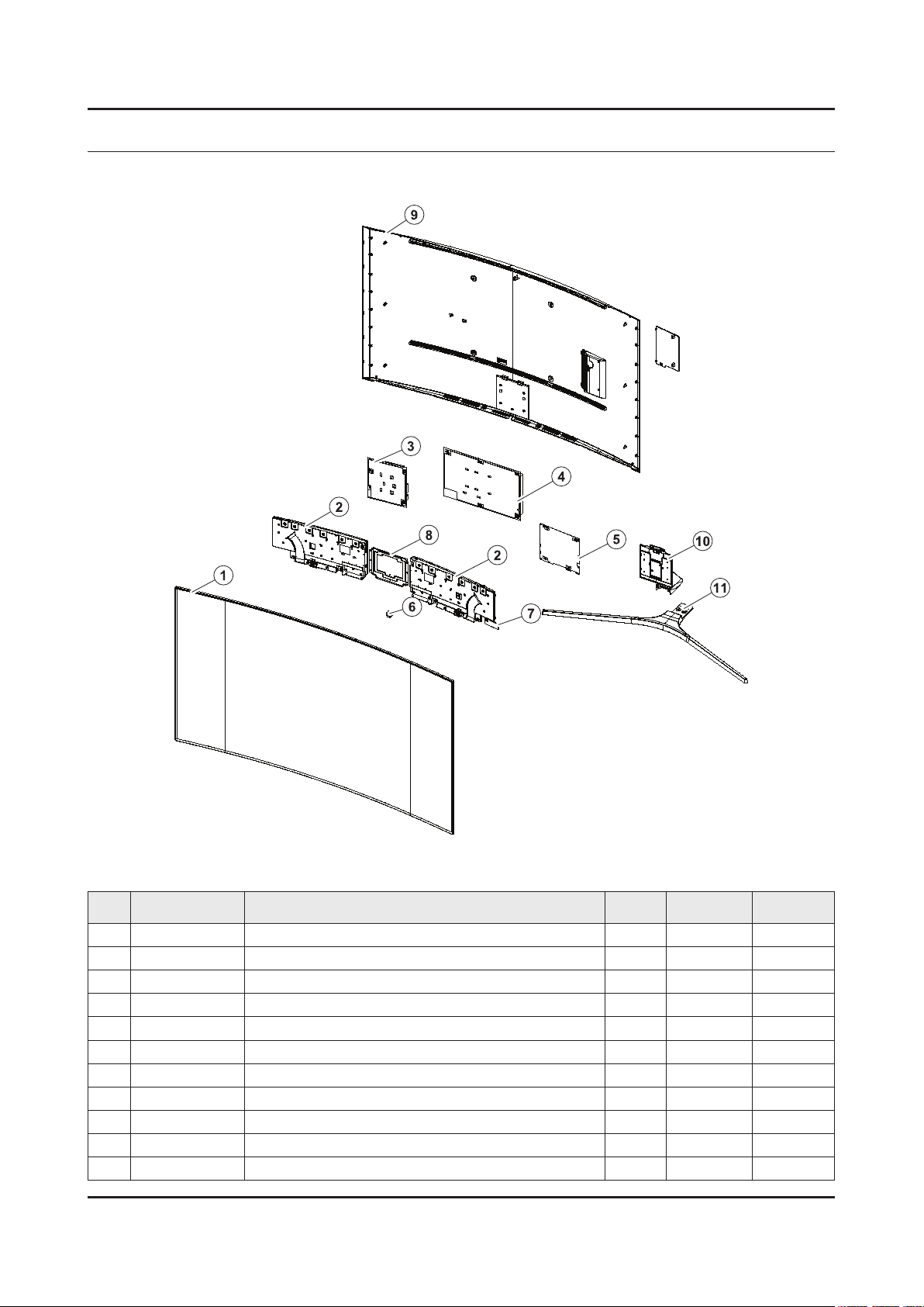
1-1. Exploded View
1-1-1. Parts List
No. Code No. Description & Specication Q’ty SA/SNA Remark
1 BN95-02728B PRODUCT LCD-SDC; CY-YK078FLLV2V/H,KS9800, 1 SA
2 BN96-40264B ASSY SPEAKER P-FRONT; TV-SPK,KS9800,6ohm, 1 SA
3 BN44-00891A DC VSS-PD BOARD; L78S9NA_KSM,AC/DC,415W,1 1 SA
4 BN96-39400A ASSY SMPS P-PD BOARD; L78S9NC_KHSV,L78S9N 1 SA
5 BN94-10846J ASSY PCB MAIN; UK9Y 1 SA
6 BN96-39802E ASSY BOARD P-IR FUNCTION TACT; KS9800,SJ1 1 SA
7 BN59-01239A NETWORK-WLAN CLIENT; WCK730B,USB 2.0,16P, 1 SA
8 BN96-40088E ASSY COVER P-REAR; 78KS9800,PC+ABS+ED20%, 1 SA
9 BN96-40190C ASSY GUIDE P-STAND; 78KS9800,EUROPE,ALDC, 1 SA
10 BN96-40196B ASSY STAND P-BOTTOM; 78KS9800,PC+ABS,SILV 1 SA
ANNEX-1
Page 16
ANNEX-2
ANNEX. Exploded View & Part List
1-2. ONE CONNECT Exploded View
1-2-1. Parts List
No. Code No. Description & Specication Q’ty SA/SNA Remark
1 BN96-40188F ASSY COVER P-TOP; 55KS9000,PC+ABS,V-0,BK0 1 SNA
2 BN94-10924F ASSY PCB MISC-ONE CONNECT MINI; Y16 OCM P 1 SNA
3 BN63-15074E COVER-BOTTOM; OCM PLUS,PC+ABS,MOLD,V-0,BK 1 SNA
Page 17

ANNEX-3
ANNEX. Exploded View & Part List
2-1. Electrical Parts List
Service Bom (SA: SERVICE AVAILABLE, SNA: SERVICE NOT AVAILABLE)
Level Location No. Code No. Description & Specication Q’ty SA/SNA Remark
UE78KS9502TXXH (FA01)
1 R001A BN90-08137E ASSY COVER REAR;UK9Y,78" 1 SNA
0.2 R001A BN96-40088E ASSY COVER P-REAR;78KS9800,PC+ABS+ED20%, 1 SA
..3 BN61-13303A HOLDER-COVER;55KS8000,Si,MOLD,BK0008,HB 2 SNA
..3 CCM1 BN63-02183H SHEET-PROTECTION COVER;Rhcm,PE,T0.05,W13 2 SNA
..3 R001 BN63-14987A COVER-REAR;PC+ABS+ED20%,MOLD,V-1,BK0007, 1 SNA
..3 BN63-15817A SHEET-PROTECTION COVER;78KS9800,PO,T0.06 1 SNA
..3 BN63-15818A SHEET-PROTECTION COVER;78KS9800,PO,T0.06 1 SNA
..3 BN63-15819A SHEET-PROTECTION COVER;78KS9800,PO,T0.06 1 SNA
..3 BN63-15820A SHEET-PROTECTION COVER;78KS9800,PO,T0.06 1 SNA
..3 BN64-03528D INLAY-TERMINAL SIDE;55KS7000,PET,T0.125, 1 SNA
..3 BN68-07835C LABEL-WARNING;40K5500,PET,T0.125,W74,L44 1 SNA
1 S001A BN90-08161B ASSY STAND;UK9Y,78" 1 SNA
0.2 SCREW 6003-001334 SCREW-TAPTYPE;BH,+,S,M4,L14,ZPC(BLK),SWR 4 SA
0.2 S001A BN96-40393B ASSY STAND P-SET;78KS9800,PC+ABS,SILVER 1 SNA
..3 SCREW 6003-001208 SCREW-TAPTYPE;BH,+,S,M4,L12,ZPC(BLK),SWR 5 SA
..3 SG01A BN96-40190C ASSY GUIDE P-STAND;78KS9800,EUROPE,ALDC, 1 SA
...4 SCREW 6001-002997 SCREW-MACHINE;FH,+,M3,L4.0,ZPC(WHT),SWRC 1 SA
...4 SCREW 6003-000282 SCREW-TAPTYPE;BH,+,-,B,M3,L8,ZPC(BLK),SW 2 SA
...4 6902-002059 BAG PE;HDPE/PE FOAM,T0.015/T0.5,W300,L40 1 SNA
...4 SG01 BN61-11376A GUIDE-STAND NECK;78JS9500,ALDC,MOLD,PRES 1 SNA
...4 AH089 BN61-11707H HOLDER-CABLE;78KS9800,ABS,MOLD,BK0007,HB 1 SNA
...4 BN63-07556H SHEET-PROTECTION COVER;TOC,PO,T0.068,W75 1 SNA
...4 BN63-13167B COVER-STAND NECK;78KS9800,PC+ABS+GF15%,M 1 SNA
...4 BN63-13170F COVER-STAND NECK FRONT;78KS9800,ABS,MOLD 1 SNA
...4 BN63-13173F COVER-STAND NECK REAR;78KS9800,PC+ABS,MO 1 SNA
..3 SB02A BN96-40196B ASSY STAND P-BOTTOM;78KS9800,PC+ABS,SILV 1 SA
...4 SCREW 6003-001086 SCREW-TAPTYPE;BH,+,-,B,M3,L12,ZPC(BLK),S 6 SA
...4 6902-002461 BAG PE;HDPE/PE FOAM,T0.015/T0.5,W100,L60 2 SNA
...4 6902-002469 BAG PE;HDPE/PE FOAM,T0.015/T0.5,W160,L30 1 SNA
...4 BN60-00162E SPACER-FOAM;PE FOAM,L50M,GRAY,T0.5,W20 1 SNA
...4 BN61-06538A TAPE-DOUBLE FACE;ACRYL,T0.64,W10,WHITE,T 0 SNA
...4 HOLDER-BOLT BN61-09494D HOLDER-BOLT;KU6500,SWRCH18A,BLK,PRESS,B 8 SA
...4 BN61-12861A BRACKET-STAND RIGHT;Al,NATURAL 1 SNA
...4 BN61-12865A BRACKET-STAND LEFT;Al,NATURAL 1 SNA
...4 BN63-11118E SHEET-PROTECTION COVER;STANDARD ENCLOSUR 1 SNA
...4 RF01 BN67-00398L FOOT-RUBBER;UH6K,Si,GRAY,W8,L15.5,T2 4 SNA
...4 RF01 BN67-00538A FOOT-RUBBER;LED_J4000,Si,GRAY,W8,L15.5,T 4 SNA
...4 BN68-05603A LABEL-E PASS;ART PAPER 90G,W/W 1 SNA
...4 BN95-02919B ASSY COVER STAND SMT-TOP;78",KS9800,SILV 1 SNA
....5 0204-006861 COATING;SMT-L100,CLEAR,0.928,Paint 0 SNA
....5 BN01-00160A TARGET-CHROMIUM CY;Chromium,99.95%,1800x 0 SNA
....5 BN01-00336A TARGET-ALUMINIUM CY;Al,99.9%,1724mm,132d 0 SNA
....5 BN63-14664A COVER-STAND TOP;78JS9100,PC+ABS,MOLD,V-1 1 SNA
Page 18

ANNEX-4
ANNEX. Exploded View & Part List
Level Location No. Code No. Description & Specication Q’ty SA/SNA Remark
....5 BN68-03682A LABEL ETC;Label,W20,L10 1 SNA
1 BN90-08294G ASSY W/I;UKS* 1 SNA
0.2 BN81-08159Z A/S PART SET-ELEC W/I;LED TV ELEC spec-C 1 SNA
0.2 BN81-12851Z A/S PART SET-MECH W/I;UKS9800Y,U78KY* 1 SNA
1 BN91-17401C ASSY SHIELD;UK9Y,78" 1 SNA
0.2 SCREW 6001-002789 SCREW-MACHINE;BH,+,M4,L6,ZPC(WHT),SWRCH1 1 SA
0.2 SCREW 6001-003081 SCREW-MACHINE;PWH,+,M3,L5,ZPC(WHT),SWRCH 11 SA
0.2 BN39-02207C LEAD CONNECTOR-POWER;78KS9800,UL21016,20 1 SA
0.2 BN39-02211D LEAD CONNECTOR-SUB ASSY;78KS9800,UL21451 1 SA
0.2 BN39-02220E LEAD CONNECTOR-SUB ASSY;78KS9800,UL21016 1 SA
0.2 BN39-02233B LEAD CONNECTOR-POWER;78KS9800,UL21016,22 1 SA
0.2 BN39-02240A LEAD CONNECTOR-DIMMING;78KS9800,UL21451, 1 SA
0.2 BN39-02241A LEAD CONNECTOR-POWER;78KS9800,UL21016,16 1 SA
0.2 BN44-00891A DC VSS-PD BOARD;L78S9NA_KSM,AC/DC,415W,1 1 SA
0.2 WIFI BN59-01239A NETWORK-WLAN CLIENT;WCK730B,USB 2.0,16P, 1 SA
0.2 BN62-00367A PAD GAP-THERMAL;F6400,SILICON,T6.5,L35,H 1 SNA
0.2 SB05A BN96-36395C ASSY BRACKET P-STAND LINK;78KS9800,HGI-S 1 SNA
..3 CB18 BN61-11425A BRACKET-STAND LINK;HGI-SGHC,T2,NATURAL 1 SNA
...4 BN61-09605A STUD-PEM;LED TV F6100,SUM24L,L8,PRESS 6 SNA
..3 BN63-04077A GASKET-EMI;PS63P71FHX,CONDUCTIVE FABRIC, 2 SNA
0.2 BN96-39802E ASSY BOARD P-IR FUNCTION TACT;KS9800,SJ1 1 SA
0.2 BN96-40209E FFC CABLE;55K6200,Wrinkle,L500,51P 1 SA
0.2 BN96-40264B ASSY SPEAKER P-FRONT;TV-SPK,KS9800,6ohm, 1 SA
0.2 BN96-40394A FFC CABLE;78KS9800,Wrinkle,L400,41P,16Y 1 SA
1 M0017 BN91-17407J ASSY CHASSIS;UK9Y 1 SNA
0.2 M0014 BN94-10846J ASSY PCB MAIN;UK9Y 1 SA
..3 T0073 AA63-01141D GASKET-EMI;42D5,Conductive Fabric,T1.5,W 1 SNA
..3 BN62-00185A HEAT SINK-ES;PDP42D450,A6063,W14,L18,BLA 1 SNA
..3 BN62-00816A HEAT SINK-PS;55KS9000,A1050,T6.3,W145,L1 1 SNA
..3 BN63-15050D COVER-TERMINAL SIDE;55KS9000,HIPS,MOLD,H 1 SA
..3 BN97-10674D ASSY SMD;UKS9800 1 SNA
...4 0406-001628 DIODE-TVS;AOZ8804ADI,6V,1MAV,5A,TP 1 SA
...4 0504-000126 TR-DIGITAL;KSR1101,NPN,200mW,4.7K/4.7K,S 2 SA
...4 0505-002598 FET-SILICON;AP2317GN,P,20V,-4.2A,0.052oh 1 SA
...4 0505-002893 FET-SILICON;AO4801AS,P,30V,-5A,2W,SOIC-8 1 SA
...4 0505-003264 FET-SILICON;AO4447AL,P,30V,-17A,7mohm,3. 1 SA
...4 0505-003397 FET-SILICON;2N7002K,N,60V,0.38A,1.19ohm, 1 SA
...4 0801-003603 IC-CMOS LOGIC;MC74LCX244MN2TWG,Octal buf 1 SA
...4 1001-001998 IC-ANALOG MULTIPLEX;NX3DV221GM,USB switc 1 SA
...4 1006-001576 IC-DRIVER/RECEIVER;MAX3221ECPWR,TSSOP,16 1 SA
...4 1103-001564 IC-EEPROM;S-24C512CI-J800,512Kbit,64Kx8, 1 SA
...4 1105-002704 IC-DDR4 SDRAM;K4F8E304HB-MGCH,LPDDR4-SDR 3 SA
...4 1201-004003 IC-AUDIO AMP;TAS880021,TSSOP,48P,12.5x6. 3 SA
...4 1203-004364 IC-VOL. DETECTOR;RT9818C-42PV,SOT-23,3P, 1 SA
...4 1203-008105 IC-POSI.FIXED REG.;S-13A1D33-E800,HSOP,8 1 SNA
...4 1203-008391 IC-DC/DC CONVERTER;AOZ1269QI-02,QFN-23L, 1 SA
...4 1203-008392 IC-VOL. DETECTOR;S-6414AAB-L800X,TSOT-23 1 SA
Page 19

ANNEX-5
ANNEX. Exploded View & Part List
Level Location No. Code No. Description & Specication Q’ty SA/SNA Remark
...4 1203-008732 IC-DC/DC CONVERTER;SYD104ADC,TSOT-23,6,3 1 SA
...4 1203-008733 IC-DC/DC CONVERTER;AOZ1236QI-02,QFN,23,4 1 SA
...4 1203-008735 IC-DC/DC CONVERTER;AOZ1267QI-02,QFN,23,4 1 SA
...4 1204-003679 IC-DECODER;SDP1501,FCPBGAH,1230P,35*35mm 1 SA
...4 1205-004822 IC-SWITCH;TPS22965DSGR,SON,8P,2x2x0.75mm 3 SNA
...4 1205-005519 IC-SWITCH;ET20163,SOT23-5,5P,2.95x3.02mm 4 SA
...4 1205-005554 IC-REPEATER;TMDS181,VQFN,48P,7x7mm,PLAST 1 SA
...4 IS01 1209-002183 IC-SENSOR;S-5851AAA-M6T1U,SOT,6Z30,2.9x1 1 SA
...4 1405-001271 VARISTOR;35V,20VDC,5A,1.0x0.5mm,TP,100V, 11 SA
...4 2007-000039 R-CHIP;0ohm,1%,1/10W,TP,1608 8 SA
...4 2007-000146 R-CHIP;6.8Kohm,5%,1/16W,TP,1005 1 SNA
...4 2007-000932 R-CHIP;470ohm,5%,1/16W,TP,1005 1 SNA
...4 2007-001292 R-CHIP;33ohm,5%,1/16W,TP,1005 12 SNA
...4 2007-001298 R-CHIP;51ohm,5%,1/16W,TP,1005 1 SNA
...4 2007-007108 R-CHIP;43.2Kohm,1%,1/16W,TP,1005 2 SA
...4 2007-007313 R-CHIP;6.8Kohm,1%,1/16W,TP,1005 4 SA
...4 2007-007316 R-CHIP;3.3Kohm,1%,1/16W,TP,1005 3 SNA
...4 2007-007334 R-CHIP;200Kohm,1%,1/16W,TP,1005 4 SNA
...4 2007-007520 R-CHIP;20ohm,1%,1/10W,TP,1608 12 SA
...4 2007-007627 R-CHIP;16Kohm,1%,1/16W,TP,1005 1 SA
...4 2007-007798 R-CHIP;10ohm,1%,1/16W,TP,1005 1 SA
...4 2007-008067 R-CHIP;21Kohm,1%,1/10W,TP,1608 2 SA
...4 2007-008136 R-CHIP;36Kohm,1%,1/16W,TP,1005 1 SA
...4 2007-008269 R-CHIP;51Kohm,1%,1/16W,TP,1005 1 SA
...4 2007-008298 R-CHIP;49.9ohm,1%,1/16W,TP,1005 17 SA
...4 2007-008391 R-CHIP;6.34Kohm,1%,1/16W,TP,1005 1 SA
...4 2011-001261 R-NETWORK;33ohm,5%,1/16W,L,CHIP,8P,TP,2. 6 SA
...4 2011-001344 R-NETWORK;100ohm,5%,1/16W,L,CHIP,8P,TP,2 6 SA
...4 AD480 2203-000233 C-CER,CHIP;0.1nF,5%,50V,C0G,TP,1005 12 SA
...4 AD480 2203-000254 C-CER,CHIP;10nF,10%,16V,X7R,TP,1005 1 SA
...4 AD480 2203-000278 C-CER,CHIP;0.01nF,0.5pF,50V,C0G,TP,1005 1 SA
...4 AD480 2203-000386 C-CER,CHIP;0.015nF,5%,50V,C0G,TP,1005 3 SA
...4 AD480 2203-000714 C-CER,CHIP;3.3nF,10%,50V,X7R,TP,1005 12 SA
...4 AD480 2203-005054 C-CER,CHIP;0.0047nF,0.25pF,50V,NP0,TP,10 2 SA
...4 AD480 2203-006048 C-CER,CHIP;100nF,10%,10V,X7R,TP,1005 1 SA
...4 AD480 2203-006377 C-CER,CHIP;4700nF,10%,25V,X5R,TP,2012 3 SNA
...4 AD480 2203-006844 C-CER,CHIP;470nF,10%,10V,X5R,TP,1005 3 SA
...4 AD480 2203-007269 C-CER,CHIP;22000nF,20%,10V,X5R,TP,2012(2 30 SA
...4 2409-001338 C-POLYMER ,CHIP;47uF,20%,6.3V,TP,3.2x1.6 1 SA
...4 2703-004724 INDUCTOR-SMD;8.2uH,20%,4T,0.072Ohm,2300m 12 SA
...4 2801-004021 CRYSTAL-SMD;24.576MHz,20ppm,28-AAN,12pF, 1 SA
...4 3301-001364 BEAD-SMD;1000ohm,1608,TP,1085ohm/108MHz, 7 SNA
...4 3709-001782 CONNECTOR-CARD SLOT;68P,1.27mm,ANGLE,AU, 1 SA
...4 3711-007741 CONNECTOR-HEADER;BOX,14P,2R,2.0mm,ANGLE, 1 SA
...4 EH01 3711-007803 HEADER-BOARD TO CABLE;BOX,12P,1R,1.25mm, 1 SA
...4 EH01 3711-007838 HEADER-BOARD TO CABLE;BOX,6P,1R,1.25mm,S 1 SA
...4 3711-009106 CONNECTOR-HEADER;BOX,20P,2R,2mm,ANGLE,SN 1 SA
Page 20

ANNEX-6
ANNEX. Exploded View & Part List
Level Location No. Code No. Description & Specication Q’ty SA/SNA Remark
...4 3722-003199 JACK-MODULAR;8P/8C,Y,ANGLE,NONE,AU,1PORT 1 SA
...4 3722-003394 JACK-PHONE;1P/6C,AU,BLK,ANGLE,3.6PI,9x14 1 SA
...4 6302-001376 GASKET-SMD;,,CONDUCTIVE FABRIC,T14,W43,L 6 SNA
...4 BN41-02505A PCB-MAIN;KS9700/KS9800,FR-4,4L,1.2T,214x 1 SNA
...4 CB07 BN61-13312B BRACKET-PCB;55KS8000,SK5,T0.3,13.7,11.4, 8 SNA
...4 BN97-10856B ASSY MICOM-SUB;JMMICOM_EU_TV,UWQ60,W25Q4 1 SNA
....5 1107-002226 IC-NOR FLASH;W25Q40CLSSIP,4Mbit,SOIC,8P, 1 SA
...4 BN97-10858A ASSY MICOM-MAIN;T-JZMDEUC,UWQ60,KLM8G1GE 1 SNA
....5 1107-002362 IC-EMMC;KLM8G1GEND-B031,8GB,64Gb MLC x 1 1 SNA
..3 BN97-10873A ASSY DRM;Jazz M,DVB,NagSam, MAC, HDCP, C 1 SNA
...4 BN46-00109H KEY CODE-CERTIFICATION;MAC,TV/AV,General 1 SNA
...4 BN46-00110P KEY CODE-CERTIFICATION;MIRACAST(HDCP2.2) 1 SNA
...4 BN46-00496A KEY CODE-CERTIFICATION;Jazz-M,Nagra CSC 1 SNA
...4 BN46-00514A KEY CODE-CERTIFICATION;CI PLUS,Jazz M, J 1 SNA
..3 M0131 MD63-00103A GASKET-TAPE;GRANDSLAM,Conductive Fabric, 1 SNA
1 BN91-17868A ASSY FIXING-JACKPACK;Y16 OCM 1 SA
0.2 AA68-02626A LABEL-PQS;ART,W40,L12,SERIAL 2 SNA
0.2 BN39-02210A ONECONNECTMINI CABLE;KS7000~KS9000,44P,L 1 SA
0.2 RB01 BN63-15074E COVER-BOTTOM;OCM PLUS,PC+ABS,MOLD,V-0,BK 1 SNA
..3 0103-005041 RESIN PC ABS;FR3200TV,901408,BK0008,1.2m 100 SNA
0.2 BN69-13267A BOX ACCESSORY;CB,SW-E,L373,W308 1 SNA
0.2 OCMBD BN94-10924F ASSY PCB MISC-ONE CONNECT MINI;Y16 OCM P 1 SNA
..3 AH62-00243A HEAT SINK-ES;HT-E3500,A6063,W23,L23,BLAC 1 SA
..3 OCM BD BN97-10869F ASSY SMD;7/8/9 SERIES 1 SNA
...4 DS01A 0401-001056 DIODE-SWITCHING;MMBD4148SE,100V,200mA,SO 2 SA
...4 DR01A 0402-001614 DIODE-RECTIFIER;S1G,400V,1A,DO-214AC,TP 2 SA
...4 0403-001783 DIODE-ZENER;BZB84-C6V2,5.8~6.6V,300mW,SO 4 SNA
...4 0404-001404 DIODE-SCHOTTKY;BAT721C,40V,200mA,SOT-23, 4 SA
...4 0404-001881 DIODE-SCHOTTKY;SS3040-HE,40V,3000mA,SOD- 3 SA
...4 0406-001200 DIODE-TVS;RClamp0504F,6V,1MAV,TP 3 SA
...4 0406-001290 DIODE-TVS;3.0SMCJ20A,22.2V,24.5V,5MAV,30 2 SNA
...4 0406-001317 DIODE-TVS;SMAJ14A,15.6V,17.2V,1MAV,6.5VP 2 SNA
...4 0406-001635 DIODE-TVS;SMF5.0A,6.4V,6.7V,7V,200MAV,20 5 SA
...4 0501-000002 TR-SMALL SIGNAL;KSA812,PNP,150mW,SOT-23, 1 SNA
...4 0501-000445 TR-SMALL SIGNAL;KTC3875S-Y,NPN,150mW,SOT 18 SC
...4 0801-003292 IC-CMOS LOGIC;7WB66,Bus Switch,MAB08A,8P 1 SA
...4 0801-003598 IC-CMOS LOGIC;TC7SZ00FU,2-Input NAND Gat 1 SA
...4 0801-003604 IC-CMOS LOGIC;NL17SZ17DFT2G,SC-70,5P,TP, 1 SA
...4 1103-001583 IC-EEPROM;BR24T02FJ-WGE2,2Kbit,256x8,SOP 4 SNA
...4 1203-007697 IC-DC/DC CONVERTER;LNBH26SPQR,QFN,24,4x4 1 SA
...4 1203-008102 IC-POSI.FIXED REG.;S-13A1D12-E800,HSOP,8 2 SNA
...4 1203-008104 IC-POSI.FIXED REG.;S-13A1D18-E800,HSOP,8 1 SNA
...4 1203-008345 IC-POSI.ADJUST REG.;S-13A1ADJ-E800X,HSOP 1 SA
...4 1204-003677 IC-DECODER;SDP1503,FCPBGAH,396P,18*18mm, 1 SA
...4 1205-005537 IC-REPEATER;TCA9517,VSSOP,8P,3.00x3.00mm 1 SA
...4 2007-000879 R-CHIP;4.7ohm,1%,1/10W,TP,1608 1 SA
...4 2007-000999 R-CHIP;510ohm,1%,1/10W,TP,1608 1 SA
Page 21

ANNEX-7
ANNEX. Exploded View & Part List
Level Location No. Code No. Description & Specication Q’ty SA/SNA Remark
...4 2007-002900 R-CHIP;11Kohm,1%,1/10W,TP,1608 1 SNA
...4 2007-007139 R-CHIP;47Kohm,1%,1/16W,TP,1005,T0.35 10 SA
...4 2007-007309 R-CHIP;12Kohm,1%,1/16W,TP,1005,T0.35 1 SA
...4 2007-007312 R-CHIP;20Kohm,1%,1/16W,TP,1005 12 SA
...4 2007-007488 R-CHIP;75Kohm,1%,1/16W,TP,1005 7 SNA
...4 2007-007587 R-CHIP;3.6Kohm,1%,1/16W,TP,1005 2 SNA
...4 2007-007766 R-CHIP;2Kohm,1%,1/16W,TP,1005 27 SNA
...4 2007-007767 R-CHIP;200ohm,1%,1/16W,TP,1005 10 SA
...4 2007-007868 R-CHIP;90.9ohm,1%,1/10W,TP,1608 2 SA
...4 2007-007942 R-CHIP;1Mohm,1%,1/16W,TP,1005 2 SNA
...4 2007-007992 R-CHIP;1ohm,1%,1/10W,TP,1608 1 SA
...4 2007-008015 R-CHIP;75ohm,1%,1/16W,TP,1005 1 SNA
...4 2007-008134 R-CHIP;12.4Kohm,1%,1/16W,TP,1005 5 SC
...4 2007-008167 R-CHIP;120Kohm,1%,1/16W,TP,1005 1 SC
...4 2007-008263 R-CHIP;3Kohm,1%,1/16W,TP,1005 3 SA
...4 2007-008294 R-CHIP;33ohm,1%,1/16W,TP,1005 6 SA
...4 2011-001449 R-NETWORK;22ohm,5%,1/16W,L,4P,TP,1.0x1.0 4 SA
...4 AD480 2203-000359 C-CER,CHIP;0.15nF,5%,50V,C0G,TP,1005,0.5 3 SNA
...4 AD480 2203-000425 C-CER,CHIP;0.018nF,5%,50V,C0G,TP,1005 2 SA
...4 AD480 2203-000585 C-CER,CHIP;0.22nF,10%,50V,X7R,TP,1005 1 SA
...4 AD480 2203-000812 C-CER,CHIP;0.033nF,5%,50V,C0G,TP,1005 6 SA
...4 AD480 2203-000940 C-CER,CHIP;0.47nF,10%,50V,X7R,TP,1005 1 SA
...4 AD480 2203-002285 C-CER,CHIP;10nF,10%,50V,X7R,TP,1005 5 SNA
...4 AD480 2203-005083 C-CER,CHIP;220nF,10%,50V,X7R,TP,1608,0.8 4 SA
...4 AD480 2203-006562 C-CER,CHIP;1000nF,10%,10V,X5R,TP,1005 40 SNA
...4 AD480 2203-006824 C-CER,CHIP;4700nF,10%,10V,X5R,TP,1608 3 SNA
...4 2703-000213 INDUCTOR-SMD;470nH,10%,1.35Ohm,35mA,15,M 1 SA
...4 2703-001938 INDUCTOR-SMD;56nH,5%,1005,1.5Ohm,200mA,1 7 SA
...4 2703-004868 INDUCTOR-SMD;6.8uH,20%,4.0T,0.043Ohm,250 2 SA
...4 2703-005191 INDUCTOR-SMD;1.5uH,20%,6060,T4.5,0.02Ohm 2 SA
...4 2703-005194 INDUCTOR-SMD;3.3uH,20%,4.5,0.03Ohm,4500m 2 SA
...4 2801-005372 CRYSTAL-SMD;24.576MHz,20ppm,HCX-3SB,12 p 1 SA
...4 3701-001967 CONNECTOR-HDMI;19P,A,FEMALE,AU,0.5mm,BLK 4 SA
...4 3707-001104 CONNECTOR-OPTICAL;ANGLE,SPDIF 1 SA
...4 3710-004144 CONNECTOR-SOCKET;44P,1R,0.5mm,SMD-A,AU,B 2 SA
...4 3722-003457 JACK-USB;4P/1C,NI,BLK,ANGLE,A,2.0,13.1x1 3 SA
...4 BN40-00324A TUNER-DTV AIR CABLE SAT;DNTT243H6A,DNTT2 1 SA
...4 BN41-02510A PCB-OCM;KS8000/KS9000,FR-4,4L,1.2T,199x6 1 SNA
0.2 T001A BN96-40188F ASSY COVER P-TOP;55KS9000,PC+ABS,V-0,BK0 1 SNA
..3 6902-001408 BAG PE;HDPE/PE FOAM,T0.015/T0.5,W120,L25 1 SNA
..3 M0131 BN63-00558A GASKET-EMI;GG15AS,Conductive Fabric,T3,W 1 SNA
..3 BN63-07272J SHEET-PROTECTION COVER;OCM+,PE,W205,L100 0 SNA
..3 T001 BN63-15073F COVER-TOP;OCM PLUS,PC+ABS,MOLD,V-0,BLACK 1 SNA
...4 0103-005041 RESIN PC ABS;FR3200TV,901408,BK0008,1.2m 100 SNA
1 BN92-20057A ASSY P/MATERIAL;UK9Y,78" 1 SNA
0.2 6902-001584 BAG PE;HDPE/PE FOAM,T0.015/T0.5,W2000,L1 1 SNA
0.2 6902-001797 PACKING SHEET;HDPE/PE FOAM,T0.015/1.0,W1 1 SNA
Page 22

ANNEX-8
ANNEX. Exploded View & Part List
Level Location No. Code No. Description & Specication Q’ty SA/SNA Remark
0.2 6902-002233 BAG AIR;LDPE,-,T0.2,W900,L1850,TRP,-,-,- 1 SNA
0.2 6922-000003 BAND;PP,T0.8,W18,L1650M,TRP,DA69-90145A 9 SNA
0.2 T0214 AA61-20285C HOLDER-BOX;ALL,PP,MOLD,BLACK,HB,HB,17.5g 4 SNA
0.2 BN02-00102B TAPE-FILAMENT;FILAMENT,#8917,T0.15,W25,L 1 SNA
0.2 BN02-00319B TAPE-OPP;OPP,T0.05,W75,L800M,CLEAR,ROLL 2 SNA
0.2 BN68-02422B LABEL WARNING;ALL,ART PAPER,T0.05,W240,L 1 SNA
0.2 BN69-03982N PACKING ANGLE;ALL,PAPER,-,-,-,-,-,-,- 2 SNA
0.2 BN69-05418M WRAP;T0.017,500,2000000,2000000,500 0 SNA
0.2 BN69-06640A PAD-DP SHEET;PAD,CB,SW4,,W1120,L950,,,,, 2 SNA
0.2 BN69-06640E PAD-PACKING;TRUCK PAD,CB,-,,W410,L2500,, 1 SNA
0.2 BN69-13396A CUSHION-SET;78KS9800,EPS,16.7g/l,WHT 1 SNA
0.2 BN69-13398A CUSHION-SET SIDE;78KS9800,EPS,16.7g/l,WH 2 SNA
..3 0103-005099 RESIN EPS;BASF303,Natural,Natural 4000 SNA
0.2 BN69-13942R PALLET-WOODEN;78" KS9500,WOOD,-,W960,L19 1 SNA
1 BN92-20069E ASSY BOX;UK9Y,78" 1 SNA
0.2 BH68-00662A LABEL BOX;ALL,ART PAPER,W60,L110,WHT,NO 1 SNA
0.2 BN68-05640A LABEL BOX;ALL,ART PAPER,W110,L130,EUROPE 1 SNA
0.2 BN69-13728D BOX UNIT-OUT;78KS9800,CB,DW4,C3,L1890,W4 1 SNA
0.2 BN69-13748A BOX UNIT-IN;78KS9800,CB,DW1,C1,L2342,W79 1 SNA
1 BN92-20074J ASSY LABEL;UK9Y 1 SNA
0.2 0203-001598 TAPE-FILAMENT;FILAMENT,#8915,T0.15,W12,L 0 SNA
0.2 BN68-06708G LABEL-RATING;Monitor,WW,PP,T0.161,W93,L7 1 SNA
0.2 BN68-07519A LABEL-ENERGY;ALL JORDAN,WW,PP,T0.135,W60 1 SNA
0.2 BN68-07877G LEAFLET-QUICK SETUP GUIDE;KS9800 78/88", 1 SNA
1 ACCE1 BN92-20086Q ASSY ACCESSORY;UK9Y 1 SNA
0.2 ACCE2 BN96-39431C ASSY ACCESSORY-CABLE;UK9Y 1 SNA
..3 T0268 3903-000864 CBF-POWER CORD;DT,EU/KOR,LP-33,250V,10A, 1 SA
..3 4301-000101 BATTERY-ALKALINE;1.5V,1650mAH,LR6,14.5x5 2 SNA
..3 6902-001962 BAG PE;LDPE,BIOBASED,T0.05,W400,L300,TRP 1 SNA
..3 BN59-01242A REMOCON-SMART CONTROL;2016 TV,Samsung,14 1 SA
..3 M9889 BN63-01798B CLOTH-CLEAN;CLOTH,SEA BLUE,ToC 1 SA
..3 EH03A BN96-36071C ASSY HOLDER P-RING;LED,JS9K,ABS,BLACK,HB 1 SNA
...4 6902-002497 BAG ZIPPER;LDPE,T0.05,W100,L250,TRP,RECY 1 SNA
...4 AH365 BN61-10572A HOLDER-WALL RING;HU9000 78",ABS,MOLD,BLA 4 SA
....5 0103-004609 RESIN ABS;HF-0680U,K21294,BK0007,HB,High 48 SNA
0.2 ACCE4 BN96-39432Q ASSY ACCESSORY-MANUAL;UK9Y 1 SNA
..3 6902-001964 BAG PE;LDPE,BIOBASED,T0.03,W200,L300,TRP 1 SNA
..3 T0527 BN68-00513A LABEL-E PASS;ALL MODEL,WW,YUPO,W50,L15,W 2 SNA
..3 BN68-03548J LEAFLET-WARRANTY;comm,Samsung,17Lang,Mid 1 SNA
..3 BN68-04972E LEAFLET-REGULATORY GUIDE;ALL,SAMSUNG,W/W 1 SNA
..3 BN68-07598A LEAFLET-FICHE;ALL,W/P,0 1 SNA
..3 BN68-07860E MANUAL USERS;KS9800,XH,W/P,EURO B5 1 SNA
..3 BN68-08099A LEAFLET;JAZZ-M,EUROPE,W/P,W176,L250,4COL 1 SNA
0.2 FC05A BN96-40567A ASSY COVER P-TERMINAL;78KS9800,PC+ABS+ED 1 SA
..3 6902-000294 BAG PE;LDPE,T0.05,W160,L250,TRP,Hole Y,B 1 SNA
..3 BN63-15664A COVER-TERMINAL;78KS9800,PC+ABS+ED20%,MOL 1 SNA
1 BN95-02728B PRODUCT LCD-SDC;CY-YK078FLLV2V/H,KS9800, 1 SA
Page 23

ANNEX-9
ANNEX. Exploded View & Part List
Level Location No. Code No. Description & Specication Q’ty SA/SNA Remark
0.2 SCREW 6001-003075 SCREW-MACHINE;BH,+,M3,L4,ZPC(WHT),SWRCH1 12 SA
0.2 6001-003168 SCREW-MACHINE;CH,+,M3,L5,ZPC(BLK),SWRCH1 10 SNA
0.2 BN60-01460A SPACER-FOAM;78KS9800,PU FOAM,L50M,BLACK, 2 SNA
0.2 BN68-05722A LABEL-E PASS;POLYPROPYLENE,NON-COATING 1 SNA
0.2 BN90-08246A ASSY MISC-BLU;Y16,LCM 1 SNA
..3 SCREW 6001-003075 SCREW-MACHINE;BH,+,M3,L4,ZPC(WHT),SWRCH1 24 SA
..3 BN02-00508B TAPE PET;49KS7000,PET,T0.05,W10,L45,BLAC 5 SNA
..3 BN61-13676A FRAME-CHASSIS REAR LEFT;78KS9800,PC+GF10 1 SNA
..3 BN61-13859A FRAME-CHASSIS REAR RIGHT;78KS9800,PC+GF1 1 SNA
..3 BN61-13867A DIFFUSER PLATE;16Y_KS9800_78INCH_DIFFUSE 1 SNA
..3 BN61-13868A OPTICAL SHEET-HIGH COLOR;16Y_KS9800_78IN 1 SNA
..3 BN61-13869A OPTICAL SHEET-COMPLEX;16Y_KS9800_78INCH_ 1 SNA
..3 BN61-13870A OPTICAL SHEET-DBEF;16Y_KS9800_78NCH_DBEF 1 SNA
..3 BN96-40059A ASSY LED BAR P;78inch_SDC_C,CEM3 6 SNA
..3 BN96-40060A ASSY LED BAR P;78inch_SDC_B,CEM3 2 SNA
..3 BN96-40061A ASSY LED BAR P;78inch_SDC_A,CEM3 2 SNA
..3 BN96-40229A ASSY CHASSIS REAR P;78KS9800,STS 1 SNA
...4 SCREW 6001-002759 SCREW-MACHINE;CH,+,M3,L4,ZPC(BLK),SWRCH1 7 SA
...4 SCREW 6001-003016 SCREW-MACHINE;PWH,+,M3,L5.0,ZPC(WHT),SWR 8 SA
...4 M0909 AA63-01387A GASKET-EMI;SP-P300M,Conductive Fabric,T2 6 SNA
...4 T0139 AA65-30007A HOLDER-WIRE;PA66,PA66,MOLD,GRAY,V-0 2 SNA
...4 BN02-00102B TAPE-FILAMENT;FILAMENT,#8917,T0.15,W25,L 13 SNA
...4 BN02-00485A TAPE PET;KS7000,PET,T0.05,W7,L50,BLACK 6 SNA
...4 BN60-01460A SPACER-FOAM;78KS9800,PU FOAM,L50M,BLACK, 2 SNA
...4 CB20 BN61-08936C BRACKET-WALL;HGI-SGHC,T2,BLACK,BLACK ED- 4 SNA
...4 BN61-11378A SUPPORT-PLATE;JS9500 78,PC,V-2,WHITE,W92 26 SNA
...4 BN61-11765A SUPPORT-PLATE;JS9500 78,PC,V-2,WHITE,W92 8 SNA
...4 BN61-12801A HOLDER-SOURCE PCB;JS9500,ABS,MOLD,GRAY,H 8 SNA
...4 BN61-13557A BRACKET-WIRE;55KS7000,SW-C,T1,60,SILVER 4 SA
...4 BN61-13557E BRACKET-WIRE;49KS7000,SW-C,T1,NATURAL,ZI 2 SA
...4 BN61-13557F BRACKET-WIRE;55KS7000,SW-C,T1,SILVER,ZIN 2 SA
...4 BN61-13758A BRACKET-CLIP;65KS9800,SK5,T0.2,NATURAL,W 17 SNA
...4 BN61-14043A HOLDER-REAR TOP;78KS9800,ABS,MOLD,BK0007 7 SNA
...4 BN62-00692A INSULATOR-SHEET;Y15 N9000 78,PC,BLACK,L2 1 SNA
...4 BN62-00697B INSULATOR-SMPS;78KS9800,PC,BLACK,L249.6, 1 SNA
...4 BN62-00700A INSULATOR-SMPS;Y15 N9000 88,PC,BLACK,L70 2 SNA
...4 BN63-15786A INSULATOR-SOURCE PCB LEFT;78KS9800,PET,B 1 SNA
...4 BN63-15787A INSULATOR-SOURCE PCB RIGHT;78KS9800,PET, 1 SNA
...4 CC04 BN64-03527A CHASSIS-REAR;78KS9800,EGI-SECC,-,T1,NATU 1 SNA
...4 T0527 BN68-00513A LABEL-E PASS;ALL MODEL,WW,YUPO,W50,L15,W 1 SNA
...4 BN96-35944A FFC CABLE;N9.5K_78_01,Fold,L870,30P 1 SNA
...4 BN96-35944B FFC CABLE;N9.5K_78_02,Fold,L591,30P 1 SNA
...4 BN96-35944C FFC CABLE;N9.5K_78_03,Fold,L292,30P 1 SNA
...4 BN96-35944D FFC CABLE;N9.5K_78_04,Fold,L409,30P 1 SNA
...4 BN96-35944E FFC CABLE;N9.5K_78_05,Fold,L712,30P 1 SNA
...4 BN96-35944F FFC CABLE;N9.5K_78_06,Fold,L922,30P 1 SNA
...4 BN96-35944G FFC CABLE;N9.5K_78_07,Fold,L623,30P 1 SNA
Page 24

ANNEX-10
ANNEX. Exploded View & Part List
Level Location No. Code No. Description & Specication Q’ty SA/SNA Remark
...4 BN96-35944H FFC CABLE;N9.5K_78_08,Fold,L324,30P 1 SNA
...4 BN96-35944J FFC CABLE;N9.5K_78_09,Fold,L445,30P 1 SNA
...4 BN96-35944K FFC CABLE;N9.5K_78_10,Fold,L741,30P 1 SNA
..3 BN96-40458A ASSY FRAME P-MIDDLE BOTTOM;78KS9800,PC+A 1 SNA
...4 BN60-01175K SPACER-SILICONE;78KS9000,SI,L862,GRAY,T0 2 SNA
...4 BN61-13203A FRAME-MIDDLE BOTTOM;78KS9800,PC+ABS+GF15 1 SNA
..3 BN96-40734A ASSY FRAME P-CHASSIS REAR TOP LEFT;78KS9 1 SNA
...4 BN61-13567A FRAME-CHASSIS REAR TOP LEFT;78KS9800,PC+ 1 SNA
..3 BN96-40735A ASSY FRAME P-CHASSIS REAR TOP RIGHT;78KS 1 SNA
...4 BN61-13568A FRAME-CHASSIS REAR TOP RIGHT;78KS9800,PC 1 SNA
..3 BN96-40736A ASSY FRAME P-CHASSIS REAR BOTTOM LEFT;78 1 SNA
...4 BN60-01452A SPACER-PET;78KS9800,PET,L29.01,WHITE,T0. 2 SNA
...4 BN61-13569A FRAME-CHASSIS REAR BOTTOM LEFT;78KS9800, 1 SNA
..3 BN96-40737A ASSY FRAME P-CHASSIS REAR BOTTOM RIGHT;7 1 SNA
...4 BN60-01451A SPACER-PET;78KS9800,PET,L29.01,WHITE,T0. 2 SNA
...4 BN61-13202A FRAME-CHASSIS REAR BOTTOM RIGHT;78KS9800 1 SNA
0.2 TCON BN95-02591A ASSY T CON;KS9800 78inch,Jazz-FT 1 SA
..3 BN62-00574A HEAT SINK-ES;F7000,A6063,W28,L14,BLACK,t 1 SNA
..3 BN62-00819A HEAT SINK-PS;UE32LS001,A1050,T1.5,W208,L 1 SNA
..3 BN97-10886A ASSY SMD;KS9800 78inch,Jazz-FT,BN95-0259 1 SNA
...4 0202-001608 SOLDER-WIRE FLUX;LFC7-107,D0.8,99.3Sn/0. 0 SNA
...4 0202-001899 SOLDER-CREAM;M705-GRN360-K2-VT,20-38um,S 11 SNA
...4 0403-001164 DIODE-ZENER;MMSZ5232B,5.32~5.88V,500mW,S 3 SA
...4 0403-001831 DIODE-ZENER;KDZ12B,12~13.5V,1000mW,SOD-1 2 SA
...4 0403-002014 DIODE-ZENER;KDZ16B,16.2~18.3V,1000mW,SOD 2 SNA
...4 0404-001307 DIODE-SCHOTTKY;SSC54,40V,5000mA,DO-214AB 2 SA
...4 0404-001640 DIODE-SCHOTTKY;SS1060HEWS,60V,1000mA,SOD 2 SA
...4 0404-001953 DIODE-SCHOTTKY;MBRA340F-HAF,40V,3000mA,S 4 SA
...4 0406-001438 DIODE-TVS;SMCJ14A,15.6V,17.2V,1MAV,6.5VP 4 SA
...4 0406-001643 DIODE-TVS;1SMA33AT3G,36.7V,38.65V,40.6V, 2 SNA
...4 0406-001691 DIODE-TVS;SESD8008MUTAG,5.5V,7V,8.5V,0.5 4 SA
...4 0501-000465 TR-SMALL SIGNAL;MMBT3904,NPN,350mW,SOT-2 3 SA
...4 0501-002080 TR-SMALL SIGNAL;2SC2412K,NPN,200mW,SC-59 1 SA
...4 0505-001844 FET-SILICON;SI4435DDY-T1-GE3,P,30V,-11.4 5 SA
...4 0505-002660 FET-SILICON;Si2308BDS,N,60V,2.3A,0.156oh 2 SNA
...4 0505-003205 FET-SILICON;DMG4435SSS-13,P,30V,-7.3A,1. 2 SA
...4 0505-003391 FET-SILICON;AOD2922,N,100V,8A,140Mohm,18 2 SA
...4 0505-003507 FET-SILICON;AO3424,N,30V,3.8A,1.4W,SOT-2 11 SA
...4 EL02 0601-002037 LED;SMD(TOP VIEW),BLUE,1.6x0.8mm,465/470 3 SA
...4 0801-003580 IC-CMOS LOGIC;TC7WB66CFK,SSOP,8P,2.0X2.3 3 SA
...4 1105-002772 IC-DDR3 SDRAM;K4B1G1646I-BCMA,-,1Gbit,64 5 SA
...4 1203-007695 IC-DC/DC CONVERTER;AOZ3018,SO-8,8,4.96x3 1 SA
...4 1203-008522 IC-DC/DC CONVERTER;SN1501019DDCR,SOT-23, 8 SNA
...4 1203-008664 IC-DC/DC CONVERTER;RT6935BGQW,WQFN,56,7x 2 SA
...4 1203-008667 IC-DC/DC CONVERTER;RT6936A,WQFN,40,6x6mm 2 SA
...4 1203-008746 IC-DC/DC CONVERTER;AOZ2264QI-11,QFN,23,4 1 SA
...4 1204-003689 IC-VIDEO PROCESS;SDP1502,FCBGA,1154P,PLA 1 SA
Page 25

ANNEX-11
ANNEX. Exploded View & Part List
Level Location No. Code No. Description & Specication Q’ty SA/SNA Remark
...4 1404-001731 THERMISTOR-NTC;33Kohm,4050K,1mW/C,TP,1.6 1 SNA
...4 1405-001381 VARISTOR;11V,8VDC,30A,1.6x0.8mm,TP,25V,5 8 SA
...4 1405-001382 VARISTOR;24.5V,16VDC,120A,2.0x1.25mm,TP, 3 SA
...4 1405-001391 VARISTOR;32V,5Vdc,5A,2.1x1.25mm,TP,80V,1 1 SA
...4 2007-000029 R-CHIP;0ohm,5%,1/8W,TP,2012 2 SC
...4 2007-000052 R-CHIP;10Kohm,1%,1/10W,TP,1608 6 SA
...4 2007-000066 R-CHIP;20Kohm,1%,1/10W,TP,1608 3 SNA
...4 2007-000070 R-CHIP;0ohm,5%,1/10W,TP,1608 24 SA
...4 2007-000084 R-CHIP;4.7Kohm,5%,1/10W,TP,1608 1 SA
...4 2007-000109 R-CHIP;1Mohm,5%,1/10W,TP,1608 1 SA
...4 2007-000137 R-CHIP;2Kohm,5%,1/16W,TP,1005 6 SNA
...4 2007-000138 R-CHIP;100ohm,5%,1/16W,TP,1005 16 SA
...4 2007-000140 R-CHIP;1Kohm,5%,1/16W,TP,1005 12 SNA
...4 2007-000143 R-CHIP;4.7Kohm,5%,1/16W,TP,1005 58 SNA
...4 2007-000148 R-CHIP;10Kohm,5%,1/16W,TP,1005 25 SA
...4 2007-000152 R-CHIP;20Kohm,5%,1/16W,TP,1005 2 SNA
...4 2007-000154 R-CHIP;24Kohm,5%,1/16W,TP,1005 2 SA
...4 2007-000155 R-CHIP;27Kohm,5%,1/16W,TP,1005 1 SNA
...4 2007-000157 R-CHIP;47Kohm,5%,1/16W,TP,1005 19 SNA
...4 2007-000160 R-CHIP;68Kohm,5%,1/16W,TP,1005 5 SA
...4 2007-000162 R-CHIP;100Kohm,5%,1/16W,TP,1005 6 SNA
...4 2007-000163 R-CHIP;120Kohm,5%,1/16W,TP,1005 2 SA
...4 2007-000165 R-CHIP;200Kohm,5%,1/16W,TP,1005 4 SNA
...4 2007-000171 R-CHIP;0ohm,5%,1/16W,TP,1005 94 SNA
...4 2007-000172 R-CHIP;10ohm,5%,1/16W,TP,1005 8 SNA
...4 2007-000173 R-CHIP;22ohm,5%,1/16W,TP,1005 4 SNA
...4 2007-000219 R-CHIP;1.2Kohm,1%,1/10W,TP,1608 2 SA
...4 2007-000242 R-CHIP;1.5Kohm,5%,1/16W,TP,1005 1 SNA
...4 2007-000286 R-CHIP;100ohm,1%,1/8W,TP,2012 2 SNA
...4 2007-000308 R-CHIP;10ohm,5%,1/8W,TP,2012 32 SA
...4 2007-000309 R-CHIP;10ohm,5%,1/10W,TP,1608 2 SA
...4 2007-000939 R-CHIP;47Kohm,1%,1/10W,TP,1608 1 SA
...4 2007-007107 R-CHIP;100Kohm,1%,1/16W,TP,1005 29 SNA
...4 2007-007131 R-CHIP;13Kohm,1%,1/16W,TP,1005 6 SA
...4 2007-007134 R-CHIP;39Kohm,1%,1/16W,TP,1005 2 SA
...4 2007-007136 R-CHIP;4.7Kohm,1%,1/16W,TP,1005 67 SNA
...4 2007-007138 R-CHIP;27Kohm,1%,1/16W,TP,1005 5 SNA
...4 2007-007142 R-CHIP;10Kohm,1%,1/16W,TP,1005 66 SNA
...4 2007-007306 R-CHIP;100ohm,1%,1/16W,TP,1005 26 SNA
...4 2007-007314 R-CHIP;5.6Kohm,1%,1/16W,TP,1005 1 SA
...4 2007-007317 R-CHIP;2.2Kohm,1%,1/16W,TP,1005 3 SA
...4 2007-007318 R-CHIP;1Kohm,1%,1/16W,TP,1005 40 SNA
...4 2007-007470 R-CHIP;7.5Kohm,1%,1/16W,TP,1005 3 SNA
...4 2007-007491 R-CHIP;11.3Kohm,1%,1/16W,TP,1005 1 SA
...4 2007-007517 R-CHIP;240ohm,1%,1/16W,TP,1005 17 SNA
...4 2007-007528 R-CHIP;1.5Kohm,1%,1/16W,TP,1005 7 SA
...4 2007-007590 R-CHIP;82Kohm,1%,1/16W,TP,1005 1 SNA
Page 26

ANNEX-12
ANNEX. Exploded View & Part List
Level Location No. Code No. Description & Specication Q’ty SA/SNA Remark
...4 2007-007650 R-CHIP;274ohm,1%,1/10W,TP,1608 4 SA
...4 2007-008213 R-CHIP;4.3Kohm,1%,1/16W,TP,1005 1 SNA
...4 2007-008275 R-CHIP;30Kohm,1%,1/16W,TP,1005 1 SNA
...4 2007-008295 R-CHIP;43Kohm,1%,1/16W,TP,1005 1 SC
...4 2007-008563 R-CHIP;270ohm,1%,1/16W,TP,1005 3 SA
...4 2007-008596 R-CHIP;0.1ohm,1%,1/4W,TP,3216 4 SC
...4 2007-009322 R-CHIP;1.3Kohm,1%,1/16W,TP,1005 7 SA
...4 2007-010387 R-CHIP;10Kohm,1%,1/16W,TP,1005 1 SA
...4 2007-012045 R-CHIP;0ohm,1%,1/4W,TP,3216 2 SA
...4 2011-001264 R-NETWORK;10ohm,5%,1/16W,L,CHIP,8P,TP,2. 24 SNA
...4 AD480 2203-000330 C-CER,CHIP;0.012nF,5%,50V,C0G,TP,1005 2 SA
...4 AD480 2203-000438 C-CER,CHIP;1nF,10%,50V,X7R,TP,1005 19 SA
...4 AD480 2203-000489 C-CER,CHIP;2.2nF,10%,50V,X7R,TP,1005 1 SA
...4 AD480 2203-000491 C-CER,CHIP;2.2nF,10%,50V,X7R,TP,1608 2 SA
...4 AD480 2203-005344 C-CER,CHIP;22nF,10%,25V,X7R,TP,1005,0.5T 4 SNA
...4 AD480 2203-005968 C-CER,CHIP;4.7nF,10%,50V,X7R,TP,1005,0.5 1 SNA
...4 AD480 2203-006088 C-CER,CHIP;330nF,10%,10V,X7R,TP,1608 1 SA
...4 AD480 2203-006126 C-CER,CHIP;47nF,10%,16V,X7R,TP,1005 4 SNA
...4 AD480 2203-006158 C-CER,CHIP;100nF,10%,16V,X7R,TP,1005,T0. 435 SNA
...4 AD480 2203-006324 C-CER,CHIP;2200nF,10%,10V,X5R,TP,1608 19 SA
...4 AD480 2203-006348 C-CER,CHIP;1000nF,10%,25V,X5R,TP,1608,0. 6 SA
...4 AD480 2203-006399 C-CER,CHIP;1000nF,10%,6.3V,X5R,TP,1005 3 SA
...4 AD480 2203-006698 C-CER,CHIP;1000nF,10%,25V,X7R,TP,1608,0. 3 SNA
...4 AD480 2203-006841 C-CER,CHIP;1000nF,10%,16V,X5R,TP,1005 28 SNA
...4 AD480 2203-006890 C-CER,CHIP;10000nF,20%,6.3V,X5R,TP,1608 129 SNA
...4 AD480 2203-007176 C-CER,CHIP;10000nF,10%,16V,X5R,TP,2012,1 51 SNA
...4 AD480 2203-007240 C-CER,CHIP;22000nF,20%,6.3V,X5R,TP,1608( 94 SA
...4 AD480 2203-007270 C-CER,CHIP;10000nF,10%,10V,X5R,TP,1608,0 8 SNA
...4 AD480 2203-007306 C-CER,CHIP;10000nF,10%,25V,X5R,TP,2012,1 95 SNA
...4 AD480 2203-007544 C-CER,CHIP;100nF,10%,50V,X7R,TP,1005,T0. 60 SA
...4 2409-001240 C-ORGANIC,SMD;33uF,20%,25V,LR,TP,7343(1. 2 SA
...4 2703-003343 INDUCTOR-SMD;2.2uH,20%,2520,0.104Ohm,130 1 SA
...4 2703-003713 INDUCTOR-SMD;1.5uH,20%,7366,0.015Ohm,700 1 SA
...4 2703-003747 INDUCTOR-SMD;22uH,20%,6060,0.135ohm,1300 4 SA
...4 2703-003862 INDUCTOR-SMD;10uH,20%,6060,0.065ohm,1900 4 SA
...4 2703-003913 INDUCTOR-SMD;2.2uH,20%,2520,1.2T,0.116Oh 1 SNA
...4 2703-003937 INDUCTOR-SMD;1uH,20%,7.0x6.47x3.0mm,0.00 4 SA
...4 2703-005193 INDUCTOR-SMD;2.2uH,20%,4.5,0.024Ohm,5100 5 SA
...4 2703-005376 INDUCTOR-SMD;10uH,20%,10x10.7mm,4.0T,0.0 2 SA
...4 2801-005324 CRYSTAL-SMD;27MHz,30ppm,Ceramic SMD(4pin 1 SA
...4 2901-001362 FILTER-EMI/ESD;5.5V,0A,50pF,2.05x1.25x0. 1 SNA
...4 3301-002039 BEAD-SMD;26ohm,1608,TP 78 SA
...4 3601-001061 FUSE-SURFACE MOUNT;125V,10A,FAST-ACTING, 1 SNA
...4 3601-001374 FUSE-SURFACE MOUNT;32V,5A,FAST-ACTING,PL 10 SA
...4 3601-001376 FUSE-SURFACE MOUNT;32V,3A,FAST-ACTING,Hi 3 SNA
...4 3708-003073 CONNECTOR-FPC/FFC/PIC;51P,0.5mm,SMD-A,AU 2 SA
...4 3708-003176 CONNECTOR-FPC/FFC/PIC;68P,0.5mm,SMD-A,AU 4 SA
Page 27

ANNEX-13
ANNEX. Exploded View & Part List
Level Location No. Code No. Description & Specication Q’ty SA/SNA Remark
...4 3708-003183 CONNECTOR-FPC/FFC/PIC;41P,0.5mm,SMD-A,AU 2 SA
...4 EH01 3711-008098 HEADER-BOARD TO CABLE;BOX,20P,1R,1.25mm, 1 SNA
...4 EH01 3711-009033 HEADER-BOARD TO CABLE;BOX,16P,1R,2mm,SMD 1 SA
...4 3711-009090 CONNECTOR-HEADER;BOX,16P,1R,1.25mm,SMD-A 2 SA
...4 6302-001290 GASKET;SMR-TS-4-4.5-3,4.0mm,Ni+Au+SUS+Mg 9 SNA
...4 BN41-02493B PCB-TCON;KS9000,FR-4,4L,1.6T,270x142mm,1 1 SNA
...4 BN97-10888A ASSY MICOM;1107-002223,KS9800 78inch,Jaz 1 SNA
....5 1107-002223 IC-NOR FLASH;W25Q16DVSSIG,16Mbit,2Mbitx8 1 SNA
0.2 BN96-39400A ASSY SMPS P-PD BOARD;L78S9NC_KHSV,L78S9N 1 SA
0.2 BN96-39412A FFC CABLE;K6200,Straight,L57,68P 4 SNA
0.2 BN96-39791A ASSY OPEN CELL;LSF780FF02-L,LSF780FF02-L 1 SNA
..3 BN81-07435A A/S-ADHESIVE ACF;LSJ320AP04-E,0201-00234 1 SNA
..3 BN81-07943A A/S-ADHESIVE ACF;LSF320AN01-A,0201-00237 1 SNA
..3 BN81-12876A A/S-IC DRIVER SOURCE;IC DRIVER SOURCE,LJ 1 SNA
..3 BN81-13167A A/S-POLARIZER CF;POLARIZER CF,LJ01-10884 1 SNA
..3 BN81-13168A A/S-POLARIZER TFT;POLARIZER TFT,LJ01-108 1 SNA
..3 BN81-13169A A/S-SOURCE PCB FRONT LEFT;SOURCE PCB FRO 1 SNA
..3 BN81-13170A A/S-SOURCE PCB BACK LEFT;SOURCE PCB BACK 1 SNA
..3 BN81-13171A A/S-SOURCE PCB BACK RIGHT;SOURCE PCB BAC 1 SNA
..3 BN81-13172A A/S-SOURCE PCB FRONT RIGHT;SOURCE PCB FR 1 SNA
0.2 BN96-40227B ASSY CHASSIS FRONT P;78KS9800,Al,BN64-03 1 SNA
..3 BN02-00467A TAPE PET;KS9000,PET,T0.05,W10,L10,BLACK 4 SNA
..3 BN02-00486B TAPE-DOUBLE FACE;PU FOAM,T0.5,W4.5,L33M, 370 SNA
..3 BN02-00489A TAPE PET;55KS7500,PET,T0.22,W3.5,L18,GRE 3 SNA
..3 BN02-00493A TAPE PET;55KS9000,PET,T0.05,W5,L50,BLACK 5 SNA
..3 BN60-01399C SPACER-FOAM;65KS9800,PU FOAM,BLACK,T0.6, 2 SNA
..3 BN63-15453E SHEET-PROTECTION COVER;78KS9800,PO,T0.05 4 SNA
..3 AC155 BN64-03523B CHASSIS-FRONT;78KS9800,Al,-,EXTRUSION,SI 1 SNA
0.2 BN96-40441A ASSY COVER P-DECORATION BOTTOM;78KS9800, 1 SA
..3 BN63-15523A COVER-SOURCE PCB LEFT;78KS9800,EGI-SECC, 1 SNA
..3 BN63-15524A COVER-SOURCE PCB RIGHT;78KS9800,EGI-SECC 1 SNA
..3 BN63-15566A COVER-DECORATION BOTTOM;78KS9800,PC+ABS+ 1 SNA
..3 BN63-15856A INSULATOR-SOURCE PCB COVER RIGHT;78KS980 1 SNA
..3 BN63-15857A INSULATOR-SOURCE PCB COVER LEFT;78KS9800 1 SNA
0.2 BN96-40442B ASSY COVER P-DECORATION;78KS9800,PC+ABS+ 1 SA
..3 0203-006966 TAPE-POLY;PET,T0.05,W10,L1000M,BLACK,ROL 2 SNA
..3 6001-002675 SCREW-MACHINE;CH,+,M2,L4,NI PLT,SWRCH18A 6 SA
..3 BN02-00043W TAPE PET;33SE590C,PET,T0.05,W17,L10,BLAC 16 SNA
..3 BN02-00102B TAPE-FILAMENT;FILAMENT,#8917,T0.15,W25,L 0 SNA
..3 BN60-01049S SPACER-FOAM;78KS9800,PU FOAM,L871,BLACK, 2 SNA
..3 BN60-01361B SPACER-PET;78KS9800,PET,L871,BLACK,T0.2, 2 SNA
..3 BN61-06539A TAPE-DOUBLE FACE;PE,T0.16,W5,CLEAR 0 SNA
..3 AS080 BN63-07556E SHEET-PROTECTION COVER;TOC,PO,T0.068,W60 0 SNA
..3 AS080 BN63-07556W SHEET-PROTECTION COVER;F-LED,PO,T0.068,W 2 SNA
..3 BN63-15564A COVER-DECORATION FRONT;78KS9800,STS304,T 1 SNA
..3 FD01 BN63-15568A COVER-DECORATION;78KS9800,PC+ABS+GF15%,M 1 SNA
..3 BN64-03327A BADGE-INLET;Ni,2001gf/in 1 SNA
Page 28

ANNEX. Exploded View & Part List
Level Location No. Code No. Description & Specication Q’ty SA/SNA Remark
..3 BN96-40396A ASSY BLU P-DECO;KS9800,SK5EB10020,L300,W 1 SNA
ANNEX-14
Page 29
ANNEX. Exploded View & Part List
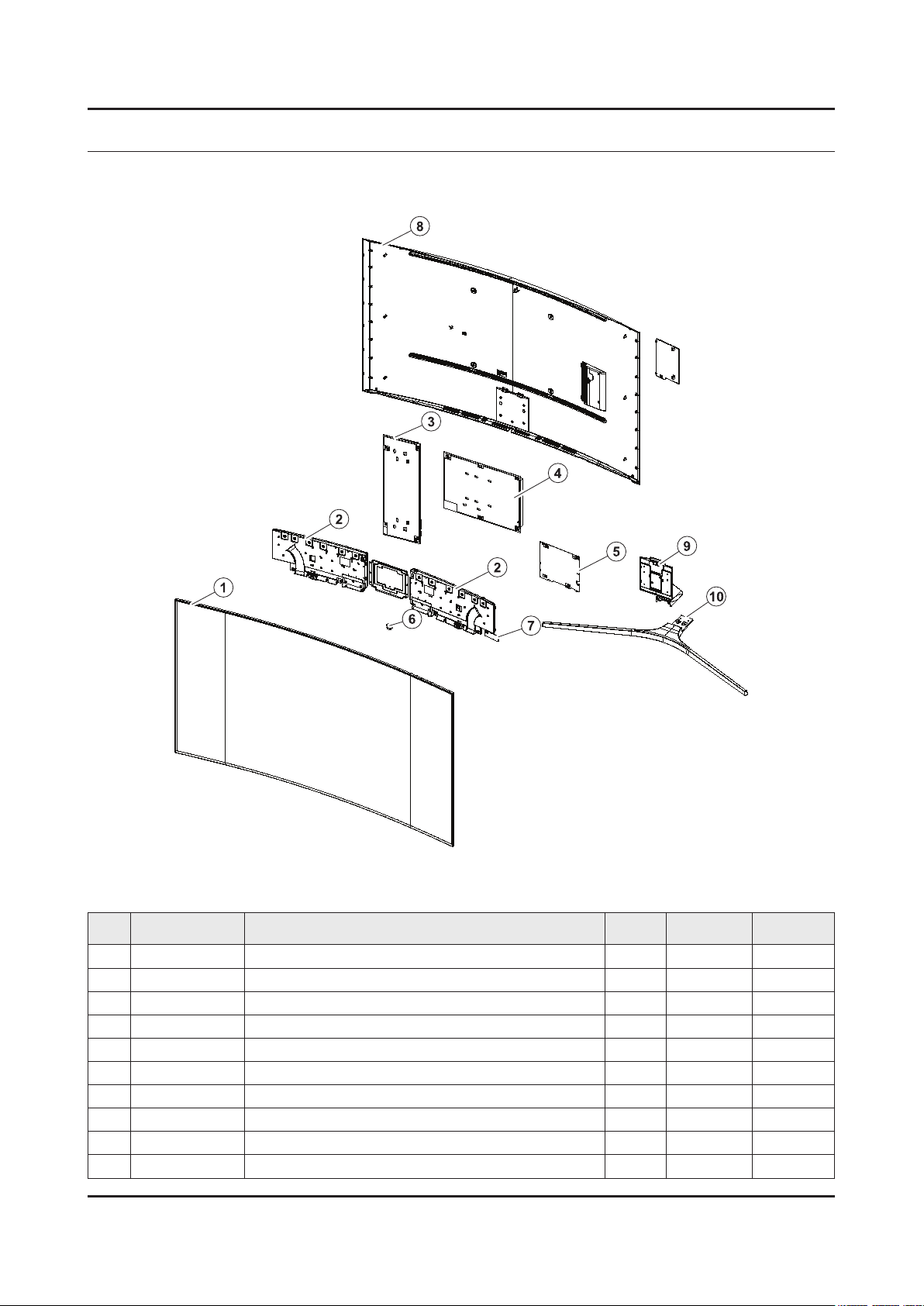
ANNEX. Exploded View & Part List [UE65KS9502TXXH FA01]
1-1. Exploded View
1-1-1. Parts List
No. Code No. Description & Specication Q’ty SA/SNA Remark
1 BN95-02727B PRODUCT LCD-SDC; CY-YK065FLLV2V/H,KS9800, 1 SA
2 BN96-40264A ASSY SPEAKER P-FRONT; TV-SPK,KS9800,6ohm, 1 SA
3 BN96-39394A ASSY SMPS P-PD BOARD; L65S9NC_KDYV,L65S9N 1 SA
4 BN44-00892A DC VSS-PD BOARD; L65S9NA_KSM,AC/DC,321W,1 1 SA
5 BN94-10846X ASSY PCB MAIN; UK9Y 1 SA
6 BN96-39802E ASSY BOARD P-IR FUNCTION TACT; KS9800,SJ1 1 SA
7 BN59-01239A NETWORK-WLAN CLIENT; WCK730B,USB 2.0,16P, 1 SA
8 BN96-36394A ASSY BRACKET P-STAND LINK; JS9500,65",EGI 1 SA
9 BN96-40089C ASSY COVER P-REAR; 65KS9800,PC+ABS+ED20%, 1 SA
10 BN96-40189B ASSY GUIDE P-STAND; 65KS9800,HGI-SGHC,NAT 1 SA
11 BN96-40192B ASSY STAND P-BOTTOM; 65KS9800,PC+ABS,SILV 1 SA
ANNEX-1
Page 30

ANNEX-2
ANNEX. Exploded View & Part List
1-2. ONE CONNECT Exploded View
1-2-1. Parts List
No. Code No. Description & Specication Q’ty SA/SNA Remark
1 BN96-40188F ASSY COVER P-TOP; 55KS9000,PC+ABS,V-0,BK0 1 SA
2 BN94-10924F ASSY PCB MISC-ONE CONNECT MINI; Y16 OCM P 1 SNA
3 BN63-15074E COVER-BOTTOM; OCM PLUS,PC+ABS,MOLD,V-0,BK 1 SA
Page 31

ANNEX-3
ANNEX. Exploded View & Part List
2-1. Electrical Parts List
Service Bom (SA: SERVICE AVAILABLE, SNA: SERVICE NOT AVAILABLE)
Level Location No. Code No. Description & Specication Q’ty SA/SNA Remark
UE65KS9502TXXH (FA01)
1 R001A BN90-08140C ASSY COVER REAR;UK9X,65" 1 SNA
0.2 R001A BN96-40089C ASSY COVER P-REAR;65KS9800,PC+ABS+ED20%, 1 SA
..3 BN61-13303A HOLDER-COVER;55KS8000,SI,MOLD,BK0008,HB 2 SNA
..3 CCM1 BN63-02183H SHEET-PROTECTION COVER;Rhcm,PE,T0.05,W13 2 SNA
..3 R001 BN63-14986A COVER-REAR;65KS9800,PC+ABS+ED20%,MOLD,V- 1 SNA
..3 BN63-15896A SHEET-PROTECTION COVER;65KS9800,PO,T0.07 1 SNA
..3 BN63-15896B SHEET-PROTECTION COVER;65KS9800,PO,T0.07 1 SNA
..3 BN63-15897A SHEET-PROTECTION COVER;65KS9800,PO,T0.07 1 SNA
..3 BN63-15897B SHEET-PROTECTION COVER;65KS9800,PO,T0.07 1 SNA
..3 BN64-03528D INLAY-TERMINAL SIDE;55KS7000,PET,T0.125, 1 SNA
..3 BN68-07835C LABEL-STICKER LICENSE;40K5500,PET,0.125, 1 SNA
1 S001A BN90-08160C ASSY STAND;UK9X,65" 1 SNA
0.2 SG01A BN96-40189B ASSY GUIDE P-STAND;65KS9800,HGI-SGHC,NAT 1 SA
..3 SCREW 6003-000003 SCREW-TAPTYPE;BH,+,-,B,M4,L10,ZPC(BLK),S 8 SA
..3 SCREW 6003-000282 SCREW-TAPTYPE;BH,+,-,B,M3,L8,ZPC(BLK),SW 1 SA
..3 6902-002059 BAG PE;HDPE/PE FOAM,T0.015/T0.5,W300,L40 1 SNA
..3 BN61-11627A BRACKET-STAND NECK;HGI,NATURAL 1 SNA
..3 BN61-11629A BRACKET-STAND NECK;EGI-SECC,NATURAL,T1.2 1 SNA
..3 BN61-11739G HOLDER-STAND CABLE;65KS9800,ABS,MOLD,BK0 1 SNA
..3 BN61-12070A BRACKET-STAND NECK;HGI,T2,NATURAL 1 SNA
..3 BN63-07556S SHEET-PROTECTION COVER;TOC,PO,W150,ROLL, 1 SNA
..3 BN63-13166B COVER-STAND NECK;65KS9800,PC+ABS+GF15%,M 1 SNA
..3 BN63-13339G COVER-STAND NECK FRONT;65KS9800,ABS,MOLD 1 SNA
..3 BN63-13399M COVER-STAND NECK REAR;65KS9800,PC+ABS,MO 1 SNA
..3 BN68-05603A LABEL-E PASS;ART PAPER 90G,W/W 1 SNA
..3 BN96-36799A ASSY ACCESSORY-SCREW;JS9K,6003-001494 (8 1 SNA
...4 SCREW 6003-001494 SCREW-TAPTYPE;BH,+,S,M4,L12,NI PLT,SWRCH 8 SA
...4 6902-002484 BAG SCREW;LDPE,T0.05,W70,L90,TRP,RECYCLE 1 SNA
0.2 SB02A BN96-40192B ASSY STAND P-BOTTOM;65KS9800,PC+ABS,SILV 1 SA
..3 SCREW 6003-001086 SCREW-TAPTYPE;BH,+,-,B,M3,L12,ZPC(BLK),S 6 SA
..3 6902-002462 BAG PE;HDPE/PE FOAM,T0.015/T0.5,W100,L50 2 SNA
..3 6902-002469 BAG PE;HDPE/PE FOAM,T0.015/T0.5,W160,L30 1 SNA
..3 BN60-00162E SPACER-FOAM;PE FOAM,ROLL,GRAY,T0.5,W20 0 SNA
..3 HOLDER-BOLT BN61-09494D HOLDER-BOLT;BH+,SWRCH18A,BLACK,PRESS,B T 4 SA
..3 BN61-12864A BRACKET-STAND LEFT;Al,NATURAL 1 SNA
..3 BN61-12900A BRACKET-STAND RIGHT;Al,NATURAL 1 SNA
..3 BN63-11118E SHEET-PROTECTION COVER;STANDARD ENCLOSUR 1 SNA
..3 RF01 BN67-00398L FOOT-RUBBER;SILICONE,GRAY,T2 6 SNA
..3 BN95-02918B ASSY COVER STAND SMT-TOP;65",KS9800,LIGH 1 SNA
...4 0204-006861 COATING;SMT-L100,CLEAR,0.928 0 SNA
...4 BN01-00160A TARGET-CHROMIUM CY;Chromium,99.95%,1800x 0 SNA
...4 BN01-00336A TARGET-ALUMINIUM CY;Al,99.9%,1724mm,132d 0 SNA
...4 BN63-13333A COVER-STAND TOP;JS9000 65",PC+ABS,MOLD,V 1 SNA
Page 32

ANNEX-4
ANNEX. Exploded View & Part List
Level Location No. Code No. Description & Specication Q’ty SA/SNA Remark
...4 BN68-03682A LABEL-STICKER;Label,W20,L10 1 SNA
1 BN90-08294J ASSY W/I;UKS* 1 SNA
0.2 BN81-08159Z A/S PART SET-ELEC W/I;LED TV ELEC spec-C 1 SNA
0.2 BN81-12851Y A/S PART SET-MECH W/I;UKS9800Y,U65KY* 1 SNA
1 BN91-17400B ASSY SHIELD;UK9X,65" 1 SNA
0.2 BN02-00102B TAPE-FILAMENT;#8917,0.15,25,50,WHITE 0 SNA
0.2 BN39-02207E LEAD CONNECTOR-POWER;65KS9800,UL21016,20 1 SA
0.2 BN39-02211E LEAD CONNECTOR-SUB ASSY;65KS9800,UL21451 1 SA
0.2 BN39-02220E LEAD CONNECTOR-SUB ASSY;78KS9800,UL21016 1 SA
0.2 BN39-02233C LEAD CONNECTOR-POWER;65KS9800,UL21016,22 1 SA
0.2 BN39-02239B LEAD CONNECTOR-DIMMING;65KS9800,UL21016, 1 SA
0.2 BN44-00892A DC VSS-PD BOARD;L65S9NA_KSM,AC/DC,321W,1 1 SA
0.2 WIFI BN59-01239A NETWORK-WLAN CLIENT;WCK730B,USB 2.0,16P, 1 SA
0.2 BN96-39802E ASSY BOARD P-IR FUNCTION TACT;KS9800,SJ1 1 SA
0.2 BN96-40209A FFC CABLE;49K6200,Wrinkle,L350,51P 1 SA
0.2 BN96-40264A ASSY SPEAKER P-FRONT;TV-SPK,KS9800,6ohm, 1 SA
0.2 BN96-40394B FFC CABLE;65KS9800,Wrinkle,L300,41P,- 1 SA
1 M0017 BN91-17407X ASSY CHASSIS;UK9Y 1 SNA
0.2 M0014 BN94-10846X ASSY PCB MAIN;UK9Y 1 SA
..3 T0073 AA63-01141D GASKET-EMI;42D5,Conductive Fabric,T1.5,W 1 SNA
..3 BN62-00185A HEAT SINK-ES;PDP42D450,A6063,W14,L18,BLA 1 SNA
..3 BN62-00816A HEAT SINK-PS;55KS9000,A1050,T6.3,W145,L1 1 SNA
..3 BN63-15050D COVER-TERMINAL SIDE;55KS9000,HIPS,MOLD,H 1 SA
..3 BN97-10674D ASSY SMD;UKS9800 1 SNA
...4 0406-001438 DIODE-TVS;SMCJ14A,15.6V,17.2V,1MAV,6.5VP 3 SA
...4 0406-001628 DIODE-TVS;AOZ8804ADI,6V,1MAV,5A,TP 1 SA
...4 0406-001635 DIODE-TVS;SMF5.0A,6.4V,6.7V,7V,200MAV,20 6 SA
...4 0504-000126 TR-DIGITAL;KSR1101,NPN,200mW,4.7K/4.7K,S 2 SA
...4 0505-001844 FET-SILICON;SI4435DDY-T1-GE3,P,30V,-11.4 4 SA
...4 0505-002598 FET-SILICON;AP2317GN,P,20V,-4.2A,0.052oh 1 SA
...4 0505-002893 FET-SILICON;AO4801AS,P,30V,-5A,2W,SOIC-8 1 SA
...4 0505-003264 FET-SILICON;AO4447AL,P,30V,-17A,7mohm,3. 1 SA
...4 0505-003397 FET-SILICON;2N7002K,N,60V,0.38A,1.19ohm, 1 SA
...4 0505-003507 FET-SILICON;AO3424,N,30V,3.8A,1.4W,SOT-2 13 SA
...4 0801-003603 IC-CMOS LOGIC;MC74LCX244MN2TWG,Octal buf 1 SA
...4 1001-001998 IC-ANALOG MULTIPLEX;NX3DV221GM,USB switc 1 SA
...4 1006-001576 IC-DRIVER/RECEIVER;MAX3221ECPWR,TSSOP,16 1 SA
...4 1103-001564 IC-EEPROM;S-24C512CI-J800,512Kbit,64Kx8, 1 SA
...4 1105-002704 IC-DDR4 SDRAM;K4F8E304HB-MGCH,LPDDR4-SDR 3 SA
...4 1201-004003 IC-AUDIO AMP;TAS880021,TSSOP,48P,12.5x6. 3 SA
...4 1203-004364 IC-VOL. DETECTOR;RT9818C-42PV,SOT-23,3P, 1 SA
...4 1203-008105 IC-POSI.FIXED REG.;S-13A1D33-E800,HSOP,8 1 SNA
...4 1203-008391 IC-DC/DC CONVERTER;AOZ1269QI-02,QFN-23L, 1 SA
...4 1203-008392 IC-VOL. DETECTOR;S-6414AAB-L800X,TSOT-23 1 SA
...4 1203-008732 IC-DC/DC CONVERTER;SYD104ADC,TSOT-23,6,3 1 SA
...4 1203-008733 IC-DC/DC CONVERTER;AOZ1236QI-02,QFN,23,4 1 SA
...4 1203-008735 IC-DC/DC CONVERTER;AOZ1267QI-02,QFN,23,4 1 SA
Page 33

ANNEX-5
ANNEX. Exploded View & Part List
Level Location No. Code No. Description & Specication Q’ty SA/SNA Remark
...4 1204-003679 IC-DECODER;SDP1501,FCPBGAH,1230P,35*35mm 1 SA
...4 1205-004822 IC-SWITCH;TPS22965DSGR,SON,8P,2x2x0.75mm 3 SNA
...4 1205-005554 IC-REPEATER;TMDS181,VQFN,48P,7x7mm,PLAST 1 SA
...4 IS01 1209-002183 IC-SENSOR;S-5851AAA-M6T1U,SOT,6Z30,2.9x1 1 SA
...4 1405-001271 VARISTOR;35V,20VDC,5A,1.0x0.5mm,TP,100V, 11 SA
...4 2007-000039 R-CHIP;0ohm,1%,1/10W,TP,1608 8 SA
...4 2007-000146 R-CHIP;6.8Kohm,5%,1/16W,TP,1005 1 SNA
...4 2007-000171 R-CHIP;0ohm,5%,1/16W,TP,1005 93 SNA
...4 2007-000932 R-CHIP;470ohm,5%,1/16W,TP,1005 1 SNA
...4 2007-001292 R-CHIP;33ohm,5%,1/16W,TP,1005 12 SNA
...4 2007-001298 R-CHIP;51ohm,5%,1/16W,TP,1005 1 SNA
...4 2007-007107 R-CHIP;100Kohm,1%,1/16W,TP,1005 30 SNA
...4 2007-007231 R-CHIP;110Kohm,1%,1/10W,TP,1608 1 SA
...4 2007-007306 R-CHIP;100ohm,1%,1/16W,TP,1005 26 SNA
...4 2007-007312 R-CHIP;20Kohm,1%,1/16W,TP,1005 11 SA
...4 2007-007313 R-CHIP;6.8Kohm,1%,1/16W,TP,1005 4 SA
...4 2007-007316 R-CHIP;3.3Kohm,1%,1/16W,TP,1005 3 SNA
...4 2007-007334 R-CHIP;200Kohm,1%,1/16W,TP,1005 4 SNA
...4 2007-007517 R-CHIP;240ohm,1%,1/16W,TP,1005 17 SNA
...4 2007-007520 R-CHIP;20ohm,1%,1/10W,TP,1608 12 SA
...4 2007-007627 R-CHIP;16Kohm,1%,1/16W,TP,1005 1 SA
...4 2007-007798 R-CHIP;10ohm,1%,1/16W,TP,1005 1 SA
...4 2007-007942 R-CHIP;1Mohm,1%,1/16W,TP,1005 2 SNA
...4 2007-008136 R-CHIP;36Kohm,1%,1/16W,TP,1005 1 SA
...4 2007-008263 R-CHIP;3Kohm,1%,1/16W,TP,1005 2 SA
...4 2007-008269 R-CHIP;51Kohm,1%,1/16W,TP,1005 1 SA
...4 2007-008298 R-CHIP;49.9ohm,1%,1/16W,TP,1005 17 SA
...4 2007-008391 R-CHIP;6.34Kohm,1%,1/16W,TP,1005 1 SA
...4 2011-001261 R-NETWORK;33ohm,5%,1/16W,L,CHIP,8P,TP,2. 6 SA
...4 2011-001344 R-NETWORK;100ohm,5%,1/16W,L,CHIP,8P,TP,2 6 SA
...4 AD480 2203-000233 C-CER,CHIP;0.1nF,5%,50V,C0G,TP,1005 12 SA
...4 AD480 2203-000254 C-CER,CHIP;10nF,10%,16V,X7R,TP,1005 1 SA
...4 AD480 2203-000278 C-CER,CHIP;0.01nF,0.5pF,50V,C0G,TP,1005 1 SA
...4 AD480 2203-000386 C-CER,CHIP;0.015nF,5%,50V,C0G,TP,1005 3 SA
...4 AD480 2203-000714 C-CER,CHIP;3.3nF,10%,50V,X7R,TP,1005 12 SA
...4 AD480 2203-005054 C-CER,CHIP;0.0047nF,0.25pF,50V,NP0,TP,10 2 SA
...4 AD480 2203-006048 C-CER,CHIP;100nF,10%,10V,X7R,TP,1005 1 SA
...4 AD480 2203-006324 C-CER,CHIP;2200nF,10%,10V,X5R,TP,1608 17 SA
...4 AD480 2203-006377 C-CER,CHIP;4700nF,10%,25V,X5R,TP,2012 3 SNA
...4 AD480 2203-006844 C-CER,CHIP;470nF,10%,10V,X5R,TP,1005 3 SA
...4 AD480 2203-007240 C-CER,CHIP;22000nF,20%,6.3V,X5R,TP,1608( 87 SA
...4 2409-001338 C-POLYMER ,CHIP;47uF,20%,6.3V,TP,3.2x1.6 1 SA
...4 2703-004724 INDUCTOR-SMD;8.2uH,20%,4T,0.072Ohm,2300m 12 SA
...4 2801-004021 CRYSTAL-SMD;24.576MHz,20ppm,28-AAN,12pF, 1 SA
...4 3301-001364 BEAD-SMD;1000ohm,1608,TP,1085ohm/108MHz, 7 SNA
...4 3709-001782 CONNECTOR-CARD SLOT;68P,1.27mm,ANGLE,AU, 1 SA
...4 3710-004144 CONNECTOR-SOCKET;44P,1R,0.5mm,SMD-A,AU,B 2 SA
Page 34

ANNEX-6
ANNEX. Exploded View & Part List
Level Location No. Code No. Description & Specication Q’ty SA/SNA Remark
...4 3711-007741 CONNECTOR-HEADER;BOX,14P,2R,2.0mm,ANGLE, 1 SA
...4 EH01 3711-007803 HEADER-BOARD TO CABLE;BOX,12P,1R,1.25mm, 1 SA
...4 EH01 3711-007838 HEADER-BOARD TO CABLE;BOX,6P,1R,1.25mm,S 1 SA
...4 3711-009106 CONNECTOR-HEADER;BOX,20P,2R,2mm,ANGLE,SN 1 SA
...4 3722-003199 JACK-MODULAR;8P/8C,Y,ANGLE,NONE,AU,1PORT 1 SA
...4 3722-003394 JACK-PHONE;1P/6C,AU,BLK,ANGLE,3.6PI,9x14 1 SA
...4 6302-001376 GASKET-SMD;,,CONDUCTIVE FABRIC,T14,W43,L 6 SNA
...4 BN41-02505A PCB-MAIN;KS9700/KS9800,FR-4,4L,1.2T,214x 1 SNA
...4 CB07 BN61-13312B BRACKET-PCB;55KS8000,SK5,T0.3,13.7,11.4, 4 SNA
...4 BN97-10856B ASSY MICOM-SUB;JMMICOM_EU_TV,UWQ60,W25Q4 1 SNA
....5 1107-002226 IC-NOR FLASH;W25Q40CLSSIP,4Mbit,SOIC,8P, 1 SA
...4 BN97-10858A ASSY MICOM-MAIN;T-JZMDEUC,UWQ60,KLM8G1GE 1 SNA
....5 1107-002362 IC-EMMC;KLM8G1GEND-B031,8GB,64Gb MLC x 1 1 SNA
..3 BN97-10873A ASSY DRM;Jazz M,DVB,NagSam, MAC, HDCP, C 1 SNA
...4 BN46-00109H KEY CODE-CERTIFICATION;MAC,TV/AV,General 1 SNA
...4 BN46-00110P KEY CODE-CERTIFICATION;MIRACAST(HDCP2.2) 1 SNA
...4 BN46-00496A KEY CODE-CERTIFICATION;Jazz-M,Nagra CSC 1 SNA
...4 BN46-00514A KEY CODE-CERTIFICATION;CI PLUS,Jazz M, J 1 SNA
..3 M0131 MD63-00103A GASKET-TAPE;GRANDSLAM,Conductive Fabric, 1 SNA
1 BN91-17868A ASSY FIXING-JACKPACK;Y16 OCM 1 SA
0.2 AA68-02626A LABEL-PQS;ART,W40,L12,SERIAL 2 SNA
0.2 BN39-02210A ONECONNECTMINI CABLE;KS7000~KS9000,44P,L 1 SA
0.2 RB01 BN63-15074E COVER-BOTTOM;OCM PLUS,PC+ABS,MOLD,V-0,BK 1 SA
..3 0103-005041 RESIN PC ABS;FR3200TV,901408,BK0008,1.2m 100 SNA
0.2 BN69-13267A BOX ACCESSORY;CB,SW-E,L373,W308 1 SNA
0.2 OCMBD BN94-10924F ASSY PCB MISC-ONE CONNECT MINI;Y16 OCM P 1 SNA
..3 AH62-00243A HEAT SINK-ES;HT-D550,A6063,W23,L23,BLACK 1 SA
..3 OCM BD BN97-10869F ASSY SMD;7/8/9 SERIES 1 SA
...4 DS01A 0401-001056 DIODE-SWITCHING;MMBD4148SE,100V,200mA,SO 2 SA
...4 DR01A 0402-001614 DIODE-RECTIFIER;S1G,400V,1A,DO-214AC,TP 2 SA
...4 0403-001783 DIODE-ZENER;BZB84-C6V2,5.8~6.6V,300mW,SO 4 SNA
...4 0404-001404 DIODE-SCHOTTKY;BAT721C,40V,200mA,SOT-23, 4 SA
...4 0404-001881 DIODE-SCHOTTKY;SS3040-HE,40V,3000mA,SOD- 3 SA
...4 0406-001200 DIODE-TVS;RClamp0504F,6V,1MAV,TP 3 SA
...4 0406-001290 DIODE-TVS;3.0SMCJ20A,22.2V,24.5V,5MAV,30 2 SNA
...4 0501-000002 TR-SMALL SIGNAL;KSA812,PNP,150mW,SOT-23, 1 SNA
...4 0501-000445 TR-SMALL SIGNAL;KTC3875S-Y,NPN,150mW,SOT 18 SC
...4 0801-003292 IC-CMOS LOGIC;7WB66,Bus Switch,MAB08A,8P 1 SA
...4 0801-003598 IC-CMOS LOGIC;TC7SZ00FU,2-Input NAND Gat 1 SA
...4 0801-003604 IC-CMOS LOGIC;NL17SZ17DFT2G,SC-70,5P,TP, 1 SA
...4 1103-001583 IC-EEPROM;BR24T02FJ-WGE2,2Kbit,256x8,SOP 4 SNA
...4 1203-007697 IC-DC/DC CONVERTER;LNBH26SPQR,QFN,24,4x4 1 SA
...4 1203-008102 IC-POSI.FIXED REG.;S-13A1D12-E800,HSOP,8 2 SNA
...4 1203-008345 IC-POSI.ADJUST REG.;S-13A1ADJ-E800X,HSOP 1 SA
...4 1204-003677 IC-DECODER;SDP1503,FCPBGAH,396P,18*18mm, 1 SA
...4 1205-005519 IC-SWITCH;ET20163,SOT23-5,5P,2.95x3.02mm 4 SA
...4 1205-005537 IC-REPEATER;TCA9517,VSSOP,8P,3.00x3.00mm 1 SA
Page 35

ANNEX-7
ANNEX. Exploded View & Part List
Level Location No. Code No. Description & Specication Q’ty SA/SNA Remark
...4 2007-000879 R-CHIP;4.7ohm,1%,1/10W,TP,1608 1 SA
...4 2007-000999 R-CHIP;510ohm,1%,1/10W,TP,1608 1 SA
...4 2007-002900 R-CHIP;11Kohm,1%,1/10W,TP,1608 1 SNA
...4 2007-007108 R-CHIP;43.2Kohm,1%,1/16W,TP,1005 2 SA
...4 2007-007139 R-CHIP;47Kohm,1%,1/16W,TP,1005,T0.35 12 SA
...4 2007-007309 R-CHIP;12Kohm,1%,1/16W,TP,1005,T0.35 1 SA
...4 2007-007488 R-CHIP;75Kohm,1%,1/16W,TP,1005 7 SNA
...4 2007-007587 R-CHIP;3.6Kohm,1%,1/16W,TP,1005 2 SNA
...4 2007-007766 R-CHIP;2Kohm,1%,1/16W,TP,1005 27 SNA
...4 2007-007767 R-CHIP;200ohm,1%,1/16W,TP,1005 10 SA
...4 2007-007868 R-CHIP;90.9ohm,1%,1/10W,TP,1608 2 SA
...4 2007-007992 R-CHIP;1ohm,1%,1/10W,TP,1608 1 SA
...4 2007-008015 R-CHIP;75ohm,1%,1/16W,TP,1005 1 SNA
...4 2007-008067 R-CHIP;21Kohm,1%,1/10W,TP,1608 2 SA
...4 2007-008134 R-CHIP;12.4Kohm,1%,1/16W,TP,1005 5 SC
...4 2007-008167 R-CHIP;120Kohm,1%,1/16W,TP,1005 1 SC
...4 2007-008294 R-CHIP;33ohm,1%,1/16W,TP,1005 6 SA
...4 2011-001449 R-NETWORK;22ohm,5%,1/16W,L,4P,TP,1.0x1.0 4 SA
...4 AD480 2203-000359 C-CER,CHIP;0.15nF,5%,50V,C0G,TP,1005,0.5 3 SNA
...4 AD480 2203-000425 C-CER,CHIP;0.018nF,5%,50V,C0G,TP,1005 2 SA
...4 AD480 2203-000585 C-CER,CHIP;0.22nF,10%,50V,X7R,TP,1005 1 SA
...4 AD480 2203-000812 C-CER,CHIP;0.033nF,5%,50V,C0G,TP,1005 6 SA
...4 AD480 2203-000940 C-CER,CHIP;0.47nF,10%,50V,X7R,TP,1005 1 SA
...4 AD480 2203-002285 C-CER,CHIP;10nF,10%,50V,X7R,TP,1005 5 SNA
...4 AD480 2203-005083 C-CER,CHIP;220nF,10%,50V,X7R,TP,1608,0.8 4 SA
...4 AD480 2203-006562 C-CER,CHIP;1000nF,10%,10V,X5R,TP,1005 40 SNA
...4 AD480 2203-006824 C-CER,CHIP;4700nF,10%,10V,X5R,TP,1608 3 SNA
...4 AD480 2203-007269 C-CER,CHIP;22000nF,20%,10V,X5R,TP,2012(2 30 SA
...4 2703-000213 INDUCTOR-SMD;470nH,10%,1.35Ohm,35mA,15,M 1 SA
...4 2703-001938 INDUCTOR-SMD;56nH,5%,1005,1.5Ohm,200mA,1 7 SA
...4 2703-004868 INDUCTOR-SMD;6.8uH,20%,4.0T,0.043Ohm,250 2 SA
...4 2703-005191 INDUCTOR-SMD;1.5uH,20%,4.5,0.02Ohm,5300m 2 SA
...4 2703-005194 INDUCTOR-SMD;3.3uH,20%,4.5,0.03Ohm,4500m 2 SA
...4 2801-005372 CRYSTAL-SMD;24.576MHz,20ppm,HCX-3SB,12 p 1 SA
...4 3701-001967 CONNECTOR-HDMI;19P,A,FEMALE,AU,0.5mm,BLK 4 SA
...4 3707-001104 CONNECTOR-OPTICAL;ANGLE,SPDIF 1 SA
...4 3722-003457 JACK-USB;4P/1C,NI,BLK,ANGLE,A,2.0,13.1x1 3 SA
...4 BN40-00324A TUNER-DTV AIR CABLE SAT;DNTT243H6A,DNTT2 1 SA
...4 BN41-02510A PCB-OCM;KS8000/KS9000,FR-4,4L,1.2T,199x6 1 SNA
0.2 T001A BN96-40188F ASSY COVER P-TOP;55KS9000,PC+ABS,V-0,BK0 1 SA
..3 6902-001408 BAG PE;HDPE/PE FOAM,T0.015/T0.5,W120,L25 1 SNA
..3 M0131 BN63-00558A GASKET-EMI;GG15AS,Conductive Fabric,T3,W 1 SNA
..3 BN63-07272J SHEET-PROTECTION COVER;OCM+,PE,W205,Roll 0 SNA
..3 T001 BN63-15073F COVER-TOP;OCM PLUS,PC+ABS,MOLD,V-0,BLACK 1 SNA
...4 0103-005041 RESIN PC ABS;FR3200TV,901408,BK0008,1.2m 100 SNA
1 BN92-20056A ASSY P/MATERIAL;UK9X,65" 1 SNA
0.2 6902-001954 BAG ROLL;HDPE/PE FOAM,HDPE T0.018mm,T0.2 3 SNA
Page 36

ANNEX-8
ANNEX. Exploded View & Part List
Level Location No. Code No. Description & Specication Q’ty SA/SNA Remark
0.2 6902-002233 BAG AIR;LDPE,-,T0.2,W900,L1850,TRP,-,-,- 1 SNA
0.2 6922-000003 BAND;PP,T0.8,W18,L1650M,TRP,DA69-90145A 1 SNA
0.2 BN02-00319B TAPE-OPP;OPP,T0.05,W75,L800m,CLEAR 3 SNA
0.2 BN68-02422B LABEL-WARNING;ALL,ART,T0.05,W240,L100,Wh 1 SNA
0.2 BN69-03982J PACKING ANGLE;ALL,PAPER,-,-,-,-,-,-,- 1 SNA
0.2 BN69-05418M WRAP;T0.017,500,2000000,2000000,500 0 SNA
0.2 BN69-06640E PAD-PACKING;TRUCK PAD,CB,-,,W410,L2500,, 1 SNA
0.2 BN69-06642B PAD-DP SHEET;PAD,CB,SW4,,W1500,L1100,,,, 1 SNA
0.2 BN69-11115L PALLET-DP WOODEN;65" DMD,WOOD,-,W1150,L1 1 SNA
0.2 BN69-13394A CUSHION-SET SIDE;65KS9800,EPS,16.7g/l,WH 1 SNA
0.2 BN69-13395A CUSHION-SET;65KS9800,EPS,16.7g/l,WHT 1 SNA
..3 0103-005099 RESIN EPS;BASF303,Natural,Natural 1408 SNA
0.2 BN69-14366B PAD-CUSHION FRONT;65KS9800,CB,DW2+EPS,W7 1 SNA
1 BN92-20068C ASSY BOX;UK9X,65" 1 SNA
0.2 BH68-00662A LABEL BOX;ALL,ART,90g,W60,L110,WHT,NO SI 1 SNA
0.2 BN68-05640A LABEL BOX;ALL,ART,90g,W110,L130,EUROPE,L 1 SNA
0.2 BN69-13965C BOX UNIT;65KS9500,CB,DW4,F1,L1575,W215,H 1 SNA
1 BN92-20074T ASSY LABEL;UK9Y 1 SNA
0.2 0203-001598 TAPE-FILAMENT;#8915,0.15,12,55000,CLR 0 SNA
0.2 BN68-06708G LABEL-RATING;Monitor,WW,PP,T0.161,W93,L7 1 SNA
0.2 BN68-07519A LABEL-ENERGY;ALL JORDAN,WW,PP,T0.135,W60 1 SNA
0.2 BN68-07877E LEAFLET-QUICK SETUP GUIDE;KS9800,EU,W/P, 1 SNA
1 ACCE1 BN92-20086C ASSY ACCESSORY;UK9Y 1 SNA
0.2 ACCE2 BN96-39422Y ASSY ACCESSORY-CABLE;UK9W 1 SNA
..3 T0268 3903-001118 CBF-POWER CORD;DT,EU,Angle,2P(C7),250V,2 1 SA
..3 4301-000101 BATTERY-ALKALINE;1.5V,1650mAH,LR6,14.5x5 2 SNA
..3 6902-001965 BAG PE;LDPE,BIOBASED,T0.05,W200,L300,TRP 1 SNA
..3 BN59-01242A REMOCON-SMART CONTROL;2016 TV,Samsung,14 1 SA
..3 M9889 BN63-01798B CLOTH-CLEAN;CLOTH,sea blue,ToC 1 SA
..3 EH03A BN96-36071C ASSY HOLDER P-RING;LED,JS9K,ABS,BLK 1 SNA
...4 6902-002497 BAG ZIPPER;LDPE,T0.05,W100,L250,TRP,RECY 1 SNA
...4 AH365 BN61-10572A HOLDER-WALL RING;HU9000 78",ABS,BLACK,HB 4 SA
....5 0103-004609 RESIN ABS;HF-0680U,K21294,BK0007,HB,High 48 SNA
0.2 ACCE4 BN96-39432Q ASSY ACCESSORY-MANUAL;UK9Y 1 SNA
..3 6902-001964 BAG PE;LDPE,BIOBASED,T0.03,W200,L300,TRP 1 SNA
..3 T0527 BN68-00513A LABEL-E PASS;ALL MODEL,WW,YUPO,W50,L15,W 2 SNA
..3 BN68-03548J LEAFLET-WARRANTY;comm,Samsung,17Lang,Mid 1 SNA
..3 BN68-04972E LEAFLET-REGULATORY GUIDE;ALL,SAMSUNG,W/W 1 SNA
..3 BN68-07598A LEAFLET-FICHE;ALL,W/P,0 1 SNA
..3 BN68-07860E MANUAL USERS;KS9800,XH,W/P,EURO B5 1 SNA
..3 BN68-08099A LEAFLET;JAZZ-M,EUROPE,W/P,W176,L250,4COL 1 SNA
0.2 FC05A BN96-40566A ASSY COVER P-TERMINAL;65KS9800,PC+ABS+ED 1 SA
..3 6902-000294 BAG PE;LDPE,T0.05,W160,L250,TRP,-,- 1 SNA
..3 BN63-15663A COVER-TERMINAL;65KS9800,PC+ABS+ED20%,MOL 1 SNA
1 BN92-20416A ASSY LABEL POP;BN68-07972A 1 SNA
0.2 BN68-07972A LABEL POP-HIGHLIGHT;KS9000,PET,T0.1,W119 1 SNA
1 BN95-02727B PRODUCT LCD-SDC;CY-YK065FLLV2V/H,KS9800, 1 SA
Page 37

ANNEX-9
ANNEX. Exploded View & Part List
Level Location No. Code No. Description & Specication Q’ty SA/SNA Remark
0.2 SCREW 6001-003016 SCREW-MACHINE;PWH,+,M3.0,L5.0,ZPC(WHT),S 4 SA
0.2 SCREW 6001-003075 SCREW-MACHINE;BH,+,M3,L4,ZPC(WHT),SWRCH1 12 SA
0.2 6001-003168 SCREW-MACHINE;CH,+,M3,L5,ZPC(BLK),SWRCH1 8 SNA
0.2 BN60-01460A SPACER-FOAM;78KS9800,PU FOAM,ROLL,BLACK, 3 SNA
0.2 BN62-00604A PAD GAP-THERMAL;SI,T5.5,L35,H35,GRAY 1 SNA
0.2 BN68-05722A LABEL-E PASS;POLYPROPYLENE,NON-COATING 1 SNA
0.2 BN90-08247A ASSY MISC-BLU;Y16,LCM 1 SNA
..3 SCREW 6001-003075 SCREW-MACHINE;BH,+,M3,L4,ZPC(WHT),SWRCH1 24 SA
..3 BN02-00508B TAPE PET;49KS7000,PET,T0.05,W10,L45,BLAC 5 SNA
..3 BN61-13208A FRAME-CHASSIS REAR LEFT RIGHT;65KS9800,P 2 SNA
..3 BN61-13648A OPTICAL SHEET-DBEF;16Y_KS9000_65INCH_DBE 1 SNA
..3 BN61-13649A OPTICAL SHEET-HIGH COLOR;16Y_KS9000_65IN 1 SNA
..3 BN61-13650A OPTICAL SHEET-COMPLEX;16Y_KS9000_65INCH_ 1 SNA
..3 BN61-13866A DIFFUSER PLATE;16Y_KS9800_65INCH_DIFFUSE 1 SNA
..3 BN96-40062A ASSY LED BAR P;65inch_SDC_C,CEM3 6 SNA
..3 BN96-40063A ASSY LED BAR P;65inch_SDC_B,CEM3 2 SNA
..3 BN96-40064A ASSY LED BAR P;65inch_SDC_A,CEM3 2 SNA
..3 BN96-40502A ASSY CHASSIS REAR P;65KS9800,EGI-SECC 1 SNA
...4 SCREW 6001-002759 SCREW-MACHINE;CH,+,M3,L4,ZPC(BLK),SWRCH1 8 SA
...4 SCREW 6001-003016 SCREW-MACHINE;PWH,+,M3.0,L5.0,ZPC(WHT),S 8 SA
...4 M0909 AA63-01387A GASKET-EMI;SP-P300M,Conductive Fabric,T2 12 SNA
...4 T0139 AA65-30007A HOLDER-WIRE;PA66,PA66,GRAY,V0 2 SNA
...4 BN02-00102B TAPE-FILAMENT;#8917,0.15,25,50,WHITE 12 SNA
...4 BN02-00485A TAPE PET;KS7000,PET,T0.05,W7,L50,BLACK 8 SNA
...4 CB20 BN61-08936C BRACKET-WALL;HGI-SGHC,T2,BLACK,BLACK ED- 4 SNA
...4 BN61-11448A SUPPORT-PLATE;LED N9 65inch,PC,V-2,WHITE 30 SNA
...4 BN61-11466A HOLDER-SOURCE PCB;LED N9,ABS,BLACK,HB,K2 8 SNA
...4 BN61-11764A SUPPORT-PLATE;LED N9 65inch,PC,V-2,WHITE 10 SNA
...4 BN61-13557A BRACKET-WIRE;55KS7000,SW-C,T1,60,SILVER 2 SA
...4 BN61-13557C BRACKET-WIRE;55KS7000,SW-C,T1,280,SILVER 2 SA
...4 BN61-13557F BRACKET-WIRE;55KS7000,SW-C,T1,SILVER,ZIN 2 SA
...4 BN61-13758A BRACKET-CLIP;65KS9800,SK5,T0.2,NATURAL,W 11 SNA
...4 BN61-14077A HOLDER-REAR TOP;65KS9800,ABS,MOLD,BK0007 12 SNA
...4 BN62-00700A INSULATOR-SMPS;Y15 N9000 88,PC,BLACK,L70 2 SNA
...4 BN63-15451A INSULATOR-SMPS;55KS9800,PC,BLACK,L400,W2 1 SNA
...4 BN63-15452A INSULATOR-SHEET;55KS9800,PC,BLACK,L249,W 1 SNA
...4 BN63-15906A INSULATOR-SOURCE PCB COVER LEFT;65KS9800 1 SNA
...4 BN63-15907A INSULATOR-SOURCE PCB COVER RIGHT;65KS980 1 SNA
...4 CC04 BN64-03526A CHASSIS-REAR;65KS9800,EGI-SECC,PRESS,T1, 1 SNA
...4 T0527 BN68-00513A LABEL-E PASS;ALL MODEL,WW,YUPO,W50,L15,W 1 SNA
...4 BN96-40569A FFC CABLE;65KS9800,Fold,L650,30P,65KS980 1 SNA
...4 BN96-40570A FFC CABLE;65KS9800,Fold,L450,30P,65KS980 1 SNA
...4 BN96-40571A FFC CABLE;65KS9800,Fold,L850,30P,65KS980 1 SNA
...4 BN96-40572A FFC CABLE;65KS9800,Fold,L1050,30P,65KS98 1 SNA
...4 BN96-40573A FFC CABLE;65KS9800,Fold,L1300,30P,65KS98 1 SNA
...4 BN96-40574A FFC CABLE;65KS9800,Fold,L400,30P,65KS980 1 SNA
...4 BN96-40575A FFC CABLE;65KS9800,Fold,L600,30P,65KS980 1 SNA
Page 38

ANNEX-10
ANNEX. Exploded View & Part List
Level Location No. Code No. Description & Specication Q’ty SA/SNA Remark
...4 BN96-40576A FFC CABLE;65KS9800,Fold,L850,30P,65KS980 1 SNA
...4 BN96-40577A FFC CABLE;65KS9800,Fold,L1100,30P,65KS98 1 SNA
...4 BN96-40578A FFC CABLE;65KS9800,Fold,L250,30P,65KS980 1 SNA
..3 BN96-40510A ASSY FRAME P-MIDDLE BOTTOM;65KS9800,PC+A 1 SNA
...4 BN60-01163C SPACER-SILICONE;Y15 JU7K 65",Si,L710,GRA 2 SNA
...4 BN61-13585A FRAME-MIDDLE BOTTOM;65KS9800,PC+GF10%,V- 1 SNA
..3 BN96-40973A ASSY FRAME P-CHASSIS REAR TOP;65KS9800,P 1 SNA
...4 BN61-13206A FRAME-CHASSIS REAR TOP;65KS9800,PC+GF10% 1 SNA
..3 BN96-40974A ASSY FRAME P-CHASSIS REAR BOTTOM;65KS980 1 SNA
...4 BN60-01451A SPACER-PET;78KS9800,PET,L29.01,WHITE,T0. 2 SNA
...4 BN60-01452A SPACER-PET;78KS9800,PET,L29.01,WHITE,T0. 2 SNA
...4 BN61-13207A FRAME-CHASSIS REAR BOTTOM;65KS9800,PC+GF 1 SNA
0.2 TCON BN95-02590A ASSY T CON;KS9800 65inch,Jazz-FT 1 SA
..3 BN62-00610B HEAT SINK-PS;HU9000,A1050,W120,L65,BLACK 1 SNA
..3 BN62-00820A HEAT SINK-PS;65KS9800,A1050,W137,L103,BL 1 SNA
..3 BN97-10885A ASSY SMD;KS9800 65inch,Jazz-FT,BN95-0259 1 SNA
...4 0202-001608 SOLDER-WIRE FLUX;LFC7-107,D0.8,99.3Sn/0. 0 SNA
...4 0202-001899 SOLDER-CREAM;M705-GRN360-K2-VT,20-38um,S 10 SNA
...4 0403-001164 DIODE-ZENER;MMSZ5232B,5.32~5.88V,500mW,S 3 SA
...4 0403-001831 DIODE-ZENER;KDZ12B,12~13.5V,1000mW,SOD-1 1 SA
...4 0403-002014 DIODE-ZENER;KDZ16B,16.2~18.3V,1000mW,SOD 2 SNA
...4 0404-001307 DIODE-SCHOTTKY;SSC54,40V,5000mA,DO-214AB 1 SA
...4 0404-001640 DIODE-SCHOTTKY;SS1060HEWS,60V,1000mA,SOD 1 SA
...4 0404-001953 DIODE-SCHOTTKY;MBRA340F-HAF,40V,3000mA,S 3 SA
...4 0406-001317 DIODE-TVS;SMAJ14A,15.6V,17.2V,1MAV,6.5VP 3 SNA
...4 0406-001643 DIODE-TVS;1SMA33AT3G,36.7V,38.65V,40.6V, 1 SNA
...4 0406-001691 DIODE-TVS;SESD8008MUTAG,5.5V,7V,8.5V,0.5 12 SA
...4 0501-000465 TR-SMALL SIGNAL;MMBT3904,NPN,350mW,SOT-2 3 SA
...4 0505-002660 FET-SILICON;Si2308BDS,N,60V,2.3A,0.156oh 1 SNA
...4 0505-003205 FET-SILICON;DMG4435SSS-13,P,30V,-7.3A,1. 1 SA
...4 0505-003391 FET-SILICON;AOD2922,N,100V,8A,140Mohm,18 1 SA
...4 EL02 0601-002037 LED;SMD(TOP VIEW),BLUE,1.6x0.8mm,465/470 2 SA
...4 0801-003580 IC-CMOS LOGIC;TC7WB66CFK,SSOP,8P,2.0X2.3 3 SA
...4 1105-002772 IC-DDR3 SDRAM;K4B1G1646I-BCMA,DDR3 SDRAM 5 SA
...4 1203-007695 IC-DC/DC CONVERTER;AOZ3018,SO-8,8,4.96x3 1 SA
...4 1203-008104 IC-POSI.FIXED REG.;S-13A1D18-E800,HSOP,8 2 SNA
...4 1203-008522 IC-DC/DC CONVERTER;SN1501019DDCR,SOT-23, 8 SNA
...4 1203-008551 IC-DC/DC CONVERTER;BM81244,QFN,40P,6x6mm 1 SNA
...4 1203-008655 IC-DC/DC CONVERTER;BM81249MWW,QFN,56,7x7 1 SA
...4 1203-008746 IC-DC/DC CONVERTER;AOZ2264QI-11,QFN,23,4 1 SA
...4 1204-003689 IC-VIDEO PROCESS;SDP1502,FCBGA,1154P,PLA 1 SA
...4 1404-001731 THERMISTOR-NTC;33Kohm,4050K,1mW/C,TP,1.6 2 SNA
...4 1405-001381 VARISTOR;11V,8VDC,30A,1.6x0.8mm,TP,25V,5 8 SA
...4 1405-001382 VARISTOR;24.5V,16VDC,120A,2.0x1.25mm,TP, 2 SA
...4 1405-001391 VARISTOR;32V,5Vdc,5A,2.1x1.25mm,TP,80V,1 1 SA
...4 2007-000052 R-CHIP;10Kohm,1%,1/10W,TP,1608 3 SA
...4 2007-000066 R-CHIP;20Kohm,1%,1/10W,TP,1608 1 SNA
Page 39

ANNEX-11
ANNEX. Exploded View & Part List
Level Location No. Code No. Description & Specication Q’ty SA/SNA Remark
...4 2007-000070 R-CHIP;0ohm,5%,1/10W,TP,1608 11 SA
...4 2007-000109 R-CHIP;1Mohm,5%,1/10W,TP,1608 1 SA
...4 2007-000137 R-CHIP;2Kohm,5%,1/16W,TP,1005 6 SNA
...4 2007-000138 R-CHIP;100ohm,5%,1/16W,TP,1005 16 SA
...4 2007-000140 R-CHIP;1Kohm,5%,1/16W,TP,1005 12 SNA
...4 2007-000143 R-CHIP;4.7Kohm,5%,1/16W,TP,1005 59 SNA
...4 2007-000148 R-CHIP;10Kohm,5%,1/16W,TP,1005 22 SA
...4 2007-000152 R-CHIP;20Kohm,5%,1/16W,TP,1005 1 SNA
...4 2007-000157 R-CHIP;47Kohm,5%,1/16W,TP,1005 19 SNA
...4 2007-000160 R-CHIP;68Kohm,5%,1/16W,TP,1005 4 SA
...4 2007-000162 R-CHIP;100Kohm,5%,1/16W,TP,1005 5 SNA
...4 2007-000163 R-CHIP;120Kohm,5%,1/16W,TP,1005 1 SA
...4 2007-000165 R-CHIP;200Kohm,5%,1/16W,TP,1005 4 SNA
...4 2007-000172 R-CHIP;10ohm,5%,1/16W,TP,1005 7 SNA
...4 2007-000173 R-CHIP;22ohm,5%,1/16W,TP,1005 4 SNA
...4 2007-000219 R-CHIP;1.2Kohm,1%,1/10W,TP,1608 2 SA
...4 2007-000242 R-CHIP;1.5Kohm,5%,1/16W,TP,1005 1 SNA
...4 2007-000308 R-CHIP;10ohm,5%,1/8W,TP,2012 18 SA
...4 2007-000309 R-CHIP;10ohm,5%,1/10W,TP,1608 1 SA
...4 2007-000736 R-CHIP;30Kohm,1%,1/10W,TP,1608 1 SA
...4 2007-000869 R-CHIP;4.7Kohm,1%,1/10W,TP,1608 1 SA
...4 2007-001125 R-CHIP;68Kohm,1%,1/10W,TP,1608 2 SA
...4 2007-007131 R-CHIP;13Kohm,1%,1/16W,TP,1005 5 SA
...4 2007-007134 R-CHIP;39Kohm,1%,1/16W,TP,1005 2 SA
...4 2007-007136 R-CHIP;4.7Kohm,1%,1/16W,TP,1005 67 SNA
...4 2007-007138 R-CHIP;27Kohm,1%,1/16W,TP,1005 5 SNA
...4 2007-007142 R-CHIP;10Kohm,1%,1/16W,TP,1005 66 SNA
...4 2007-007314 R-CHIP;5.6Kohm,1%,1/16W,TP,1005 1 SA
...4 2007-007317 R-CHIP;2.2Kohm,1%,1/16W,TP,1005 2 SA
...4 2007-007318 R-CHIP;1Kohm,1%,1/16W,TP,1005 40 SNA
...4 2007-007470 R-CHIP;7.5Kohm,1%,1/16W,TP,1005 3 SNA
...4 2007-007491 R-CHIP;11.3Kohm,1%,1/16W,TP,1005 1 SA
...4 2007-007528 R-CHIP;1.5Kohm,1%,1/16W,TP,1005 7 SA
...4 2007-007590 R-CHIP;82Kohm,1%,1/16W,TP,1005 1 SNA
...4 2007-007650 R-CHIP;274ohm,1%,1/10W,TP,1608 4 SA
...4 2007-007697 R-CHIP;2.4Kohm,1%,1/16W,TP,1005 1 SNA
...4 2007-007723 R-CHIP;75Kohm,1%,1/10W,TP,1608 1 SA
...4 2007-008213 R-CHIP;4.3Kohm,1%,1/16W,TP,1005 1 SNA
...4 2007-008275 R-CHIP;30Kohm,1%,1/16W,TP,1005 1 SNA
...4 2007-008295 R-CHIP;43Kohm,1%,1/16W,TP,1005 1 SC
...4 2007-008563 R-CHIP;270ohm,1%,1/16W,TP,1005 3 SA
...4 2007-008596 R-CHIP;0.1ohm,1%,1/4W,TP,3216 2 SC
...4 2007-009322 R-CHIP;1.3Kohm,1%,1/16W,TP,1005 7 SA
...4 2007-010387 R-CHIP;10Kohm,1%,1/16W,TP,1005 1 SA
...4 2007-012045 R-CHIP;0ohm,1%,1/4W,TP,3216 1 SA
...4 2011-001264 R-NETWORK;10ohm,5%,1/16W,L,CHIP,8P,TP,2. 16 SNA
...4 AD480 2203-000330 C-CER,CHIP;0.012nF,5%,50V,C0G,TP,1005 2 SA
Page 40

ANNEX-12
ANNEX. Exploded View & Part List
Level Location No. Code No. Description & Specication Q’ty SA/SNA Remark
...4 AD480 2203-000438 C-CER,CHIP;1nF,10%,50V,X7R,TP,1005 17 SA
...4 AD480 2203-000489 C-CER,CHIP;2.2nF,10%,50V,X7R,TP,1005 1 SA
...4 AD480 2203-000491 C-CER,CHIP;2.2nF,10%,50V,X7R,TP,1608 1 SA
...4 AD480 2203-005344 C-CER,CHIP;22nF,10%,25V,X7R,TP,1005,0.5T 3 SNA
...4 AD480 2203-005968 C-CER,CHIP;4.7nF,10%,50V,X7R,TP,1005,0.5 1 SNA
...4 AD480 2203-006088 C-CER,CHIP;330nF,10%,10V,X7R,TP,1608 1 SA
...4 AD480 2203-006126 C-CER,CHIP;47nF,10%,16V,X7R,TP,1005 3 SNA
...4 AD480 2203-006158 C-CER,CHIP;100nF,10%,16V,X7R,TP,1005,T0. 417 SNA
...4 AD480 2203-006348 C-CER,CHIP;1000nF,10%,25V,X5R,TP,1608,0. 4 SA
...4 AD480 2203-006399 C-CER,CHIP;1000nF,10%,6.3V,X5R,TP,1005 3 SA
...4 AD480 2203-006698 C-CER,CHIP;1000nF,10%,25V,X7R,TP,1608,0. 3 SNA
...4 AD480 2203-006841 C-CER,CHIP;1000nF,10%,16V,X5R,TP,1005 28 SNA
...4 AD480 2203-006890 C-CER,CHIP;10000nF,20%,6.3V,X5R,TP,1608 126 SNA
...4 AD480 2203-007176 C-CER,CHIP;10000nF,10%,16V,X5R,TP,2012,1 22 SNA
...4 AD480 2203-007270 C-CER,CHIP;10000nF,10%,10V,X5R,TP,1608,0 8 SNA
...4 AD480 2203-007306 C-CER,CHIP;10000nF,10%,25V,X5R,TP,2012,1 78 SNA
...4 AD480 2203-007544 C-CER,CHIP;100nF,10%,50V,X7R,TP,1005,0.5 60 SA
...4 2409-001240 C-ORGANIC,SMD;33uF,20%,25V,LR,TP,7343(1. 1 SA
...4 2703-003343 INDUCTOR-SMD;2.2uH,20%,2520,0.104Ohm,130 1 SA
...4 2703-003713 INDUCTOR-SMD;1.5uH,20%,7366,0.015Ohm,700 1 SA
...4 2703-003747 INDUCTOR-SMD;22uH,20%,6060,0.135ohm,1300 2 SA
...4 2703-003862 INDUCTOR-SMD;10uH,20%,6060,0.065ohm,1900 3 SA
...4 2703-003937 INDUCTOR-SMD;1uH,20%,7.0x6.47x3.0mm,0.00 4 SA
...4 2703-005193 INDUCTOR-SMD;2.2uH,20%,4.5,0.024Ohm,5100 5 SA
...4 2703-005376 INDUCTOR-SMD;10uH,20%,10x10.7mm,4.0T,0.0 1 SA
...4 2801-005324 CRYSTAL-SMD;27MHz,30ppm,Ceramic SMD(4pin 1 SA
...4 2901-001362 FILTER-EMI/ESD;5.5V,0A,50pF,2.05x1.25x0. 1 SNA
...4 3301-002039 BEAD-SMD;26ohm,1608,TP 74 SA
...4 3601-001061 FUSE-SURFACE MOUNT;125V,10A,FAST-ACTING, 1 SNA
...4 3601-001374 FUSE-SURFACE MOUNT;32V,5A,FAST-ACTING,PL 9 SA
...4 3601-001376 FUSE-SURFACE MOUNT;32V,3A,FAST-ACTING,Hi 2 SNA
...4 3708-003073 CONNECTOR-FPC/FFC/PIC;51P,0.5mm,SMD-A,AU 2 SA
...4 3708-003183 CONNECTOR-FPC/FFC/PIC;41P,0.5mm,SMD-A,AU 2 SA
...4 3708-003241 CONNECTOR-FPC/FFC/PIC;96P,0.5mm,SMD-A,AU 2 SNA
...4 EH01 3711-008098 HEADER-BOARD TO CABLE;BOX,20P,1R,1.25mm, 1 SNA
...4 3711-009090 CONNECTOR-HEADER;BOX,16P,1R,1.25mm,SMD-A 2 SA
...4 6302-001290 GASKET;SMR-TS-4-4.5-3,4.0mm,Ni+Au+SUS+Mg 6 SNA
...4 BN41-02492B PCB-TCON;2016 UHD KS9500,FR-4,4L,1.6T,16 1 SNA
...4 BN97-10887A ASSY MICOM;1107-002223,KS9800 65inch,Jaz 1 SNA
....5 1107-002223 IC-NOR FLASH;W25Q16DVSSIG,16Mbit,2Mbitx8 1 SNA
0.2 SB05A BN96-36394A ASSY BRACKET P-STAND LINK;JS9500,65",EGI 1 SA
..3 CB18 BN61-12102A BRACKET-STAND LINK;HGI-SGHC,T1.6,NATURAL 1 SNA
...4 BN61-02932L STUD-PEM;LED TV,SUM24L 1 SNA
...4 BN61-09605A STUD-PEM;LED TV F6100,SUM24L,L8 4 SNA
..3 BN63-04077A GASKET-EMI;PS63P71FHX,CONDUCTIVE FABRIC, 1 SNA
0.2 BN96-39137A ASSY OPEN CELL;LSF650FJ11-L,16:9,UHD 120 1 SNA
..3 BN81-07435A A/S-ADHESIVE ACF;LSJ320AP04-E,0201-00234 1 SNA
Page 41

ANNEX-13
ANNEX. Exploded View & Part List
Level Location No. Code No. Description & Specication Q’ty SA/SNA Remark
..3 BN81-07943A A/S-ADHESIVE ACF;LSF320AN01-A,0201-00237 1 SNA
..3 BN81-12868A A/S-SOURCE PCB BACK LEFT;SOURCE PCB BACK 1 SNA
..3 BN81-12869A A/S-SOURCE PCB BACK RIGHT;SOURCE PCB BAC 1 SNA
..3 BN81-12870A A/S-POLARIZER TFT;POLARIZER TFT,LJ01-107 1 SNA
..3 BN81-12871A A/S-POLARIZER C/F;POLARIZER C/F,LJ01-108 1 SNA
..3 BN81-12872A A/S-IC DRIVER SOURCE;IC DRIVER SOURCE,LJ 1 SNA
..3 BN81-12873A A/S-PCB SOURCE FRONT LEFT;PCB SOURCE FRO 1 SNA
..3 BN81-12874A A/S-SOURCE PCB FRONT RIGHT;SOURCE PCB FR 1 SNA
0.2 BN96-39394A ASSY SMPS P-PD BOARD;L65S9NC_KDYV,L65S9N 1 SA
0.2 BN96-39488A FFC CABLE;KS9500,Straight,L57,96P 2 SNA
0.2 BN96-40501A ASSY COVER P-DECORATION BOTTOM;65KS9800, 1 SNA
..3 BN63-15521A COVER-SOURCE PCB LEFT;65KS9800,EGI-SECC, 1 SNA
..3 BN63-15522A COVER-SOURCE PCB RIGHT;65KS9800,EGI-SECC 1 SNA
..3 BN63-15565A COVER-DECORATION BOTTOM;65KS9800,PC+ABS+ 1 SNA
..3 BN63-15906A INSULATOR-SOURCE PCB COVER LEFT;65KS9800 1 SNA
..3 BN63-15907A INSULATOR-SOURCE PCB COVER RIGHT;65KS980 1 SNA
0.2 BN96-40503B ASSY CHASSIS FRONT P;65KS9800,Al,SILVER 1 SNA
..3 BN02-00467A TAPE PET;KS9000,PET,T0.05,W10,L10,BLACK 4 SNA
..3 BN02-00486A TAPE-DOUBLE FACE;PU FOAM,T0.5,W3.2,BLK,R 3 SNA
..3 BN02-00489A TAPE PET;55KS7500,PET,T0.22,W3.5,L18,GRE 3 SNA
..3 BN02-00493A TAPE PET;55KS9000,PET,T0.05,W5,L50,BLACK 5 SNA
..3 BN60-01399C SPACER-FOAM;65KS9800,PU FOAM,BLACK,T0.6, 1 SNA
..3 BN63-15453E SHEET-PROTECTION COVER;78KS9800,PO,T0.05 3 SNA
..3 AC155 BN64-03522B CHASSIS-FRONT;65KS9800,Al,-,EXTRUSION,SI 1 SNA
0.2 BN96-40504B ASSY COVER P-DECORATION;65KS9800,PC+ABS+ 1 SA
..3 0203-006966 TAPE-OPP;PET,T0.05,W10,L1000M,BLK,ROLL 1 SNA
..3 6001-002675 SCREW-MACHINE;CH,+,M2,L4,NI PLT,SWRCH18A 6 SA
..3 BN02-00043W TAPE PET;33SE590C,PET,T0.05,W10,L17,BLAC 14 SNA
..3 BN02-00102B TAPE-FILAMENT;#8917,0.15,25,50,WHITE 0 SNA
..3 BN60-01049R SPACER-FOAM;65KS9800,PU FOAM,L718,BLACK, 2 SNA
..3 BN60-01361C SPACER-PET;65KS9800,PET,L718,BLACK,T0.2, 2 SNA
..3 BN61-06539A TAPE-DOUBLE FACE;PE,T0.16,W5,Transparent 0 SNA
..3 AS080 BN63-07556E SHEET-PROTECTION COVER;TOC,PO,T0.068,W60 0 SNA
..3 AS080 BN63-07556W SHEET-PROTECTION COVER;F-LED,PO,W12,ROLL 1 SNA
..3 BN63-15563A COVER-DECORATION FRONT;65KS9800,STS304,T 1 SNA
..3 FD01 BN63-15567B COVER-DECORATION;65KS9800,PC+ABS+GF15%,M 1 SNA
..3 BN64-03327A BADGE-INLET;Ni,2001gf/in 1 SNA
..3 BN96-40396A ASSY BLU P-DECO;KS9800,SK5EB10020,L300,W 1 SNA
Page 42

1. 주의사항
1. 주의사항
1-1. 안전을 위한 주의사항
손상방지와 전기쇼크 및 방사선 등의 잠정적 위험으로부터 보호하기 위해 다음에 언급한 안전, 수리 및 ESD에 관한 주의사항을
준수하시길 바랍니다.
1-1-1. 경고
안전을 위해 제품의 회로를 변경하지 마십시오.
기술자의 서비스 이전에 전원을 넣지 마십시오.
경고
1-1-2. 고압 부위와 수상관의 취급
수리시에는 샤시와 Anode 사이를 절연선 (예; 테스트 프로브)과 10KΩ저항을 직렬로 연결해서 정전부하를 제거 하십시오. 1.
(전원은 차단된 상태에서)
수리시에는 반드시 정밀한 전압측정기를 소지토록 하며, 주기적으로 측정기를 점검하시기 바랍니다.2.
1-1-3. 화재와 충격 위험
사용자에게 제품을 반환하기 전에 아래의 안전 점검을 수행 하십시오.
리드선이 깨끗하게 잘려있는지, 납땜 테두리나 접합 부분이 견고한지를 살펴 보십시오.1.
비금속 조절 손잡이, 절연금속, 포장, 조정 장치나 보호물품 등과 같은 모든 보호 장치를 점검 하십시오.2.
충격 위험이 있는지 확실하게 점검하고, 다음과 같은 방법으로 누전 여부를 점검 하십시오.3.
제품 동작시 반도체 방열판으로 인해 충격을 받을 수 있습니다
누설 전류 테스터
(표시도수는 0.5mA를 넘지 않아야 한다)
테스트
되고있는
장치
2구형 코드
플러그방향을 반대로 해서
테스트 실시 (필요하면 AC어뎁터
플러그를 사용함)
누설 전류 열발생 점검시 절연 트랜스를 사용하지 마세요.
미국 국립 규격 협회 (ANSI C101.1, 누설 전류 장치)와 언더라이터 연구소(UL 발행 UL1410, 59.7) 규격과
경고
일치하는 누설전류 테스터나 미터링 시스템을 사용합니다.
노출 금속면은
모두테스트 실시
누설 전류
테스터
어스
그라운드
1-1
Page 43

1-2
1. 주의사항
고압 유지는 명시된 한계내에서 근접 허용차, 안전 관련부품, 조정등을 통해 이루어집니다. 고압이 명시 한계를 초과할 경우, 4.
각각의 특수 부품을 점검합니다.
특별한 특성을 갖는 전기적, 기계적 부분들은 여기에서는 열거되지 않았고, 이러한 부분들은 설령 교체품을 사용하더라도 5.
보장되지 않을 수 있습니다.
특별한 안전 특성을 갖는 교체 부품을 본 설명서에 수록하였고, 이러한 부품은 부품 리스트나 회로도에 나타냈습니다. 이런 부품을 6.
교환하기 전에 이 설명서에 있는 부품 리스트를 주의깊게 읽어 보십시오.
부품 리스트에 명시되지 않은 교체품의 사용은 제품에 충격을 주거나 화재 등 다른 위험을 야기할 수 있습니다.7.
본 서비스 매뉴얼 및 부록들에 의해 설명되는 계기를 고치기 전에 본 매뉴얼의 안전 예방 수칙 부분을
주의
읽고 따라야 합니다.
Page 44

1-2. 서비스 시 주의사항
1-3
1. 주의사항
만약 예기치 못한 상황에 의해 다음 서비스 예방수칙과 안전 예방 수칙이 상반된다면 먼저 안전예방 수칙을 따라야
합니다.
주의
1-2-1. 일반 서비스 예방 수칙들
다음의 경우에는 계기의 AC 전원 코드를 AC 전원으로부터 항상 떼어내야 합니다. 1.
구성 부품 혹은 회로판, 모듈 혹은 다른 계기 조립품으로부터 떼어내기 전 혹은 설치하기 전 모든 계기의 전기 플러그 혹은 다른 전기 연결을 떼어내기 전 계기내의 전해 콘덴서와 병렬로 시험용 대체품을 연결하기 -
전해 콘덴서의 대체품이 잘못되거나 혹은 극성이 틀린 경우에는 폭발 위험이 있을 수 있습니다.
주의
본 서비스 매뉴얼에 의해 설명되는 계기가 부착된 어떤 플러그/소켓 +B 전압 연동 장치도 손상 시켜서는 안됩니다.2.
모든 반도체 장치의 방열판 (heat sink)이 제대로 설치 되지 않는 한 본 계기 및/혹은 이들의 전기적 조립품들 중 어느 것에도 3.
전원을 인가해서는 안됩니다.
시험계기의 양극 리이드를 연결하기 전에 항상 시험계기 의 접지리이드를 계기 샤시 접지측에 연결하고 시험계기 접지 리이드를 4.
나중에 떼어야 합니다.
서비스 예방 수칙은 캐비넷, 샤시 혹은 구성품들에 표시되거나 인쇄되어 있습니다. 서비스를 할 때는 인쇄되거나 표시된 서비스 5.
예방 수칙 및 서비스 자재를 따라야 합니다.
사용된 구성품은 규정된 내연성 및 유전 강도를 가져야 합니다. 구성 부품을 교체할 때는 같은 정격을 갖는 구성 부품을 사용해야 6.
합니다.
절연 튜브 혹은 테이프는 종종 사용되며, 어떤 구성 부품은 안전을 위해서 인쇄된 배선반 위에 튀어 나와 있습니다. 내부 결선은 7.
때때로 발연성 구성 부품에 접촉되는 것을 막기 위하여 클램프로 채워져 있습니다. 이러한 소자들은 원래 있어야 할 위치에 설치
하십시오.
서비스 후에는 떼어낸 나사들, 구성 부품들 그리고 결선이 제대로 되어 있는지 또한 서비스한 부분 주위가 손상되지 않았는지 항상 8.
점검해야 하며 더우기 부착된 플러그의 날들과 손이 닿는 도전성 부분들의 절연을 점검해야 합니다.
절연 점검 절차
AC 콘센트로 부터 부착된 플러그를 떼어내고 전원을 “ON”한 후 플러그의 날들에 절연 저항 계기(500V)를 연결합니다.
플러그의 각 날개와 손이 닿는 도전성 부분 (“주”참조)간의 절연저항은 1megaohm 이상이어야 합니다.
주) 손이 닿는 도전성 부품은 금속 판넬, 입력 단자, 이어폰 잭 등을 포함합니다.
Page 45

1-4
1. 주의사항
1-3. 정전기 주의사항
정전기 감지 장치(ESD)
어떤 반도체 장치들은 정전기에 의해서 쉽게 손상될 수 있으며 이러한 소자를 일반적으로 정전기 감지 장치(ESD)라 부릅니다.
대표적 ESD의 예는 집적회로 및 어떤 전계효과 트랜지스터 및 반도체 칩 소자입니다. 정전기에 의해 발생되는 소자 손상의 사고를
줄이기 위해서 다음과 같은 방법을 사용해야 합니다.
반도체 소자 혹은 반도체 소자가 있는 장치를 다루기 전에는 즉시 당신의 몸에 있는 모든 정전하를 접지체에 접촉해서 1.
방출시키십시요. 다른 방법으로는, 상업적으로 사용할 수 있는 정전기 팔찌 (discharging wrist strap device)를 구해서 사용할 수
있으며 이는 전원을 시험중인 장치에 인가하기 전 잠재적인 충격 이유 때문에 떼어내어야 합니다.
ESD 장치가 있는 전기기를 떼어낸 후에는 정전하가 축적되거나 기기가 노출되는 것을 막기 위해 기기를 알루미늄박과 같은 도전성 2.
표면에 놓아야 합니다.
ESD 장치를 납땜하거나 납땜을 풀기 위해서 끝단이 접지된 납땜 인두만을 사용하여야 합니다.3.
제전용 납땜 제거 장치만을 사용하십시오. “제전(antistatic)”으로 분류 되지 않은 어떤 납땜 제거 장치는 ESD 장치를 손상시키기에 4.
충분한 전하를 발생할 수 있습니다.
프레온-추진식 화학 제품을 사용해선 않됩니다. 이는 ESD 장치를 손상시키기에 충분한 전하를 발생할 수 있습니다.5.
교체용 ESD 장치는 이를 설치 직전까지 보호 패키지로부터 떼어내서는 안됩니다. (대부분의 교체용 ESD 장치는 리이드(lead)가 6.
도전성 거품, 알루미늄박 혹은 비슷한 도전성 재질로 전기적으로 같이 단락된 패키지로 되어 있습니다.)
교체용 ESD 장치의 리이드로부터 보호용 자재를 떼어내기 직전에 장치가 설치되어야 하는 샤시 혹은 회로 구성품에 있는 보호용 7.
자재를 접촉합니다.
포장되지 않은 교체용 ESD 장치를 다룰 때는 신체 동작을 최소화해야 합니다. (그렇지 않으면 무의식적인 행위 즉 당신의 의복 8.
섬유간의 마찰이나 발을 카페트가 깔린 바닥 으로부터 들어올리는 등의 행동은 ESD 장치를 손상시키기에 충분한 정전기를
발생시킬 수 있습니다.)
회로도에 ESD Mark 9.
가 있습니다.
Page 46

1-5
1. 주의사항
1-4. 제품 설치시 주의 사항
제품을 이동시키거나 설치할 때는 4명 이상이 안전하게 운반 하여야 합니다.1.
전원 코드를 열기구 근처에 근접하지 않도록 한다. 코드의 피복이 녹아서 화재, 감전의 원인이 될수 있습니다.2.
책장이나 벽장 등 통풍이 나쁜 협소한 장소에 제품을 설치하지 말아야 한다. 내부 온도 상승으로 인한 화재의 원인이 될 수 3.
있습니다.
실외 안테나 선이 실내로 들어가는 부분에는 빗물이 흘러 들어가지 않도록 아래로 구부려 놓아야합니다. 제품에 빗물이 들어가면 4.
화재, 감전의 원인이 됩니다.
제품을 옮기는 경우에는 필히 전원 스위치를 끄고 전원 플러그를 콘센트로 부터 빼야 합니다. 또한 안테나선, 타기기 연결선 등 5.
외부의 접속코드를 뺀것을 확인한 후에 옮깁니다. 코드선을 빼지 않은 상태로 옮길 경우 코드가 손상되어 화재, 감전의 원인이 될
수 있습니다.
안테나는 고압전선에서 먼 곳에 단단히 설치하여야 합니다. 고압전선에 닿거나 쓰러지면 감전, 화재의 위험이 있습니다.6.
RF 안테나 연결시 DTV 수신방식을 점검하여 지역 유선 방송에 DTV 신호가 없는 지역인 경우 별도의 DTV 수신 가능 안테나를 7.
연결합니다.
제품 설치시 벽면으로부터 일정거리 (10cm 이상)를 두어 통풍이 잘 되도록 합니다. 제품내부 온도상승으로 인한 화재의 원인이 8.
될수 있습니다.
스피커가 장착된 제품을 옮기는 경우에 스피커를 분리한 다음 본체를 옮겨야 합니다. 스피커를 본체와 분리하지 않은 채 스피커를 9.
잡고 본체를 옮길 경우 본체가 스피커와 탈착되어 떨어져 파손되거나 상해를 입을 수 있습니다.
교환할 수 있는 리듐 전지를 사용하는 기기의 경우에는 아래의 주의 사항을 확인하세요.10.
전지를 올바르게 교환하지 않으면 폭발위험이 있습니다. 사용한 전지는 제조자의 지시에 따라 폐기 •
하세요.
건전지를 불 속에 버리지 마세요.•
주의
건전지 회로를 단락, 분해, 과열 하지마세요.•
건전지 교환시 동등한 타입으로만 교체하세요.•
건전지를 직사광선, 불, 과도한 열에 노출시키지 마세요.•
Page 47

2. Product Specications
2-1. Product information
Model UE**KS9502T
2. Product specications
W
Front View
Detail View
Color SILVER
Dimensions
(W x H x D)
H
* W : Width H : High D : Depth
Without Stand 1441.6 x 833.0 x 115.9 mm
65"
With Stand 1441.6 x 915.3 x 366.1 mm
Without Stand 1741.6 x 1004.0 x 144.5 mm
78"
With Stand 1741.6 x 1086.6 x 386.3 mm
D
65"
Without Stand 28.2 kg
With Stand 31.3 kg
Weight
Without Stand 43.1 kg
78"
With Stand 46.8 kg
Internal Memory 8GB
DDR LPDDR4, 8GB x 3, 1.25GHz 96bit
2-1
Page 48

2-2
2. Product specications
2-2. Product specication
2-2-1. Specications
Model UE65KS9502T UE78KS9502T
Item Description
Screen Size (Diagonal) 65 inches 78 inches
Screen Curvature 4200R
LCD Panel SUHD 120Hz
Scanning Frequency Horizontal : 270KHz (TYP)
Vertical : 120Hz (TYP)
Display Colors 16.7M (True Display) / 1.07B (Dithered 10bit)
Display Resolution 3840 x 2160
Input Signal Analog 0.7 Vp-p ± 5% positive at 75Ω, internally terminated
Input Sync Signal H/V Separate, TTL, P. or N.
Maximum Pixel Clock Rate 76.5MHz x 4 (Typ 74.25MHz x 4)
AC Power Voltage & Frequency AC 220-240V 50/60Hz
Environmental Considerations Operating Temperature : 50˚F ~ 104˚F (10˚C ~ 40˚C)
Operating Humidity : 10% ~ 80%, non-condensing
Storage Temperature : -4˚F ~ 113˚F (-20˚C ~ 45˚C)
Storage Humidity : 5% ~ 95%, non-condensing
Sound (Output) 70 W
(Mid : 20W, Woofer : 15W x 2, Twitter : 20W)
Note : HDR, Convergence (SmartView / Together Play), EXTRA, RVU (DIRECTV), Billing, Built-in WiFi & Bluetooth
Page 49

2-3
2. Product specications
2-2-2. Detailed Specications
NOTE
Design and specications are subject to change without prior notice.
Item UE65KS9502TXZT
General Information
Display
Video
Product SUHD
Series 9
Country HUNGARY
Screen Size 65"
Screen Size (cm) 163 cm
Resolution 3,840 × 2,160
Quantum Dot Display Yes
Ultra Black Yes
Screen Curvature 4,200R
10 bit Support Yes
Picture Engine SUHD Remastering
Motion Rate Supreme MR 200
PQI (Picture Quality Index) 2700
HDR (High Dynamic Range) HDR1000
Dynamic Contrast Ratio Mega Contrast
Micro Dimming Supreme UHD Dimming
Precision Black (Local Dimming) Precision Black Pro
Audio
Quantum Dot Color Yes
Active Crystal Color N/A
Wide Color Enhancer (Plus) N/A
PurColor N/A
Auto Depth Enhancer Yes
Contrast Enhancer N/A
Auto Motion Plus Yes
Film Mode Yes
Peak Illuminator Peak Illuminator Ultimate
Dolby Digital Plus Yes
DTS Codec Yes
Sound Output (RMS) 60W(L:20W, R:20W, Woofer: 10*2)
Speaker Type 4.2CH (Front Firing)
Woofer Yes
Wallmount Sound Mode Yes
Multiroom Link Yes
TV SoundConnect Yes
Page 50

2-4
2. Product specications
Item UE65KS9502TXZT
Audio
Smart TV
Smart Interaction
Convergence
IoT Service
BT Headset Support Yes
Samsung SMART TV Yes
Apps Yes
Games Yes
Cloud Game Yes
Billing Yes
Automated Content Recognition (ACR) N/A
Web Browser Yes
Voice Recognition Yes
TV to Mobile - Mirroring Yes
Mobile to TV - Mirroring, DLNA Yes
Samsung SMART View Yes
Bluetooth Low Energy Yes
RVU N/A
WiFi Direct Yes
TV as Hub Support N/A
TV as Things Support N/A
Tuner/Broadcasting
Connectivity
IoT Client Application N/A
Digital Broadcasting DVB-T2CS2X2
Analog Tuner Yes
2 Tuner Yes
CI (Common Interface) CI+(1.3)
Data Broadcasting
HDMI 4
USB 3
Component In (Y/Pb/Pr) N/A
Composite In (AV) N/A
Ethernet (LAN) 1
Headphone N/A
Audio Out (Mini Jack) N/A
Digital Audio Out (Optical) 1
RF In (Terrestrial / Cable input / Satellite input) 1/1(Common Use for Terrestrial)/2
Ex-Link ( RS-232C ) 1
CI Slot 1
HbbTV 1.5(FR,ES,EE) / HbbTV1.0(CZ,SK
,PT,DE,AT,SZ,PL,BE,NL,LU)
Scart N/A
HDMI A / Return Ch. Support Yes
HDMI Quick Switch Yes
Wireless LAN Adapter Support N/A
Page 51

2-5
2. Product specications
Item UE65KS9502TXZT
Connectivity
Design
Additional Feature
Wireless LAN Built-in Yes
Anynet+ (HDMI-CEC) Yes
Design Bezel-less
Bezel Type Bezel-less
Slim Type Ultra Slim
Front Color -
Light Effect (Deco) Yes
Stand Type Y-Shape
Swivel (Left/Right) N/A
Instant On Yes
Processor Quad-Core
Voice guide(UK,IE,FR,DE,IT,ES,NL,BE,L
Accessibility
Digital Clean View Yes
One Connect (Jack) One Connect
Auto Channel Search Yes
Auto Power Off Yes
U,SE,FI,NO,DK,PL,PT,AT,CH)/ Enlarge/
High contrast
Eco Feature
BD Wise Plus N/A
Caption (Subtitle) Yes
Channel List USB-Clone Yes
Connect Share™ (HDD) Yes
ConnectShare™ (USB 2.0) Yes
Embeded POP Yes
EPG Yes
Extended PVR Yes(Dual Recording)
Game Mode Yes
OSD Language 27 European Languages
Picture-In-Picture Yes
BT HID Built-in Yes
USB HID Support Yes
Time Shift Yes
MBR Support Yes
Ultra Clean View Yes
Eco Sensor Yes
Energy Efciency Class A
Page 52

2-6
2. Product specications
Item UE78KS9502TXXH
General Information
Display
Video
Product SUHD
Series 9
Country HUNGARY
Screen Size 78"
Screen Size (cm) 198 cm
Resolution 3,840 × 2,160
Quantum Dot Display Yes
Ultra Black Yes
Screen Curvature 4,200R
10 bit Support Yes
Picture Engine SUHD Remastering
Motion Rate Supreme MR 200
PQI (Picture Quality Index) 2700
HDR (High Dynamic Range) HDR1000
Dynamic Contrast Ratio Mega Contrast
Micro Dimming Supreme UHD Dimming
Precision Black (Local Dimming) Precision Black Pro
Audio
Smart TV
Quantum Dot Color Yes
Active Crystal Color N/A
Wide Color Enhancer (Plus) N/A
PurColor N/A
Auto Depth Enhancer Yes
Contrast Enhancer N/A
Auto Motion Plus Yes
Film Mode Yes
Peak Illuminator Peak Illuminator Ultimate
Dolby Digital Plus Yes
DTS Codec Yes
Sound Output (RMS) 70W (L:20W, R:20W, Woofer:15W*2)
Speaker Type 4.2CH (Front Firing)
Woofer Yes
Wallmount Sound Mode Yes
Multiroom Link Yes
TV SoundConnect Yes
BT Headset Support Yes
Samsung SMART TV Yes
Apps Yes
Games Yes
Page 53

2-7
2. Product specications
Item UE78KS9502TXXH
Smart TV
Smart Interaction
Convergence
IoT Service
Tuner/Broadcasting
Cloud Game Yes
Billing Yes
Automated Content Recognition (ACR) N/A
Web Browser Yes
Voice Recognition Yes
TV to Mobile - Mirroring Yes
Mobile to TV - Mirroring, DLNA Yes
Samsung SMART View Yes
Bluetooth Low Energy Yes
RVU N/A
WiFi Direct Yes
TV as Hub Support N/A
TV as Things Support N/A
IoT Client Application N/A
Digital Broadcasting DVB-T2CS2X2
Analog Tuner Yes
2 Tuner Yes
Connectivity
CI (Common Interface) CI+(1.3)
Data Broadcasting
HDMI 4
USB 3
Component In (Y/Pb/Pr) N/A
Composite In (AV) N/A
Ethernet (LAN) 1
Headphone N/A
Audio Out (Mini Jack) N/A
Digital Audio Out (Optical) 1
RF In (Terrestrial / Cable input / Satellite input) 1/1(Common Use for Terrestrial)/2
Ex-Link ( RS-232C ) 1
CI Slot 1
Scart N/A
HDMI A / Return Ch. Support Yes
HDMI Quick Switch Yes
Wireless LAN Adapter Support N/A
HbbTV 1.5(FR,ES,EE) / HbbTV1.0(CZ,SK
,PT,DE,AT,SZ,PL,BE,NL,LU)
Design
Wireless LAN Built-in Yes
Anynet+ (HDMI-CEC) Yes
Design Bezel-less
Bezel Type Bezel-less
Page 54

2-8
2. Product specications
Item UE78KS9502TXXH
Design
Additional Feature
Slim Type Ultra Slim
Front Color -
Light Effect (Deco) Yes
Stand Type Y-Shape
Swivel (Left/Right) N/A
Instant On Yes
Processor Quad-Core
Voice guide(UK,IE,FR,DE,IT,ES,NL,BE,L
Accessibility
Digital Clean View Yes
One Connect (Jack) One Connect
Auto Channel Search Yes
Auto Power Off Yes
BD Wise Plus N/A
Caption (Subtitle) Yes
Channel List USB-Clone Yes
Connect Share™ (HDD) Yes
U,SE,FI,NO,DK,PL,PT,AT,CH)/ Enlarge/
High contrast
Eco Feature
ConnectShare™ (USB 2.0) Yes
Embeded POP Yes
EPG Yes
Extended PVR Yes(Dual Recording)
Game Mode Yes
OSD Language 27 European Languages
Picture-In-Picture Yes
BT HID Built-in Yes
USB HID Support Yes
Time Shift Yes
MBR Support Yes
Ultra Clean View Yes
Eco Sensor Yes
Energy Efciency Class A
Page 55

2-9
2. Product specications
2-3. Accessories
NOTE
The items’ colors and shapes may vary depending on the model.•
Cables not included in the package contents can be purchased separately.•
The part code for some accessories may differ depending on your region.•
The provided accessories may vary depending on the model.•
Product Code. No Product Code. No
Samsung Smart Remote• BN59-01242A User Manual• BN68-07860E
Batteries (AA x 2)• 4301-000101 Cleaning Cloth• BN63-01798B
65" 3903-001118 Regulatory Guide• BN68-04972E
Power Cord•
78" 3903-000864
Image Product Code. No
One Connect • BN91-17868A
One Connect Cable• BN39-02210A
Wall Mount Adapter• BN96-36071C
Cover Terminal•
65" : BN96-40566A
78" : BN96-40567A
Page 56

2-10
2. Product specications
2-4. Viewing the Functions
2-4-1. 2016' Smart Hub
Content, source, functon, channel list
2015'Y
[Content, source, functon, channel list'on four sides]
2016'Y
[Select any of the four from the bottom of the'screen]
Page 57

2-11
2. Product specications
Selection method for the Contents
2015'Y
[Select App & Contents]
2016'Y
[Select Contents from the Launcher Screen]
Page 58

2-12
2. Product specications
Auto Detection
[2015'Y]
[2016'Y - Automatically recognizes connected devices when connected]
Page 59

2-13
2. Product specications
2-4-2. Picture
[Content, source, functon, channel list'on four sides]
Page 60

2-14
2. Product specications
2-4-3. Smart Things
Smart Things
NOTE
[Smart Things Sign in]
[Smart Things rst screen]
[Dongle]
IoT Dongle required.•
Page 61

2-15
2. Product specications
2-4-4. Viewing the Panel
NOTE
The image on your TV may differ from the image above depending on your model and geographical area.•
Smart Hub
View descriptions of Smart Hub's basic functions.
After pressing the button on your remote control, you can surf the web and download apps with Smart Hub.
Some of the • Smart Hub services are paid services. To use a paid service, you must have an account with the service
provider or a Samsung account. For more information, refer to "Using a Samsung account."
To use Smart Hub, the TV must be connected to the Internet.•
Some • Smart Hub features may not be available depending on the service provider, language, or region.
Smart Hub service outages can be caused by disruptions in your Internet service.•
You can view the entire text of the • Terms & Policy document by navigating to Support £ Terms & Policy. If you
want to stop using Smart Hub, you can cancel the agreement.
Page 62

2-16
2. Product specications
GAMES
Enjoy games provided with Smart Hub.
You can install or run games. The installed games are stored in My Games.
APPS
Download and run various apps from Smart Hub.
You can enjoy a wide range of content including news, sports, weather, and games by installing the corresponding apps
on your TV.
To use this feature, the TV must be connected to the Internet.•
When Smart Hub is launched for the rst time, the default apps are automatically installed. The default apps may •
differ with the geographical area.
Page 63

2-17
2. Product specications
Pictures/Video/Music
Play media content stored on your TV, USB devices, smartphones, cameras, PCs, etc.
You can play media content saved on storage devices, such as USB devices, mobile devices, and cameras, on the TV.
You cannot play media content if the content or the storage device is not supported by the TV. For more information, •
refer to "Read Before Playing Photo, Video, or Music Files."
Backup important les before connecting a USB device. Samsung is not responsible for damaged or lost les.•
To connect the TV to a computer, refer to "Connecting a Computer."•
To connect the TV to a mobile device, refer to "Connecting a Mobile Device."•
Page 64

2-18
2. Product specications
The Samsung Smart Remote
– Colours and shape may vary depending on the model.
– For more information about Samsung Smart Remote, see the e-Manual chapter, "Remote
Control and Peripherals > About the Samsung Smart Remote."
(Voice recognition): Runs Voice Interaction. Press the button, say a voice command,
and then release the button to run Voice Interaction. When pressed once, the guide to
Voice Interaction appears.
(Power): Press to turn the TV on or off.
123 (Number pad): When pressed, a number strip appears on
the screen. Select numbers and then select Done to enter a
numeric value. Use to change the channel, enter a PIN, enter a
ZIP code, etc.
– When pressed for 1 second or more, the TTX menu appears.
EXTRA (extra): While watching content, press to display extra
information from the content provider.
4 colour buttons (colour): Use these coloured buttons to access
additional options specific to the feature in use.
VOL (Volume): Move the button up or down to adjust the
volume.
To mute the sound, press the button. When pressed for 1 second
or more, the Accessibility Shortcuts menu appears.
CH (Channel): Move the button up or down to change the
channel. To see the Guide screen, press the button.
– When pressed for 1 second or more, the Channel List screen
appears.
Directional pad: Moves the focus and changes the values seen
on the TV's menu.
(Return): Returns to the previous menu. When pressed for
1 second or more, the running function is terminated. When
pressed while you are watching a programme, the previous
channel appears.
(Play/pause): When pressed, the playback controls appear.
Using these controls, you can control the media content that is
playing.
(Smart hub): Returns to the Home Screen.
Select: Selects or runs a focused item. When pressed while
you are watching content, detailed programme information
appears. When pressed again, you can select or run any of the
functions displayed.
2. The Samsung Smart Control
(Voice recognition): Runs Voice Interaction. Press the button, say a voice
command, and then release the button to run Voice Interaction. When
pressed once, the guide to Voice Interaction appears.
(Power): Press to turn the TV on or off.
123 (Number pad): When pressed, a number strip appears on the bottom of
the screen. Select numbers and then select Done to enter a numeric value.
Use to change the channel, enter a PIN, enter a ZIP code, etc.
EXTRA: While watching content, press to display extra information from
the content provider.
VOL (Volume): Move the button up or down to adjust the volume.
To mute the sound, press the button. When pressed for 1 second or more,
the Accessibility Shortcuts menu appears.
CH (Channel): Move the button up or down to change the channel. To see
the Guide screen, press the button.
Directional pad (up/down/left/right): Moves the focus and changes the
values seen on the TV's menu.
(Return): Returns to the previous menu. When pressed for 1 second
or more, the running function is terminated. When pressed while you are
watching a program, the previous channel appears.
(Play/pause): When pressed, the playback controls appear. Using these
controls, you can control the media content that is playing.
(Smart hub): Returns to the Home Screen.
Select: Selects or runs a focused item. When pressed while you are watch-
ing content, detailed program information appears. When pressed again,
you can select or run any of the functions displayed.
Pairing the TV to the Samsung Smart Control
Ǯ˵ʪцͱЇϩЇθͱϩ˵ʪƟǤ˙ͱθϩ˵ʪѣθϑϩϩʪࡡϩ˵ʪƊɇϑЇ˝ƊɇθϩAͱϩθͱ
pairs to the TV automatically. If the Samsung Smart Control does not pair
to the TV automatically, point it at the remote control sensor of the TV, and
then press and hold the buttons labeled ˝ and ˞ϩ˵ʪѣ˝Їθʪͱϩ˵ʪʪ˙ϩ
simultaneously for 3 seconds or more.
2-4-5. The Samsung Smart Remote
Pairing the TV to the Samsung Smart Remote
When you turn on the TV for the rst time, the Samsung Smart Remote pairs
to the TV automatically. If the Samsung Smart Remote does not pair to the TV
automatically, point it at the remote control sensor of the TV, then press the 1 and
2 buttons on the Samsung Smart Remote simultaneously for 3 seconds or more.
The Samsung Smart Remote can only be paired to one TV at a time.•
Page 65

2-19
2. Product specications
2-4-6. Using Voice Interaction
Access and run certain menu options and functions using voice commands.
Running Voice Interaction
Press and hold the button, say a command, and then release the button. The TV recognizes the voice command.
If the command is not recognized, try again with correct pronunciation.•
Page 66

2-20
2. Product specications
2-4-7. Supported Resolutions for UHD Input Signals
Check the supported resolution for UHD input signals.
Resolution: 3840 x 2160p, 4096 x 2160p•
NOTE
An HDMI connection with HDMI UHD Color set to Off supports up to UHD 50P/60P 4:2:0 input signals, while an HDMI
connection with HDMI UHD Color set to On supports up to UHD 50P/60P 4:4:4 and 4:2:2 input signals.
If HDMI UHD Color is set to Off
Frame rate (fps) Color Depth / Chroma Sampling RGB 4:4:4 YCbCr 4:4:4 YCbCr 4:2:2 YCbCr 4:2:0
50 / 60 8 bit - - - O
If HDMI UHD Color is set to On
Frame rate (fps) Color Depth / Chroma Sampling RGB 4:4:4 YCbCr 4:4:4 YCbCr 4:2:2 YCbCr 4:2:0
8 bit O O O O
50 / 60
10 bit - - O O
12 bit - - O O
NOTE
For the SUHD models, each HDMI connection can be individually optimized for HDMI UHD Color.
For the UHD models, make sure to connect to the HDMI IN 1 port of the TV.
Page 67

2-21
2. Product specications
2-4-8. Supported Formats
Supported external subtitles
Name Format
MPEG-4 Timed text .ttxt
SAMI .smi
SubRip .srt
SubViewer .sub
Micro DVD .sub or .txt
SubStation Alpha .ssa
Advanced SubStation Alpha .ass
Powerdivx .psb
SMPTE-TT Text .xml
Supported internal subtitles
Name Format
Xsub AVI
SubStation Alpha MKV
Advanced SubStation Alpha MKV
SubRip MKV
VobSub MKV
MPEG-4 Timed text MP4
TTML in smooth streaming MP4
SMPTE-TT Text MP4
SMPTE-TT PNG MP4
Supported image formats and resolutions
File extension Format Resolution
*jpg
*jpeg
*png PNG 4096 x 4096
*bmp BMP 4096 x 4096
*mpo MPO 15360 x 8640
JPEG 15360 x 8640
Page 68

2-22
2. Product specications
Supported music formats and codecs
File extension Format Codec Note
*.mp3 MPEG
MPEG1 Audio
Layer 3
*.m4a
*.mpa
MPEG4 AAC
*.aac
*.ac FLAC FLAC Supports up to 2 channels
*.ogg OGG Vorbis Supports up to 2 channels
Supports up to 10 Pro 5.1 channels.
*.wma WMA WMA
WMA lossless audio is not supported.
Supports up to the M2 prole.
*.wav wav wav
Supports type 0 and type 1.
*.mid
*.midi
midi midi
Seek is not supported.
Supports USB device only.
*.ape ape ape
*.aif
*.aiff
AIFF AIFF
*.m4a ALAC ALAC
Supported video codecs
File
format
Container Video codecs Resolution
H.264 BP/MP/HP
Frame rate
(fps)
4096X2160: 30
3840X2160: 60
Bitrate
(Mbps)
60
Audio codecs
*.avi
*.mkv
*.asf
*.wmv
*.mp4
*.mov
*.3gp
*.vro
*.mpg
*.mpeg
*.ts
*.tp
*.trp
*.mov
*.v
*.vob
*.svi
*.m2ts
*.mts
*.divx
*.webm WebM
AVI
MKV
ASF
MP4
3GP
MOV
FLV
VRO
VOB
PS
TS
SVAF
HEVC (H.265 - Main,
Main10, Main4:2:2 10)
Motion JPEG 30 80
MVC
DivX 3.11 / 4 / 5 / 6
MPEG4 SP/ASP
Window Media Video
v9(VC1)
MPEG2
MPEG1
Microsoft MPEG-4 v1, v2, v3
Window Media Video
v7(WMV1) ,v8(WMV2)
H.263 Sorrenson
VP6
VP8 1920 x 1080 60 20
VP9 4096 x 2160
4096 x 2160
1920 x 1080
60 80
60
30
4096 x 2160: 30
3840 x 2160: 60
60
20
40
Dolby Digital
LPCM
ADPCM(IMA, MS)
AAC
HE-AAC
WMA
Dolby Digital Plus
MPEG(MP3)
DTS(Core, LBR)
G.711(A-Law,
μ-Law)
Vorbis
Page 69

2-23
2. Product specications
Other Restrictions
Codecs may not function properly if there is a problem with the content.•
Video content does not play or does not play correctly if there is an error in the content or container.•
Sound or video may not work if they have standard bit rates/frame rates above the TV’s compatibility ratings.•
If the Index Table is has an error, the Seek (Jump) function will not work.•
When playing video over a network connection, the video may not play smoothly because of data transmission •
speeds.
Some USB/digital camera devices may not be compatible with the TV.•
HEVC codec is only available in MKV/MP4/TS containers.•
Video decoders
H.264 FHD is supported up to Level 4.1. FMO/ASO/RS are not supported.•
H.264 UHD is supported up to Level 5.1.•
HEVC FHD is supported up to Level 4.1, and HEVC UHD is supported up to Level 5.1.•
VC1 AP L4 is not supported.•
All video codecs excluding WMV v7, v8, MSMPEG4 v3, MVC, and VP6:•
Below 1280x720: 60 frame max -
Above 1280x720: 30 frame max -
GMC 2 or above is not supported.•
Supports SVAF Top/Bottom. Side by Side, and Left/Right view sequence type (2ES) only.•
Supports BD MVC specs only.•
Audio decoders
WMA 10 Pro supports up to 5.1 channels. Supports up to the M2 prole. WMA lossless audio is not supported.•
QCELP and AMR NB/WB are not supported.•
Vorbis is supported for up to 2 channels.•
Dolby Digital Plus is supported for up to 5.1 channels.•
The DTS LBR codec is only available for MKV / MP4 /TS containers.•
The supported sample rates are 8, 11.025, 12, 16, 22.05, 24, 32, 44.1, and 48 KHz, and differ by the codec.•
Page 70

4. Troubleshooting
4-1. Previous Check
Check list for initial operation
Check the various cable connections rst.1.
Check to see if there is a burnt or damaged cable. -
Check to see if there is a disconnected or loose cable connection. -
Check to see if the cables are connected according to the connection diagram. -
Check the power input to the Main Board.2.
How to distinguish if the problem is caused by Main Board or T-CON Board.3.
No Video -
4. Troubleshooting
Symptom
Check Points Replace the T-CON Board.•
Distorted Picture : -
Check Points Check the inner patterns.•
Inner View
ASSY PCB MAIN
If the problem is No Video but BLU is on and Indication LED is blinking repeatedly and faster
than nomal booting.
ASSY SMPS P-PD BOARD (LD Board)
DC VSS-PD
BOARD
ASSY T CON
NETWORK-WLAN CLIENT
ASSY SPEAKER P-FRONT (R)
ASSY BOARD P-IR FUNCTION TACT
ASSY SPEAKER P-FRONT (L)
4-1
Page 71

4-2
4. Troubleshooting
4-2. How to Check Fault Symptom
4-2-1. Power
TV POWER STANDBY
TV in Standby1.
Standby LED Indicator 9
If Not Lit:2.
AC 120Vac Line 9
If missing:3.
120Vac Source and Power Cord 9
If OK:4.
Resistance on SMPS 9 Fuse after rst removing AC power cord.
If fusses are open replace SMPS.5.
If fuses are OK:6.
9 Standby: A13V (Always On) to Main Board. Should all be approx. 9 VDC
If any missing remove the SMPS connector to Main Board .7.
Standby A13V again for 9VDC. 9
If OK replace - Main Board.
If still missing replace - SMPS.
Page 72

4-3
4. Troubleshooting
FUNCTION/IR Control
CN910 (FUNCTION/IR)
1 IR 3.3Vdc to 2.5Vdc (Effective DC) 2 GND
3 A3.3V_PW 4 AMP_SCL_I2C 3.3Vdc (effective DC)
5 AMP_SDA_I2C 3.3 Vdc (effective DC) 6 KEY_INPUT1 1.8dc to 0V with command
7 KEY_INPUT2 0V (no operation change) 8 LED_STB_OUT 1.7Vdc STBY
9 A3.3V_PW 3.3V to Deco Lamp 10 LED_CTRL to Deco Lamp 1Vdc (off) 0.5V (On)
CN910
LED Status / Function Switch
<DECO Lamp> <Function/IR>
TV in Standby 1.
LED Status 9
If 2. LED is OFF
LED 1.7Vdc (pin 8) and VCC for 3.3Vdc (pin 3) 9
If missing suspect • Function Assy/Cable Assy/Main Assy.
If 3. LED is ON
Switch Operation activates on screen display. 9
<On Screen Selections with Function Control>
If missing: -
Key _Input1 Pin 6 9 change to 0V with a command.
If wrong voltage or no change: -
Switch for stuck or miss-operation. 9
Check 4. IR operation with Standard Remote command changes. (3.3V to 2.5V effective DC)
SDA5. , SCL for effective 3.3Vdc (after power on)
If missing suspect - Function Assy/Cable Assy/Main Assy.
Page 73

4-4
4. Troubleshooting
SMPS POWER ON
65 inches
CN201 (To SMPS)
2 GND 1 GND
4 GND 3 A13V
6 PW ON / OFF 5 A13V
8 BLU ON / OFF 7 A13V
10 OD ON / OFF 9 A13V
12 FAIL COUNT 11 Vamp
14 OD_LEVEL 13 Vamp
16 GND 15 Vamp
18 GND 17 GND
20 GND 19 GND
19 20 12
CNM803 (To MAIN)
1 GND 2 GND
3 GND 4 GND
5 Vamp 6 GND
7 Vamp 8 NC
9 Vamp 10 FAIL COUNT
11 A13V 12 NC
13 A13V 14 NC
15 A13V 16 PW ON / OFF
17 A13V 18 GND
19 GND 20 GND
19201 2
<MAIN BOARD>
CN201
CNM803
Fuse
CNT803
<SMPS>
CN803 (To LD Board)
1 GND 2 GND 3 B13V 4 GND
5 GND 6 GND 7 GND 8 GND
9 Vdrv 10 Vdrv 11 Vdrv 12 Vdrv
13 Vdrv 14 Vdrv 15 Vdrv 16 Vdrv
17 Vdrv 18 Vdrv 19 GND 20 GND
21 GND 22 GND
Page 74

78 inches
4-5
4. Troubleshooting
CN803 (To LD Board)
1 GND 2 GND 3 B13V 4 GND
5 GND 6 GND 7 GND 8 GND
9 Vdrv 10 Vdrv 11 Vdrv 12 Vdrv
13 Vdrv 14 Vdrv 15 Vdrv 16 Vdrv
17 Vdrv 18 Vdrv 19 GND 20 GND
21 GND 22 GND
CN201
<MAIN BOARD>
19 20 12
19201 2
CN201 (POWER)
2 DGND 1 DGND
4 DGND 3 DGND
6 SW_POWER_OUT 5 DGND
8 SW_INVERTER 7 DGND
10 OVD_ON_OFF 9 DGND
12 SMPS_FET_FAIL_DETECT 11 DGND
14 OVD_LEVEL 13 DGND
16 DGND 15 DGND
18 DGND 17 DGND
20 DGND 19 DGND
CN803
CNM803
CNT804
Fuse
<SMPS>
CNM803
2 GND 1 GND
4 GND 3 GND
6 GND 5 Vamp
8 NC 7 Vamp
10 NC 9 Vamp
12 NC 11 A13V
14 NC 13 A13V
16 PS_ON 15 A13V
18 GND 17 A13V
20 GND 19 GND
Power TV On.1.
PS_ON 9 . 2Vdc (when off) changes to 3.3Vdc (on)
May already be On if IoT USB is loaded or TV Smart Things Hub mode is active. -
if voltage error or no change.2.
Jog Function Control Test. 9
Page 75

4-6
4. Troubleshooting
If OK replace Main Board.3.
All 9 A13V supplies to full voltage level 12.7VDC.
If any wrong voltage, remove the SMPS connector to Main Board.4.
A13V again for 12.7VDC. 9
If OK replace Main Board.5.
If still wrong voltage replace SMPS.6.
OD 9 (Over Voltage Detect) : 3.3Vdc (Operating Normal)
If 0V or changing, an SMPS or Panel error exists.7.
Perform Backlight Test.8.
Backlight On/Off 9 0V Off to 5Vdc ON.
If missing/error replace 9 Main Board.
< Backlight On/Off>
Page 76

BACKLIGHTS
4-7
4. Troubleshooting
Activate Backlights Test1. :
Disconnect Lead Cable from Main Board to Power Supply. -
TV Screen for active backlight LEDs. 9
If NO BACKLIGHTS2.
Minus (Control) & Plus pins (Supply) on the Panel Connector voltages to the Panel. 9
If no pin voltages replace SMPS. -
If BACKLIGHTS ON BUT PANEL SECTION(S) OFF3.
The Supply Drive 9 + pins. All should measure same.
If a - + pin measures higher voltage, a string(s) of LEDs are likely open.
Remove Panel connector and verify same open backlight voltage condition. - Replace Panel.
If a 4. + pin measures low voltage disconnect connector to panel
The Low Plus Pin Voltage again. 9
If it stays low the - SMPS is defective, if it goes high, defective Panel.
For BACKLIGHT DIMMING PROBLEMS:
Go to • Menu £ Picture £ Backlight and vary level (0 – 20)
If no backlight changes observed:•
Panel Connector minus (-) pin voltages and P-DIM voltages (CNL801) while changing backlight level. 9
If minus Panel voltages don’t change, and P-DIM changes, replace • SMPS.
If P-DIM doesn’t change replace • Main/T-CON Board.
MUTE 4 1 9 EXIT to test Panel Backlight Sections.
Page 77

4-8
4. Troubleshooting
LD Board
65 inches
CN9001 (To SMPS)
2 GND 1 GND
4 GND 3 GND
6 Vdrv 5 Vdrv
8 Vdrv 7 Vdrv
10 Vdrv 9 Vdrv
12 Vdrv 11 Vdrv
14 Vdrv 13 Vdrv
16 GND 15 GND
18 GND 17 GND
20 GND 19 B13V
22 GND 21 GND
CN9003 (To Main & T-CON)
1 GND 2 SCL_LED
3 BLU_ON 4 TEST_SD
5 SDA_LED 6 GND
7 TEST_LD 8 VSYCN_IN
9 SERIAL_STT 10 SERIAL_UHR
11 SERIAL_DATA 12 GND
13 GND 14 CONTACT
CN9001
CN9002
<LD BOARD>
LD Board Operation
CN9005 ~ CN9014 supply voltages to the panel LED arrays.1.
The positive (+) pins supply approximately 13Vdc (panel size dependant).2.
The negative pins will vary between approximately 1Vdc and 3Vdc, depending on the brightness level of that section.3.
LD Board Troubleshooting
Force on the backlights.1.
Check the fuses (F9001S, F9002S, F9003S, F9004S, F9006S)2.
on either side for approximately 30 Vdc; if abnormal, suspect a defective panel, SMPS or LD. 9
Check the negative pins on CN9005 ~ CN9014 for approximately 1Vdc (due to forced operation).3.
LD Board/Panel Troubleshooting
Verify SMPS Vdrv 30 Vdc to LD Board (CN9001).1.
Unload the LD Board by removing the cables connected to CN9005 ~ CN9014.2.
Check the 3. fuses on either side for approximately 30 Vdc (only when LD Board is UNLOADED).
If voltage is 30 Vdc on all 5 fuses -
Panel is likely defective. 9
If voltage is low on any fuse -
LD Board is likely defective. 9
Page 78

78 inches
4-9
4. Troubleshooting
CN9003 (To Main & FT)
2 SCL_LED 1 GND
4 TEST_SD 3 BLU_ON
6 GND 5 SDA_LED
8 VSYCN_IN 7 TEST_LD
10 SERIAL_UHR 9 SERIAL_STT
12 GND 11 SERIAL_DATA
14 CONTACT 13 GND
CN9003
CN9001 (To SMPS)
2 GND 1 GND
4 GND 3 GND
6 Vdrv 5 Vdrv
8 Vdrv 7 Vdrv
10 Vdrv 9 Vdrv
12 Vdrv 11 Vdrv
14 Vdrv 13 Vdrv
16 GND 15 GND
18 GND 17 GND
20 GND 19 B13V
22 GND GND
Fuse (7EA)
CN9001
BACKLIGHT CONTROL
<Direct Lit 200 Segments>
LD Board Operation
CN9005 ~ CN9014 supply voltages to the panel LED arrays1.
The positive (+) pins supply approximately 13Vdc (panel size dependant)2.
The negative pins will vary between approximately 1Vdc and 3Vdc, depending on the brightness level of that section.3.
<LD BOARD>
CN9013 (SAMPLE)
(-) Control Pins
(+) Supply Pins
Page 79

4-10
4. Troubleshooting
LD Board Troubleshooting
Force on the backlights.1.
Check the fuses (F3001, F5001, F5101, F5201, F5301, F5401, F5501, F5601) on either side for approximately 30 Vdc; 2.
if abnormal, suspect a defective panel, SMPS or LD.
Check the negative pins on CN9005 ~ CN9014 for approximately 1Vdc (due to forced operation).3.
LD Board/Panel Troubleshooting
Verify SMPS Vdrv 30 Vdc to LD Board (CN9001).1.
Unload the LD Board by removing the cables connected to CN9005 ~ CN9014.2.
Check the 3. fuses on either side for approximately 30 Vdc (only when LD Board is UNLOADED).
If voltage is 30 Vdc on all 5 fuses, panel is likely defective.4.
If voltage is low on any fuse, LD Board is likely defective.5.
Page 80

4-2-2. Video
4-11
4. Troubleshooting
ONE CONNECT MINI
<ONE CONNECT MINI>
If No Video Disconnect OCB Cable.1.
"Disconnect Banner" Displayed. 9
If Banner Appears.2.
One Connect Box / Cable (defective). 9
If No Banner continue.3.
<Disconnect Banner>
<Connect Cable>
Page 81

4-12
4. Troubleshooting
MAIN / T-CON Board
Main Board Section1.
1 Start Up Logo 2 Customer Picture Test 1 3 Mute - 147 - Mute
Video Operation : Generated on Main Section.
If OK:1.
Source & Input Cables. 9
Other inputs. 9
One Connect Cable/Box. 9
If Noisy:2.
T-CON Section Test Patterns. 9
PRE FRC of T-CON Section2.
Customer Picture Test 2
Video Operation : Generated at Pre FRC, of T-CON Section.
If OK:1.
Main Section. 9
If Noisy:2.
Post FRC Pattern. 9
POST FRC of T-CON Section3.
Customer Picture Test 3
Video Operation : Generated at Post FRC of T-CON Section.
If OK:1.
Main / T-CON Board (defective). 9
If Noisy:2.
Mute - 369 - Mute. 9
Page 82

T-CON Section4.
4-13
4. Troubleshooting
Mute - 369 - Mute
NOTE
May not be available for Larger models over 70 inches.
Video Operation : Generated at T-CON Section.
If OK:1.
Main / T-CON Board (defective). 9
If Noisy:2.
Main / T-CON Board. 9
Page 83

4-14
4. Troubleshooting
PANEL
If Noisy:1.
Panel (defective). 9
Page 84

4-2-3. Audio
4-15
4. Troubleshooting
AUDIO
Source
No TV Sound•
Menu → Audio → Speaker Settings set to 9 TV Speaker
Noisy / Distorted TV Audio•
Customer Menu → Support → 9 Sound Test
If • Sound Test FAILS : (Missing / Noisy Audio)
Speakers (compare resistance/quality) 9
Compare audio level out to speakers with multi meter.•
Replace defective Speakers or Main Board or Cable. 9
IF • Sound Test OK :
Audio Source & External Cables. 9
With external Audio Generator (device or App). 9
Other Inputs. 9
One Connect Mini. 9
Optical Digital Out Errors•
Red light from Optical Digital Out. 9
If missing replace One Connect Mini•
No HDMI Audio •
Source / HDMI Cable & One Connect Mini Connectors. 9
Swap with other HDMI Inputs/Sources.•
Perform • EDID Write in Factory Mode (Can restore missing HDMI Audio).
Bulletins and Latest rmware on TV. 9
If not restored replace One Connect Mini/Main.•
Check Audio Format PCM/Dolby based on external Receiver.•
ARC Issues•
HDMI Cable is input to the ARC Designated HDMI port. 9
ARC (HDMI Control) is enabled on the external Receiver. 9
Bluetooth Audio "• Sound Share" Connection Issues
Sound Bar is in TV Mode. 9
To Connect, Press & Hold Play Button until Sound Bar pairing mode begins. •
Page 85

4-16
4. Troubleshooting
4-2-4. Network
<TV> <Router> <Internet>
TV to Router "Failure"
Check Network Status (TV Router Internet)
Wired & Wireless MAC Address• in Customer Support Menu.
No Wired MAC Address 9 : Replace Main Board.
No Wireless MAC Address 9 : Module cabling & voltages from Main Board.
If operating voltages are OK but signal missing. 9
Replace WiFi Module (WiFi/Bluetooth Module).•
Proper • security passcode
Check Wi-Fi signal strength at TV (use WiFi Analyzer or similar App). 9
Try another source (Hot spot or Test Router).•
Check related Bulletins. 9
Check 9 Factory Mode → SVC → Info → WiFi Error Count (replace module for high error counts).
Router to Network "Failure"
Check Network Status (TV Router Internet)
Instruct the customer the TV has proper connection to the router and is likely OK.•
Check other devices using network are OK. If they test OK this does not mean the TV should be working. 9
Try another source (Hotspot) to test/show TV Network operation. •
Page 86

4-2-5. Smart Hub
4-17
4. Troubleshooting
Go to Menu £ Support £ Self Diagnosis £ Smart Hub Connection Test
<TV> <Samsung Server><Router> <Internet>
Network / Gateway 1. If it Fails:•
TV to Router Connection Test in " 9 Network Trouble shooting"
DNS Test2. If it Fails:•
DNS setting in " 9 Network Settings"
If DNS is set manually:•
Settings are correct (may be set to 8.8.8.8 to prevent Netix issues) 9
If it still fails:•
DNS Test with setting to Auto Mode 9
If it fails both Manual & Auto problem is ISP or Router.•
ISP Blocking3. If it Fails:•
Samsung Server Test4. If it Fails:•
Samsung Apps5. If it Fails:•
Internet Service Provider is Active. 9
With DNS setting at 8888. 9
With Hot Spot. 9
Network Status. 9
If OK:•
Reset Smart Hub. 9
Terms of Agreement are accepted. 9
Reset Smart Hub. 9
Samsung Apps load correctly. 9
Perform " 9 Apps Reset" in Factory Mode.
Go to Smart Hub and complete Terms of Agreement and set up information. 9
Samsung Apps load correctly. 9
Before selecting an App, allow Apps to load or failure wilre-occur. 9
Page 87

4-18
4. Troubleshooting
For Netix Operation/Connection Issues:
Check Certicate & Netix ESN Status in Factory Mode.•
If Certicate and ESN exists, " - CO", "NfO", change the DNS to 8.8.8.8
If Certicate is missing, " - C/" replace the TV’s Main Board.
If ESN number is missing: - NF/ do not replace the Main Board.
Reset TV Clock and check for correct Time & Date. Netix relies on correct settings.•
Reset Smart Hub. / Reset Apps In Factory Mode.•
For Streaming Issues:
Go to TV Web Browser / Go to speedof.me / testmy.net•
Check Speed 9 for at least 5 Mbps(HD streaming) / 25 Mbps (4K Streaming).
Check Latency 9 for less than 50ms.
Page 88

4-19
4. Troubleshooting
4-2-6. Bluetooth / WiFi Module
BT / WIFI
1 BT_NRESET 2 BT_POWER_DET
3 BT_WAKE 4 -
Pin1
Pins 1 2 3 4 5 6 7 8 9 10 11 12 13 14 15 16
Standby
Power
ON
3.3
Vdc
3.3
Vdc
0
3.3
Vdc
3.3
Vdc
3.3
Vdc
5 BT_D-_USB 6 BT_D+_USB
7 - 8 BT_WELCOME
9 WIFI_PHY_ON 10 -
11 WIFI_D+_USB 12 WIFI_D-_USB
13 - 14 WIFI_5V
15 WIFI_WOL 16 WIFI_NRESET
NC 0 0 0 0V 0V 0 3 Vdc 0 0 5 Vdc
0.7V eff.dc
BT Sig
(DM)
4V p-p
2.5V eff.dc
BT Sig
(DM)
4V p-p
0 0V
3.3
Vdc
0
2.5V eff.dc
WIFI Sig
(DP)
0.5V p-p
2.5V eff.dc
WIFI Sig
(DM)
0.5V p-p
0 5 Vdc
3.3
Vdc
3.3
Vdc
3.3
Vdc
3.3
Vdc
Go to Menu £ Support £ Contact Samsung
Contact Samsung
<
- Wired MAC Address : xx:xx:xx:xx:xx:xx
Missing or Error : Replace Main Board.
- Wireless MAC Address : xx:xx:xx:xx:xx:xx
- Bluetooth Address : xx:xx:xx:xx:xx:xx
If • Bluetooth Address or Wireless MAC Address are missing or errors exist.
BT & Wi-Fi Connector Voltages.•
If Voltages are OK but no BT or Wi-Fi Signals voltage(s), replace defective Module. -
Page 89

4-20
4. Troubleshooting
4-3. Factory Mode
Factory Remote
Power TV ON.1.
Select TV Source.2.
Info3. → Factory.
Use 4. MENU for return.
Samsung IR Remote (Limited Operation)
TV Power Standby.1.
Press as follows. 2.
Remote Button :• INFO MENU MUTE POWER OFF
Option• (must set Option Bytes when replacing Main Board.)
Option → • Factory Reset (returns TV to out of box condition. Does not reset Apps.)
SVC → • Test Patterns
SVC → Info → • ER Count (Important to check for errors.)
Resets to 0 with Factory Reset. -
First Screen Appearing in Factory Mode
Ex. SAMPLE Model•
Testing Items
9
T-JZMDEUC-XXXX.X
T-JZMDEUS-XXXX
tztv-2.4-main2016-jazz-m_XXXX
Main SPI version : ****
OC SPI version : ****
BT VERSION : ****
E-MANUAL : ****
CAMERA : ****
Blaster Version : ****
E-POP Version : ****
EDID SUCCESS
HDCP SUCCESS
CALIB : AV/COMP/PC/HDMI/
OPTION :65A1MU0YK,EU,9500,NONE
DTCP Not Support
FRC[JAZZ-M][120Hz][HW:0x07]
DIMMING-[GLOBAL][FF]
TCON Version:----
Model : UE65KS9502T***
Wired MAC ----
Wireless MAC ----
WIFI Version
Main SW Version 9
Sub SW Version 9
Wired MAC (Status) 9
Wireless MAC (Wi-Fi Module) 9
CO Nf/ W/ M/ D/ HX PO AO O SO N/ RO SC/ SiO(T)
Factory Data Ver : ** / Fixde Ver : **
EERC Version : ** / WB Ver : **
CPLD/LD : N/A
SmartControl : ****
Board Info : ****/**/**/*/*/BN41-02504A
SID : ----
Date of purchase : --/--/----
CO NFO WO. etc. 9
Certicate•
Netx•
Wide Vine•
etc. Status•
Page 90

Factory Reset
4-21
4. Troubleshooting
Ex. SAMPLE Model•
Factory Reset
Type 65A1MU0YK
Local Set EU_ITALY
SW Model UKS9800
BOM Model 9502
TUNER -
Ch Table NONE
Setting Option Bytes
Enter Factory Mode with 1. Service Remote (only).
Check Option Byte Table located on 2. GSPN (Fast Track or Tips).
Select each item to change. 3.
Soft power TV Off to load.4.
SVC £ Test Patterns
Main Board
JAZZ-M
FRC
T-CON
Check Test Patterns
Verify "1. Scaler Pattern" and "US Post Pattern".
Verify "2. FRC Pre Test Pattern".
Verify "3. FRC Post Test Pattern".
Verify "4. SoC TCON Test Pattern".
1 Scaler Pattern
US Post Pattern
2 FRC Pre Test Pattern
3 FRC Post Test Pattern
4 SoC TCON Test Pattern
Page 91

4-22
4. Troubleshooting
SVC £ Info £ ER Count
WD Count• : Watch Dog (Hardware related issue).
AR Count• : Auto Reset (software (i.e. Apps) related.
important Error Count - Status Screen.
Verify each item listed. •
Page 92

Factory Mode £ Control £ EDID
4-23
4. Troubleshooting
Remove ALL 1. HDMI connections.
Factory Mode → Control → 2. EDID. (→ Enter Key)
Option
Control
Debug
SVC
ADC/WB
Advanced
Select EDID/OFF to ON. (→ 3. Right Arrow Key)
EDID ON/OFF ON
Select EDID WRITE ALL. (→ 4. Enter Key)
EDID WRITE ALL Success
Wait to Success. (→ 5. Right Arrow Key)
EDID WRITE ALL Wait
Conrm EDID WRITE ALL Success. (→ 6. Menu Key)
EDID WRITE ALL Success
EDID
Sub Option
Hotel Option
Shop Option
Asia Option
Sound
Page 93

4-24
4. Troubleshooting
4-4. Factory Mode Adjustments
4-4-1. Detail Factory Option
NOTE
If you replace the main board with new one, please change the factory option as well.
The options you must change are "Type".
UE65KS9502TXXH
Version FA01
Vendor SDC
PANEL
SMPS
LD
MAIN
Byte Item
0 Factory Reset -
1 Type 65A1MU0YK
2 Local set EU
3 SW Model UKS9800
Code BN95-02727B
Spec. CY-YK065FLLV2V/H
Vendor SOLUM
Code BN44-00892A
Spec. L65S9NA_KSM
Vendor DYREL
Code BN96-39394A
Spec. L65S9NC_KDYV
ASSY CHASSIS BN91-17407X
ASSY PCB MAIN BN94-10846X
ASSY PCB MISC
(ONE CONNECT MINI)
BN94-10924F
4 BOM Model 9502
5 Tuner -
6 Ch table -
7 Front Color U-C-KS98-65
Page 94

4-25
4. Troubleshooting
UE78KS9502TXXH
Version FA01
Vendor SDC
PANEL
SMPS
LD
MAIN
Byte Item
0 Factory Reset -
1 Type 78A1MU0YK
2 Local set EU
3 SW Model UKS9800
Code BN95-02728B
Spec. CY-YK078FLLV2V/H
Vendor SOLUM
Code BN44-00891A
Spec. L78S9NA_KSM
Vendor HANSOE
Code BN96-39400A
Spec. L78S9NC_KHSV
ASSY CHASSIS BN91-17407J
ASSY PCB MAIN BN94-10846J
ASSY PCB MISC
(ONE CONNECT MINI)
BN94-10924F
4 BOM Model 9502
5 Tuner -
6 Ch table -
7 Front Color U-C-KS98-78
Page 95

4-26
4. Troubleshooting
4-4-2. Factory Data
Option
Factory Menu Name Data Range
Factory Reset
Type
Local Set
SW Model
BOM Model
TUNER
Ch Table
-
65" 65A1MU0YK
78" 78A1MU0YK
EU
UKS9800
9502
-
NONE
MRT Option
Engineer Option
Control
Factory Menu Name Data Range
EDID
EDID ON/OFF OFF
EDID WRITE ALL …
EDID WRITE HDMI …
EDID WRITE PC …
HDMI EDID Ver …
HDMI EDID Port …
Sub Option
RS-232 Jack UART
EXT Link Support ON
Serial Log On/Off OFF
Watchdog ON
FRC Monitoring OFF
Checksum 0x0000
Fast Boot In Production ON
USB Serial OFF
ECO IC TYPE MC8121
Info Link Server Type development
Info Link Country None
TTX Group UserOSD
Visual Test Diable
Page 96

Factory Menu Name Data Range
4-27
4. Troubleshooting
OPTION_SWU
RF Remocon Support OFF
CDD mode …
DPMS Support OFF
T-CON Device JazzFT
RM Server Type Operating
LMF LEAVE THRESHOLD 160
LMF TRIM THRESHOLD 120
LMF TERM THRESHOLD 80
EOS Click OFF
BP PMS Reset 1
FAnet Thread 2
CI CPLD Version 1
ACM_MC ON
UNIQUE TRIPLET ON
FS_FAV OFF
Private Range USE ON
SCSA Support OFF
OCM Reboot ON
SPI Protection
FKP Server Type Default
OCM Support ON
Preloading Support ON
Multitasking Support ON
Browser preloading Support FULL
EXT IR Boot Support OFF
APP BOOTING SUPPORT ON
NagSam Support OFF
EWBS Support OFF
MVPD MBR Provider COMCAST
cloudscan Always Upload OFF
FirstScreen Cach Size 300
Hotel Option
Hospitality Mode OFF
Power On
Menu OSD
Operation
Page 97

4-28
4. Troubleshooting
Factory Menu Name Data Range
Music Mode
External Source
Eco Solution
Cloning
Shop Option
Exhibition Mode OFF
Peak Mode ON
Metadata ON
Shopmode Picture Reset ON
Asia Option
Unbalance OFF
AF Level adjust 0
TX Power Level 0
Mono Last Memory OFF
H Shaking 0
SOUND
High Devi OFF
Carrier_Mute ON
Pilot Level High Thld 0x20h
Pilot Level Low THLD 0x10h
Carrier2 Amp High ThLD 9
Carrier2 Amp Low THLD 6
Amp Volume 0xc4h
Amp Scale 0x3ch
Amp EQ Check Sum 0x000057B5
Subwoofer Support 3
Woofer Type 0
*If the broadcast signal is not good, TV will
complement the characteristics of the signal (most
use when weak signal comes from the growing area
countries)
*If the noise comes from weakness-electromagnetic
eld, TV will be set Mute automatically(Only default
on in North America)
* The High threshold value of stereo signal(If Pilot
level is greather than High threshold value, recognize
Stereo signal)
* The Low threshold value of stereo signal(If Pilot
level is less than Low threshold value, recognize
Mono signal)
Woofer Volume 0xc7h
Woofer Scale 0x3fh
Woofer Check sum 0x0000A273
PEQ Inx 76
PEQ Test Ready
Speaker EQ ON
Page 98

Factory Menu Name Data Range
4-29
4. Troubleshooting
Bottom Checksum NONE
Wall Filter Type 3
SRS Tuning Parm 0
SPDIF PCM Gain -9
AudioDock BT Delay 90
3D_Glass BT delay 50
Mic Scale OFF
India Sound 0
Speaker Delay Normal 0
NTV CU Delay NORMAL
Lipsync Inx 1
Lipsync Checksum 0x4972
Lipsync USB Test Ready
Lipsync BT Checksum 0x0000
TP volume 0xc4h
TP Scale 0x6ch
TP EQ CheckSum NONE
Debug
Factory Menu Name Data Range
Spread Spectrum
LVDS Spread 0
DDR Spread 0
Period 0
Amplitude 0
HD DDR SSC ON OFF OFF
HD DDR SSC Value 0
FHD DDR SSC ON OFF OFF
FHD DDR SSC Value 4
UHD DDR SSC ON OFF ON
UHD DDR SSC Value 0
P eBus SSC ON/OFF OFF
P eBus Value 0
LVDS SSC ON/OFF OFF
LVDS SSC Value 0
AP Vx1 SSC ON/OFF ON
AP Vx1 Value 12
Page 99

4-30
4. Troubleshooting
Factory Menu Name Data Range
N Vx1 SSC ON/OFF ON
N Vx1 Value 0
FRC Vx1 SSC ON/OFF OFF
FRC Vx1 SSC Period 0
FRC Vx1 SSC Modulation 0
FRC LVDS ON/OFF ON
FRC LVDS SSC MFR 3
FRC LVDS SSC MRR 2
FRC DDR SSC ON/OFF ON
FRC DDR SSC Period 1
FRC DDR SSC Modulation 2
ADV7619 Data strength 1
ADV7619 Clock strength 1
ADV7619 H_V_DE strength 1
AP DDR SSC ON/OFF OFF
AP DDR SSC Value 0
AP USIT SSC ON/OFF ON
AP USIT SSC Value 13
OCM Vx1 SSC ON/OFF OFF
OCM Vx1 SSC Value 0
TCON USIT SSC ON/OFF BYPASS
DDR Margin
A CTRL_OFFSET_0_3 0
A CTRL_OFFSET_D 0
B CTRL_OFFSET_0_3 0
B CTRL_OFFSET_D 0
BT_ON_OFF
RF Mute Time
Tuner Margin
ON
600ms
3
FRC
FRC FDISPLAY ON/OFF OFF
European specications
3D FDISPLAY ON/OFF OFF
PC Mode ON/OFF OFF
FRC VX1 RX EQ SETTING OFF
FRC VX1 TX Pre_emphasis setting 0
Netix OSD Threshold 179
TCON
Page 100

Factory Menu Name Data Range
4-31
4. Troubleshooting
TCON_TEMP READ 34
TEMP LAST 6000
DCC VERSION 0x0
TCON Demura Bypass OFF
TCON FDisplay OFF
Panel Code 1
Panel Code 2
Panel Revision
Panel Menu Week
Panel S/N 1
Panel S/N 2
Panel S/N 3
Panel S/N 4
MPEG Margin
H.264 Margin
CAM Wait Time
Voice Debug
20
15
15
OFF
Power Management
Cert Option
RM_BIST_DTV
RM_BIST_ATV
RM_BIST_CABLE
Waiting
0
0
0
SerDES Check
SerDES Tuner Failure
HDMI SW Failure
HDMI Rx Failure
MP Failure
Main SerDES Failure
Jack SerDES Failure
Stress Mode
OFF
Log Analyzer
Error Popup On/Off
DeadLock KILL
CES Option
CES Convergence Option
CES ATSC 3_0
CES OOBE MVPD SUPPORT
ON
OFF
OFF
OFF
OFF
OFF
OFF
 Loading...