

Page 1
LED TV
Chassis : UEE50
Model : UE58J5200AW
SERVICE
LED TV Contents
1. Precautions
2. Product specications
3. Disassembly and Reassembly
4. Troubleshooting
5. Wiring Diagram
Manual
UE58J5200AW
Page 2

Contents
1. Precautions ...................................................................................................................1-1
1-1. Safety Precautions ..............................................................................................................1-1
1-1-1. Warnings ...................................................................................................................1-1
1-1-2. Servicing the LED TV ...............................................................................................1-1
1-1-3. Fire and Shock Hazard .............................................................................................1-1
1-1-4. Product Safety Notices .............................................................................................1-2
1-2. Servicing Precautions ..........................................................................................................1-3
1-2-1. General Servicing Precautions ................................................................................. 1-3
1-3. Static Electricity Precautions ...............................................................................................1-4
1-4. Installation Precautions .......................................................................................................1-5
2. Product Specications.................................................................................................2-1
2-1. Product information .............................................................................................................2-1
2-2. Product specication ...........................................................................................................2-2
2-2-1. Detailed Specications ............................................................................................. 2-2
2-2-2. Specications ...........................................................................................................2-6
2-3. Accessories ........................................................................................................................2-7
3. Disassembly and Reassembly ....................................................................................3-1
3-1. Disassembly and Reassembly ............................................................................................3-1
4. Troubleshooting ...........................................................................................................4-1
4-1. Troubleshooting ...................................................................................................................4-1
4-1-1. Testing the Picture ....................................................................................................4-1
4-1-2. Testing the Sound .....................................................................................................4-3
4-1-3. Testing the 3D Picture Quality ..................................................................................4-4
4-1-4. There is a problem with the broadcast ......................................................................4-4
4-1-5. My computer won’t connect ......................................................................................4-4
4-1-6. I can’t connect to the Internet ................................................................................... 4-5
4-1-7. My le won’t play ...................................................................................................... 4-5
4-1-8. I am having trouble launching/using apps ................................................................ 4-5
4-1-9. I want to reset the TV ................................................................................................4-5
4-1-10. Other Issues ........................................................................................................... 4-6
4-2. Connect ...............................................................................................................................4-7
4-3. Factory Mode Adjustments ..................................................................................................4-8
4-3-1. Detail Factory Option ................................................................................................4-8
4-3-2. Entering Factory Mode ............................................................................................. 4-9
4-3-3. Factory Data ...........................................................................................................4-10
4-4. White Balance ...................................................................................................................4-23
4-4-1. Calibration ..............................................................................................................4-23
4-4-2. Service Adjustment ................................................................................................. 4-23
4-4-3. Adjustment .............................................................................................................. 4-25
Page 3

4-5. Software Upgrade ..............................................................................................................4-26
4-5-1. By USB ...................................................................................................................4-26
4-5-2. By Online ................................................................................................................4-26
4-5-3. Alternative Software (Backup) ................................................................................ 4-26
5. Wiring Diagram .............................................................................................................5-1
5-1. Wiring Diagram ....................................................................................................................5-1
5-2. Connector Functions ...........................................................................................................5-2
5-3. Cables .................................................................................................................................5-3
ANNEX. Exploded View & Part List [UE58J5200AWXXH IS01] .......................... ANNEX-1
1-1. Exploded View .......................................................................................................... ANNEX-1
1-1-1. Parts List ........................................................................................................ ANNEX-1
2-1. Electrical Parts List ................................................................................................... ANNEX-2
Page 4

This Service Manual is a property of Samsung Electronics Co.,Ltd.
Any unauthorized use of Manual can be punished under applicable
International and/or domestic law.
© 2015 Samsung Electronics Co.,Ltd.
All rights reserved.
Printed in Korea
Page 5
3. Disassembly and Reassemble
3. Disassembly and Reassembly
This section of the service manual describes the disassembly and reassembly procedures for the LED TV.
This LED TV contains electrostatically sensitive devices. Use caution when handling these components.
WARNING
3-1. Disassembly and Reassembly
Disconnect the LED TV from the power source before disassembly.1.
Follow these directions carefully; never use metal instruments to pry apart the cabinet.2.
CAUTION
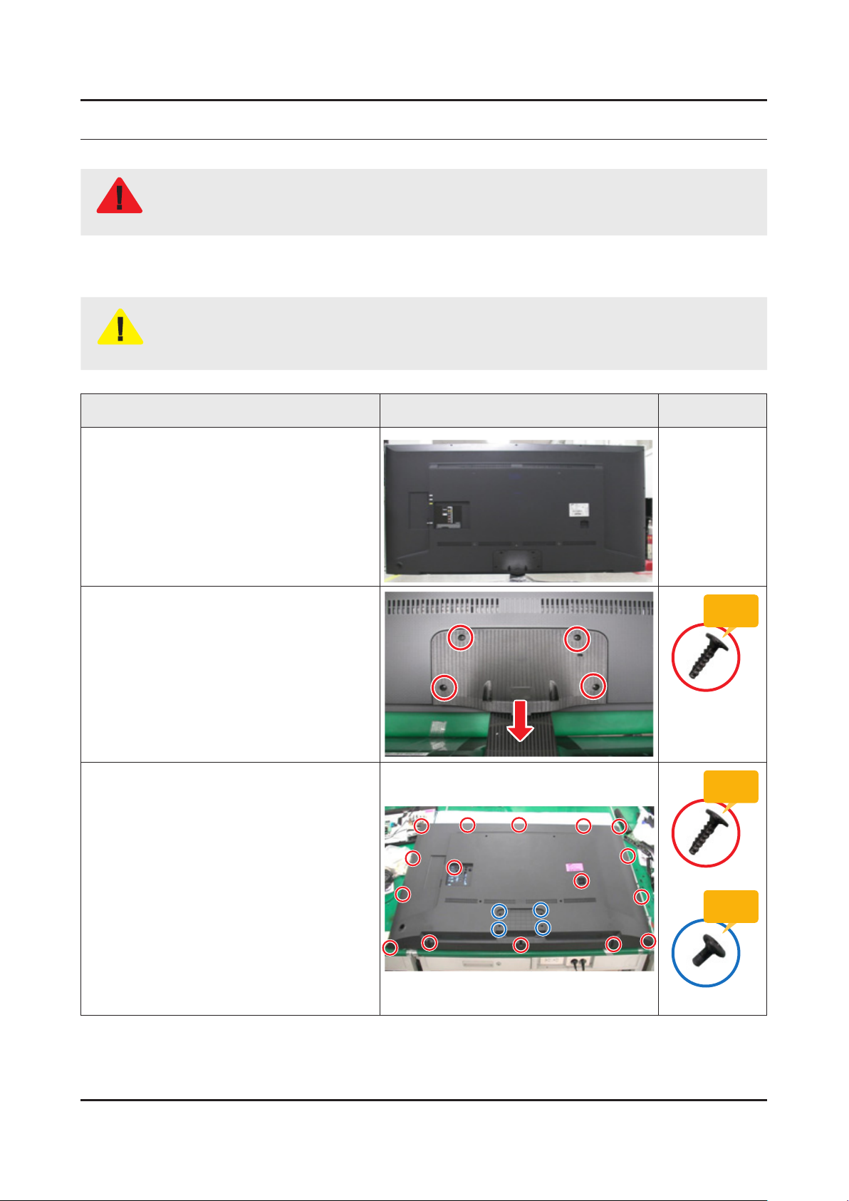
Place TV face down on cushioned table.
If there is no additional coment, it is same for all inches.3.
Description Picture Description Screws
1
Remove screws from the Stand and
2
Remove Stand.
58" : 4ea -
Remove screws of Rear Cover.
3
58" : 16ea, 4ea -
Torque :
9~ 10Kgf.cm
6003-001782
Torque :
9~ 10Kgf.cm
6003-001782
Torque :
7~ 8Kgf.cm
6003-002755
3-1
Page 6
3-2
3. Disassembly and Reassemble
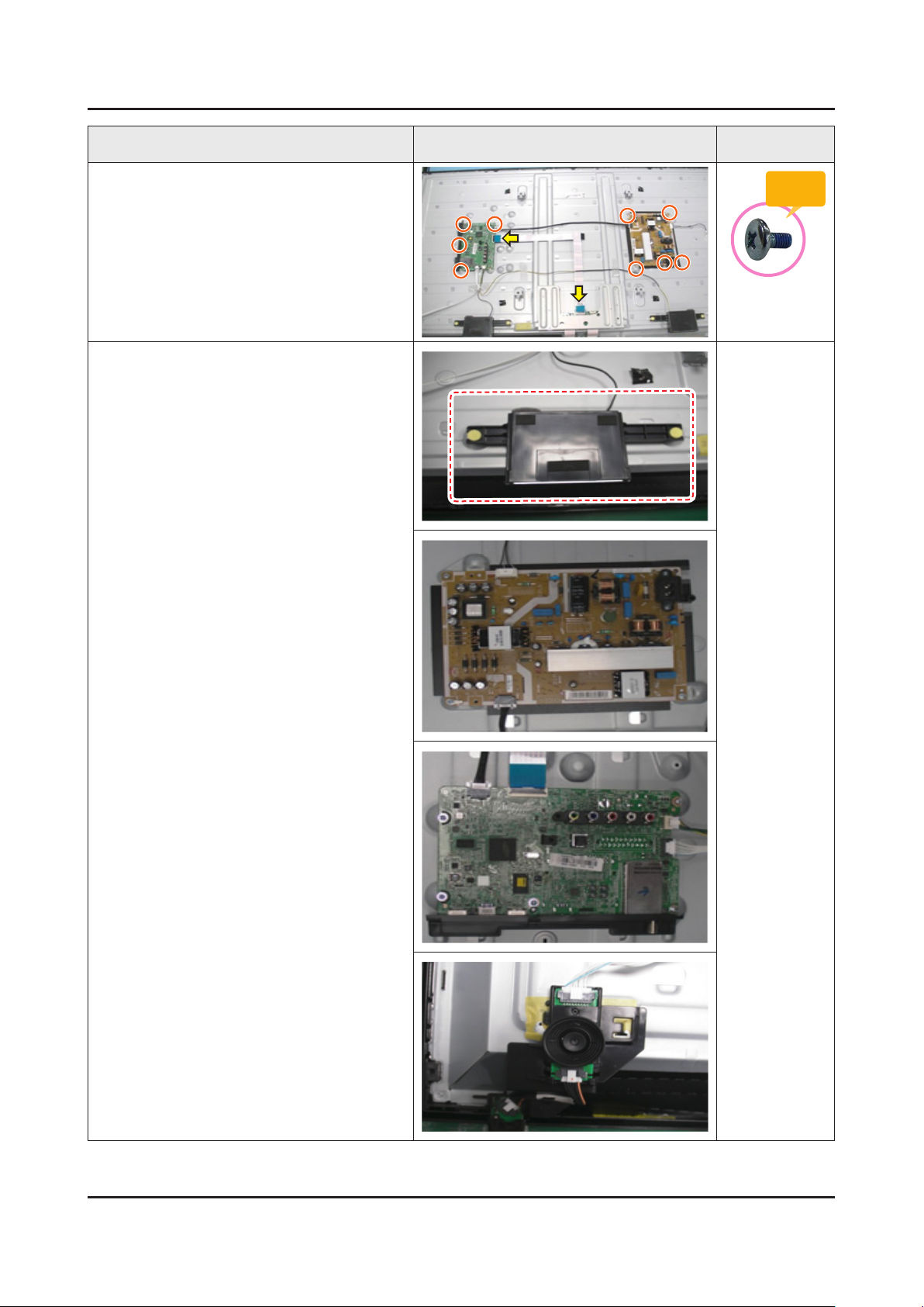
Description Picture Description Screws
Remove 9 screws of Main Board and
4
Power Board.
Remove the Speakers, Power Cables, the
5
LVDS Cable, and the Function.
Torque :
7~ 8Kgf.cm
6001-003016
Page 7

3-3
3. Disassembly and Reassemble
Description Picture Description Screws
Completed disassembly.
6
NOTE
Reassembly procedures are in the reverse order of disassembly procedures.
Page 8
ANNEX. Exploded View & Part List
ANNEX. Exploded View & Part List [UE58J5200AWXXH IS01]
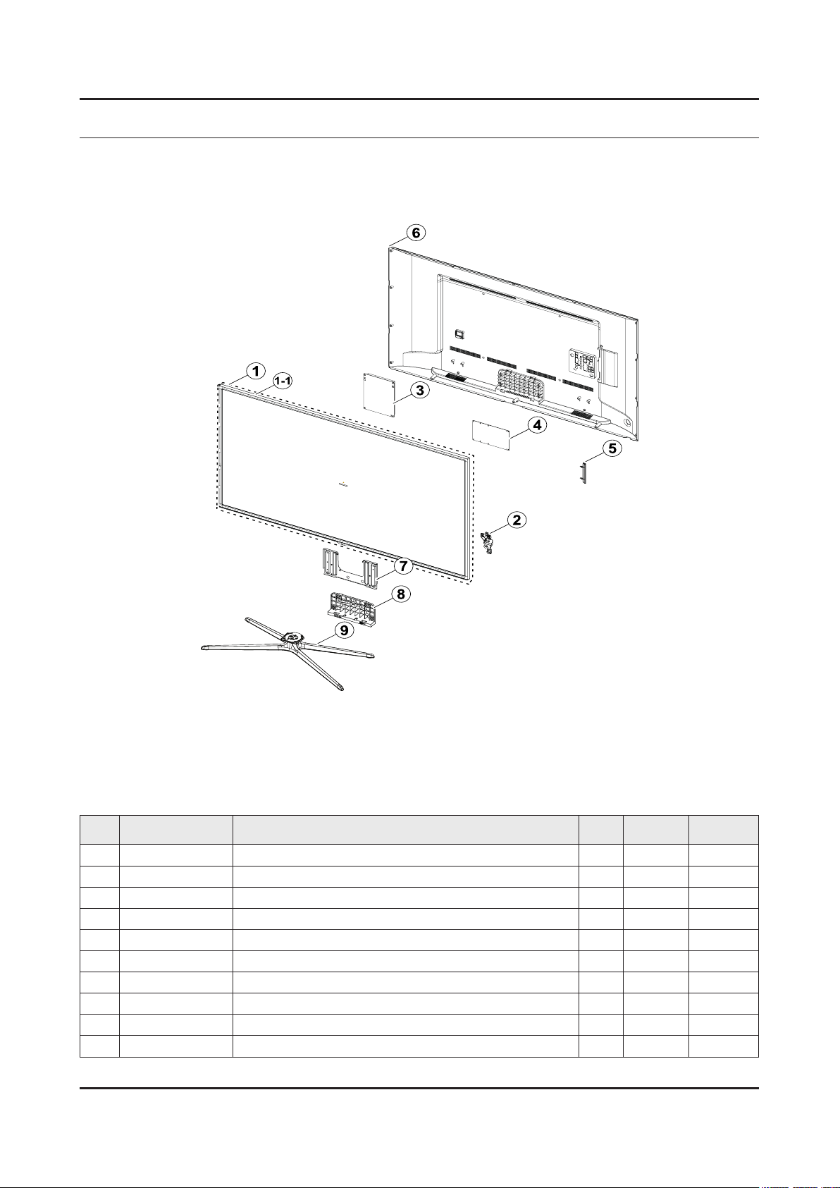
1-1. Exploded View
1-1-1. Parts List
No. Code No. Description & Specication Q’ty SA/SNA Remark
1 BN95-01724A PRODUCT LCD-INX; v580HJ1,CY-HH058BGNV1H/V 1 SA
1-1 BN96-33358A ASSY CHASSIS TOP P; Y14 F-LED 58,PC+ABS+G 1 SA
2 BN96-30902V ASSY BOARD P-FUNCTION; UH5200,Function As 1 SA
3 BN44-00787A DC VSS-PD BOARD; L58GFB_ESM,AC/DC,166W,10 1 SA
4 BN94-10476C ASSY PCB MAIN; LED TV 1 SA
5 BN61-11154A COVER-TERMINAL SIDE; HIPS,BLACK,HB,BLACK, 1 SNA
6 BN96-34022B ASSY COVER P-REAR; H5200 58",MASTER,PC+AB 1 SA
7 BN61-07962B BRACKET-STNAD LINK; UE6030 55",SECC,T1.6, 1 SA
8 BN96-33524A ASSY GUIDE P-STAND; UH5200 58,PC+G/F20%,B 1 SA
9 BN96-30031E ASSY STAND P-BASE; UF6K 60,ABS+PC,BLACK 1 SA
ANNEX-1
Page 9

ANNEX-2
ANNEX. Exploded View & Part List
2-1. Electrical Parts List
Service Bom (SA: SERVICE AVAILABLE, SNA: SERVICE NOT AVAILABLE)
Level Location No. Code No. Description & Specication Q’ty SA/SNA Remark
UE58J5200AWXXH (IS01)
1 R001A BN90-06169D ASSY COVER REAR;UH5203 58" 1 SNA
0.2 SCREW 6001-003074 SCREW-MACHINE;BH,+,M3,L6,ZPC(BLK),SWRCH1 4 SA
0.2 SCREW 6003-001782 SCREW-TAPTYPE;BH,+,B,M4,L12,ZPC(BLK),SWR 16 SA
0.2 R001A BN96-34022B ASSY COVER P-REAR;H5200 58",MASTER,PC+AB 1 SA
..3 R001 BN63-12619P COVER-REAR;H5203, 58",ABS+PC,V0,BLK,MAST 1 SNA
...4 0103-010488 RESIN PC ABS;NH-1055 K21441,Black,BK0008 3750 SNA
..3 T0071 BN64-02773A INLAY-TERMINAL;H6203,PS,T0.4,W165.4,L147 1 SNA
..3 BN68-06629A INLAY-TERMINAL SIDE;H5203,PET,T0.125 1 SNA
1 BN90-07095Q ASSY W/I;J6K 1 SNA
0.2 BN81-08159Z PART SET-ELEC W/I;UF**,UH**,UG**,ELEC 1 SNA
0.2 BN81-11282N A/S PART SET-MECH W/I;UJ5C,U58HF* 1 SNA
1 S001A BN90-07340H ASSY STAND;J5200/J5000 1 SNA
0.2 SB04A BN96-30031E ASSY STAND P-BASE;UF6K 60,ABS+PC,BLACK 1 SA
..3 SCREW 6002-001294 SCREW-TAPPING;BH,+,,M4,L16,ZPC(BLK) 4 SA
..3 SCREW 6003-001425 SCREW-TAPTYPE;BH,+,B,M4,L25,ZPC(BLK),SWR 4 SNA
..3 SCREW 6003-001785 SCREW-TAPTYPE;FH,+,B,M4,L8,ZPC(BLK),SWRC 4 SA
..3 SCREW 6003-001832 SCREW-TAPTYPE;FH,+,B,M4,L30,ZPC(BLK),SWR 1 SNA
..3 BN61-07165B HOLDER-STAND SWIVEL;60" QUAD STAND,ACETA 1 SNA
..3 BN61-08737A HOLDER-STAND SWIVEL;46-55 SLIM QUAD STAN 1 SNA
...4 0103-009825 RESIN POM;TS-25A,Dark Gray,GY0199,HB 6 SNA
..3 SG01 BN61-08738A GUIDE-STAND NECK;46-55 SLIM QUAD STAND,P 1 SNA
..3 BN61-08739A BRACKET-STAND,TOP;46-55 SLIM QUAD STAND, 1 SNA
..3 BN61-08740A BRACKET-STAND,BOTTOM;46-55 SLIM QUAD STA 1 SNA
..3 BN61-09955A BRACKET-STAND SWIVEL;UF6400 60 QUAD,SPCC 1 SNA
..3 BN61-09957A BRACKET-STAND SWIVEL;UF6400 60 QUAD,SPCC 1 SNA
...4 BN61-02428Q STUD-PEM;M4,D7,L9.3,PNA,ZPC(SIL),SUM24L 4 SNA
..3 AS080 BN63-05135E SHEET-COVER;4-LEG,PE,T0.05,W60mm,Cr-plat 2 SNA
..3 BN63-10161A COVER-STAND TOP;46-55 SLIM QUAD STAND,AB 1 SNA
..3 BN63-10199A COVER-STAND TOP;46-55 SLIM QUAD STAND,AB 1 SNA
...4 0103-005041 RESIN PC ABS;FR3200TV,901408,BK0008,1.2m 180 SNA
..3 RF01 BN67-00385D FOOT-RUBBER;GRAY,T2 4 SNA
0.2 SG01A BN96-33524A ASSY GUIDE P-STAND;UH5200 58,PC+G/F20%,B 1 SA
..3 SG03 BN61-10894A GUIDE-STAND;UH5200 58",PC+GF20%,BK0007,V 1 SNA
...4 0103-007285 RESIN PC;HF3200H,K21294,BK0007,V2 1.5mm 300
...4 BN68-00513D LABEL-RESIN;resin,ART,10,25 1 SNA
..3 BN68-05603A LABEL-E,PASS;ALL MODEL,ART PAPER 90G,60, 1 SNA
..3 BN69-08751A WRAP VINYL-SHRINK;STAND,PLASTIC OTHERS,P 0 SNA
..3 BN96-29120C ASSY ACCESSORY-SCREW;6003-001782,8EA,LED 1 SNA
...4 SCREW 6003-001782 SCREW-TAPTYPE;BH,+,B,M4,L12,ZPC(BLK),SWR 8 SA
...4 BN69-09241C BAG SCREW;LDPE,0.05,70,90,TRP,Vinyl pack 1 SNA
1 BN91-12976A ASSY LCM-AMLCD;BN95-01724A,CY-HH058BGNV1 1 SNA
0.2 PANEL BN95-01724A PRODUCT LCD-INX;v580HJ1,CY-HH058BGNV1H/V 1 SA
..3 SCREW 6001-003075 SCREW-MACHINE;BH,+,M3,L4,ZPC(WHT),SWRCH1 6 SA
Page 10

ANNEX-3
ANNEX. Exploded View & Part List
Level Location No. Code No. Description & Specication Q’ty SA/SNA Remark
..3 BN61-07962B BRACKET-STNAD LINK;UE6030 55",SECC,T1.6, 1 SA
..3 M0131 BN63-00520A GASKET;APPOLO_PAL,Conductive Fabric,0.13 8 SNA
..3 BN68-05722A LABEL-STICKER;ALL MODEL,POLYPROPYLENE,0. 1 SNA
..3 BN90-05987A ASSY MISC-BLU;MEGA MODEL,CY-HH058BGNV1V 1 SNA
...4 BN02-00102B TAPE-FILAMENT;#8917,0.15,25,50,WHITE 3 SNA
...4 BN02-00152E TAPE ETC-SHEET FIXING;Y13 SF-LED,PET,0.0 4 SNA
...4 BN61-07891A SUPPORT-PLATE;Y12 FULL LED,PC,V2,CLEAR 9 SNA
...4 BN61-10791A LGP-DIFFUSESR PLATE;58inch Mega, Diffuse 1 SNA
...4 BN62-00635A INSULATOR-SOURCE PCB RIGHT;PC,VTM,NATURA 1 SNA
...4 BN62-00635B INSULATOR-SOURCE PCB LEFT;PC,VTM,BLACK,L 1 SNA
...4 BN63-12638A OPTICAL SHEET-COMPLEX;14Y_H5K 58inch_G23 1 SNA
...4 BN63-12640A OPTICAL SHEET-REFLECTOR;14Y_H5K 58inch_U 1 SNA
...4 BN96-32771A ASSY LED BAR P;58inch Left,Direct LED PK 6 SNA
...4 BN96-32772A ASSY LED BAR P;58inch Right,Direct LED P 6 SNA
...4 BN96-33354A ASSY CHASSIS BOTTOM P;Y14 F-LED 58,MEGA, 1 SNA
....5 AK63-00675A GASKET;BD-C7500,Conductive Fabric,2mm,5m 4 SNA
....5 BN02-00040C TAPE DOUBLE FACE-D-PLATE;F-LED ALL,MKT50 2 SNA
....5 BN02-00074D TAPE PET;58H5200,PET,T0.05,W40,L40,BLK,3 4 SNA
....5 BN02-00102B TAPE-FILAMENT;#8917,0.15,25,50,WHITE 1 SNA
....5 BN02-00134E TAPE PET;SFLED 32/40/46/55/61,3M 3357 FR 6 SNA
....5 BN02-00324A TAPE-METAL FOIL;Y14 4K,T0.085,W25,NTR,3M 0 SNA
....5 EC13 BN39-01910A LEAD CONNECTOR;58inch Mega,Lead Connecto 1 SNA
....5 BN61-11027A HOLDER-SOURCE PCB;H4.2K 58",NYLON66,1.8T 4 SNA
....5 BN62-00501M INSULATOR-SMPS;PC,BLACK,L180,W240,T0.43 1 SNA
....5 CC02 BN64-02743A CHASSIS-BOTTOM;Y14 F-LED 58",EGI-SECC AG 1 SNA
.....6 BN01-00231A STEEL;EGI-SECC AG,1365,0.8mm,815mm,SECC, 1 SNA
....5 BN74-00053J TAPE-PAPER;PAPER,3M2307,T0.14,W25,ROLL,W 1 SNA
...4 BN96-33355A ASSY FRAME P-MOLD MIDDLE U;Y14 F-LED 58, 1 SNA
....5 BN61-10803A FRAME-MOLD MIDDLE U;Y14 F-LED 58",PC+G/F 1 SNA
...4 BN96-33356A ASSY FRAME P-MOLD MIDDLE D;Y14 F-LED 58, 1 SNA
....5 BN60-00744A SPACER-RUBBER;Y13 F-LED SLIM,SH-0140U+AT 1 SNA
....5 BN60-00999E SPACER-PANEL(UD);14 ENTRY MODEL 58",SI,6 2 SNA
....5 BN61-10804A FRAME-MOLD MIDDLE D;Y14 F-LED 58",PC+G/F 1 SNA
...4 BN96-33357A ASSY FRAME P-MOLD MIDDLE LR;Y14 F-LED 58 2 SNA
....5 BN60-00999F SPACER-PANEL(LR);14 ENTRY MODEL 58" & quot 2 SNA
....5 BN61-10805A FRAME-MOLD MIDDLE LR;Y14 F-LED 58",PC+G/ 2 SNA
..3 FL06 BN96-30782D ASSY CABLE P-FFC;H7000,FFC,NH,68mm짹1,60 2 SNA
..3 BN96-32743A ASSY OPEN CELL;V580HJ1-PD6,CY-HH058BGNV1 1 SNA
...4 BN81-10743A A/S-A/S-IC DRIVER SOURCE;INX 58 FHD 60Hz 1 SNA
...4 BN81-10744A A/S-A/S-IC DRIVER GATE;INX 58 FHD 60Hz,6 1 SNA
...4 BN81-10745A A/S-A/S-ASSY PCB-SOURCE (XR);INX 58 FHD 1 SNA
...4 BN81-10746A A/S-A/S-ASSY PCB-SOURCE (XL);INX 58 FHD 1 SNA
...4 BN81-10747A A/S-A/S-POLARIZER-C/F;INX 58 FHD 60Hz,41 1 SNA
...4 BN81-10748A A/S-A/S-POLARIZER-TFT;INX 58 FHD 60Hz,41 1 SNA
..3 TCON BN96-32745A ASSY T CON P;V580HJ1-PE6,V580HJ1-PE6,10b 1 SA
..3 TC01A BN96-33358A ASSY CHASSIS TOP P;Y14 F-LED 58,PC+ABS+G 1 SA
...4 BN60-00667K SPACER-GASKET;Y13 SF-LED,CONDUCTIVE FABR 3 SNA
Page 11

ANNEX-4
ANNEX. Exploded View & Part List
Level Location No. Code No. Description & Specication Q’ty SA/SNA Remark
...4 BN60-00930Z SPACER-TOP(UD);Y14 VNB 58",PET,L1280,GOL 2 SNA
...4 BN60-01010A SPACER-CORNER;H4203,CONDUCTIVE FABRIC,9m 4 SNA
...4 BN60-01071A SPACER-TOP(LR);Y14 VNB 58",PET,L727,GOLD 2 SNA
...4 BN63-11875Q SHEET-COVER;Y14 SF-LED,POLY*,0.068,W37,R 1 SNA
...4 BN63-11875S SHEET-COVER;Y14 SF-LED,POLYESTER,0.068,W 3 SNA
...4 AC157 BN64-02744A CHASSIS-TOP;Y14 F-LED 58",PC+ABS+G/F15%, 1 SNA
1 BN91-13443B ASSY SHIELD;UH5200 58" 1 SNA
0.2 SCREW 6001-003081 SCREW-MACHINE;PWH,+,M3,L5,ZPC(WHT),SWRCH 13 SA
0.2 BN02-00102B TAPE-FILAMENT;#8917,0.15,25,50,WHITE 0 SNA
0.2 EC13 BN39-01765A LEAD CONNECTOR;UE46F5300,Flat Connector 1 SA
0.2 EC13 BN39-01889K LEAD CONNECTOR;UE50H6300,Flat Connector, 1 SA
0.2 P001A BN44-00787A DC VSS-PD BOARD;L58GFB_ESM,AC/DC,166W,10 1 SA
0.2 CB20 BN61-07953A BRACKET-WALL;UE5000 46",EGI-SECC PL,T1.2 4 SA
0.2 M0131 BN63-00520A GASKET;APPOLO_PAL,Conductive Fabric,0.13 1 SNA
0.2 FB01A BN96-30902V ASSY BOARD P-FUNCTION;UH5200,Function As 1 SA
0.2 SPK BN96-32113E ASSY SPEAKER P-H5203 58";6ohm,10W,H5203 1 SA
0.2 FL06 BN96-33236H ASSY CABLE P-FFC;58H5203,FFC,NH,500mm,51 1 SA
1 M0017 BN91-16918M ASSY CHASSIS;LED TV 1 SNA
0.2 M0014 BN94-10476C ASSY PCB MAIN;LED TV 1 SA
..3 BN61-11154A COVER-TERMINAL SIDE;HIPS,BLACK,HB,BLACK, 1 SNA
...4 0103-004628 RESIN HIPS;HF-1690H,K2901,BK0020,1.5mm H 13 SNA
..3 BN62-00637A INSULATOR-SHEET;PET,BLACK,L10,W10,T0.1 1 SNA
..3 AH020 BN62-00659A HEAT SINK;UN55H6203AFXZA,A6063,BLACK 1 SNA
..3 BN62-00670A INSULATOR-SHEET;PET,BLACK,L54,W54,T0.43 1 SNA
..3 BN63-10091A GASKET;SB750H,PUR FOAM,10mm,10mm,5mm,Gra 2 SNA
..3 BN97-08893Y ASSY SMD;UH5F 1 SNA
...4 0202-001899 SOLDER-CREAM;M705-GRN360-K2-VT,20-38um,S 3 SNA
...4 DS01A 0401-001056 DIODE-SWITCHING;MMBD4148SE,100,200,SOT-2 1 SA
...4 0403-001783 DIODE-ZENER;BZB84-C6V2,5.8~6.6V,300,SOT- 4 SNA
...4 0404-001404 DIODE-SCHOTTKY;BAT721C,40,200,SOT-23,TP 2 SA
...4 0406-001200 DIODE-TVS;RClamp0504F,6,0,0,1,0,0,TP 2 SA
...4 0406-001628 DIODE-TVS;AOZ8804ADI,6,0,0,1,1,5,TP 1 SA
...4 0406-001635 DIODE-TVS;SMF5.0A,6.4,6.7,7,200,0,20,TP 5 SA
...4 0501-000279 TR-SMALL SIGNAL;KSA1182-Y,PNP,150,SOT-23 3 SA
...4 0501-000445 TR-SMALL SIGNAL;KTC3875S-Y,NPN,150,SOT-2 4 SC
...4 0505-002560 FET-SILICON;AO6415,P,20V,-3.3A,0.15mohm, 1 SA
...4 0505-002598 FET-SILICON;AP2317GN,P,20V,-4.2A,0.052mo 1 SA
...4 0505-002893 FET-SILICON;AO4801AS,P,30V,-5A,2,SOIC-8 1 SA
...4 0505-003397 FET-SILICON;2N7002K,N,60V,0.38A,1.19mohm 5 SA
...4 0801-002780 IC-CMOS LOGIC;74LVC1G17,SCHMITT-TRIGGER 2 SA
...4 0801-003330 IC-CMOS LOGIC;Octal buffer,DQFN,20P,4.5x 1 SA
...4 1001-001860 IC-ANALOG SWITCH;NX5L2750CGU,QFN,10P,1.4 1 SNA
...4 1103-001487 IC-EEPROM;AT24C256C-SSHL-T,256Kbit,32Kx8 1 SA
...4 1105-002527 IC-DDR3 SDRAM;K4B2G1646Q-BCK0,DDR3,2Gbit 1 SA
...4 1105-002529 IC-DDR3 SDRAM;K4B4G1646D-BCK0,DDR3 1600, 1 SA
...4 1201-003183 IC-AUDIO AMP;DRV612,HTSSOP,14P,5x4.4mm,D 1 SA
...4 1201-003690 IC-AUDIO AMP;TAS5747PHPR,QFP,48P,DUAL,PL 1 SA
Page 12

ANNEX-5
ANNEX. Exploded View & Part List
Level Location No. Code No. Description & Specication Q’ty SA/SNA Remark
...4 1203-004363 IC-VOL. DETECTOR;SOT-23,3Z30,2.9x1.6mm,P 1 SA
...4 1203-006017 IC-VOL. DETECTOR;RT9824GJ8,TSOT23,8P,2.9 1 SA
...4 1203-006130 IC-POSI.FIXED REG.;S-1172B25-U5T1G,SOT-8 1 SA
...4 1203-007238 IC-PWM CONTROLLER;TPS54427,DDA,8P,4.8x3. 1 SNA
...4 1203-007242 IC-POSI.ADJUST REG.;G2992BP11U,SOP-8,8P, 1 SA
...4 1203-008104 IC-POSI.FIXED REG.;S-13A1D18-E800,HSOP,8 2 SNA
...4 1203-008105 IC-POSI.FIXED REG.;S-13A1D33-E800,HSOP,8 1 SNA
...4 1203-008118 IC-DC/DC CONVERTER;AOZ3013PI,SO-8,8P,4.9 3 SA
...4 1203-008183 IC-DC/DC CONVERTER;AOZ3015PI-1,EPAD SO-8 1 SA
...4 1204-003558 IC-VIDEO PROCESS;SENK15,HS-TFBGA,626P,26 1 SA
...4 1205-004447 IC-SWITCH;TPS2051CDBVR,SOT23-5,5P,3x1.65 2 SA
...4 1205-004983 IC-SWITCH;BD82032FVJ,TSSOP-B8J,8P,3.0x4. 1 SA
...4 1405-001271 VARISTOR;35V,20Vdc,5A,1.0x0.5mm,TP,100V, 25 SA
...4 2007-000138 R-CHIP;100ohm,5%,1/16W,TP,1005 28 SA
...4 2007-000140 R-CHIP;1Kohm,5%,1/16W,TP,1005 9 SNA
...4 2007-000141 R-CHIP;2.2Kohm,5%,1/16W,TP,1005 6 SNA
...4 2007-000142 R-CHIP;2.7Kohm,5%,1/16W,TP,1005 1 SNA
...4 2007-000143 R-CHIP;4.7Kohm,5%,1/16W,TP,1005 25 SNA
...4 2007-000148 R-CHIP;10Kohm,5%,1/16W,TP,1005 24 SA
...4 2007-000153 R-CHIP;22Kohm,5%,1/16W,TP,1005 8 SNA
...4 2007-000157 R-CHIP;47Kohm,5%,1/16W,TP,1005 15 SNA
...4 2007-000162 R-CHIP;100Kohm,5%,1/16W,TP,1005 1 SNA
...4 2007-000171 R-CHIP;0ohm,5%,1/16W,TP,1005 10 SNA
...4 2007-000172 R-CHIP;10ohm,5%,1/16W,TP,1005 3 SNA
...4 2007-000173 R-CHIP;22ohm,5%,1/16W,TP,1005 21 SNA
...4 2007-000174 R-CHIP;47ohm,5%,1/16W,TP,1005 2 SNA
...4 2007-000256 R-CHIP;1.6Kohm,1%,1/10W,TP,1608 3 SA
...4 2007-000265 R-CHIP;1.8Kohm,1%,1/10W,TP,1608 1 SA
...4 2007-000583 R-CHIP;22Kohm,1%,1/10W,TP,1608 3 SA
...4 2007-000691 R-CHIP;3.3Mohm,5%,1/10W,TP,1608 1 SA
...4 2007-000726 R-CHIP;300ohm,1%,1/10W,TP,1608 2 SA
...4 2007-000775 R-CHIP;33Kohm,5%,1/16W,TP,1005 2 SNA
...4 2007-000803 R-CHIP;36Kohm,1%,1/10W,TP,1608 2 SA
...4 2007-000932 R-CHIP;470ohm,5%,1/16W,TP,1005 8 SNA
...4 2007-001125 R-CHIP;68Kohm,1%,1/10W,TP,1608 1 SA
...4 2007-001168 R-CHIP;75ohm,5%,1/4W,TP,3216 1 SA
...4 2007-001288 R-CHIP;18ohm,5%,1/16W,TP,1005 4 SA
...4 2007-001292 R-CHIP;33ohm,5%,1/16W,TP,1005 2 SNA
...4 2007-001298 R-CHIP;51ohm,5%,1/16W,TP,1005 2 SNA
...4 2007-002970 R-CHIP;56ohm,5%,1/16W,TP,1005 2 SA
...4 2007-003015 R-CHIP;2.2ohm,5%,1/16W,TP,1005 8 SNA
...4 2007-003022 R-CHIP;62ohm,5%,1/16W,TP,1005 26 SNA
...4 2007-007001 R-CHIP;3.9Kohm,5%,1/16W,TP,1005 1 SA
...4 2007-007095 R-CHIP;390ohm,5%,1/16W,TP,1005 1 SA
...4 2007-007107 R-CHIP;100Kohm,1%,1/16W,TP,1005 6 SNA
...4 2007-007136 R-CHIP;4.7Kohm,1%,1/16W,TP,1005 18 SNA
...4 2007-007142 R-CHIP;10Kohm,1%,1/16W,TP,1005 20 SNA
Page 13

ANNEX-6
ANNEX. Exploded View & Part List
Level Location No. Code No. Description & Specication Q’ty SA/SNA Remark
...4 2007-007156 R-CHIP;1ohm,5%,1/16W,TP,1005 2 SNA
...4 2007-007306 R-CHIP;100ohm,1%,1/16W,TP,1005 6 SNA
...4 2007-007309 R-CHIP;12Kohm,1%,1/16W,TP,1005,0.35T 3 SA
...4 2007-007311 R-CHIP;22Kohm,1%,1/16W,TP,1005 1 SA
...4 2007-007312 R-CHIP;30Kohm,1,1/16W,TP,1005 1 SA
...4 2007-007318 R-CHIP;1Kohm,1%,1/16W,TP,1005 16 SNA
...4 2007-007470 R-CHIP;7.5Kohm,1%,1/16W,TP,1005 1 SNA
...4 2007-007517 R-CHIP;240ohm,1%,1/16W,TP,1005 2 SNA
...4 2007-007538 R-CHIP;56Kohm,1%,1/16W,TP,1005 1 SA
...4 2007-007766 R-CHIP;2Kohm,1%,1/16W,TP,1005 1 SNA
...4 2007-007942 R-CHIP;1Mohm,1%,1/16W,TP,1005 1 SNA
...4 2007-008015 R-CHIP;75ohm,1%,1/16W,TP,1005 19 SNA
...4 2007-008117 R-CHIP;2.7Kohm,1%,1/16W,TP,1005 1 SA
...4 2007-008275 R-CHIP;30Kohm,1%,1/16W,TP,1005 2 SNA
...4 2007-008294 R-CHIP;33ohm,1%,1/16W,TP,1005 5 SA
...4 2007-008298 R-CHIP;49.9ohm,1%,1/16W,TP,1005 4 SA
...4 2007-008332 R-CHIP;11.5Kohm,1%,1/16W,TP,1005 1 SA
...4 2007-008473 R-CHIP;59Kohm,1%,1/10W,TP,1608 1 SA
...4 2007-008779 R-CHIP;0ohm,1%,1/16W,TP,1005 4 SA
...4 2011-001261 R-NETWORK;33ohm,5%,1/16W,L,CHIP,8P,TP,2. 2 SA
...4 2011-001262 R-NETWORK;22ohm,5%,1/16W,L,CHIP,8P,TP,2. 1 SA
...4 2011-001344 R-NETWORK;100ohm,5%,1/16W,L,CHIP,8P,TP,2 2 SA
...4 2011-001402 R-NETWORK;56ohm,5%,1/16W,L,CHIP,8P,TP,2. 8 SA
...4 2011-001449 R-NETWORK;22ohm,5%,1/16W,L,4Points,TP,10 3 SA
...4 2011-001506 R-NETWORK;10Kohm,5%,1/16W,L,CHIP,4P,TP,1 4 SNA
...4 2011-001527 R-NETWORK;4.7Kohm,5%,1/16W,L,CHIP,4P,TP, 3 SNA
...4 2011-001587 R-NETWORK;100ohm,5%,1/16W,L,CHIP-V,4P,TP 1 SNA
...4 AD480 2203-000233 C-CER,CHIP;0.1nF,5%,50V,C0G,TP,1005 8 SA
...4 AD480 2203-000278 C-CER,CHIP;0.01nF,0.5pF,50V,C0G,TP,1005 3 SA
...4 AD480 2203-000330 C-CER,CHIP;0.012nF,5%,50V,C0G,TP,1005 2 SA
...4 AD480 2203-000359 C-CER,CHIP;0.15nF,5%,50V,C0G,TP,1005,0.5 1 SNA
...4 AD480 2203-000438 C-CER,CHIP;1nF,10%,50V,X7R,TP,1005 16 SA
...4 AD480 2203-000489 C-CER,CHIP;2.2nF,10%,50V,X7R,TP,1005 4 SA
...4 AD480 2203-000575 C-CER,CHIP;220nF,10%,25V,X7R,TP,2012 6 SNA
...4 AD480 2203-000585 C-CER,CHIP;0.22nF,10%,50V,X7R,TP,1005 1 SA
...4 AD480 2203-000627 C-CER,CHIP;0.022nF,5%,50V,C0G,TP,1005 3 SNA
...4 AD480 2203-000679 C-CER,CHIP;0.027nF,5%,50V,C0G,TP,1005 2 SA
...4 AD480 2203-000714 C-CER,CHIP;3.3nF,10%,50V,X7R,TP,1005 7 SA
...4 AD480 2203-000812 C-CER,CHIP;0.033nF,5%,50V,C0G,TP,1005 5 SA
...4 AD480 2203-000940 C-CER,CHIP;0.47nF,10%,50V,X7R,TP,1005 4 SA
...4 AD480 2203-002285 C-CER,CHIP;10nF,10%,50V,X7R,TP,1005 19 SNA
...4 AD480 2203-002711 C-CER,CHIP;100nF,10%,25V,X7R,TP,1608 6 SA
...4 AD480 2203-005249 C-CER,CHIP;100nF,10%,50V,X7R,TP,1608 6 SNA
...4 AD480 2203-005344 C-CER,CHIP;22nF,10%,25V,X7R,TP,1005,0.5T 1 SNA
...4 AD480 2203-005659 C-CER,CHIP;0.18nF,5%,50V,NP0,TP,1005 1 SNA
...4 AD480 2203-005968 C-CER,CHIP;4.7nF,10%,50V,X7R,TP,1005,0.5 3 SNA
...4 AD480 2203-006048 C-CER,CHIP;100nF,10%,10V,X7R,TP,1005 103 SA
Page 14

ANNEX-7
ANNEX. Exploded View & Part List
Level Location No. Code No. Description & Specication Q’ty SA/SNA Remark
...4 AD480 2203-006126 C-CER,CHIP;47nF,10%,16V,X7R,TP,1005 17 SNA
...4 AD480 2203-006158 C-CER,CHIP;100nF,10%,16V,X7R,TP,1005,0.5 20 SNA
...4 AD480 2203-006324 C-CER,CHIP;2200nF,10%,10V,X5R,TP,1608 7 SA
...4 AD480 2203-006348 C-CER,CHIP;1000nF,10%,25V,X5R,TP,1608,0. 2 SA
...4 AD480 2203-006361 C-CER,CHIP;10000nF,10%,10V,X5R,TP,2012 21 SC
...4 AD480 2203-006399 C-CER,CHIP;1000nF,10%,6.3V,X5R,TP,1005 1 SA
...4 AD480 2203-006474 C-CER,CHIP;22000nF,20%,6.3V,X5R,TP,2012 34 SA
...4 AD480 2203-006562 C-CER,CHIP;1000nF,10%,10V,X5R,TP,1005 18 SNA
...4 AD480 2203-006824 C-CER,CHIP;4700nF,10%,10V,X5R,TP,1608 5 SNA
...4 AD480 2203-006838 C-CER,CHIP;2200nF,10%,6.3V,X5R,TP,1005 1 SA
...4 AD480 2203-006841 C-CER,CHIP;1000nF,10%,16V,X5R,TP,1005 4 SNA
...4 AD480 2203-006842 C-CER,CHIP;0.47nF,5%,50V,C0G,TP,1005 2 SNA
...4 AD480 2203-006890 C-CER,CHIP;10000nF,20%,6.3V,X5R,TP,1608 27 SNA
...4 AD480 2203-006992 C-CER,CHIP;0.33nF,5%,50V,C0G,TP,1005 8 SNA
...4 AD480 2203-007176 C-CER,CHIP;10000nF,10%,16V,X5R,TP,2012,1 5 SNA
...4 AD480 2203-007269 C-CER,CHIP;22000nF,20%,10V,X5R,TP,2012(2 8 SA
...4 AD480 2203-007270 C-CER,CHIP;10000nF,10%,10V,X5R,TP,1608,0 4 SNA
...4 AD480 2203-007513 C-CER,CHIP;10000nF,10%,10V,X5R,TP,1608,0 2 SA
...4 AD480 2203-007544 C-CER,CHIP;100nF,10%,50V,X7R,TP,1005,0.5 9 SA
...4 2409-001213 C-ORGANIC,SMD;150uF,20%,6.3V,-,TP,3.5x2. 2 SNA
...4 2703-000158 INDUCTOR-SMD;1uH,10%,2012,.4Ohm,50mA,45, 4 SA
...4 2703-000213 INDUCTOR-SMD;470nH,10%,1608,1.35Ohm,35mA 1 SA
...4 2703-001209 INDUCTOR-SMD;1.2uH,10%,1608,.8Ohm,25mA,3 3 SA
...4 2703-001938 INDUCTOR-SMD;56nH,5%,1005,1.5Ohm,200mA,1 2 SA
...4 2703-002332 INDUCTOR-SMD;330nH,5%,1608,3Ohm,100mA,32 1 SA
...4 2703-003713 INDUCTOR-SMD;1.5uH,20%,7366,0.015ohm,700 2 SA
...4 2703-003790 INDUCTOR-SMD;4.7uH,20%,8080,0.025ohm,450 2 SA
...4 2703-003930 INDUCTOR-SMD;4.7uH,20%,0.072Ohm,2450mA,W 4 SA
...4 2703-004462 INDUCTOR-SMD;3.3uH,20%,10x10x8mm,0.0082O 1 SA
...4 2801-003773 CRYSTAL-SMD;12MHz,30ppm,28-AAN,20pF,50oh 1 SA
...4 3301-000314 BEAD-SMD;120ohm,1608,TP,120ohm/100MHz 6 SNA
...4 3301-001364 BEAD-SMD;1000ohm,1608,TP,1085ohm/108MHz, 2 SNA
...4 3301-002039 BEAD-SMD;26ohm,1608,TP 37 SA
...4 3601-001374 FUSE-SURFACE MOUNT;32V,5A,FAST-ACTING,PL 2 SA
...4 3701-001856 CONNECTOR-HDMI;19P,FEMALE,AU,0.5mm,BLK,S 2 SA
...4 3707-001106 CONNECTOR-OPTICAL;STRAIGHT W/L,SPDIF 1 SA
...4 3708-003073 CONNECTOR-FPC/FFC/PIC;51P,0.5mm,SMD,AU,N 1 SA
...4 3709-001712 CONNECTOR-CARD SLOT;68P,1.27mm,ANGLE,AU, 1 SA
...4 EH01 3711-008131 HEADER-BOARD TO CABLE;BOX,4P,1R,2.5mm,AN 1 SA
...4 EH01 3711-008453 HEADER-BOARD TO CABLE;BOX,18P,2R,2mm,ANG 1 SA
...4 EH01 3711-008558 HEADER-BOARD TO CABLE;BOX,26P,2R,1.25mm, 1 SA
...4 3722-003229 JACK-MODULAR;8P/8C W/L,Y,STRAIGHT,N,Au,1 1 SA
...4 3722-003248 JACK-USB;4P/1C(W/L),NI/PD/AU/SN,BLK,STRA 2 SA
...4 JACK PIN 3722-003546 JACK-PIN;5P+Screw hole,NI+SN,G,Y/BLU/RED 1 SA
...4 3722-003655 JACK-SCART;21P,SN,BLK 1 SA
...4 3722-003667 JACK-PHONE;1P/7C,SN/NI,BLK,STRAIGHT,3.6P 2 SA
...4 ET01 BN40-00281A TUNER;DTOS40EIL276A,DTOS40EIL276A,DVB-TC 1 SA
Page 15
ANNEX-8
ANNEX. Exploded View & Part List
Level Location No. Code No. Description & Specication Q’ty SA/SNA Remark
...4 BN41-02272A PCB-MAIN;H5203,FR-4,4,A,1.2,192*158,1 1 SNA
...4 BN97-08451A ASSY MICOM-IRB;GOLF-P,U8FB,MAXQ636V,IC24 1 SNA
....5 BN13-00067A IC-PLD;MAXQ636V-2591+T,9,1.64 to 3.6,-0 1 SNA
...4 BN97-08852A ASSY MICOM-MAIN;T-NT14MDEUC-XXXX,U8MB,KL 1 SNA
....5 1107-002287 IC-EMMC;KLM4G1FEAC-C031,4GByte,BGA,153P, 1 SA
...4 BN97-08853A ASSY MICOM-SUB;SUBMICOM,U8MB,W25Q40CLSSI 1 SNA
....5 1107-002226 IC-NOR FLASH;W25Q40CLSSIP,4Mbit,SOIC,8P, 1 SA
..3 BN97-09495A ASSY DRM-KEY;HU7*,NT14U,EU 1 SNA
...4 BN46-00109H KEY CODE-CERTIFI;MAC,TV/AV,General 1 SNA
...4 BN46-00110P KEY CODE-CERTIFI;MIRACAST(HDCP2.2), TV 1 SNA
...4 BN46-00328B KEY CODE-CERTIFI;CI+,TV,NT14, EU 1 SNA
1 ACCE1 BN92-17405A ASSY ACCESSORY;LED J6K UHD 1 SNA
0.2 BN68-07519B LABEL-ENERGY;EU,Jordan all(A++),WW,PP,0. 1 SNA
0.2 BN96-37428A ASSY ACCESSORY MANUAL;JU6S,EUROPE.CIS 1 SNA
..3 6902-001964 BAG PE;LDPE,BIOBASED,T0.03,W200,L300,TRP 1 SNA
..3 BN68-03548J LEAFLET-WARRANTY;comm,Samsung,17Lang,Mid 1 SNA
..3 BN68-04972E LEAFLET-REGULATORY GUIDE;ALL,SAMSUNG,W/W 1 SNA
..3 BN68-07351G LEAFLET-FICHE;ALL,W/P*,4 1 SNA
..3 BN68-07681D MANUAL USERS;J5200,XH,W/P 1 SNA
0.2 BN96-38700J ASSY ACCESSORY CABLE;UHD LED TV 1 SNA
..3 T0268 3903-000950 CBF-POWER CORD;DT,CEE,LP-21L,250V,2.5A,B 1 SA
..3 4301-000121 BATTERY-MN;1.5V,R03,10.5x44.5m,7.5g,AAA 2 SNA
..3 6902-001965 BAG PE;LDPE,BIOBASED,T0.05,W200,L300,TRP 1 SNA
..3 REMO2 BN59-01178B REMOCON;TM1250A,49,3.0V,TM1250A_EUROPE(W 1 SA
..3
..3 T0527 BN68-00513A LABEL-E,PASS;ALL MODEL,YUPO(110G),BLACK, 1 SNA
..3 CAIR BN96-31644A ASSY CABLE P;IR BLASTER,UL1185 28AWG,2.5 1 SA
1 BN92-19158A ASSY P/MATERIAL;UHD 6K 1 SNA
0.2 6902-001955 BAG ROLL;HDPE/PE FOAM,HDPE T0.018mm,T0.2 3 SNA
0.2 6902-002233 BAG AIR;LDPE,-,T0.2,W900,L1850,TRP,-,-,- 1 SNA
0.2 6922-000003 BAND;PP,T0.8,W18,L1650M,TRP,DA69-90145A 1 SNA
0.2 BN02-00319B TAPE-OPP;OPP,T0.05,W75,L800m,CLEAR 4 SNA
0.2 BN68-02422B LABEL WARNING;ALL,ART 100G,T0.05mm,240,1 1 SNA
0.2 BN69-03982N PACKING ANGLE;EDGE,PAPER 1 SNA
0.2 BN69-05418N WRAP;T0.017,750,2000000,2000000,750 0 SNA
0.2 BN69-06640B PAD;PAD,PAPER,-,CB-SW4,910,1290,-,-,-,-, 1 SNA
0.2 BN69-06640E PAD-TRUCK PAD;TRUCK PAD,PAPER,-,DW-BC,41 1 SNA
0.2 BN69-09624A CUSHION-FRONT;UH6300-60,EPS 1 SNA
0.2 BN69-12476N PALLET;UE58J5000,WOOD,-,1035,1630,141,-, 1 SNA
0.2 BN69-12854A CUSHION-SET;58J5000-QS,EPS,16.7g/l 1 SNA
..3 0103-005099 RESIN EPS;BASF303,Natural,Natural 904 SNA
1 BN92-19341T ASSY LABEL;UHD 6K 1 SNA
0.2 0203-001598 TAPE-FILAMENT;#8915,0.15,12,55000,CLR 0 SNA
0.2 BN68-06708G LABEL-RATING;Monitor,WW,PP,T0.161,93,73, 1 SNA
0.2 BN68-07595D LEAFLET-QSG;J5200,EU,W/P 1 SNA
1 BN92-19380K ASSY BOX;LED TV 1 SNA
0.2 BH68-00662A LABEL BOX;ALL,ART,60,110,WHT,NO SILK 1 SNA
HOLDER-
WIRE
BN61-08370A HOLDER-STAND CABLE;26UE4000 GUIDE STAND, 1 SA
Page 16

ANNEX-9
ANNEX. Exploded View & Part List
Level Location No. Code No. Description & Specication Q’ty SA/SNA Remark
0.2 BN68-05640A LABEL BOX;ALL,ART PAPER 90G,110,130,W/W 1 SNA
0.2 BN69-12853C BOX UNIT;58J5200-QS,CB,A-01, DW3,W1612,D 1 SNA
Page 17
1. Precautions
1. Precautions
1-1. Safety Precautions
Follow these safety, servicing and ESD precautions to prevent damage and to protect against potential hazards such as
electrical shock.
1-1-1. Warnings
For continued safety, do not attempt to modify the circuit board.
WARNING
1-1-2. Servicing the LED TV
When servicing the LED TV, Disconnect the AC line cord from the AC outlet.1.
It is essential that service technicians have an accurate voltage meter available at all times. Check the calibration of this 2.
meter periodically.
1-1-3. Fire and Shock Hazard
Before returning the monitor to the user, perform the following safety checks:
Inspect each lead dress to make certain that the leads are not pinched or that hardware is not lodged between the 1.
chassis and other metal parts in the monitor.
Inspect all protective devices such as nonmetallic control knobs, insulating materials, cabinet backs, adjustment and 2.
compartment covers or shields, isolation resistorcapacitor networks, mechanical insulators, etc.
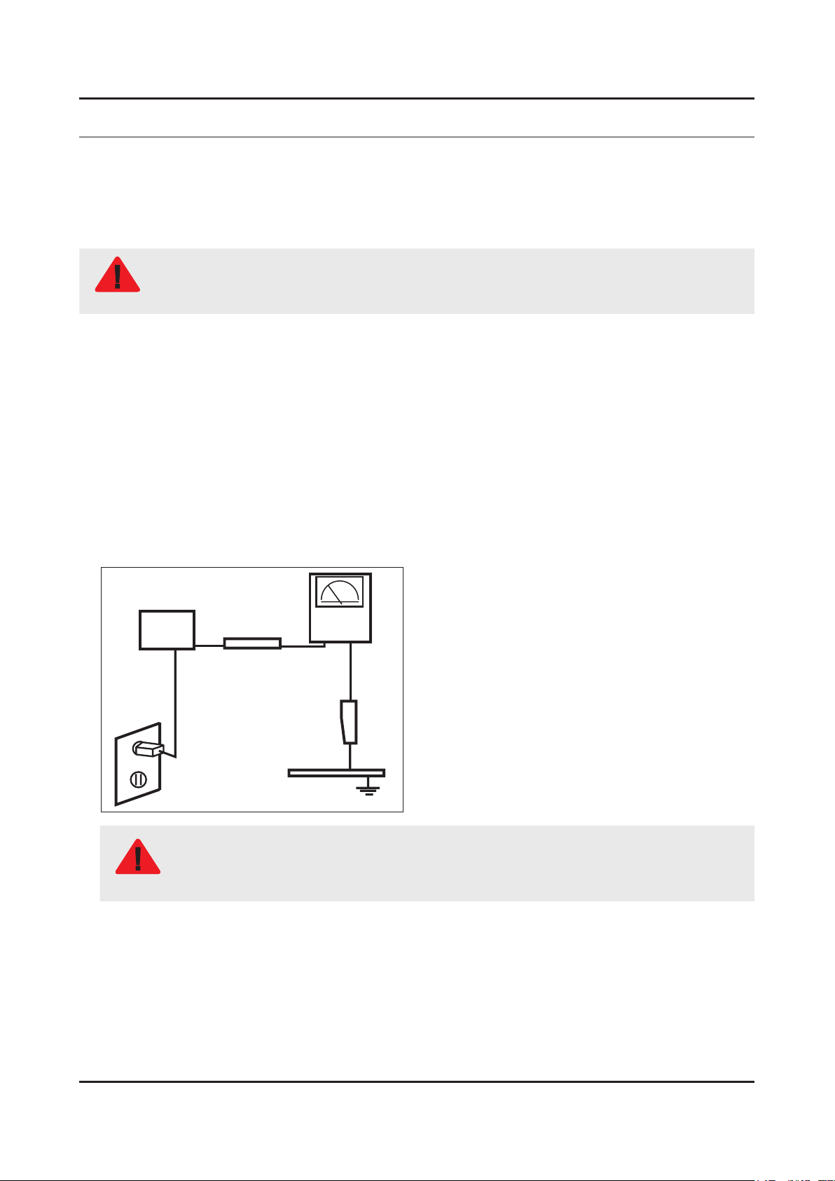
Leakage Current Hot Check:3.
Disconnect the AC power and DC power jack before servicing.
(READING SHOULD)
DEVICE
UNDER
TEST
ALSO TEST WITH
PLUG REVERSED
(USING AC ADAPTER
PLUG AS REQUIRED)
NOT BE ABOVE 0.5mA
2-WIRE CORD
TEST ALL
EXPOSED METAL
SURFACES
LEAKAGE
CURRENT
TESTER
EARTH
GROUND
Do not use an isolation transformer during this test.
Use a leakage current tester or a metering system that complies with American National Standards
WARNING
Institute (ANSI C101.1, Leakage Current for Appliances), and Underwriters Laboratories (UL
Publication UL1410, 59.7).
With the unit completely reassembled, plug the AC line cord directly into a 120V AC outlet. With the unit’s AC switch rst 4.
in the ON position and then OFF, measure the current between a known earth ground (metal water pipe, conduit, etc.)
and all exposed metal parts, including: metal cabinets, screwheads and control shafts.
The current measured should not exceed 0.5 milliamp.
Reverse the power-plug prongs in the AC outlet and repeat the test.
1-1
Page 18

1-2
1. Precautions
1-1-4. Product Safety Notices
Some electrical and mechanical parts have special safetyrelated characteristics which are often not evident from visual
inspection. The protection they give may not be obtained by replacing them with components rated for higher voltage,
wattage, etc. Parts that have special safety characteristics are identied by on schematics and parts lists. A substitute
replacement that does not have the same safety characteristics as the recommended replacement part might create
shock, re and/or other hazards. Product safety is under review continuously and new instructions are issued whenever
appropriate.
Page 19

1-3
1. Precautions
1-2. Servicing Precautions
An electrolytic capacitor installed with the wrong polarity might explode.
WARNING
Before servicing units covered by this service manual, read and follow the Safety Precautions section of
CAUTION
NOTE
1-2-1. General Servicing Precautions
Always unplug the unit’s AC power cord from the AC power source and disconnect the DC Power Jack before 1.
attempting to: (a) remove or reinstall any component or assembly, (b) disconnect PCB plugs or connectors, (c) connect
a test component in parallel with an electrolytic capacitor.
Some components are raised above the printed circuit board for safety. An insulation tube or tape is sometimes used. 2.
The internal wiring is sometimes clamped to prevent contact with thermally hot components. Reinstall all such elements
to their original position.
After servicing, always check that the screws, components and wiring have been correctly reinstalled. Make sure that 3.
the area around the serviced part has not been damaged.
Check the insulation between the blades of the AC plug and accessible conductive parts (examples: metal panels, input 4.
terminals and earphone jacks).
Insulation Checking Procedure: Disconnect the power cord from the AC source and turn the power switch ON. Connect 5.
an insulation resistance meter (500 V) to theblades of the AC plug. The insulation resistance between each blade of the
AC plug and accessible conductive parts (see above) should be greater than 1 megohm.
Always connect a test instrument’s ground lead to the instrument chassis ground before connecting the positive lead; 6.
always remove the instrument’s ground lead last.
this manual.
If unforeseen circumstances create conict between the following servicing precautions and any of the
safety precautions, always follow the safety precautions.
Page 20

1-4
1. Precautions
1-3. Static Electricity Precautions
Some semiconductor (solid state) devices can be easily damaged by static electricity. Such components are commonly
called Electrostatically Sensitive Devices (ESD). Examples of typical ESD are integrated circuits and some eld-effect
transistors. The following techniques will reduce the incidence of component damage caused by static electricity.
Immediately before handling any semiconductor components or assemblies, drain the electrostatic charge from your 1.
body by touching a known earth ground. Alternatively, wear a discharging wrist-strap device. To avoid a shock hazard,
be sure to remove the wrist strap before applying power to the monitor.
After removing an ESD-equipped assembly, place it on a conductive surface such as aluminum foil to prevent 2.
accumulation of an electrostatic charge.
Do not use freon-propelled chemicals. These can generate electrical charges sufcient to damage ESDs.3.
Use only a grounded-tip soldering iron to solder or desolder ESDs.4.
Use only an anti-static solder removal device. Some solder removal devices not classied as “anti-static” can generate 5.
electrical charges sufcient to damage ESDs.
Do not remove a replacement ESD from its protective package until you are ready to install it. Most replacement ESDs 6.
are packaged with leads that are electrically shorted together by conductive foam, aluminum foil or other conductive
materials.
Immediately before removing the protective material from the leads of a replacement ESD, touch the protective material 7.
to the chassis or circuit assembly into which the device will be installed.
Be sure no power is applied to the chassis or circuit and observe all other safety precautions.
CAUTION
Minimize body motions when handling unpackaged replacement ESDs. Motions such as brushing clothes together, or 8.
lifting your foot from a carpeted oor can generate enough static electricity to damage an ESD.
Page 21

1-5
1. Precautions
1-4. Installation Precautions
For safety reasons, more than a people are required for carrying the product.1.
Keep the power cord away from any heat emitting devices, as a melted covering may cause re or electric shock.2.
Do not place the product in areas with poor ventilation such as a bookshelf or closet. The increased internal temperature 3.
may cause re.
Bend the external antenna cable when connecting it to the product. This is a measure to protect it from being exposed 4.
to moisture. Otherwise, it may cause a re or electric shock.
Make sure to turn the power off and unplug the power cord from the outlet before repositioning the product. Also check 5.
the antenna cable or the external connectors if they are fully unplugged. Damage to the cord may cause re or electric
shock.
Keep the antenna far away from any high-voltage cables and install it rmly. Contact with the highvoltage cable or the 6.
antenna falling over may cause re or electric shock.
When installing the product, leave enough space (0.4m) between the product and the wall for ventilation purposes. 7.
A rise in temperature within the product may cause re.
If an equipment is provided with a replaceable battery, and if replacement by an incorrect type could result in an 8.
explosion (for example, with some lithium batteries), the following applies:
Risk of explosion if battery is replaced by an incorrect type dispose of used batteries according to •
the instructions.
Do not dispose of batteries in a re.•
Do not short circuit, disassemble or overheat the batteries.•
CAUTION
Danger of explosion if battery is incorrectly replaced. Replace only with the same or equivalent •
type.
Do not be exposed to excessive heat such as sunshine, re or the like.•
Page 22

2. Product Specications
2-1. Product information
Model UE58J5200AW
2. Product specications
W
Front View
Detail View
Color Front : Black, Stand : Black
Dimensions
(W x H x D)
Weight 58"
58"
With Stand 1308.0 x 836.6 x 306.9 mm / 51.9 x 32.9 x 12.1 inches
Without Stand 1308 x 770.4 x 88.7 mm / 51.9 x 30.3 x 3.5 inches
With Stand 19.1 kg / 42.1 lbs
Without Stand 17.5 kg / 38.6 lbs
H
* W : Width H : High D : Depth
D
2-1
Page 23

2-2
2. Product specications
2-2. Product specication
2-2-1. Detailed Specications
NOTE
Design and specications are subject to change without prior notice.
Item UE58J5200AWXXH
General Information
Display
Video
Product LED
Series 5
Country HUNGARY
Screen Size 58"
Resolution 1,920 x 1,080
Ultra Clear Panel N/A
Picture Engine HyperReal
PQI (Picture Quality Index) 200
Dynamic Contrast Ratio Mega Contrast
Micro Dimming N/A
Precision Black (Local Dimming) N/A
Nano Crystal Color N/A
Wide Color Enhancer (Plus) Yes
PurColor N/A
Auto Depth Enhancer N/A
Contrast Enhancer N/A
Audio
Auto Motion Plus N/A
Film Mode Yes
Natural Mode Support Yes
Peak Illuminator N/A
Dolby Digital Plus Dolby MS10
Virtual Surround DTS Studio Sound
DTS Codec DTS Premium sound 5.1
3D Sound N/A
Sound Customizer N/A
Sound Output (RMS) 20W(10W+10W)
Speaker Type Down Firing + Full Range
Woofer N/A
HD Audio N/A
Wallmount Sound Mode Yes
Multiroom Link N/A
Page 24

2-3
2. Product specications
Item UE58J5200AWXXH
Audio
Smart TV
Smart Interaction
Convergence
TV SoundConnect N/A
Samsung SMART TV Yes
Apps Yes
Games N/A
Multi-Link Screen N/A
Automated Content Recognition (ACR) N/A
Info Widget N/A
Vertical Enhancement N/A
Connected EPG N/A
Voice Interaction N/A
Voice Control N/A
Face recognition N/A
Motion control N/A
TV to Mobile - Mirroring N/A
Mobile to TV - Mirroring, DLNA Yes
Samsung SMART View N/A
Differentiation
Tuner/Broadcasting
Connectivity
Wireless TV On - Samsung WOL N/A
Notication - BLE N/A
Brieng On TV N/A
RVU N/A
WiDi N/A
WiFi Direct No
Sports Mode Basic
Digital Broadcasting DVB-T/C
Analog Tuner Yes
2 Tuner N/A
CI/CI+/2CI+ CI+(1.3)
MHP / MHEG / HbbTV / ACAP / GINGA /
OHTV
HDMI 2
USB 2
Component In (Y/Pb/Pr) 1
Composite In (AV) 1(common use for component Y)
N/A
Ethernet (LAN) 1
Headphone 1
Audio Out (Mini Jack) N/A
Page 25

2-4
2. Product specications
Item UE58J5200AWXXH
Connectivity
Design
Digital Audio Out (Optical) 1
RF In (Terrestrial / Cable input / Satellite
input)
Ex-Link ( RS-232C ) N/A
IR Out 1
CI Slot 1
Scart 1
MHL N/A
HDMI 3D Auto Setting N/A
HDMI A / Return Ch. Support N/A
HDMI Quick Switch N/A
Wireless LAN Adapter Support Yes
Wireless LAN Built-in N/A
Anynet+ (HDMI-CEC) N/A
Design High Glossy
Bezel Type NNB
Slim Type Slim
1/1(Common Use for Terrestrial)/0
Additional Feature
Front Color Black
Light Effect (Deco) N/A
Stand Type Black Quad
Swivel (Left/Right) Yes
Samsung 3D N/A
3D Converter N/A
Instant On N/A
Camera Built-in N/A
Processor N/A
21:9 Immersive Picture Mode N/A
SCSA Support N/A
Accessibility Yes(Zoom)
One Connect (Jack) N/A
Digital Clean View Yes
Auto Channel Search Yes
Auto Power Off Yes
BD Wise Plus N/A
Caption (Subtitle) Yes
Channel List USB-Clone Yes
Page 26

2-5
2. Product specications
Item UE58J5200AWXXH
Additional Feature
Eco Feature
Connect Share™ (HDD) N/A
ConnectShare™ (USB 2.0) Yes
Embeded POP Yes
EPG Yes
Extended PVR N/A
Game Mode Yes
OSD Language Local
Picture-In-Picture Yes
BT HID Built-in N/A
USB HID Support Yes
Smart Evolution Support N/A
Teletext (TTX) Yes
Time Shift N/A
Ultra Clean View N/A
Eco Mark Yes
Eco Label Yes
Accessory
Eco Sensor Yes
Energy Efciency Class A++
3D Active Glasses (Included) N/A
Remote Controller Model TM1250A
Batteries (for Remote Control) Yes
Samsung Smart Control (Included) N/A
Ultra Slim Wall Mount Support N/A
Mini Wall Mount Support Yes
Vesa Wall Mount Support Yes
Floor Stand Support N/A
TV Camera (Included) N/A
IR Extender Cable (Included) Yes (22 European Countries)
Wireless Keyboard (Included) N/A
Composite to Scart Gender (Included) N/A
User Manual Yes
E-Manual Yes
ANT-Cable N/A
Power Cable Yes
Slim Gender Cable N/A
Page 27

2-6
2. Product specications
2-2-2. Specications
Specications
Model UE58J5200AW
Item Description
Screen Size (Diagonal) 58 inches
Display Resolution 1,920 x 1,080
Input Signal Analog 0.7 Vp-p ± 5% positive at 75Ω, internally terminated
Input Sync Signal H/V Separate, TTL, P. or N.
AC Power Voltage & Frequency AC220-240V 50/60Hz
Environmental Considerations Operating Temperature: 50˚F ~ 104˚F (10˚C ~ 40˚C)
Operating Humidity: 10% ~ 80%, non-condensing
Storage Temperature: -4˚F ~ 113˚F (-20˚C ~ 45˚C)
Storage Humidity: 5% ~ 95%, non-condensing
Sound (Output) 20W (10W X 2)
Page 28

2-7
2. Product specications
2-3. Accessories
NOTE
The items’ colors and shapes may vary depending on the model.•
Cables not included in the package contents can be purchased separately.•
The part code for some accessories may differ depending on your region.•
Product Description Code. No Remark
Remote Control &
Batteries
(AAA x 2)
Power Cord 3903-000950
User manual BN68-07681D
Holder-Wire Stand BN61-08370A
BN59-01178B
4301-000121
Samsung Electronics
Service center
Page 29

4. Troubleshooting
4. Troubleshooting
4-1. Troubleshooting
4-1-1. Testing the Picture
MENU Support Self Diagnosis Picture Test Try Now
Before you review the list of problems and solutions below, use Picture Test to determine if the problem is caused by
the TV. The Picture Test displays a high denition picture you can examine for aws or faults. If the test picture does not
appear or there is noise or distortion, the TV may have a problem. Contact Samsung’s Call Center for assistance. If the
test picture is displayed properly, there may be a problem with an external device. Please check the connections. If the
problem persists,check the signal strength or refer to the external device’s user manual.
The Problem Try this!
If your Samsung Television is ickering or dimming sporadically, you may need
Flickering and Dimming.
Component Connections/
Screen Color
to disable some of the energy efciency features. Disable Energy Saving (System >
Eco Solution > Energy Saving) or Eco Sensor (System > Eco Solution > Eco Sensor).
If the color on your Samsung television screen is not correct or the black and
white colors are off, run Picture Test (Support > Self Diagnosis > Picture Test).
If the test results indicate that the problem is not caused by the TV, do the
following:
Conrm that the TV’s video input connectors are connected to the correct external •
device video output connectors.
Check the other connections as well. If the TV is connected to an external device •
via a component cable, conrm that the Pb, Pr, and Y jacks are plugged into their
proper connectors.
Screen Brightness
Ghosting, Blurring, or
Juddering
Unwanted Powering Off
Problems Powering On
If the colors on your Samsung TV are correct but just a little too dark or bright, try
adjusting the following settings rst.
Go to the • Picture menu and adjust the Backlight/Cell Light (available on different
models) Contrast, Brightness, Sharpness, Color, and Tint (G/R) settings.
If you notice ghosting or blurring on the screen, use the Auto Motion Plus option
(Picture > Picture Options > Auto Motion Plus) to resolve the issue.
NOTE
For the LED 5203, 5303 and 4303 series models, you can resolve this issue by using
LED Clear Motion (Picture > Picture Options > LED Clear Motion).
If your Samsung TV appears to turn off by itself, try disabling some of the TV’s energy
efciency features. See if Sleep Timer (System > Time > Sleep Timer) has been
enabled. The Sleep Timer automatically turns the TV off after a specied period of
time. If the Sleep Timer has not been enabled, see if No Signal Power Off (System >
Eco Solution > No Signal Power Off) or Auto Power Off (System > Eco Solution > Auto
Power Off) has been enabled and disable them.
When the TV is turned on, the remote control receiver ashes 5 times before the
screen turns on.
If you are having problems powering on your Samsung television, there are a number
of things to check before calling the service department. Conrm that the TV’s power
cord is connected correctly at both ends and that the remote control is operating
normally. Make sure that the antenna cable or cable TV cable is rmly connected. If
you have a cable/satellite box conrm that it is plugged in and turned on.
Unable to nd a Channel
If your TV is not connected to a cable box or satellite box, run Setup (System > Setup)
or Auto Program (Broadcasting > Auto Program).
4-1
Page 30

4-2
4. Troubleshooting
The Problem Try this!
The TV image does not look
as good as it did in the store.
The picture is distorted.
Store displays are all tuned to digital, HD (high denition) channels.
If you have an analog cable/set top box, upgrade to a digital set top box. Use HDMI or
Component cables to deliver HD (high denition) picture quality.
Many HD channels are upscaled from SD (Standard Denition) content. Look for a
channel that is broadcasting true HD content.
Cable/Satellite Subscribers: Try HD channels from the channel lineup.•
Air/Cable Antenna Connection: Try HD channels after running the Auto Program •
function.
Adjust the cable/satellite box’s video output resolution to 1080i or 720p.
The compression of video content may cause picture distortions, especially in fast moving
pictures from sports programs and action movies.
A weak or bad quality signal can cause picture distortions. This is not an issue with the TV.
Mobile phones used close to the TV (within 3.2 ft) may cause noise in analog and digital
channels.
The color is wrong or missing.
The color is poor or the picture
is not bright enough.
There is a dotted lineon the
edge of the screen.
The picture is black and white.
If you’re using a Component connection, make sure that the Component cables are connected to
the correct jacks. Incorrect or loose connections may cause color problems or a blank screen.
Go to the Picture menu and then adjust the Picture Mode, Brightness, Sharpness, and Color
settings. See if Energy Saving (System > Eco Solution > Energy Saving) has been enabled.
Try resetting the picture. (Picture > Picture Reset)
If the Picture Size has been set to Screen Fit, change the setting to 16:9.
Change the cable/satellite box resolution.
If you are using AV composite input, connect the video cable (yellow) to the TV’s green
component jack.
Page 31

4-3
4. Troubleshooting
4-1-2. Testing the Sound
MENU Support Self Diagnosis Sound Test Try Now
Before you review the list of problems and solutions below, make sure that the TV Sound Output menu item is set to TV
Speaker, and then listen to the speakers again. If the TV still does not play audio,run the Sound Test. The Sound Test
uses a built-in melody to check for sound problems. If the TV does not play sound during the Sound Test, or the sound is
distorted, there may be a problem with the TV. Contact Samsung’s Call Center for assistance. If the TV plays the Sound
Test melody without distortion, there may be a problem with an external device. Please check the connections. If the
problem persists, refer to the external device’s user manual.
The Problem Try this!
There is no sound or the
sound is too low at maximum
volume.
The picture is good but there
is no sound.
The speakers are making an
odd sound.
Check the volume control of the device (cable/satellite box, DVD, Blu-ray, etc.)
connected to your TV.
Set Sound > Speaker Settings > TV Sound Output to TV Speaker.
If you are using an external device, check the device’s audio output option. (For
example, you may need to change your cable box’s audio option to HDMI if the
box connected to your TV is using an HDMI cable.) To listen to the computer sound,
connect the external speaker to the computer’ s audio output connector.
If your TV has a headphone jack, make sure there is nothing plugged into it.
Reboot the connected device by disconnecting and then reconnecting the device’s
power cable.
Make sure that the audio cable is connected to the correct audio output connector
on the external device.
For antenna or cable connections, check the signal information. A low signal level
may cause sound distortions. Run Sound Test (Support > Self Diagnosis > Sound
Test).
Page 32

4-4
4. Troubleshooting
4-1-3. Testing the 3D Picture Quality
MENU Support Self Diagnosis 3D Picture Test
NOTE
To test 3D picture quality, you must be wearing 3D glasses and the glasses and the TV must be paired.
3D is not available in the U.S.A. and Canada and is only available on LED 6200 series TVs or higher. Before you review
the list of problems and solutions below, use 3D Picture Test to determine if the problem is caused by the TV. The 3D
Picture Test displays a high denition picture you can examine for aws or faults. If the test picture does not appear or
there is noise or distortion, the TV may have a problem. Contact Samsung’s Call Center for assistance. If the test picture
is displayed properly, there may be a problem with an external device. Please check the connections. If the problem
persists, check the signal strength or refer to the external device’s user manual.
The Problem Try this!
Make sure the glasses are powered on.
The 3D glasses are not
working correctly.
The 3D feature may not work properly if there is another 3D product or an electronic
device running nearby. If there is a problem, keep other electronic devices as far
away as possible from the 3D Active Glasses.
I can’t see 3D images clearly.
The batteries in the 3D
glasses are at.
The ideal viewing distance is three times or more the height of the screen.
We also recommend watching 3D content with your eyes level with the screen.
Turn off the 3D glasses when they are not in use. If you leave the 3D glasses on,
the battery lifespan is shortened.
4-1-4. There is a problem with the broadcast
The Problem Try this!
If your TV is not connected to a cable box or satellite box:
The TV is not receiving all
channels.
There are no captions with
digital channels.
The picture is distorted.
Conrm that the coaxial cable is securely connected to the TV.•
If you are using an antenna, verify it is positioned correctly and the all the •
connections are secure.
Run • Setup (System > Setup) or Auto Program (Broadcasting > Auto Program).
Go to Caption (System > Accessibility > Caption) and change the Caption Mode.
Some channels may not have caption data.
The compression of the video content may cause picture distortions. This is
especially true with fast moving pictures from sports programs and action movies.
A weak signal can cause picture distortions. This is not a problem with the TV.
4-1-5. My computer won’t connect
The Problem Try this!
The "Mode Not Supported"
message appears.
The video is OK but there is
no audio.
Set your PC’s output resolution so it matches a resolution supported by the TV.
If you are using an HDMI connection, check the audio output setting on your PC.
If you are using a DVI to HDMI cable, a separate audio cable is required.
Page 33

4-1-6. I can’t connect to the Internet
4-5
4. Troubleshooting
The Problem Try this!
The wireless network
connection failed.
The software update over the
Internet has failed.
Conrm your wireless modem/router is on and connected to the Internet.
Reset your wireless modem/router by turning it off, waiting for 15 seconds, and then
turning it on again. Run Network Setup (MENU > Network > Network Settings).
Check the network connection status (MENU > Network > Network Status).
If the TV is not connected to a network, connect to a network.
The upgrade stops if you already have the latest software version.
4-1-7. My le won’t play
The Problem Try this!
Some les can’t be played.
This problem may occur with high-bitrate les. Most les can be played back, but
you might experience problems with high-bitrate les.
4-1-8. I am having trouble launching/using apps
The Problem Try this!
I launched an app, but it’s in
English.
How can I change the
language?
Languages supported by the app may be different from the user interface language.
The ability to change the language depends on the service provider.
My application is not working.
Check with the service provider.
Refer to the help section on the application service provider’s website.
4-1-9. I want to reset the TV
Reset Path Description
Reset Settings
Resetting Smart
Hub
MENU > Support > Self Diagnosis
> Reset
MENU > Smart Hub >Smart Hub Reset
Reset Picture, Sound, Channel, Smart Hub, and all other
settings, except for the network settings, default settings.
Resets all Smart Hub settings to their factory defaults and
deletes all information related to Samsung accounts, linked
service accounts, Smart Hub service agreements, and Smart
Hub applications.
Page 34

4-6
4. Troubleshooting
4-1-10. Other Issues
The Problem Try this!
The TV is hot.
The picture won’t display in full
screen.
Watching TV for an extended period of time causes the panel to generate heat.
The heat from the panel is dissipated through internal vents running along the top of
the TV. The bottom, however, may feel hot to the touch after extended use. Children
watching TV need constant adult supervision to prevent them from touching the TV.
This heat, however, is not a defect and does not affect the TV’s functionality.
HD channels will have black bars on either side of the screen when displaying
upscaled SD (4:3) content. Black bars will appear at the top and bottom of the
screen when you watch movies that have aspect ratios different from your TV.
Adjust the picture size options on your external device or set the TV to full screen.
The "Mode Not Supported"
message appears.
The Captions item in the TV menu
is grayed out.
The TV smells of plastic. This smell is normal and will dissipate over time.
The Signal Information option
under Self Diagnosis isn’t
activated.
The TV is tilted to the side. Remove the base stand from the TV and reassemble it.
The Broadcasting option has been
deactivated.
The settings are lost after 5
minutes or every time the TV is
turned off.
There is an intermittent loss of
audio or video.
There are small particles on the
TV’s bezel.
The PIP menu is not available.
A POP (TV’s internal banner ad)
appears on the screen.
The output resolution of the attached device is not supported by the TV. Check the TV’s
supported resolutions and adjust the external device’s output resolution accordingly.
You cannot select the Caption menu if you have selected a source connected to the TV via
HDMI or Component. To view captions, turn on the external device’s caption function.
Verify that the current channel is a digital channel.
The Signal Information is only available for digital channels.
Broadcasting is only available when the Source is set to TV.
The Broadcasting menu cannot be accessed while you watch TV using a cable box or satellite
receiver.
If the Use Mode is set to Store Demo, the TV’s audio and video settings are automatically reset
every 5 minutes. Change the Use Mode (Support > Use Mode) to Home Use.
Check the cable connections and reconnect them. Loss of audio or video can be caused by
using overly rigid or thick cables. Make sure the cables are exible enough for long term use. If
you are mounting the TV to a wall, we recommend using cables with 90-degree connectors.
This is part of the product’s design and is not a defect.
PIP functionality is only available when you are viewing video from an HDMI or Component
source on the main screen.
Change the Use Mode (Support > Use Mode) to Home Use.
The TV is making a popping noise.
The TV is making a humming
noise.
The expansion and contraction of the TV’s outer casing may cause a popping noise. This does
not indicate a product malfunction. The TV is safe to use.
Your TV utilizes high-speed switching circuits and high levels of electrical current. Depending
on the TV’s brightness level, the TV may seem slightly noisier than a conventional TV.
Your TV has undergone strict quality control procedures that meet our demanding performance
and reliability requirements. Some noise coming from the TV is considered normal and is not
an acceptable cause for an exchange or refund.
Page 35

4-2. Connect
4-7
4. Troubleshooting
Page 36

4-8
4. Troubleshooting
4-3. Factory Mode Adjustments
4-3-1. Detail Factory Option
NOTE
If you replace the main board with new one, please change the factory option as well.
The options you must change are "Type".
UE58J5200AWXXH
Inches 58"
Vendor INX
PANEL
SMPS BOARD
MAIN BOARD
Byte Item
0 Factory Reset -
1 Type 58D6AF0S
2 Local set EU
3 SW Model UJ5200
4 BOM Model 5200
5 Tuner Auto
Code BN95-01724A
Spec. HH058BGNV1H/V
Vendor SEM
Code BN44-00787A
Spec. L58GFB_ESM
Chassis Ass'y BN91-16918M
PBA Ass'y BN94-10476C
Page 37

4-3-2. Entering Factory Mode
4-9
4. Troubleshooting
To enter ‘Service Mode’ Press the remote -control keys in this sequence :
If you do not have Factory remote control•
Power OFF INFO MENU MUTE Power On
If you have Factory remote control•
INFO Factory
If you don’t have Factory remote control, can’t control some menus•
Initial SERVICE MODE DISPLAY State
Page 38

4-10
4. Troubleshooting
4-3-3. Factory Data
Option
Factory Menu Name Data Range
Factory Reset
Type
Local Set
Model
SVC Model
TUNER
Ch Table
-
58D6AF0S
-
UJ5200
5200
Auto
NONE
MRT Option
Front Color U-S-C-MEGA
Lvds Format JEIDA
Language_Arabic US
Region USA
PnP Language ENG_US
WIFI REGION S
OTN Support ON
OTA Support OFF
MediaPlay DLNA …
TTX OFF
China HD OFF
NT Conversion OFF
Num of DTV 1
Num of AV 1
Num of COMP 1
Num of HDMI 2
Num of SCART 0
Num of USB Port 2
Num of USB 3.0 0
Num of RVU 0
Num of Display 2
Num of IPTV 0
Num of RUI 0
Num of PVR RECORD 0
TOOLS Support 40
LNA Support OFF
24Px4 Support OFF
Page 39

Factory Menu Name Data Range
4-11
4. Troubleshooting
BD Wise Support OFF(H6203 ON)
Data Service Support OFF
PVR Support OFF
CI Support OFF
LEDMotionPlus Support ON
Natual Mode Support ON
Relax Mode Support OFF
HDMI/DVI SEL 2
Select LED/PDP LCD
Wall Mount OFF
HV Flip HV Filp
FRC HV Flip 0
Light Effect OFF
e-Pop Default ON
CAMERA Support OFF
NETWORK Support Int-Wi
EcoSensor Support ON
3D Support OFF
BT Support OFF
BT ADDRESS Not support
HP LINE LineOut
Smart Control Support OFF
Motion Recog OFF
Voice Recog OFF
Virtual Remocon color 1
Local Dimming Panel OFF
Wi Vendor QCA
Engineer Option
Type Of PANEL KEY None
5 Way Function Key R_BACK
Contents Bar OFF
Cable Modulation QAM
Standby led on/off OFF
Recognition Support OFF
IF AGC 0
D AGC 0
PH BW 0
FQ BW 0
Page 40

4-12
4. Troubleshooting
Factory Menu Name Data Range
PH RATE 0
PD EN 0
PEQ Inx 0
WF Scale
WF Type 0
Num of Network Stream 1
DP V Size 0
Backend Device
BT_AUDIO_ON_OFF OFF
Cong_AV_PATH
USING_PSI_UPDATE
ECO Stanby OFF
Fast Logo Delay 0
Num of PANEL KEY
Panel Detail 0
Panel Init Time 250
Tcon Init Time 460
WRITE MAC Address
Control
Factory Menu Name Data Range
EDID
EDID ON/OFF OFF
EDID WRITE ALL …
EDID WRITE PC …
EDID WRITE HDMI …
EDID WRITE HDMI1 …
EDID WRITE HDMI2 …
EDID WRITE HDMI3 …
EDID WRITE HDMI4 …
EDID Ver …
EDID Port
EDID WRITE DVI …
Sub Option
RS-232 Jack UART Debug/UART
Serial Log On/Off OFF ON/OFF
Watchdog OFF
Page 41

Factory Menu Name Data Range
4-13
4. Troubleshooting
FRC Monitoring OFF
Checksum 0x0000
Fast Boot in Production ON
UART ENABLE OFF
ECO IC TYPE MC8121
Info Link Server Type development
Info Link Country None
TTX Group …
Visual Test …
MediaPlay DB …
OPTION_SWU
OPTION_NUM
RF Remocon Support OFF
CCD mode …
DONS Support OFF
Num of IPTV CIP 0
Num of CI 0
Num of HYBRID TV 0
T-CON Device
BOARD CONTROL OFF
RM
PSA
LMK threshold 4
Low threshold 10
High threshold 15
CSB ON
CLB ON
EEPG Enable 0
Last Screen OFF
App Resume OFF
BP PMS Reset 1
F Anet Thread 2
ACM_MC OFF
Support MiniBrowser ON
HotkeyList Basic_Smart
PDP Option
Pixel Shift Test OFF
Logic SW
Page 42

4-14
4. Troubleshooting
Factory Menu Name Data Range
Panel Temperature
LOGIC Waveform Day
Logic Check Sum
MRT
SAPC Timer
APC Speed
Hotel Option
Hospitality Mode OFF
Power On
Menu OSD
Operation
Music Mode
External Source
Eco Solution
Cloning
Shop Option
Shop Mode OFF
Exhibition Mode OFF
3D Cube OFF
Asia Option
Unbalance
AF Level adjust
TX Power Level
Mono Last Memory
H Shaking
SOUND
Carrier_Mute ON
High Devi OFF
Speaker Delay Normal 10
SPDIF PCM Gain -9 dB
FM M Prescale 48
FM Prescale 0x00h
AM Prescale 0x32h
NICAM Prescale 0x48h
BTSC Mono Prescale 15
BTSC stereo Prescale 29
BTSC SAP Prescale 29
A2Ident High Thid 36
Page 43

Factory Menu Name Data Range
4-15
4. Troubleshooting
A2Ident Low Thid 9
Pilot Level High Thld 0x0Fh
Pilot Level Low Thld 0x08h
Carrier2 Amp High Thld 4
Carrier2 Amp Low Thld 3
Carrier2 SNR High THR 16
Carrier2 SNR Low THR 80
Sig Error On 35
Sig Error Off 41
Amp Model TAS5745
Amp Volume 0xc9h
Amp Scale 0x35h
Amp Check Sum 0x00480W60
Woofer Type 0
Woofer Volume 0xcbh
Woofer Scale 0x8ah
Woofer Check Sum NONE
Woofer Local EQ Checksum 0
Speaker EQ ON
PEQ Test Ready
Lacal Speaker EQ 0
Local EQ Checksum 0
SRS Tuning Parm 0
Subwoofer Support 0
India Sound OFF
AudioDock BT delay 50
Wall Filter Type 0
Bottom CheckSum 0
Bottom Local Checksum 0
Lipsync lnx 2
Lipsync checkSum NG
Lipsync USB Test Ready
Lipsync BT Checksum NG
Debug
Factory Menu Name Data Range
Spread Spectrum
Page 44

4-16
4. Troubleshooting
Factory Menu Name Data Range
LVDS Spread ON
DDR Spread OFF
Period 20K
Amplitude 1.5
HD SSC ON/Off OFF
HD SSC Value 1
LVDS SSC ON/OFF OFF
LVDS Value 0
DDR SSC ON/OFF OFF
DDR SSC Value 1
FRC Vx1 SSC ON/OFF OFF
FRC LVDS SSC ON/OFF OFF
FRC LVDS SSC MRR 10
FRC LVDS SSC MFR 1
FRC Vx1 SSC Period 0
FRC Vx1 SSC Modulation 0
FRC DDR SSC ON/OFF ON
FRC DDR SSC MRR 15
FRC DDR SSC MFR 1
FRC DDR SSC Period 0
FRC DDR SSC Modulation 0
DDR Margin
A CTRL_OFFSET_0_3 0
A CTRL_OFFSET_D 0
B CTRL_OFFSET_0_3 0
B CTRL_OFFSET_D 0
MICOM POWER OFF OFF
RF Mute Time 6ms
CI +1.3 OFF
FRC
Tuner Margin 10
MPEG Margin 100
H.264 Margin 100
CAM Wait Time
TS Clock delay 0
TCON_TEMP_READ 0
TEMP LAST 60
DCC VERSION 0x3447
Page 45

Factory Menu Name Data Range
4-17
4. Troubleshooting
DCC CHK SEL 0
DCC CHECK LOCAL 0
DCC CHECK TOTAL 0
MultiACC Checksum 0
IIC Bus Stop OFF
Tuner Status
Cert Option SHOW
RM_BIST_DTV 0
RM_BIST_ATV 0
Voice Debug OFF
SVC
Factory Menu Name Data Range
Self Test(for HW)
Loop Back
CPU
DDR
FLASH
EEPROM
Tuner X-TAL
Tuner1
HDMI Switch IC
USB HUB IC
WIFI
LVDS
LVDS2
T-CON/FRC
T-CON2/FRC
PCB Test
MOIP
BT
EcoSensor
Voltage
Chip Test
Module Test
ATV CH Inspection
DTV CH Inspection
Page 46

4-18
4. Troubleshooting
Factory Menu Name Data Range
Satellite CH Inspection
Woofer Sound Inspection
DP Test
DP CRC Result
Voltage Result
BT
Chip Test
Module Test
ATV CH Inspection
DTV CH Inspection
Satellite CH Inspection
UHD OSD TEST
Aging Line Test
Tweeter Sound Inspection
Info
SVC Info
LOG(View Log)
ER Count
Panel Display Time
Factory Execution History
Factory Reset History
Upgrade
T-CON Usb Download
T-CON CheckSum
Logic Usb D/L
SUBMICOM UPGRADE
BT UPGRADE
BT FREEPAIRING
Function Upgrade
FRC3D FW UPGRADE
FRC3D LD UPGRADE
Camera Upgade
Mic Upgrade
CPLD USB Download
JP MICOM UPGRADE
DP MICOM UPGRADE
Jump UPGRADE
IR Blaster Upgrade
Page 47

Factory Menu Name Data Range
4-19
4. Troubleshooting
IR Blaster delay time
CPLD Download
LDC PROFILE UPGRADE
Pic Data USB Update
Audio Data USB Update
Eco Data USB Upate
SC ADK Upgrade
SC MBR Upgrade
Reset
App Reset 0
EEPROM Rst 0
SPI Flash Reset Failure
OPTION_HDMI
DVI/HDMI SOUND Auto
HDMI HOT PLUG Disable
HOTPLUG SWITCHING boot
HOTPLUG DURATION 1200ms
CLK TERM DURATION 1200ms
HDMI FLT CNT SIG 100ms
HDMI FLT CNT LOS 100ms
UNSTABLE BAN CNT 5000ms
HDMI ROBIN ON
HDMI Callback OFF
HDMI CTS Thld 8
HDMI CTS Cnt1 1
HDMI EQ Auto
HDMI Write Type Combine
HDMI Switch NONE
DVI SET TIME 300ms
HDMI Sync DE
HDMI 3D DET 0
HOTPLUG OFF HOLD TIME
HDMI Stable Count 1
HDCP UPDATE SPI
SPI VERSION 0
DVB CI
TS Clock delay TC 0
TS Clock delay S 0
Page 48

4-20
4. Troubleshooting
Factory Menu Name Data Range
CI Control Buf ON ON
TS Clock delay CPU -1
Test Pattern
Pattern Sel OFF
Logic Pattern Sel
Logic Level Sel
FRC Pre Test Pattern 0
FRC Post Test Pattern 0
SOC TCON Test Pattern 0
SOC TCON Pattern Level 255
SOC TCON FRC Pattern 0
HDMI WB Pattern OFF
HDMI Pattern Sel 0
Parma Pre Test Pattern 0
Parma Port Test Pattern 0
FRC OSD PRE PATTERN 0
FRC OSD POST PATTERN 0
Other Setting
Delete S/N 0
IPERF stopped
Expert
CAL Data Backup
CAL Data Restore
ATV IF AGC SPEED
Source Direct ON/OFF 0
App Update LAST POWER
SVC Panel
ORIGINAL
ADC/WB
Factory Menu Name Data Range
ADC
AV Calibaration
Comp Calibration
PC Calibration
HDMI Calibration
ADC Result
1st_Y_GH 0
Page 49

Factory Menu Name Data Range
4-21
4. Troubleshooting
1st_Y_GL 0
1st_Cb_BH 0
1st_Cb_BL 0
1st_Cr_RH 0
1st_Cr_RL 0
2nd_R_L 134
2nd_G_L 134
2nd_B_L 134
2nd_R_H 49
2nd_G_H 49
2nd_B_H 49
White Balance
R-Offset 128
G-Offset 128
B-Offset 128
R-Gain 128
G-Gain 128
B-Gain 128
WB-W2_R_Offset
WB_W2_B_Offset
WB_W2_R_Gain
WB_W2_B_Gain
WB-N_R_Offset
WB_W2_N_Offset
WB_W2_N_Gain
WB_W2_N_Gain
MGA
MGA On/Off OFF
R1_Gain
G1_Gain
B1_Gain
R2_Gain
G2_Gain
B2_Gain
R3_Gain
G3_Gain
B3_Gain
R4_Gain
Page 50

4-22
4. Troubleshooting
Factory Menu Name Data Range
G4_Gain
B4_Gain
R5_Gain
G5_Gain
B5_Gain
R6_Gain
G6_Gain
B6_Gain
R7_Gain
G7_Gain
B7_Gain
R8_Gain
G8_Gain
B8_Gain
R9_Gain
G9_Gain
B9_Gain
R10_Gain
G10_Gain
Advanced
Page 51

4-4. White Balance
4-23
4. Troubleshooting
4-4-1. Calibration
Into the Factory Mode.1.
Select 2. SVC Menu.
Select 3. ADC/WB menu.
Select 4. ADC menu.
Option
Control
Debug
SVC
ADC/WB
Advanced
4-4-2. Service Adjustment
You must perform Calibration in the Lattice Pattern before adjusting the White Balance.
ADC
AV Calibration
Comp Calibration
HDMI Calibration
Color Calibration
Adjust Specication•
Source Setting Mode Pattern Use Equipment
HDMI 1280 x 720@60 Hz Pattern #24 (Chess Pattern) CA210 & Master MSPG925 Generator
(Chess Pattern)
Use other equipment only after comparing the result with that of the Master equipment. -
Input mode Calibration Pattern
CVBS IN (Model_#1) Perform in NTSC B&W Pattern #24 Lattice
Component IN (Model_#6) Perform in 720p B&W Pattern #24 Lattice
HDMI IN Perform in 720p B&W Pattern #24 Lattice
Page 52

4-24
4. Troubleshooting
Method of Color Calibration (AV)
Apply the NTSC Lattice (N0. 3) pattern signal to the AV IN 1 port.1.
Press the Source key to switch to “AV1” mode.2.
Enter Service mode.3.
Select the “ADC” menu.4.
Select the “AV Calibration” menu.5.
In “AV Calibration Off” status, press the “► ” key to perform Calibration.6.
When Calibration is complete, it returns to the high-level menu.7.
You can see the change of the “AV Calibration” status from Failure to Success. 8.
Method of Color Calibration (Component)
Apply the 720p Lattice (N0. 6) pattern signal to the Component IN 1 port.1.
Press the Source key to switch to “Component1” mode.2.
Enter Service mode.3.
Select the “ADC” menu.4.
Select the “Comp Calibration” menu.5.
In “Comp Calibration Off” status, press the “ ►” key to perform Calibration.6.
When Calibration is complete, it returns to the high-level menu.7.
You can see the change of the “Comp Calibration” status from Failure to Success.8.
Method of Color Calibration (HDMI)
Apply the 720p Lattice (N0. 6) pattern signal to the HDMI1/DVI IN port.1.
Press the Source key to switch to “HDMI1” mode.2.
Enter Service mode.3.
Select the “ADC” menu.4.
Select the “HDMI Calibration” menu.5.
In “HDMI Calibration Off” status, press the “►” key to perform Calibration.6.
When Calibration is complete, it returns to the high-level menu.7.
You can see the change of the “HDMI Calibration” status from Failure to Success.8.
Page 53

4-4-3. Adjustment
4-25
4. Troubleshooting
Into the Factory Mode.1.
Select 2. SVC Menu.
Select 3. ADC/WB menu.
Select 4. WB menu.
Option
Control
Debug
SVC
ADC/WB
Advanced
White Balance
(Low light)
Sub Bright
R offset
G offset
B offset
(High light)
Sub Contrast
R gain
G gain
B gain
Page 54

4. Troubleshooting
4-5. Software Upgrade
Samsung may offer upgrades for the TV’s rmware in the future. These upgrades can be performed via the TV when it is
connected to the Internet, or by downloading the new rmware from samsung.com to a USB memory device.
Alternative Software (Backup) shows The previous version that will be replaced.•
Software is represented as ‘Year/Month/Day_Version’. The more recent the date, the newer the software version •
Installing the latest version is recommended.
4-5-1. By USB
Insert a USB drive containing the rmware upgrade downloaded from samsung.com into the TV. Please be careful to not
disconnect the power or remove the USB drive while upgrades are being applied.
"MENU-->Support--> Software Update"
The TV will turn off and turn on automatically after completing the rmware upgrade. Please check the rmware version
after the upgrades are complete (the new version will have a higher number than the older version). When software is
upgraded, video and audio settings you have made will return to their default (factory) settings. We recommend you write
down your settings so that you can easily reset them after the upgrade.
4-5-2. By Online
Upgrades the software using the Internet.
First, congure your network. For detailed procedures on using the Network Setting, refer to the ‘Setting the Network’ •
instructions.
If The internet connection doesn’t operate properly, connection can be broken, please retry downloading. If the •
problem still happens, download by USB and upgrade.
4-5-3. Alternative Software (Backup)
If there is an issue with the new rmware and it is affecting operation, you can change the software to the previous
If Software was changed, existing Software is displayed.•
you can change current Software to Alternative Software by ‘Alternative Software’.•
4-26
Page 55

5. Wiring Diagram
Main Board
Power Board
Speaker
FUNCTION& IR
Speaker
CN202
CN1201_FHD
CN1202_HD
CN302
CN402
CNL802
PANEL
PANEL
CNM803
S
p
e
a
kkk
kkk
e
r
5-1. Wiring Diagram
5. Wiring Diagram
5-1
Page 56

5-2
5. Wiring Diagram
5-2. Connector Functions
Connector Function
CN201 CNM803
CN1201 T-CON
Supply main power and dimming signal from IP Board to Main Board.
The LVDS signal transfered from Main Board to Panel.
Page 57

5-3
5. Wiring Diagram
5-3. Cables
Use Model LEAD CONNECTOR (Main-IP) LVDS CALBE (FHD)
Code
No.
Image /
Use Model FUNCTION HARNESS FUNCTION
Code
No.
Image /
UE58J5200 BN39-01889K BN96-33236H
UE58J5200 BN39-01910A BN96-30902V
 Loading...