

Samsung ue32f6100aw, ue40f6100aw, ue46f6100aw, ue55f6100aw Service manual
LED TV
Chassis : U88A
Model : UE32F6100AW
UE40F6100AW
UE46F6100AW
UE55F6100AW
SERVICE
LED TV Contents
1. Precautions
2. Product specications
3. Disassembly and Reassembly
4. Troubleshooting
5. Wiring Diagram
Manual
UE**F6100AW

Contents
1. Precautions ...................................................................................................................1-1
1-1. Safety Precautions ..............................................................................................................1-1
1-1-1. Warnings ...................................................................................................................1-1
1-1-2. Servicing the LED TV ...............................................................................................1-1
1-1-3. Fire and Shock Hazard .............................................................................................1-1
1-1-4. Product Safety Notices ............................................................................................. 1-2
1-2. Servicing Precautions ..........................................................................................................1-3
1-2-1. General Servicing Precautions ................................................................................. 1-3
1-3. Static Electricity Precautions ...............................................................................................1-4
1-4. Installation Precautions .......................................................................................................1-5
2. Product Specications.................................................................................................2-1
2-1. Product Specications .........................................................................................................2-1
2-2. Detailed Specications ........................................................................................................2-7
2-2-1. Model Comparison ...................................................................................................2-7
2-2-2. Feature & Specications ........................................................................................... 2-8
2-3. Accessories .......................................................................................................................2-12
2-4. Viewing the Functions ......................................................................................................2-13
2-4-1. Auto Motion Plus 120 Hz ........................................................................................ 2-13
2-4-2. Supported Formats .................................................................................................2-14
2-4-3. 3D Display ..............................................................................................................2-17
3. Disassembly and Reassembly ....................................................................................3-1
3-1. Disassembly and Reassembly ............................................................................................3-1
3-1-1. LED TV .....................................................................................................................3-1
3-1-2. ASSY BOARD P-RF-MODULE ............................................................................... 3-10
4. Troubleshooting ...........................................................................................................4-1
4-1. Troubleshooting ...................................................................................................................4-1
4-1-1. Previous Check ........................................................................................................4-1
4-1-2. Simple ow chart of malfunction ...............................................................................4-3
4-2. How to Check Fault Symptom .............................................................................................4-4
4-2-1. NO Power .................................................................................................................4-4
4-2-2. No Video (Tuner_CVBS) ..........................................................................................4-7
4-2-3. No Vido (Tuner DTV) ..............................................................................................4-10
4-2-4. No Video (Video AV) ...............................................................................................4-13
4-2-5. No Video (COMPONENT) ......................................................................................4-16
4-2-6. No Sound (1.Speaker 2.Monitor_out 3.Optical) .................................................. 4-19
4-3. Factory Mode Adjustments ................................................................................................4-22
4-3-1. Detail Factory Option ..............................................................................................4-22
4-3-2. Entering Factory Mode ...........................................................................................4-23
4-3-3. Factory Data ...........................................................................................................4-24

4-4. White Balance ...................................................................................................................4-37
4-4-1. Calibration ..............................................................................................................4-37
4-4-2. Service Adjustment ................................................................................................. 4-37
4-4-3. Adjustment .............................................................................................................. 4-38
4-5. AV Control Tabe .................................................................................................................4-39
4-6. Software Upgrade ..............................................................................................................4-45
4-6-1. How to Check the Software Version .......................................................................4-45
4-6-2. How to Upgade Software ........................................................................................ 4-46
4-7. The Dimension ..................................................................................................................4-48
4-7-1. UE32F6100AW ....................................................................................................... 4-48
4-7-2. UE40F6100AW ....................................................................................................... 4-49
4-7-3. UE46F6100AW ....................................................................................................... 4-50
4-7-4. UE55F6100AW ....................................................................................................... 4-51
5. Wiring Diagram .............................................................................................................5-1
5-1. Wiring Diagram ....................................................................................................................5-1
5-2. Connector ............................................................................................................................5-2
5-3. Connector Functions ...........................................................................................................5-5
5-4. Cables .................................................................................................................................5-6
5-5. The types of module ............................................................................................................5-7
1. Precautions
1. Precautions
1-1. Safety Precautions
Follow these safety, servicing and ESD precautions to prevent damage and to protect against potential hazards such as
electrical shock.
1-1-1. Warnings
For continued safety, do not attempt to modify the circuit board.
WARNING
1-1-2. Servicing the LED TV
When servicing the LED TV, Disconnect the AC line cord from the AC outlet.1.
It is essential that service technicians have an accurate voltage meter available at all times. Check the calibration of this 2.
meter periodically.
1-1-3. Fire and Shock Hazard
Before returning the monitor to the user, perform the following safety checks:
Inspect each lead dress to make certain that the leads are not pinched or that hardware is not lodged between the 1.
chassis and other metal parts in the monitor.
Inspect all protective devices such as nonmetallic control knobs, insulating materials, cabinet backs, adjustment and 2.
compartment covers or shields, isolation resistorcapacitor networks, mechanical insulators, etc.
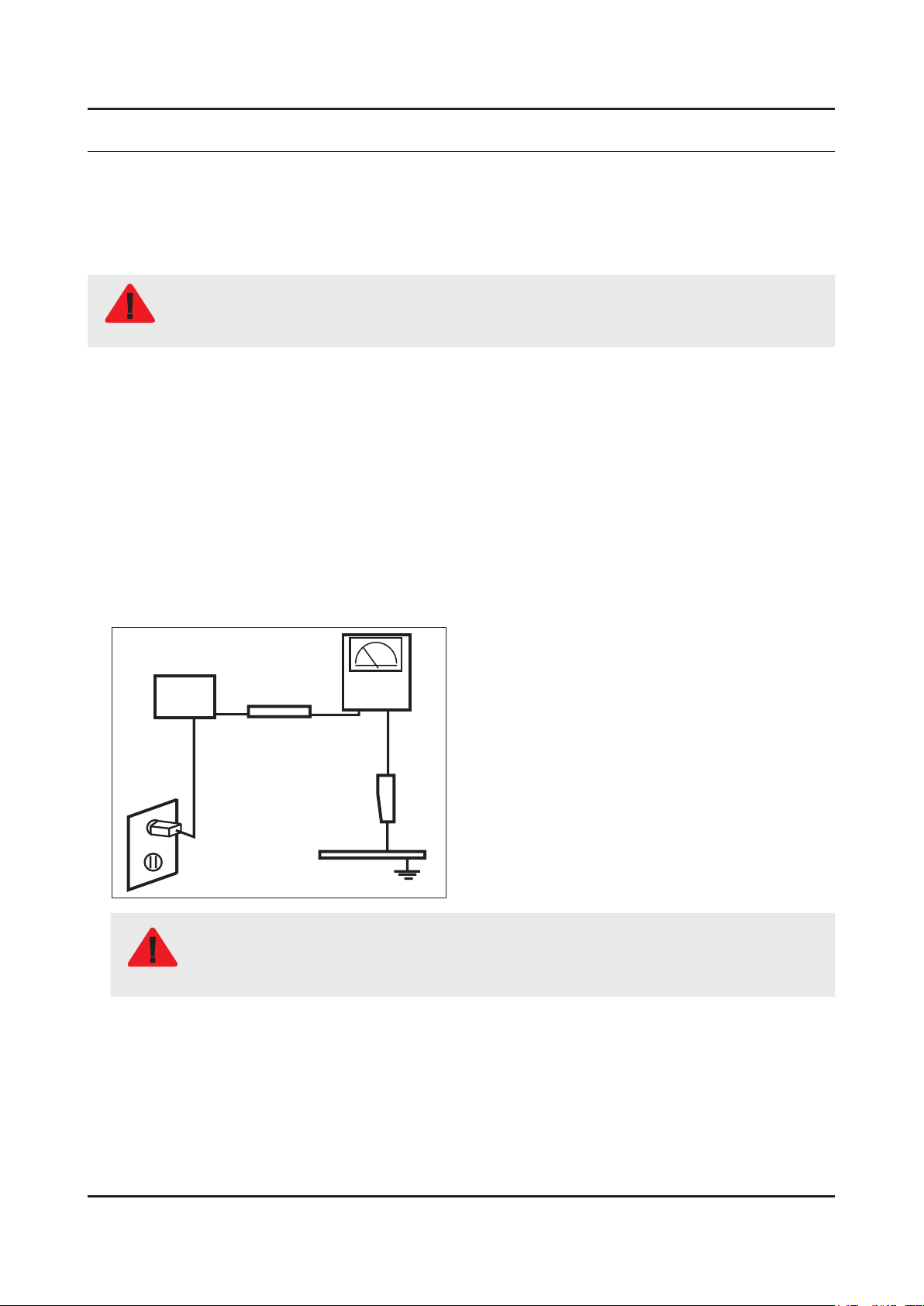
Leakage Current Hot Check:3.
Disconnect the AC power and DC power jack before servicing.
(READING SHOULD)
DEVICE
UNDER
TEST
ALSO TEST WITH
PLUG REVERSED
(USING AC ADAPTER
PLUG AS REQUIRED)
NOT BE ABOVE 0.5mA
2-WIRE CORD
TEST ALL
EXPOSED METAL
SURFACES
LEAKAGE
CURRENT
TESTER
EARTH
GROUND
Do not use an isolation transformer during this test.
Use a leakage current tester or a metering system that complies with American National Standards
WARNING
Institute (ANSI C101.1, Leakage Current for Appliances), and Underwriters Laboratories (UL
Publication UL1410, 59.7).
With the unit completely reassembled, plug the AC line cord directly into a 120V AC outlet. With the unit’s AC switch rst 4.
in the ON position and then OFF, measure the current between a known earth ground (metal water pipe, conduit, etc.)
and all exposed metal parts, including: metal cabinets, screwheads and control shafts.
The current measured should not exceed 0.5 milliamp.
Reverse the power-plug prongs in the AC outlet and repeat the test.
1-1

1-2
1. Precautions
1-1-4. Product Safety Notices
Some electrical and mechanical parts have special safetyrelated characteristics which are often not evident from visual
inspection. The protection they give may not be obtained by replacing them with components rated for higher voltage,
wattage, etc. Parts that have special safety characteristics are identied by
replacement that does not have the same safety characteristics as the recommended replacement part might create
shock, re and/or other hazards. Product safety is under review continuously and new instructions are issued whenever
appropriate.
on schematics and parts lists. A substitute
1-3
1. Precautions
1-2. Servicing Precautions
An electrolytic capacitor installed with the wrong polarity might explode.
WARNING
Before servicing units covered by this service manual, read and follow the Safety Precautions section of
CAUTION
NOTE
1-2-1. General Servicing Precautions
Always unplug the unit’s AC power cord from the AC power source and disconnect the DC Power Jack before 1.
attempting to: (a) remove or reinstall any component or assembly, (b) disconnect PCB plugs or connectors, (c) connect
a test component in parallel with an electrolytic capacitor.
Some components are raised above the printed circuit board for safety. An insulation tube or tape is sometimes used. 2.
The internal wiring is sometimes clamped to prevent contact with thermally hot components. Reinstall all such elements
to their original position.
After servicing, always check that the screws, components and wiring have been correctly reinstalled. Make sure that 3.
the area around the serviced part has not been damaged.
Check the insulation between the blades of the AC plug and accessible conductive parts (examples: metal panels, input 4.
terminals and earphone jacks).
Insulation Checking Procedure: Disconnect the power cord from the AC source and turn the power switch ON. Connect 5.
an insulation resistance meter (500 V) to theblades of the AC plug. The insulation resistance between each blade of the
AC plug and accessible conductive parts (see above) should be greater than 1 megohm.
Always connect a test instrument’s ground lead to the instrument chassis ground before connecting the positive lead; 6.
always remove the instrument’s ground lead last.
this manual.
If unforeseen circumstances create conict between the following servicing precautions and any of the
safety precautions, always follow the safety precautions.
1-4
1. Precautions
1-3. Static Electricity Precautions
Some semiconductor (solid state) devices can be easily damaged by static electricity. Such components are commonly
called Electrostatically Sensitive Devices (ESD). Examples of typical ESD are integrated circuits and some eld-effect
transistors. The following techniques will reduce the incidence of component damage caused by static electricity.
Immediately before handling any semiconductor components or assemblies, drain the electrostatic charge from your 1.
body by touching a known earth ground. Alternatively, wear a discharging wrist-strap device. To avoid a shock hazard,
be sure to remove the wrist strap before applying power to the monitor.
After removing an ESD-equipped assembly, place it on a conductive surface such as aluminum foil to prevent 2.
accumulation of an electrostatic charge.
Do not use freon-propelled chemicals. These can generate electrical charges sufcient to damage ESDs.3.
Use only a grounded-tip soldering iron to solder or desolder ESDs.4.
Use only an anti-static solder removal device. Some solder removal devices not classied as “anti-static” can generate 5.
electrical charges sufcient to damage ESDs.
Do not remove a replacement ESD from its protective package until you are ready to install it. Most replacement ESDs 6.
are packaged with leads that are electrically shorted together by conductive foam, aluminum foil or other conductive
materials.
Immediately before removing the protective material from the leads of a replacement ESD, touch the protective material 7.
to the chassis or circuit assembly into which the device will be installed.
Be sure no power is applied to the chassis or circuit and observe all other safety precautions.
CAUTION
Minimize body motions when handling unpackaged replacement ESDs. Motions such as brushing clothes together, or 8.
lifting your foot from a carpeted oor can generate enough static electricity to damage an ESD.

1-5
1. Precautions
1-4. Installation Precautions
For safety reasons, more than a people are required for carrying the product.1.
Keep the power cord away from any heat emitting devices, as a melted covering may cause re or electric shock.2.
Do not place the product in areas with poor ventilation such as a bookshelf or closet. The increased internal temperature 3.
may cause re.
Bend the external antenna cable when connecting it to the product. This is a measure to protect it from being exposed 4.
to moisture. Otherwise, it may cause a re or electric shock.
Make sure to turn the power off and unplug the power cord from the outlet before repositioning the product. Also check 5.
the antenna cable or the external connectors if they are fully unplugged. Damage to the cord may cause re or electric
shock.
Keep the antenna far away from any high-voltage cables and install it rmly. Contact with the highvoltage cable or the 6.
antenna falling over may cause re or electric shock.
When installing the product, leave enough space (0.4m) between the product and the wall for ventilation purposes. 7.
A rise in temperature within the product may cause re.
2. Product Specications
2-1. Product Specications
Item UE**F6100AW
2. Product specications
General Information
Display
Video
Product LED
Cabinet Basic Code FP
Series 6
Series Name LED F6100
Country EU
Platform(TV) Novatek | NT13
Inch 32" / 40" / 46" / 55"
Resolution 1,920 x 1,080
Ultra Clear Panel No
Lvds Format JEIDA
HV Flip ON
Picture Engine 3D HyperReal Engine
Clear Motion Rate 480
Dynamic Contrast Ratio Mega Contrast
Micro Dimming Micro Dimming
Precision Black (Local Dimming) No
Wide Color Enhancer (Plus) Yes
Audio
Auto Motion Plus 120/240Hz 120Hz
Film Mode Yes
Brightness 300nits
Contrast Ratio 5000:1
Picture 3D-Effect, Film Mode, HDMI Black Level
Detail Resolution 60Hz
Response Time 8ms
Viewing Angle (H/V) 178/178
Natural Mode Support Yes
Dolby Dolby Digital Plus / Dolby Pulse
SRS / DNSe+ SRS Theater Sound HD
dts 2.0+ Digital Out / DTS Premium Audio DTS Premium Audio
3D Sound Yes
Sound Customizer No
Speaker Type Down Firing + Full Range
Sound Output (RMS) 10W x 2
Woofer No
Sound Amp IC TI | TAS5745
2-1
2-2
2. Product specications
Item UE**F6100AW
Audio
SMART TV Functionality
Speaker Rated Power 10W x 2
Woofer Speaker Rated Power No
Analog 2Ch
Digital Optical
Smart Hub No
Smart Guide No
Family Story No
Movie & TV Shows No
Fitness No
Apps No
Kids No
Social No
Music, Photos & Clip No
Samsung SMART View No
Your Video 2.0 No
Social TV No
Samsung Sports Experience (SSE) No
VESA Standard
Smart Interaction
Feature
Samsung Apps No
Smart Scene No
Skype™ on Samsung TV No
Web Browser No
AllShare Control No
Recommendation Bar No
Screw Size M8
Camera Built-in No
Face Recognition No
Hand Gesture Recognition No
Voice Recognition (Embedded) No
Voice Recognition (Server) No
NLU (Natural Language Understanding) No
Camera App No
Samsung TV Apps supported No
Samsung 3D Yes
3D Converter Yes
Dual View N/A
History Yes
Smart Phone Remote support No
Smart Evolution Support No
Extended PVR Yes
2-3
2. Product specications
Item UE**F6100AW
Feature
Time Shift Yes
Allshare Play No
ConnectShare™ (USB2.0) Movie
AllShare Cast No
RUI NO
RVU N/A
WiFi Direct No
Wireless LAN Built-in No
Wireless LAN Adaptor Support No
BT HID Built-in Yes
USB HID Support Yes
Network Speaker Support N/A
OSD Language 26 Europeanl Languages
Samsung IR Blaster Support No
User Interface Golden Bridge
Digital Noise Filter Yes
Analog Noise Filter N/A
MHL No
Sound Share Yes
WiDi N/A
InstaPort S (HDMI quick switch) No
HDMI 1.4 3D Auto Setting Yes
HDMI 1.4 A/Return Ch. Support Yes
EPG Yes
Teletext (TTX) Yes
Triple Protector N/A
Miracast Yes
Anynet+ (HDMI-CEC) Yes
BD Wise Plus Yes
Auto Channel Search Yes
Auto Power Off Yes
Auto Volume Leveler Yes
Caption (Subtitle) Yes
2 Tuner No
Clock&On/Off Timer Yes
Game Mode Yes
Picture-In-Picture Yes
Sleep Timer Yes
2-4
2. Product specications
Item UE**F6100AW
Feature
Additional Feature
S/W
System
V-Chip Yes
Embeded POP Yes
Channel Auto Store, Signal Level, Fine Tune
Plug&Play Yes
Child Lock Yes
Soccer Mode Yes
Kids Lock N/A
Media Play(USB & DLNA) Yes
Bluetooth Yes
ACS N/A
IP Video Closed Caption No
Self Diagnosis Yes
Software Upgrade Yes
HD Connection Guide Yes
Contact Samsung Yes
MCU Name NT13
OS Linux
DTV Tuner TC/T2C/TCS2/T2CS2
Input & Output
Analog Tuner Yes
CI/ CI+ CI+ (1.3)
Broadcast System
ATV Sound System BK, DK, NICAM, MPEG1
DTV Video System
DTV Sound System Dolby
Tuner Vendor & Model
HDMI 2
Resolution 1920 x 1080
DVI Port Port1 Type
PC Max Resolution 1920 x 1080 | 60 Hz
USB 1
Port 1 Type Host
Port 2 Type No
DVB-T/C/S2 (UK and Nordic : T2/C/S2),
PAL, SECAM, NT4.4
DVB-T/C/S2 (UK and Nordic : T2/C/S2),
PAL, SECAM, NT4.4
TC - SEM | DTOS40EIH035A
T2C - SEM | DNTS403EH105A
TCS2 - SEM | DNSS243IH105A
T2CS2 - SEM | DNTS243EH105A
Port 3 Type No
OS Linux
2-5
2. Product specications
Item UE**F6100AW
Input & Output
Component In (Y/Pb/Pr) 1
Composite In (AV) 1 (Common Use for Component Y)
Ethernet (LAN) No
Headphone 1
Digital Audio Out (Optical) 1
Audio Out (Mini Jack / LR) No
PC In (D-sub) No
PC Audio In (Mini Jack) No
DVI Audio In (Mini Jack) 1
RF In (Terrestrial/Cable Input) 1
RF In (Satelite Input) 1
RS232C (AV CONTROL) No
SCART 1
CI Slot 1
Coaxial No
EX-Link No
Monitor Output No
Design
Design
ECO
Security
Accessory
DVI
Resolution 1920 x 1080i 60
DVI Port Port1 Type
PC Max Resolution 1920 x 1080 | 60 Hz
Design ToC
Bezel Type NNB
Slim Type Slim 1
Front Color Black
Light Effect (Deco) No
Stand Type Quad
Swivel (Left/Right) Yes
Emission ToC
Front Resin PC+G/F
Stand Packing Type Bundle
Energy Efciency Class TBD
Eco Mark EU Ecolabel
Eco Label Yes
Eco Sensor Yes
Kensington Lock Yes
3D Active Glasses (Included) 2 (SSG-5100GB)
IR Blaster (Included) No
2-6
2. Product specications
Item UE**F6100AW
Accessory
Wireless LAN Adaptor (Included) No
Network Speaker (Included) No
MOIP Camera (Included) No
Wireless Keyboard (Included) No
Remote Controller Model TM1240
Battery (for Remote Control) Yes
Mini Wall Mount Support Yes
Ultra Slim Wall Mount Support No
VESA Wall Mount Support Yes
Slim Gender Cable No
ANT-Cable No
Power Cable Yes
User Manual Yes
E-Manual Yes
Floor Stand Support No
2-7
2. Product specications
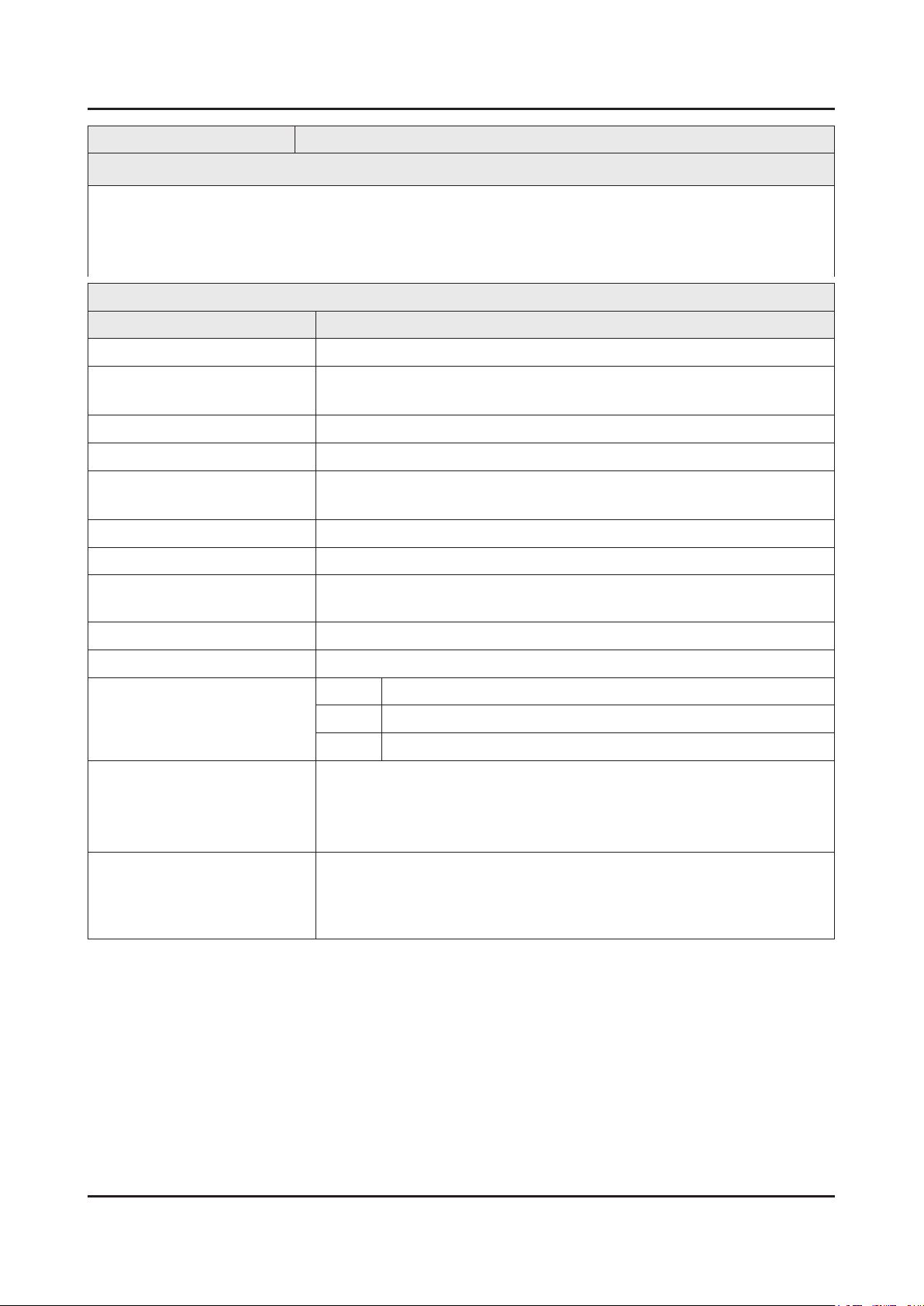
2-2. Detailed Specications
2-2-1. Model Comparison
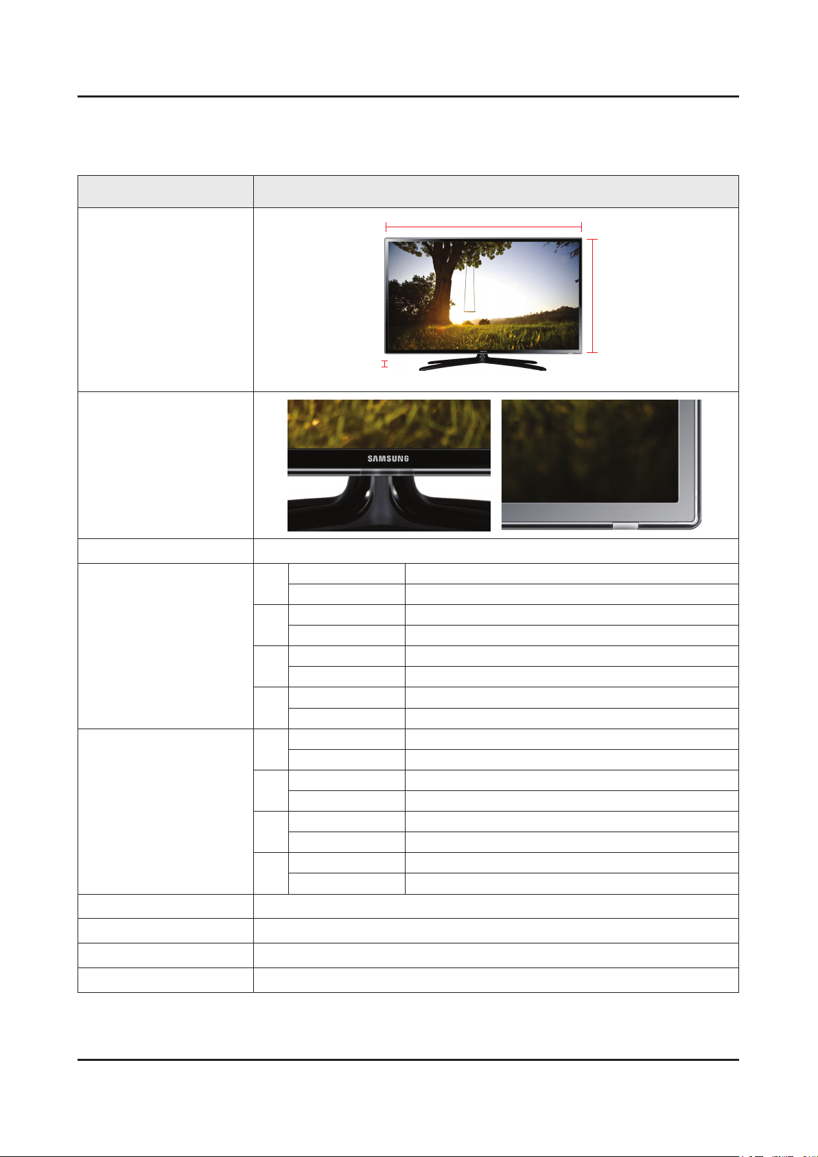
Model UE**F6100AW
W
Front View
D
Detail View
Front Color Black
32"
40"
Dimensions
(W x H x D)
46"
55"
32"
40"
Weight
46"
55"
Panel Type Black
Set with Stand 743.8 x 508.7 x 191.7 mm
Set without Stand 743.8 x 441.7 x 49.5 mm
Set with Stand 934 x 617.4 x 235 mm
Set without Stand 934 x 548.6 x 49.6 mm
Set with Stand 1065.4 x 697.3 x 235 mm
Set without Stand 1065.4 x 622.5 x 49.6 mm
Set with Stand 1256 x 798.6 x 235 mm
Set without Stand 1256 x 729.3 x 19.2 mm
Set with Stand 5.8 kg
Set without Stand 5.1 kg
Set with Stand 10.4 kg
Set without Stand 8.7 kg
Set with Stand 13.1 kg
Set without Stand 11.5 kg
Set with Stand 18.3 kg
Set without Stand 16.9 kg
* W : Width H : High D : Depth
H
Internal Memory 4 G
DDR 1 G
Feature 3D / USB HID / DLNA / Full Browsing / Miracast
2-8
2. Product specications
2-2-2. Feature & Specications
Model UE32F6100AW
Feature
Digital-TV, RF, 2-HDMI, 1-Component,1-A/V, 1-USB2.0(Media Play)•
PIP(in HDMI 1, 2 Component and Sub picture is available only in TV mode(DTV/ATV))•
• CMR (Clear Motion Rate) : 200
Dolby Digital Plus Pulse, DTS Premium Sound 5.1, DTS Studio Sound•
Specications
Item Description
LCD Panel 32 inch FHD 120 Hz
Input Signal Frequency Horizontal : 31~80 kHz
Vertical : 56 ~ 75 Hz
Input Sync Signal H/V Separate, TTL, P. or N.
Display Colors 1.07 B
Maximum Resolution Horizontal : 1920 Pixels
Vertical : 1080 Pixels
Input Signal Analog 0.7 Vp-p ± 5% positive at 75Ω, internally terminated
Maximum Pixel Clock Rate 138 MHz
Active Display (H x V)*
* Horizontal x Vertical
AC Power Voltage & Frequency AC220-240 V ~ 50/60 Hz
Power Consumption 92 W (Under 0.3 W, Stand by)
TV System Tunning Frequency Synthesize (Refer to detailed Frequency Table)
Environmental Considerations Operating Temperature : 50˚F ~ 104˚F (10˚C ~ 40˚C)
Audio Specications MAX Internal Audio Output Power : Each 10 W (Left/Right)
698.4 (H) X 392.85 (V) mm
System DVB-T/C/S2 (UK and Nordic : T2/C/S2), PAL, SECAM, NT4.4
Sound BK, DK, NICAM, MPEG1, Dolby Digital +
Operating Humidity : 10% ~ 80%, non-condensing
Storage Temperature : -13˚F ~ 113˚F (-25˚C ~ 45˚C)
Storage Humidity : 5% ~ 95%, non-condensing
Equalizer : 5 Band
Output Frequency : RF : 20 Hz ~ 15.4 kHz
AV/Componet/HDMI : 20 Hz ~ 20 kHz

2-9
2. Product specications
Model UE40F6100AW
Feature
Digital-TV, RF, 2-HDMI, 1-Component,1-A/V, 1-USB2.0(Media Play)•
PIP(in HDMI 1, 2 Component and Sub picture is available only in TV mode(DTV/ATV))•
• CMR (Clear Motion Rate) : 200
Dolby Digital Plus Pulse, DTS Premium Sound 5.1, DTS Studio Sound•
Specications
Item Description
LCD Panel 40 inch FHD 120 Hz
Input Signal Frequency Horizontal : 31~80 kHz
Vertical : 56 ~ 75 Hz
Input Sync Signal H/V Separate, TTL, P. or N.
Display Colors 1.07 B
Maximum Resolution Horizontal : 1920 Pixels
Vertical : 1080 Pixels
Input Signal Analog 0.7 Vp-p ± 5% positive at 75Ω, internally terminated
Maximum Pixel Clock Rate 138 MHz
Active Display (H x V)*
* Horizontal x Vertical
AC Power Voltage & Frequency AC220-240 V ~ 50/60 Hz
Power Consumption 122 W (Under 0.3 W, Stand by)
TV System Tunning Frequency Synthesize (Refer to detailed Frequency Table)
Environmental Considerations Operating Temperature : 50˚F ~ 104˚F (10˚C ~ 40˚C)
Audio Specications MAX Internal Audio Output Power : Each 10 W (Left/Right)
885.6 H x 498.15 V mm
System DVB-T/C/S2 (UK and Nordic : T2/C/S2), PAL, SECAM, NT4.4
Sound BK, DK, NICAM, MPEG1, Dolby Digital +
Operating Humidity : 10% ~ 80%, non-condensing
Storage Temperature : -13˚F ~ 113˚F (-25˚C ~ 45˚C)
Storage Humidity : 5% ~ 95%, non-condensing
Equalizer : 5 Band
Output Frequency : RF : 20 Hz ~ 15.4 kHz
AV/Componet/HDMI : 20 Hz ~ 20 kHz

2-10
2. Product specications
Model UE46F6100AW
Feature
Digital-TV, RF, 2-HDMI, 1-Component,1-A/V, 1-USB2.0(Media Play)•
PIP(in HDMI 1, 2 Component and Sub picture is available only in TV mode(DTV/ATV))•
• CMR (Clear Motion Rate) : 200
Dolby Digital Plus Pulse, DTS Premium Sound 5.1, DTS Studio Sound•
Specications
Item Description
LCD Panel 46 inch FHD 120 Hz
Input Signal Frequency Horizontal : 31~80 kHz
Vertical : 56 ~ 75 Hz
Input Sync Signal H/V Separate, TTL, P. or N.
Display Colors 1.07 B
Maximum Resolution Horizontal : 1920 Pixels
Vertical : 1080 Pixels
Input Signal Analog 0.7 Vp-p ± 5% positive at 75Ω, internally terminated
Maximum Pixel Clock Rate 138 MHz
Active Display (H x V)*
* Horizontal x Vertical
AC Power Voltage & Frequency AC220-240 V ~ 50/60 Hz
Power Consumption 128 W (Under 0.3 W, Stand by)
TV System Tunning Frequency Synthesize (Refer to detailed Frequency Table)
Environmental Considerations Operating Temperature : 50˚F ~ 104˚F (10˚C ~ 40˚C)
Audio Specications MAX Internal Audio Output Power : Each 10 W (Left/Right)
1018.08 H x 572.67 V mm
System DVB-T/C/S2 (UK and Nordic : T2/C/S2), PAL, SECAM, NT4.4
Sound BK, DK, NICAM, MPEG1, Dolby Digital +
Operating Humidity : 10% ~ 80%, non-condensing
Storage Temperature : -13˚F ~ 113˚F (-25˚C ~ 45˚C)
Storage Humidity : 5% ~ 95%, non-condensing
Equalizer : 5 Band
Output Frequency : RF : 20 Hz ~ 15.4 kHz
AV/Componet/HDMI : 20 Hz ~ 20 kHz
2-11
2. Product specications
Model UE55F6100AW
Feature
Digital-TV, RF, 2-HDMI, 1-Component,1-A/V, 1-USB2.0(Media Play)•
PIP(in HDMI 1, 2 Component and Sub picture is available only in TV mode(DTV/ATV))•
• CMR (Clear Motion Rate) : 200
Dolby Digital Plus Pulse, DTS Premium Sound 5.1, DTS Studio Sound•
Specications
Item Description
LCD Panel 55 inch FHD 120 Hz
Input Signal Frequency Horizontal : 31~80 kHz
Vertical : 56 ~ 75 Hz
Input Sync Signal H/V Separate, TTL, P. or N.
Display Colors 1.07 B
Maximum Resolution Horizontal : 1920 Pixels
Vertical : 1080 Pixels
Input Signal Analog 0.7 Vp-p ± 5% positive at 75Ω, internally terminated
Maximum Pixel Clock Rate 138 MHz
Active Display (H x V)*
* Horizontal x Vertical
AC Power Voltage & Frequency AC220-240 V ~ 50/60 Hz
Power Consumption 128 W (Under 0.3 W, Stand by)
TV System Tunning Frequency Synthesize (Refer to detailed Frequency Table)
Environmental Considerations Operating Temperature : 50˚F ~ 104˚F (10˚C ~ 40˚C)
Audio Specications MAX Internal Audio Output Power : Each 10 W (Left/Right)
1209.6 (H) X 680.4 (V) mm
System DVB-T/C/S2 (UK and Nordic : T2/C/S2), PAL, SECAM, NT4.4
Sound BK, DK, NICAM, MPEG1, Dolby Digital +
Operating Humidity : 10% ~ 80%, non-condensing
Storage Temperature : -13˚F ~ 113˚F (-25˚C ~ 45˚C)
Storage Humidity : 5% ~ 95%, non-condensing
Equalizer : 5 Band
Output Frequency : RF : 20 Hz ~ 15.4 kHz
AV/Componet/HDMI : 20 Hz ~ 20 kHz
2-12
2. Product specications
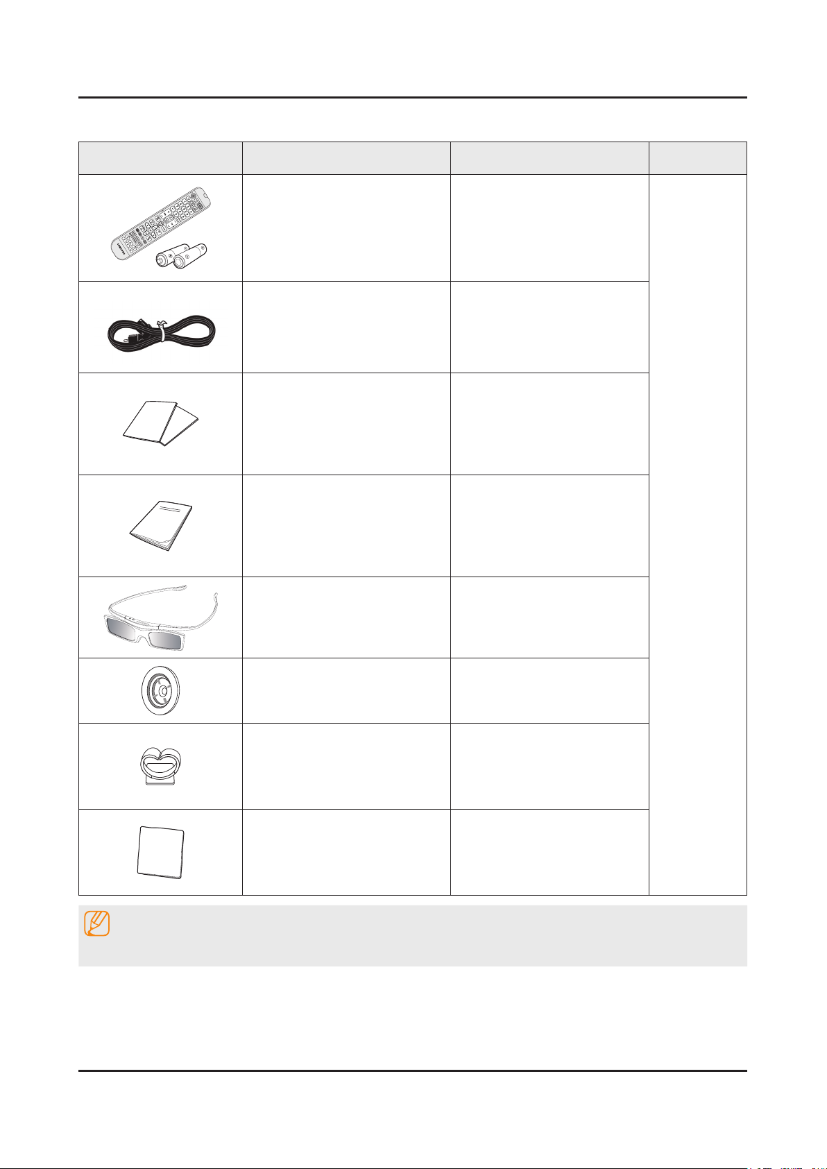
2-3. Accessories
Product Description Code. No Remark
Remote Control
Batteries (AAA x 2)
Power Cord 3903-000849
Warranty Card / Regulatory Guide BN68-03548J / BN68-04972A
User Manual BN68-04906C
3D Active Glasses
(for 40" models and above)
AA59-00743A
(4301-000121)
BN96-25614A
Holder-Ring BN61-07295A
Holder-Wire Stand BN61-08370A
Cloth-clean BN63-01798B
NOTE
The part code for some accessories may differ depending on your region.
2-13
2. Product specications
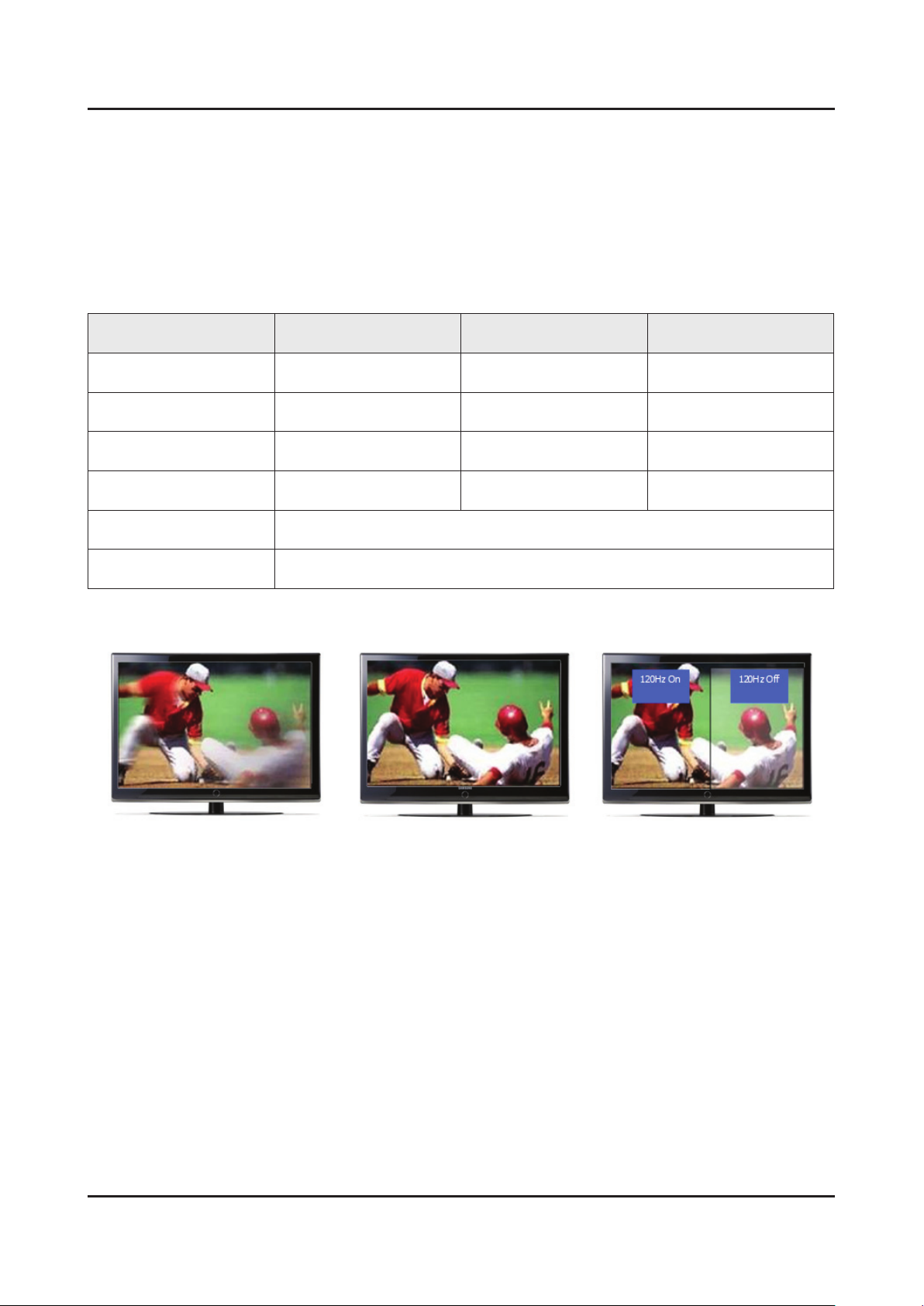
2-4. Viewing the Functions
2-4-1. Auto Motion Plus 120 Hz
Function Naming
120 Hz FRC + MJC : Auto Motion Plus 120 Hz -
Detail Specications
Function (OSD) 120 Hz FRC
Off
Clear
Standard
Smooth
Custom
Demo
(repeat)
(interpolation)
(interpolation)
(interpolation)
120Hz Motion Enhancement
Off
Off
ON
ON
ON
Judder reduction
(only 24p source)
Off Off
Off High
Medium Medium
High High
Level variable
(0~10)
Demo
(Standard / Off)
Blur reduction
Off Low / Mudium / High Demo
2-14
2. Product specications
2-4-2. Supported Formats
Supported Subtitle Formats
Exterminal
Name File Extension
MPEG-4 Timed text Timed text .ttxt
SAMI .smi
SubRip .srt
SubViewer .sub
Micro DVD .sub or .txt
SubStation Alpha .ssa
Advanced SubStation Alpha .ass
Powerdivx .psb
Internal
Name File Extension
Xsub AVI
SubStation Alpha MKV
Advanced SubStation Alpha MKV
SubRip MKV
MPEG-4 Timed text MP4
Supported Music File Formats
File Extension Type Codec Comments
*.mp3 MPEG MPEG1 Audio Layer 3
*.m4a
MPEG4 AAC*.mpa
*.aac
*.ac FLAC FLAC Supports up to 2 channel
*.ogg OGG Vorbis Supports up to 2 channel
WMA 10 Pro supports up to 5.1
*.wma WMA WMA
*.wav wav wav
*.mid
*.midi
*.ape ape ape
midi midi type 0, type 1 are supported.
channel. WMA lossless audio is
not supported. Supports up to M2
prole (except LBR mode)
2-15
2. Product specications
Supported Video Formats
File
Extension
*.avi
*.mkv
*.asf
*.wmv
*.mp4
*.3gp
*.vro
*.mpg
*.mpeg
*.ts
*.tp
*.trp
*.mov
*.v
*.vob
*.svi
Container Video Codec Resolution
Divx 3.11 / 4 / 5 / 6
1920 x
1080
1280 x 720
1920x1080
AVI
MKV
ASF
MP4
3GP
MOV
FLV
VRO
VOB
PS
TS
SVAF
MPEG4 SP/ASP
H.264 BP/MP/HP
Motion JPEG 640 x 480
Microsoft MPEG-4 v3
Window Media Video
v7,v8
Window Media Video v9
MPEG2
Frame rate
(fps)
6~30
Bit rate
(Mbps)
30
8
30
Audio Codec
AC3
LPCM
ADPCM(IMA,
MS)
AAC
HE-AAC
WMA
DD+
MPEG(MP3)
G.711(A-Law,
μ-Law)
*.m2ts
*.mts
*.divx
*.webm WebM VP8 1920 x1080 20 Vorbis
MPEG1
MVC
640 x 480
VP6 6~30 4
24/25/30 60
Other Restrictions
Codecs may not function properly if there is a problem with the content data. Video content does not play or does not
play correctly if there is an error in the content or container. "Sound or video may not work if they have standard bit rates/
frame rates above the TV’s compatibility ratings." If the Index Table is wrong, the Seek (Jump) function does not work.
"When playing video over a network connection, the video may not play smoothly because of data transmission speeds."
Some USB/digital camera devices may not be compatible with the player.
Video Decorders
Supports up to H.264, Level 4.1 (does not support FMO/ASO/RS)•
VC1 AP L4 is not supported.•
All video codecs excluding WMV v7, v8, MSMPEG4 v3, MVC, and VP6:•
Below 1280 x 720: 60 frame max -
Above 1280 x 720: 30 frame max -
GMC is not supported.•
Supports SVAF top/bottom and left/right only.•
Supports Blu-ray/DVD MVC specs only.•

2-16
2. Product specications
Audio Decorders
WMA 10 Pro supports up to 5.1 channels. Supports up to M2 prole. (Excluding M0 LBR mode)•
WMA lossless audio is not supported.•
Vorbis is supported for up to 2 channels.•
DD+ is supported for up to 5.1 channels.•
2-17
2. Product specications
2-4-3. 3D Display
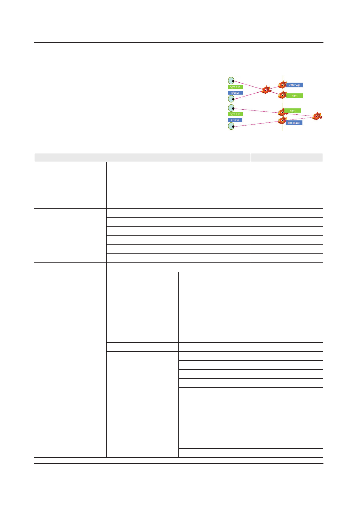
What is 3D Display?
This mode is to enables users to view images on the TV/Monitor in 3D by
receiving the video signal in 3D format from sources such as 3D games
and titles. The human brain constructs a 3 dimensional image from the
two images entering both eyes. The depth of a 3 dimensional images is
determined by the horizontal difference between the images from both
the left and right eyes. 3D is displaysed two images alternately on screen
equivalent to left and right at TV, and embodies by doing to see each
relevant image in left eye and right eye through shutter glasses.
3D Function of Model Series
LCD / LED / PDP TV LED
Sub Items 120 Hz
Platform (Main) X12
Items
Platform (FRC / Formatter)
2D → 3D Coversion O
3D → 2D O
3D Feature
FRC Feature Auto Motion Plus O
3D Input Format
3D Perspective O
3D Depth O
Auto View (Auto Format Detection) X
3D Optimize O
ATV / AV, PC 2D → 3D O
Component
HDMI
HDMI (PC / DVI) LL, VS, Check ker BD, FS X
HDMI (PC / DVI)
DTV
2D → 3D O
SS, TB O
2D → 3D O
SS, TB O
FP 1080P 24 / 25 / 30
FP 720P 50 / 60
FP 1080i 50 / 60
2D → 3D O
SS, TB O
MPO O
SVAF IES (SS, BT) O
MVC 1080P 24 / 25 /30
MVC 720P 50 / 60
MVC 1080i 50 / 60
MVC 720P 24 / 25 /30
2D → 3D O
SS, TB O
DVB_Phasel (SS, BT) O
ATSC_KR30 O
Fox-FT1 (SDC)
Fox-FT2 (AUO / CMI)
Echo-Fs (Sharp 3D)
NT7231 2 (Sharp 2D)
O
O
2. Product specications
Surpported 3D Resolutions
These specications apply to a display ratio of 16:9 only.
3D Format: L/R, T/B•
Resolution Frequency (Hz)
1280 x 720p 59.94 / 60
1920 x 1080i 59.94 / 60
1920 x 1080p 23.98 / 24 / 29.97 / 30 / 59.94 / 60
3D Format: Frame Packing•
Resolution Frequency (Hz)
1280 x 720p 59.94 / 60
1920 x 1080i 59.94 / 60
1920 x 1080p 23.98 / 24 / 29.97 / 30
Component•
Resolution Frequency (Hz)
1280 x 720p 59.94 / 60
1920 x 1080i 59.94 / 60
1920 x 1080p 23.98 / 24 / 29.97 / 30 / 59.94 / 60
Digital Channel•
Resolution Frequency (Hz)
1280 x 720p 59.94 / 60
1920 x 1080i 59.94 / 60
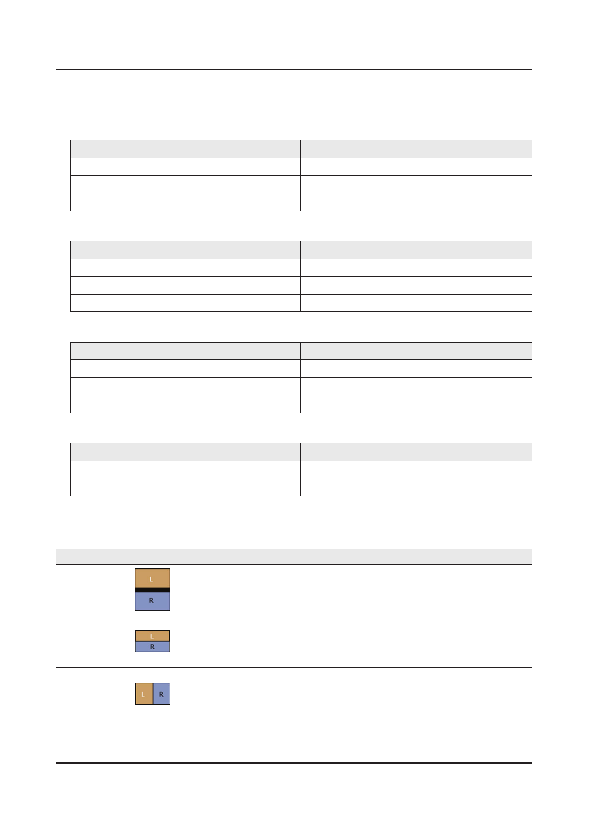
3D Format Test
3D Format : There are several 3D formats existing on how to merge Left and Right images.
Format Input images Test Method
Frame Packin
(HDMI 1.4)
Top & Bottom
Side by Side
2D → 3D
Able to test only by HDMI 1.4 BD Player or MSPG-4600MT(Master Device)
Using Format_test.bmp
Check in the PC(HDMI) source. PC resolution and format resolution must be same•
Wearing 3D glass, left eye sees only ‘L’ letter, right eye sees only ‘R’ letter (close •
your eyes one by one)
Using Format_test.bmp
Check in the PC(HDMI) source. PC resolution and format resolution must be same•
Wearing 3D glass, left eye sees only ‘L’ letter, right eye sees only ‘R’ letter (close •
your eyes one by one)
Check in the normal 2D source. Check not in the test pattern but in the actual video.
Left/Right black region will grow more and more as the depth goes higher.•
2-18
3. Disassembly and Reassemble
3. Disassembly and Reassembly
This section of the service manual describes the disassembly and reassembly procedures for the LED TV.
This LED TV contains electrostatically sensitive devices. Use caution when handling these components.
WARNING
3-1. Disassembly and Reassembly
Disconnect the LED TV from the power source before disassembly.1.
Follow these directions carefully; never use metal instruments to pry apart the cabinet.2.
CAUTION
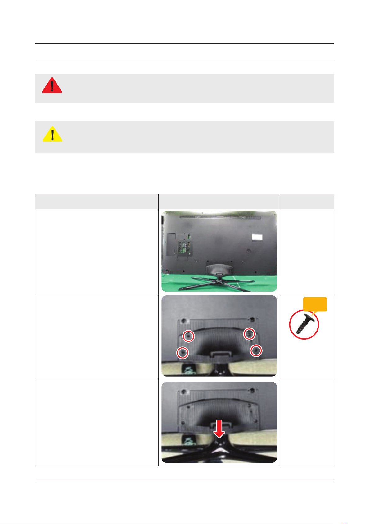
3-1-1. LED TV
32 / 40 / 46 Inches
Place TV face down on cushioned table.
If there is no additional coment, it is same for all inches.3.
Description Picture Description Screws
1
Remove 4 screws from the ASSY
2
GUIDE P-STAND.
Remove STAND.
3
Torque :
9~11Kgf.cm.
128~156psi
6003-001782
SCREW-MACHINE
M4.0, L12.0 BLK
3-1
3-2
3. Disassembly and Reassemble
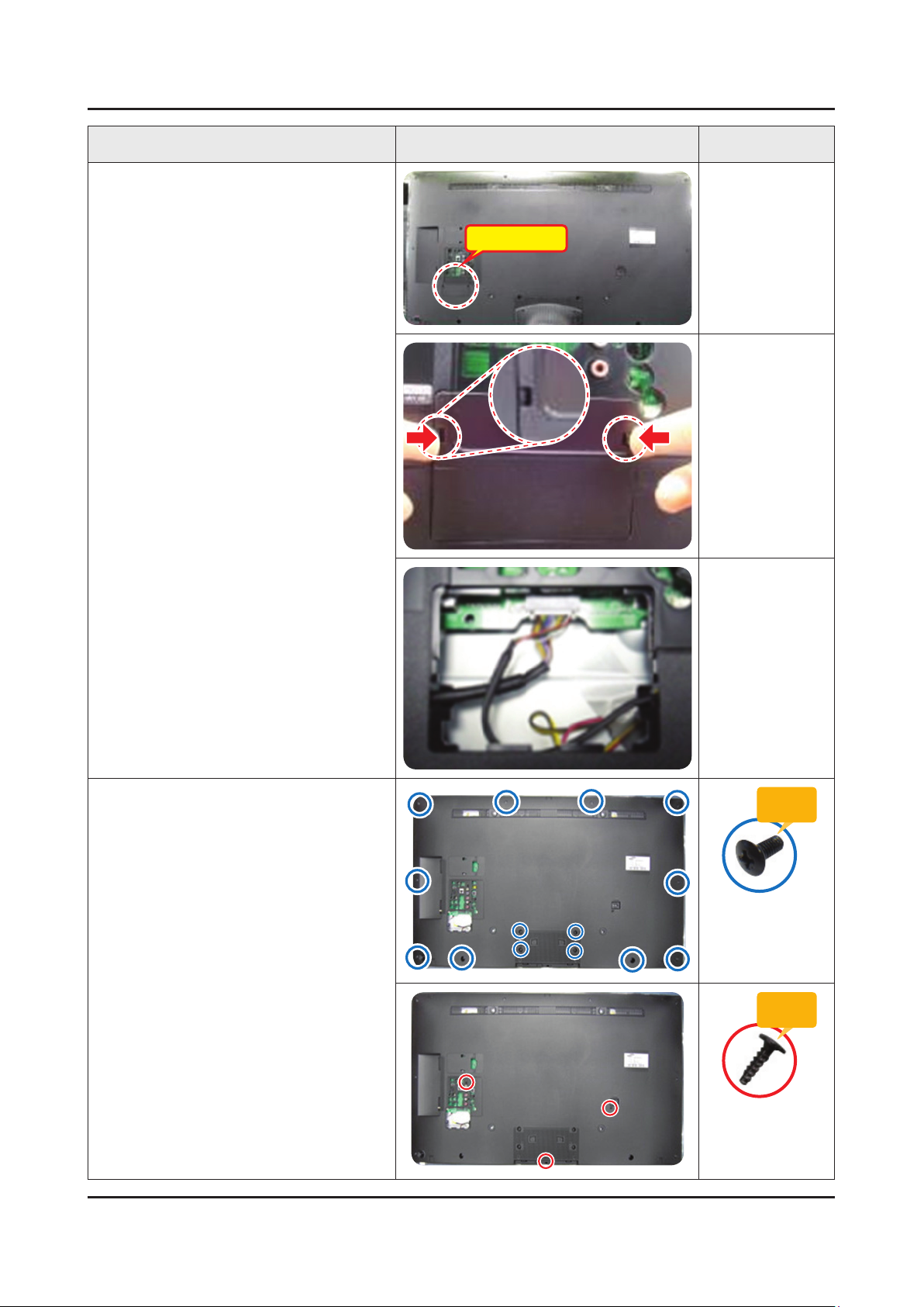
Description Picture Description Screws
Remove the COVER-JACK after push
4
the locking in both sides.
COVER-JACK
Remove screws of ASSY COVER
5
P-MIDDLE, REAR.
32 inch : 9 EA •
40 inch : 14 EA•
46 inch : 14 EA •
32 inch : 2 EA •
40 inch : 2 EA•
46 inch : 3 EA•
Torque :
7~8Kgf.cm.
100~113psi
6001-002755
SCREW-MACHINE
M3.0, L6.0 BLK
Torque :
9~11Kgf.cm.
128~156psi
6003-001782
SCREW-MACHINE
M4.0, L12.0 BLK
3-3
3. Disassembly and Reassemble
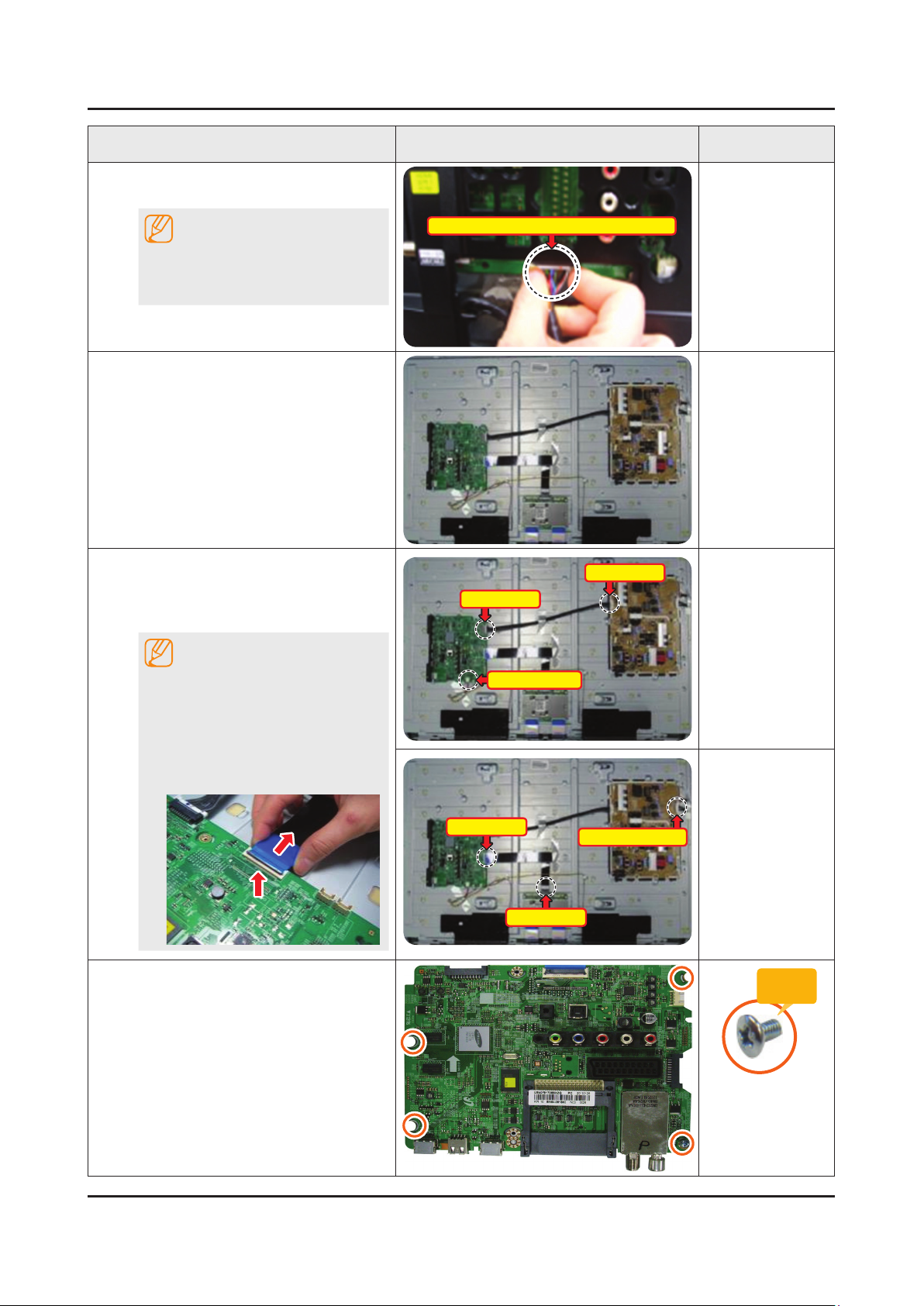
Description Picture Description Screws
Disconnect the ASSY BOARD P-JOG
6
SWITCH & IR Cable.
NOTE
First remove the cable before you
remove the ASSY COVER P-MIDDLE,
REAR.
Remove the ASSY COVER P-MIDDLE,
7
REAR.
Remove the Power Cables and Speaker
8
Cables.
Remove the LVDS Cable and Panel
Drive Cable.
NOTE
ASSY BOARD P-JOG SWITCH & IR Cable
Power Cable
Power Cable
Applied to Double locking.
Flip up the locking tab on top of the 1.
connector.
Squeeze the edge of the connector 2.
to release the second tab lock and
gently pull the connector away.
Remove the screws of ASSY PCB
9
MAIN.
Speaker Cable
LVDS Cable
LVDS Cable
Panel Drive Cable
Torque :
7~8Kgf.cm.
100~113psi
6001-002756
SCREW-MACHINE
M3.0, L6.0 WHT
3-4
3. Disassembly and Reassemble
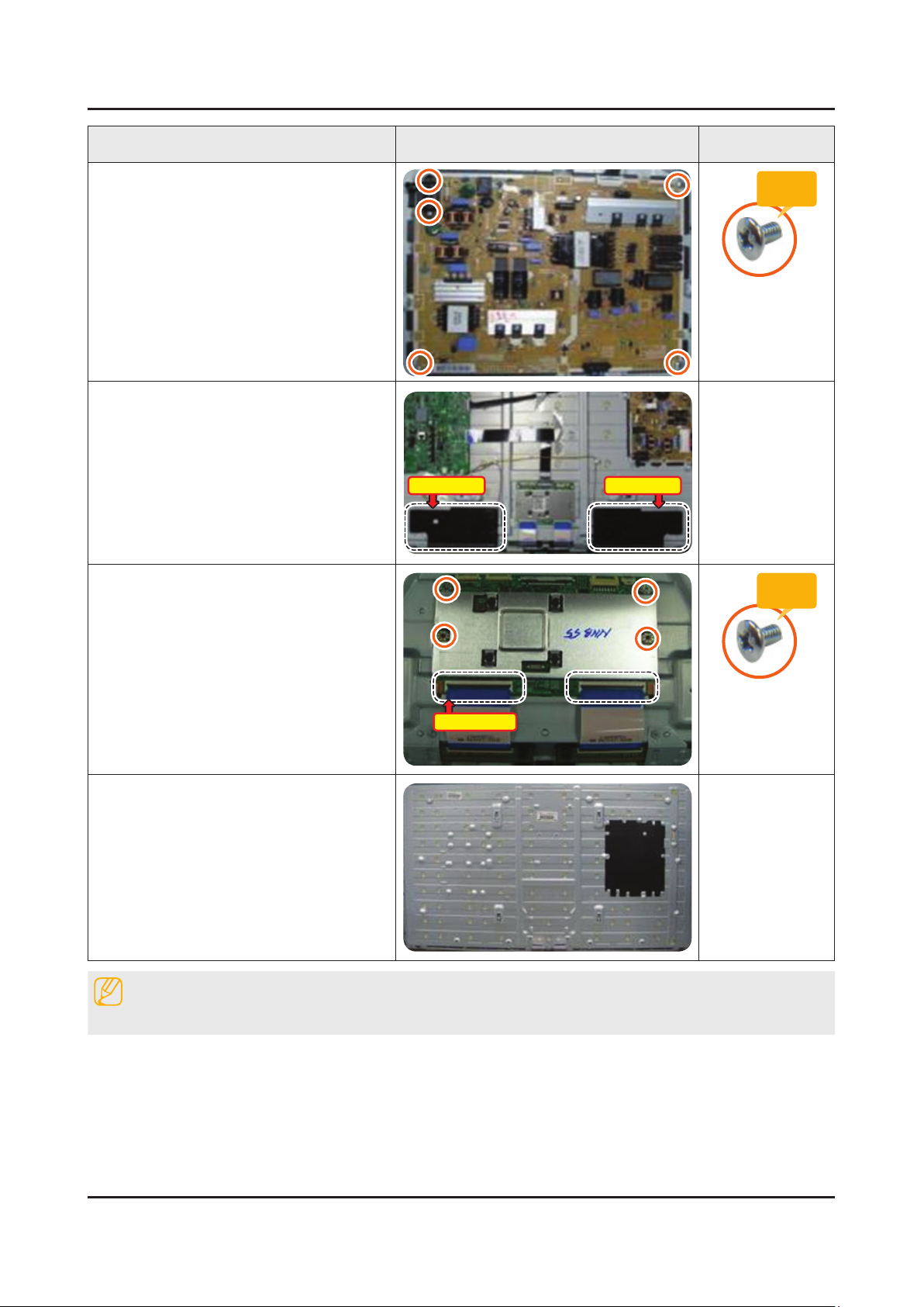
Description Picture Description Screws
Remove the screws of DC VSS-LED TV
10
PD BD.
Remove the ASSY SPEAKER (L/R).
11
Remove the 4 screws of ASSY T CON
12
and unlock the locking of T CON Cable.
Speakers(L) Speakers(R)
Torque :
7~8Kgf.cm.
100~113psi
6001-002756
SCREW-MACHINE
M3.0, L6.0 WHT
Torque :
7~8Kgf.cm.
100~113psi
T CON Cable
Completed disassembly.
13
Reassembly procedures are in the reverse order of disassembly procedures.
Panel.•
NOTE
6001-002756
SCREW-MACHINE
M3.0, L6.0 WHT
 Loading...