

Page 1

LFD DISPLAY
User Manual
UD46C UD55C
The color and the appearance may differ depending on the
product, and the specifications are subject to change without
prior notice to improve the performance.
BN46-00332A-06
Page 2

Table of contents
Before Using the Product
Copyright 6
Safety Precautions 7
Symbols 7
Cleaning 7
Storage 8
Electricity and Safety 8
Installation 9
Operation 11
Preparations
Checking the Contents 14
Removing the Packaging 14
Checking the Components 15
Parts 17
External sensor KIT 17
Reverse Side 18
Attaching the holders 19
Anti-theft Lock 19
Remote Control 20
Connection Using an IR Stereo Cable (sold
separately) 23
Before Installing the Product (Installation
Guide) 24
Tilting Angle and Rotation 24
Ventilation 24
Dimensions 25
Installing the Wall Mount 26
Preparing before installing Wall-Mount 26
Installing the Wall Mount Kit 26
Wall Mount Kit Specifications (VESA) 27
Remote Control (RS232C) 28
Cable Connection 28
Connection 31
Control Codes 32
Connecting and Using a Source
Device
Before Connecting 41
Pre-connection Checkpoints 41
Connecting to a PC 42
Connection using the D-SUB cable (Analog type) 42
Connection using a DVI cable (Digital type) 42
Connection Using an HDMI-DVI Cable 43
Connection Using an HDMI Cable 43
Connection Using an DP Cable 43
Changing the Resolution 44
Changing the Resolution on Windows XP 44
Changing the Resolution on Windows Vista 44
Changing the Resolution on Windows 7 45
Changing the Resolution on Windows 8 45
Connecting to a Video Device 46
Connection Using the AV Cable 46
Connection Using the component Cable 46
Connection Using an HDMI-DVI Cable 47
Connection Using an HDMI Cable 47
Connecting to an Audio System 48
Connecting an External Monitor 48
Connecting the network box (Sold separately) 49
MagicInfo 49
Source 51
Using MDC
Configuring Settings for Multi Control 52
Configuring settings for Multi Control 52
MDC Program Installation/Uninstallation 53
Installation 53
Uninstallation 53
What is MDC? 54
Connecting to MDC 54
Connection Management 57
User Login 58
Auto Set ID 59
Cloning 60
Command Retry 61
Getting Started with MDC 62
Main Screen Layout 63
Menus 63
Screen Adjustment 65
Advanced features 68
2
Page 3

Table of contents
Sound Adjustment 70
System Setup 70
Tool Settings 79
Other Functions 82
Group Management 83
Schedule Management 85
Troubleshooting Guide 87
Screen Adjustment
Picture Mode 89
If the input source is PC, DVI or DisplayPort 89
If the input source is AV, Component, HDMI1,
89
HDMI2
Backlight / Contrast / Brightness / Sharpness /
Color / Tint (G/R)
Screen Adjustment 91
Picture Size 91
Position 93
Zoom/Position 93
PC Screen Adjustment 94
Resolution Select 94
Auto Adjustment 95
Rotation 95
Aspect Ratio 96
Advanced Settings 97
Dynamic Contrast 98
90
Black Tone 98
Flesh Tone 98
RGB Only Mode 98
Color Space 98
White Balance 99
10p White Balance 99
Gamma 99
Expert Pattern 100
Motion Lighting 100
Picture Options 101
Color Tone 102
Color Temp. 102
Digital Noise Filter 102
MPEG Noise Filter 102
HDMI Black Level 102
Film Mode 103
Calibrated Value 103
Dynamic Backlight 103
Reset Picture 103
Network
Network Settings 104
Connecting to a Wired Network 104
Wired Network Settings 105
Connecting to a Wireless Network 106
Wireless Network Setting 107
WPS(PBC) 108
Network Status 109
Wi-Fi Direct 109
Soft AP 110
AllShare Settings 110
Device Name 110
System
Multi Control 111
Configuring settings for Multi Control 111
Time 112
Clock Set 112
Sleep Timer 112
On Timer 113
Off Timer 114
Holiday Management 114
Menu Language 115
Rotate Menu 115
Eco Solution 116
Energy Saving 116
Eco Sensor 116
No Signal Power Off 116
Auto Power Off 116
Caption 117
Caption 117
3
Page 4

Table of contents
Caption Mode 117
Digital Caption Options 117
Security 118
Safety Lock 118
Button Lock 118
Change PIN 118
PIP 119
Auto Protection Time 120
Screen Burn Protection 121
Pixel Shift 121
Timer 122
Immediate Display 123
Side Gray 123
Ticker 123
Video Wall 124
Video Wall 124
Format 124
Horizontal 124
Vertical 125
Screen Position 125
Source AutoSwitch Settings 126
Source AutoSwitch 126
Primary Source Recovery 126
Primary Source 126
Secondary Source 126
General 127
Max. Power Saving 127
Game Mode 127
BD Wise 127
Menu Transparency 127
Sound Feedback 128
Auto Power 128
Standby Control 128
Lamp Schedule 129
OSD Display 129
Power On Adjustment 129
Repeat Mode 129
Anynet+ (HDMI-CEC) 130
Anynet+ (HDMI-CEC) 130
Auto Turn Off 131
DivX® Video On Demand 134
Player Mode 134
Magic Clone 135
Reset System 135
Reset All 136
PC Module Power 136
Synced Power-On 136
Synced Power-Off 136
Support
Software Update 137
By USB 137
Alternative Software 138
Contact Samsung 138
Contents Home 139
MagicInfo Lite 139
MagicInfo Premium S 139
MagicInfo Videowall S 139
AllShare Play 140
Source 140
AllShare Play
What is AllShare Play? 141
Read the following before using AllShare Play with
a USB device 141
Using a USB device 143
Connecting to a PC over a network 144
Using the AllShare Play features 145
Using the Basic AllShare Play Features 146
Sorting the file lists 146
Playing Selected Files 147
Copying Files 147
Creating a Playlist 147
My List 148
My List options 148
Videos 149
Playing a Video 149
Photos 150
Viewing a Photo (or Slide Show) 150
Music 151
Playing Music 151
4
Page 5

Table of contents
Videos / Photos / Music Play Option menu 152
Supported Subtitle and AllShare Play file
formats 154
Subtitle 154
Supported image resolutions 154
Supported music file formats 155
Supported Video Formats 155
MagicInfo Lite
File Formats Compatible with MagicInfo Lite
157
Player
Read before using MagicInfo Lite Player 157
Approving a connected device from the server
162
MagicInfo Lite
MagicInfo Lite Player 164
Local Schedule Manager 167
Content Manager 174
Settings 176
When Content is Running 178
164
Approving a connected device from the server
186
MagicInfo Premium S
MagicInfo Premium S Player 188
Local Schedule Manager 191
Template Manager 198
Content Manager 201
Settings 203
When Content is Running 205
188
MagicInfo Videowall S
File Formats Compatible with MagicInfo
Videowall S Player
Read before using MagicInfo Videowall S Player 207
MagicInfo Videowall S 210
Settings 210
When Content is Running 211
207
Troubleshooting Guide
Specifications
General 221
PowerSaver 224
Preset Timing Modes 225
Appendix
Contact SAMSUNG WORLD WIDE 227
Responsibility for the Pay Service (Cost to
Customers) 236
Not a product defect 236
A Product damage caused by customer's fault 236
Others 236
Optimum Picture Quality and Afterimage Burnin Prevention 237
Optimum Picture Quality 237
Prevention of Afterimage Burn-in 238
License 240
Terminology 241
MagicInfo Premium S
File Formats Compatible with MagicInfo
Premium S Player
Read before using MagicInfo Premium S Player 180
180
Requirements Before Contacting Samsung
Customer Service Center 212
Testing the Product 212
Checking the Resolution and Frequency 212
Check the followings. 213
Q & A 219
5
Page 6

Chapter 01
Before Using the Product
Copyright
The contents of this manual are subject to change without notice to improve quality.
© 2013 Samsung Electronics
Samsung Electronics owns the copyright for this manual.
Use or reproduction of this manual in parts or entirety without the authorization of Samsung Electronics is prohibited.
Microsoft, Windows are registered trademarks of Microsoft Corporation.
VESA, DPM and DDC are registered trademarks of the Video Electronics Standards Association.
Ownership of all other trademarks is attributed to their due owner.
6
Page 7
Safety Precautions
Caution
RISK OF ELECTRIC SHOCK DO NOT OPEN
Caution : TO REDUCE THE RISK OF ELECTRIC SHOCK, DO NOT REMOVE COVER. (OR BACK)
THERE ARE NO USER SERVICEABLE PARTS INSIDE.
REFER ALL SERVICING TO QUALIFIED PERSONNEL.
This symbol indicates that high voltage is present inside.
It is dangerous to make any kind of contact with any internal part of this product.
This symbol alerts you that important literature concerning operation and maintenance has been
included with this product.
Symbols
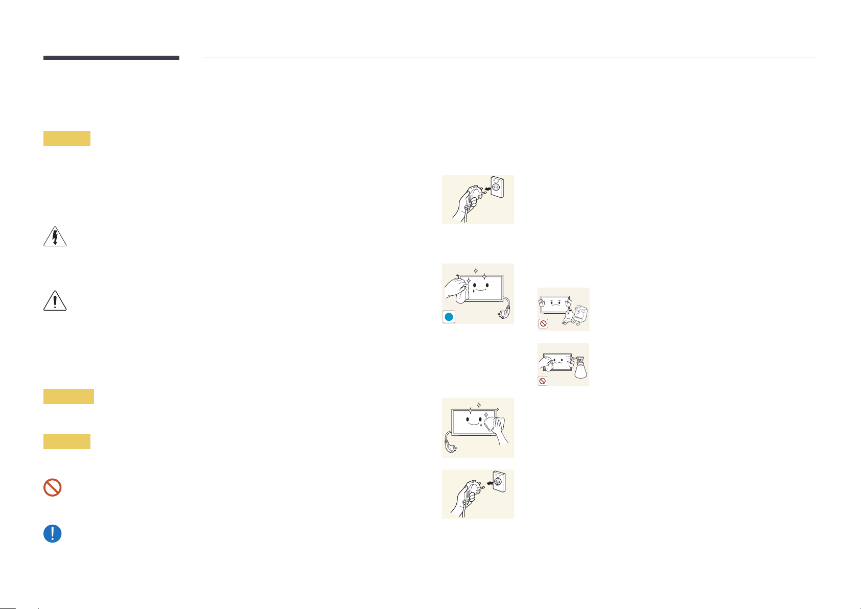
Cleaning
―
Exercise care when cleaning as the panel and exterior of advanced LCDs are easily scratched.
―
Take the following steps when cleaning.
―
The following images are for reference only. Real-life situations may differ from what is shown in the
images.
Power off the product and computer.
1
Disconnect the power cord from the product.
2
―
Hold the power cable by the plug and do not touch the cable with wet
hands. Otherwise, an electric shock may result.
Wipe the product with a clean, soft and dry cloth.
3
•
Do not use detergents that contain alcohol, solvent or
surface-active agents.
!
•
Do not spray water or detergent directly on the product.
Warning
A serious or fatal injury may result if instructions are not followed.
Caution
Personal injury or damage to properties may result if instructions are not followed.
Activities marked by this symbol are prohibited.
Instructions marked by this symbol must be followed.
Wet a soft and dry cloth in water and wring thoroughly to clean the
4
exterior of the product.
Connect the power cord to the product when cleaning is finished.
5
Power on the product and computer.
6
7
Page 8
Storage
High-glossy models can develop white stains on the surface if an ultrasonic wave humidifier is used
nearby.
―
Contact Customer Service Center if the inside of the product needs cleaning (service fee will be
charged).
Electricity and Safety
―
The following images are for reference only. Real-life situations may differ from what is shown in the
images.
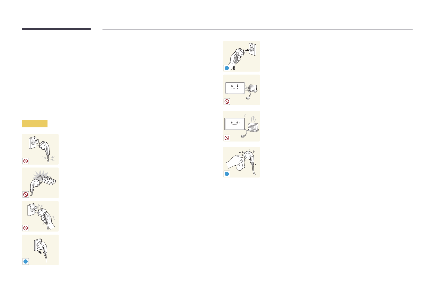
Warning
Do not use a damaged power cord or plug, or a loose power socket.
•
An electric shock or fire may result.
Do not use multiple products with a single power socket.
•
Overheated power sockets may cause a fire.
Connect the power plug to a grounded power socket (type 1 insulated
devices only).
•
An electric shock or injury may result.
!
Do not bend or pull the power cord with force. Be careful not to leave the
power cord under a heavy object.
•
Damage to the cord may result in a fire or electric shock.
Do not place the power cord or product near heat sources.
•
A fire or electric shock may result.
Clean any dust around the pins of the power plug or the power socket with
a dry cloth.
•
A fire may result.
!
Do not touch the power plug with wet hands. Otherwise, an electric shock
may result.
Insert the power plug all the way in so it is not loose.
•
An unsecure connection may cause a fire.
!
8
Page 9
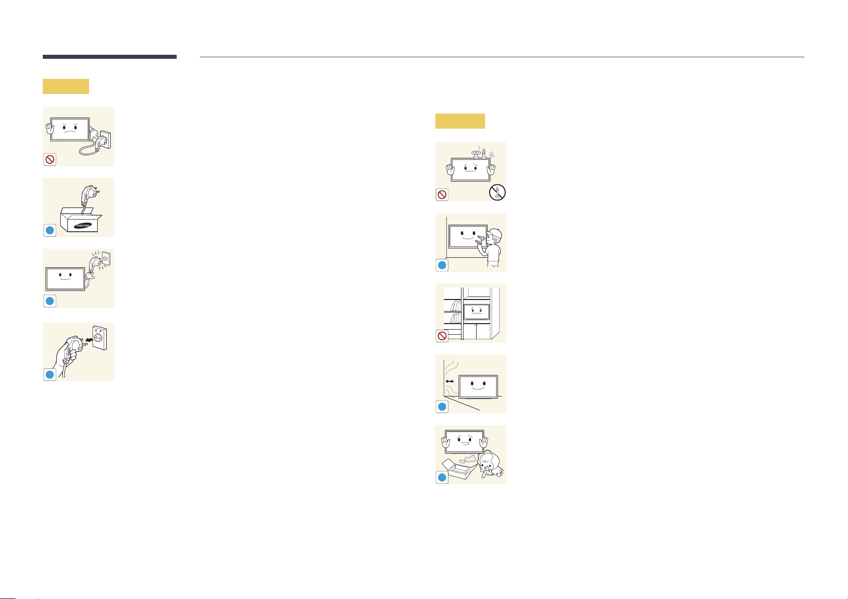
Caution
!
!
!
Do not disconnect the power cord while the product is being used.
•
The product may become damaged by an electric shock.
Only use the power cord provided with your product by Samsung. Do not
use the power cord with other products.
•
A fire or electric shock may result.
Keep the power socket where the power cord is connected unobstructed.
•
The power cord must be disconnected to cut off power to the product
when an issue occurs.
•
Note that the product is not completely powered down by using only
the power button on the remote.
Hold the plug when disconnecting the power cord from the power socket.
•
An electric shock or fire may result.
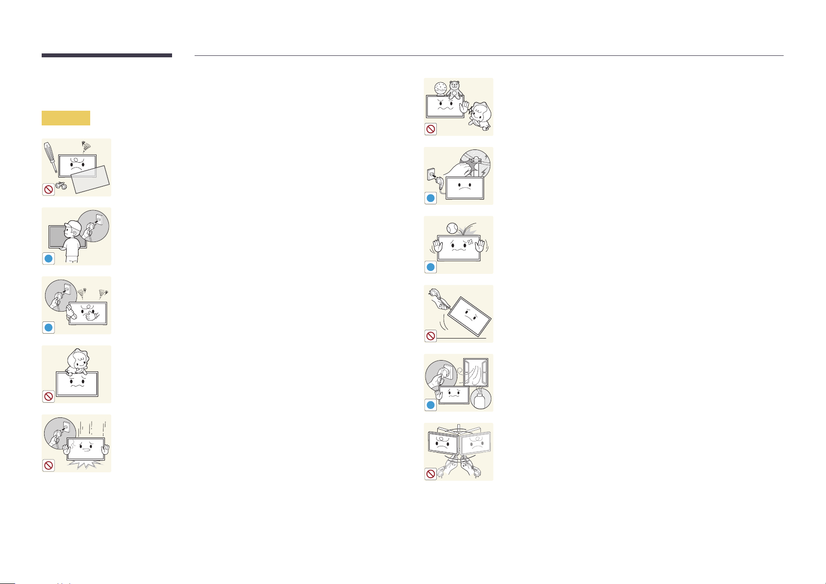
Installation
Warning
!
DO NOT PLACE CANDLES, INSECT REPELLANTS OR CIGARETTES ON TOP OF
THE PRODUCT. DO NOT INSTALL THE PRODUCT NEAR HEAT SOURCES.
•
A fire may result.
Have a technician install the wall-mount hanger.
•
Installation by an unqualified person can result in an injury.
•
Only use approved cabinets.
Do not install the product in poorly ventilated spaces such as a bookcase or
closet.
•
An increased internal temperature may cause a fire.
Install the product at least 10cm away from the wall to allow ventilation.
•
An increased internal temperature may cause a fire.
!
Keep the plastic packaging out of the reach of children.
•
Children may suffocate.
!
9
Page 10
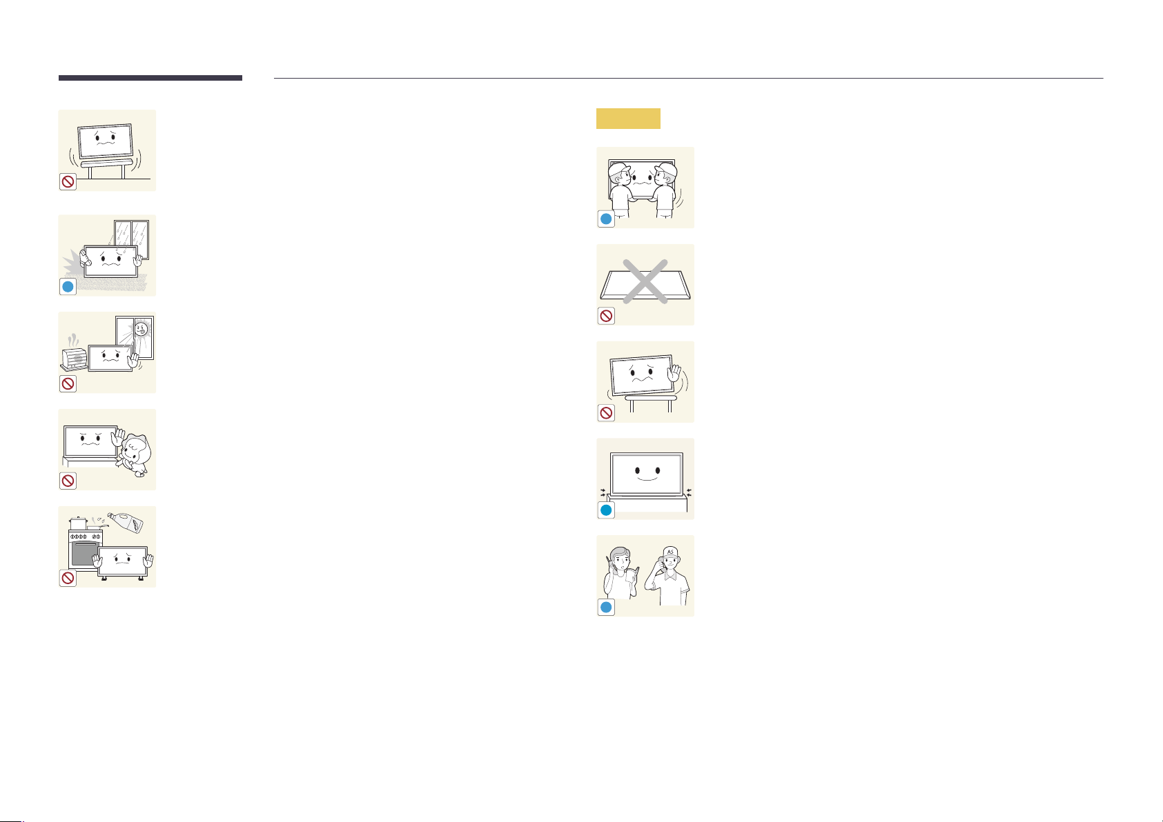
Do not install the product on an unstable or vibrating surface (insecure shelf,
sloped surface, etc.)
•
The product may fall and become damaged and/or cause an injury.
•
Using the product in an area with excess vibration may damage the
product or cause a fire.
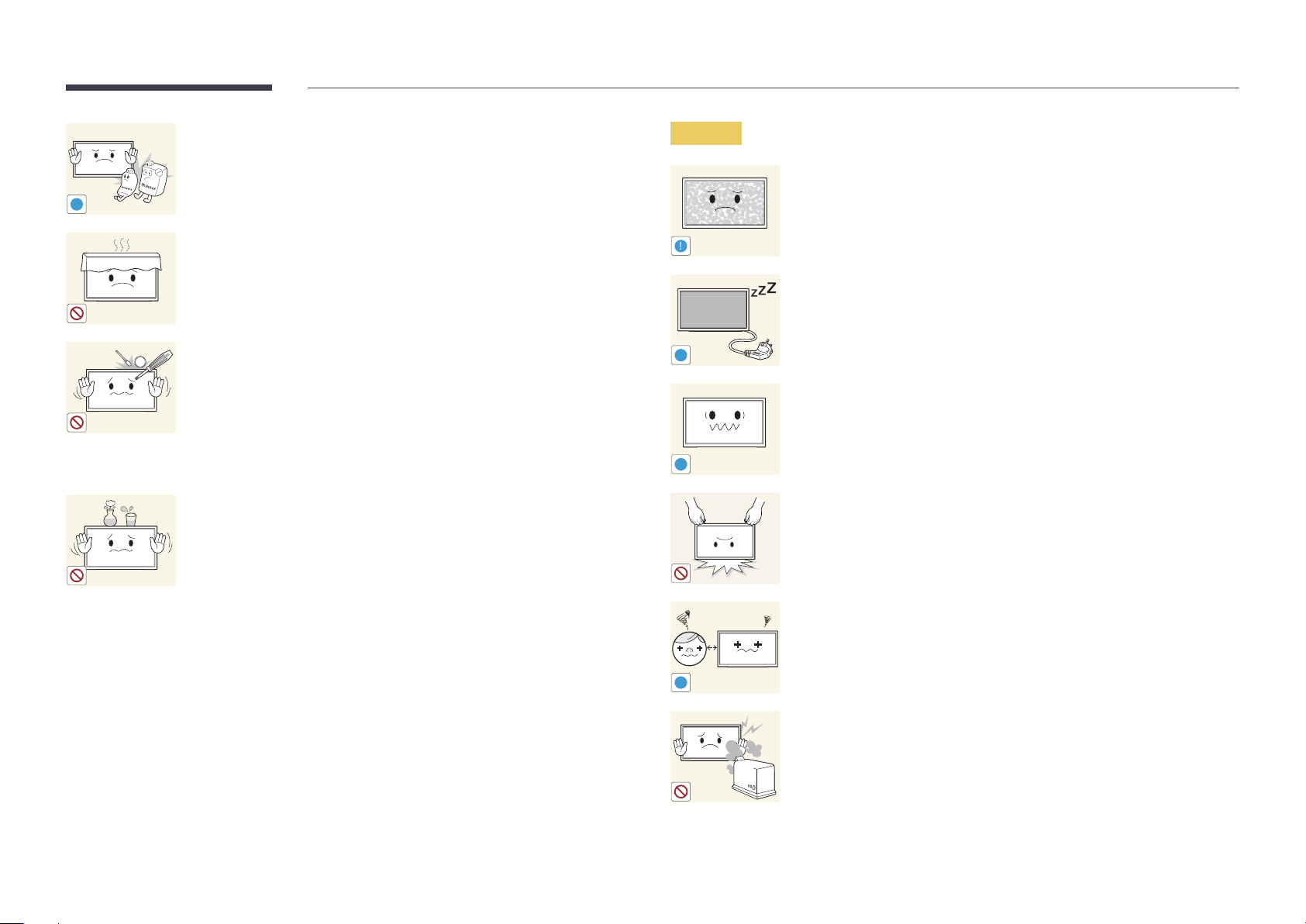
Caution
Do not drop the product while moving.
•
Product failure or personal injury may result.
Do not install the product in a vehicle or a place exposed to dust, moisture
!
(water drips, etc.), oil, or smoke.
•
A fire or electric shock may result.
!
Do not set down the product on its front.
•
The screen may become damaged.
Do not expose the product to direct sunlight, heat, or a hot object such as a
stove.
•
The product lifespan may be reduced or a fire may result.
Do not install the product within the reach of young children.
•
The product may fall and injure children.
•
As the front is heavy, install the product on a flat and stable surface.
Edible oil, such as soybean oil, can damage or deform the product. Do not
!
When installing the product on a cabinet or shelf, make sure that the
bottom edge of the front of the product is not protruding.
•
The product may fall and become damaged and/or cause an injury.
•
Install the product only on cabinets or shelves of the right size.
Set down the product gently.
•
Product failure or personal injury may result.
install the product in a kitchen or near a kitchen counter.
Installing the product in an unusual place (a place exposed to a lot of fine
particles, chemical substances or extreme temperatures, or an airport
or train station where the product should operate continuously for an
SAMSUNG
!
extended period of time) may seriously affect its performance.
•
Be sure to consult Samsung Customer Service Center if you want to
install the product at such a place.
10
Page 11
Operation
Warning
Do not leave heavy objects or items that children like (toys, sweets, etc.) on
top of the product.
•
The product or heavy objects may fall as children try to reach for the
toys or sweets resulting in a serious injury.
There is a high voltage inside the product. Never disassemble, repair or
modify the product yourself.
•
A fire or electric shock may result.
•
Contact Samsung Customer Service Center for repairs.
!
Before moving the product, turn off the power switch and disconnect the
power cable and all other connected cables.
•
Damage to the cord may result in a fire or electric shock.
!
If the product generates abnormal sounds, a burning smell or smoke,
disconnect the power cord immediately and contact Samsung Customer
Service Center.
•
An electric shock or fire may result.
!
Do not let children hang from the product or climb on top of it.
•
Children may become injured or seriously harmed.
If the product is dropped or the outer case is damaged, turn off the power
switch and disconnect the power cord. Then contact Samsung Customer
Service Center.
•
Continued use can result in a fire or electric shock.
!
!
GAS
During a lightning or thunderstorm, power off the product and remove the
power cable.
•
A fire or electric shock may result.
Do not drop objects on the product or apply impact.
•
A fire or electric shock may result.
Do not move the product by pulling the power cord or any cable.
•
Product failure, an electric shock or fire may result from a damaged
cable.
If a gas leakage is found, do not touch the product or power plug. Also,
ventilate the area immediately.
•
Sparks can cause an explosion or fire.
Do not lift or move the product by pulling the power cord or any cable.
•
Product failure, an electric shock or fire may result from a damaged
cable.
11
Page 12
Do not use or keep combustible spray or an inflammable substance near
the product.
•
An explosion or fire may result.
!
Ensure the vents are not blocked by tablecloths or curtains.
•
An increased internal temperature may cause a fire.
100
Do not insert metallic objects (chopsticks, coins, hairpins, etc) or objects
that burn easily (paper, matches, etc) into the product (via the vent or input/
output ports, etc).
•
Be sure to power off the product and disconnect the power cord
when water or other foreign substances have entered the product.
Then contact Samsung Customer Service Center.
•
Product failure, an electric shock or fire may result.
Caution
!
-_-
!
!
Leaving the screen fixed on a stationary image for an extended period of
time may cause afterimage burn-in or defective pixels.
•
Activate power-saving mode or a moving-picture screen saver if you
will not be using the product for an extended period of time.
Disconnect the power cord from the power socket if you do not plan on
using the product for an extended period of time (vacation, etc).
•
Dust accumulation combined with heat can cause a fire, electric shock
or electric leakage.
Use the product at the recommended resolution and frequency.
•
Your eyesight may deteriorate.
Do not place objects containing liquid (vases, pots, bottles, etc) or metallic
objects on top of the product.
•
Be sure to power off the product and disconnect the power cord
when water or other foreign substances have entered the product.
Then contact Samsung Customer Service Center.
•
Product failure, an electric shock or fire may result.
Do not hold the product upside-down or move it by holding the stand.
•
The product may fall and become damaged or cause an injury.
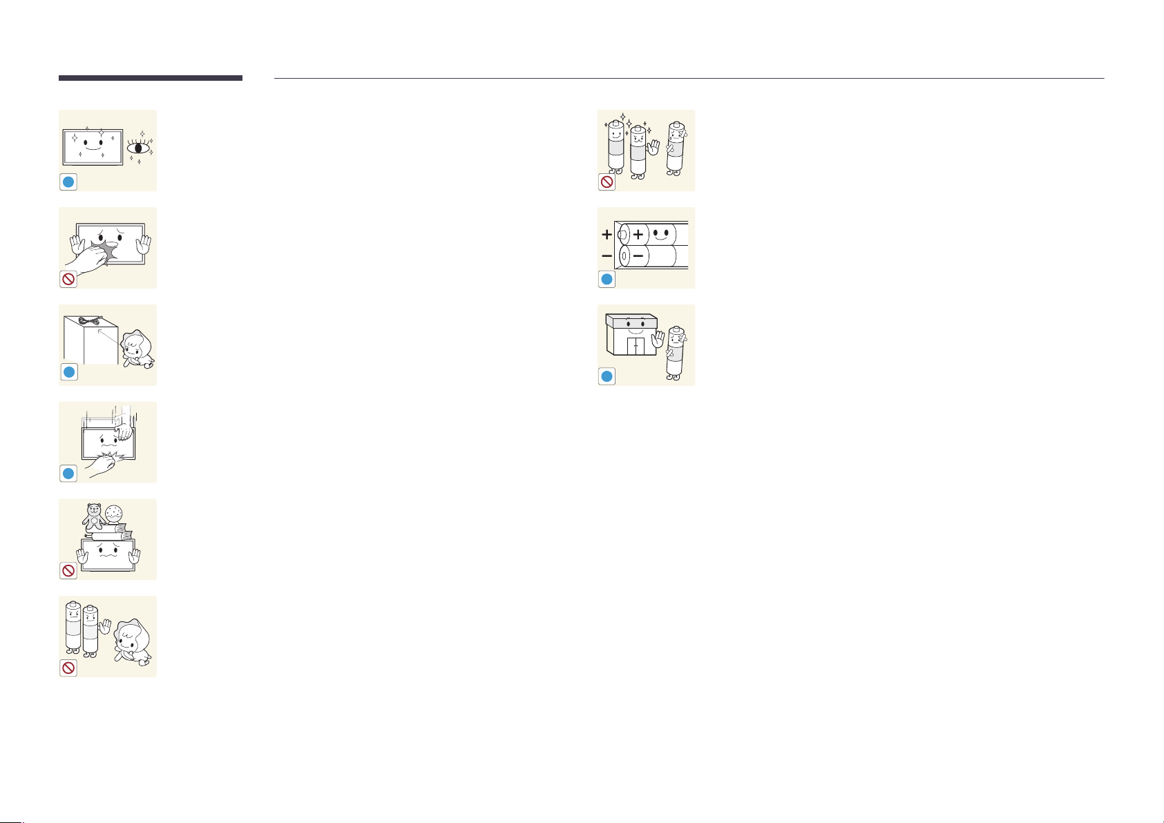
Looking at the screen too close for an extended period of time can
deteriorate your eyesight.
!
Do not use humidifiers or stoves around the product.
•
A fire or electric shock may result.
12
Page 13
Rest your eyes for more than 5 minutes for every 1 hour of product use.
•
Eye fatigue will be relieved.
!
When replacing the battery, insert it with the right polarity (+, -).
•
Otherwise, the battery may become damaged or it may cause fire,
personal injury or damage due to leakage of the internal liquid.
Do not touch the screen when the product has been turned on for an
extended period of time as it will become hot.
!
Store small accessories out of the reach of children.
!
Exercise caution when adjusting the product angle or stand height.
•
Your hand or finger may get stuck and injured.
•
Tilting the product at an excessive angle may cause the product to fall
!
and an injury may result.
Do not place heavy objects on the product.
•
Product failure or personal injury may result.
Be careful that children do not place the battery in their mouths when
removed from the remote control. Place the battery in a location that
children or infants cannot reach.
•
If children have had the battery in their mouths, consult your doctor
immediately.
!
Use only the specified standardized batteries, and do not use a new battery
and a used battery at the same time.
•
Otherwise, the batteries may be damaged or cause fire, personal injury
or damage due to a leakage of the internal liquid.
The batteries (and rechargeable batteries) are not ordinary refuse and must
be returned for recycling purposes. The customer is responsible for returning
the used or rechargeable batteries for recycling.
•
The customer can return used or rechargeable batteries to a nearby
public recycling center or to a store selling the same type of the
battery or rechargeable battery.
13
Page 14

Chapter 02
UP
UP
Preparations
Checking the Contents
Removing the Packaging
―
The following images are for reference only. Real-life situations may differ from what is shown in the
images.
Remove the protective packaging from the box.
1
Cut the strap and open the box.
2
Separate the box from the product. Remove the protective packaging from the product.
3
―
The appearance of actual components may differ from the image shown.
Store the box in a dry area so that it can be used when moving the product in the future.
4
14
Page 15
-
Contact the vendor where you
purchased the product if any
components are missing.
-
The appearance of the components and
items sold separately may differ from the
image shown.
-
A stand is not provided with the product.
To install a stand, you can purchase one
separately.
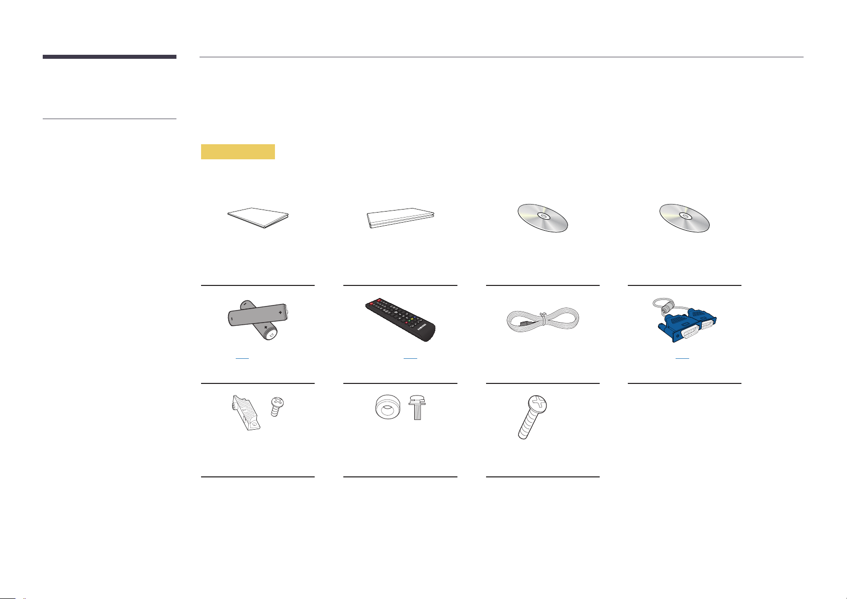
Checking the Components
Components
―
Components may differ in different locations.
Quick setup guide Warranty card
(Not available in some
locations)
User manual MagicInfo Software CD
-
-
+
+
Batteries (P. 21)
(Not available in some locations)
Holder Guide (4EA) (For Video
Wall) / Screw (8EA)
Remote Control (P. 20)
Power cord D-SUB cable (P. 42)
(AA59-00714A)
Holder-Ring (4EA) / Screw (4EA) Screw (1EA) (For function
knob)
15
Page 16
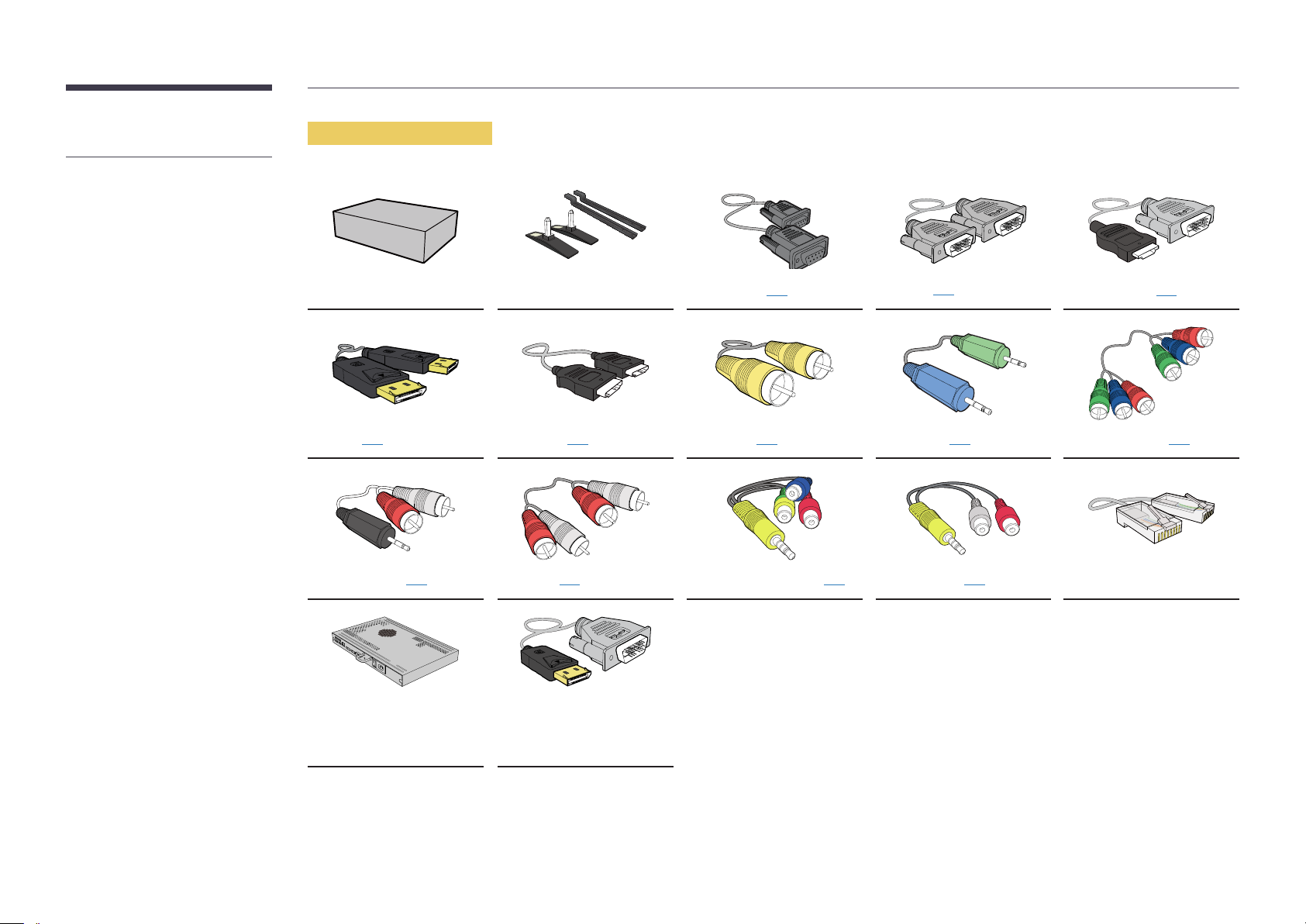
-
The following items can be purchased
at your nearest retailer.
Items sold separately
Wall-mount Kit Stand RS232C cable (P. 54)
DP cable (P. 43) HDMI cable (P.43) Video cable (P.46) Stereo cable (P.23) Component cable (P.46)
RCA stereo cable (P. 48) RCA cable (P. 47) AV/Component adapter (P.47) AUDIO adapter (P. 47) LAN cable
DP-DVI cable
Network Box
(Used to connect a network
box)
DVI cable (P. 42)
HDMI-DVI cable (P. 43)
16
Page 17
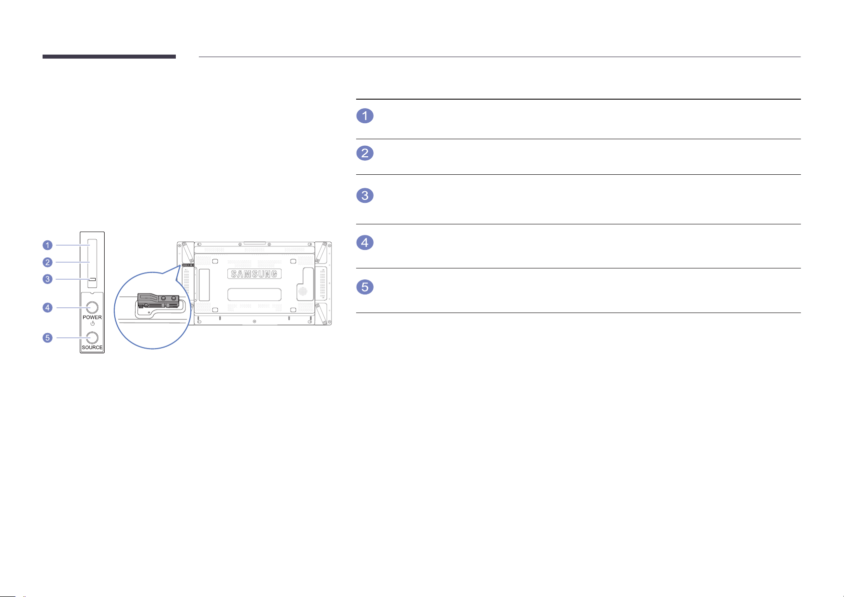
Parts
Buttons Description
Remote Control
Sensor
Aim the remote control towards this spot on the LCD Display.
―
Keep the area between the remote sensor and remote control obstacle-free.
External sensor KIT
―
The External sensor KIT has a remote-control sensor, a brightness sensor and
function keys. If mounting the display onto a wall, you can move the External
sensor KIT to the side of the display.
―
The color and shape of parts may differ from what is shown. Specifications are
subject to change without notice to improve quality.
Light sensor
Power indicator
POWER button
SOURCE button
Automatically detects the intensity of ambient light around a selected display and
adjusts the screen brightness.
Turns off in power-on mode and blinks green in power-saving mode.
Use this button for turning the LCD Display on and off.
Switches from PC mode to Video mode.
Selects the input source that an external device is connected to.
17
Page 18
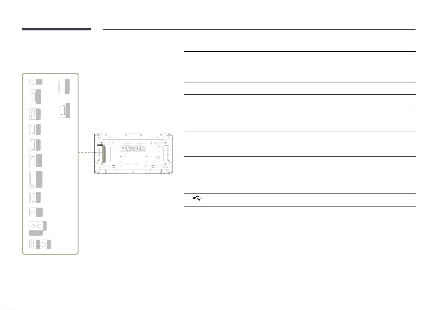
Reverse Side
IR
OUT
CONTROL IN
DP IN HDMI IN 1
HDMI IN 2
DVI IN
(MAGICINFO)
AV /
COMP
AUDIO
OUT
IN
RJ 45
RS232C OUT
RS232C OUTRS232C OUTRS232C OUTRS232C OUTRS232C IN
HDMI IN 2RGB IN
USB
DP OUT
(LOOPOUT)
Port Description
―
The color and shape of parts may differ from what is shown. Specifications are
subject to change without notice to improve quality.
IR OUT
CONTROL IN
DP IN
HDMI IN 1, HDMI IN 2
DP OUT (LOOPOUT)
DVI IN (MAGICINFO)
RGB IN
AV IN / COMP IN
AUDIO OUT
AUDIO IN
RJ45
USB
Receives the remote control signal via the external sensor board and outputs the
signal via LOOP OUT.
Supplies power to the external sensor board or receives the light sensor signal.
Connects to a PC using a DP cable.
Connects to a source device using an HDMI cable.
Connects to another product using a DP cable.
Connects to a source device using a DVI cable or DP-DVI cable.
Connects to a source device using a D-SUB cable.
Connects to a source device using the AV/Component adapter.
Connects to the audio of a source device.
Receives sound from a PC via an audio cable.
Connects to MDC using a LAN cable.
Connect to a USB memory device.
RS232C OUT
RS232C IN
Connects to MDC using an RS232C cable.
18
Page 19
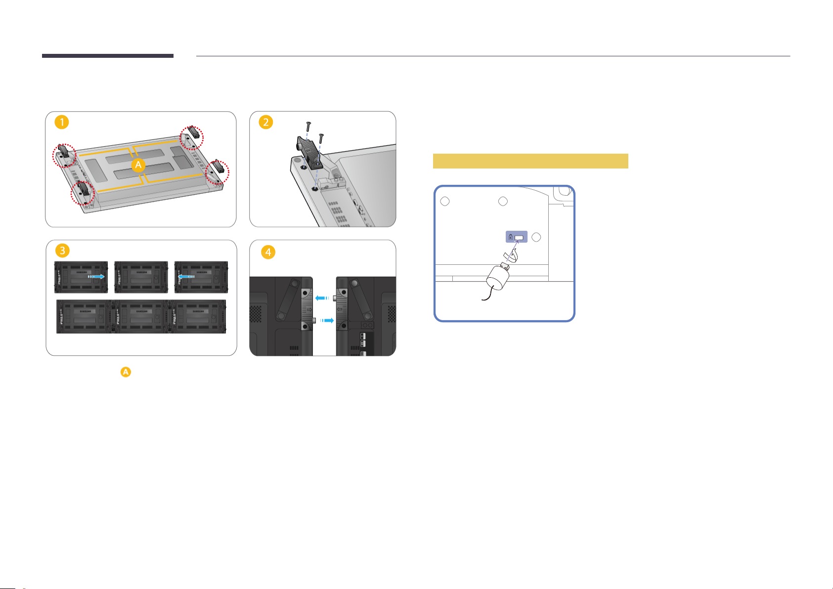
Attaching the holders
―
Fix the holders into on the back of the product using the screws.
―
When displays are connected to form a video wall, the holders will make the gap between displays
uniform on all four sides.
Anti-theft Lock
―
An anti-theft lock allows you to use the product securely even in public places.
―
The locking device shape and locking method depend on the manufacturer. Refer to the user guide
provided with your anti-theft locking device for details.
To lock an anti-theft locking device:
Fix the cable of your anti-theft locking device to a heavy object such as a desk.
1
Put one end of the cable through the loop on the other end.
2
Insert the locking device into the anti-theft lock slot at the back of the product.
3
Lock the locking device.
4
-
An anti-theft locking device can be purchased separately.
-
Refer to the user guide provided with your anti-theft locking device for details.
-
Anti-theft locking devices can be purchased at electronics retailers or online.
19
Page 20
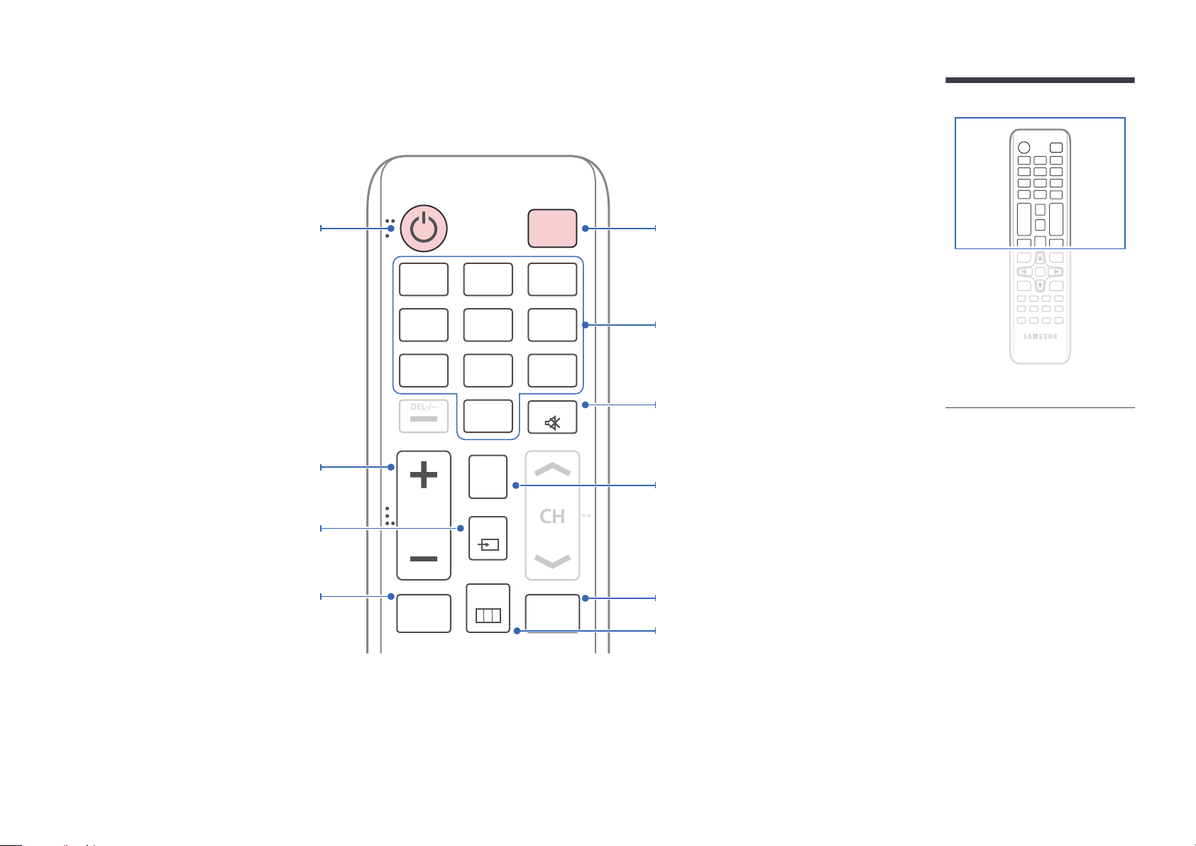
Remote Control
CH
DEL-/--
―
Using other display devices in the same space as the remote control of this product can cause the other display devices to be inadvertently controlled.
Power on the product.
Adjust the volume.
Change the input source.
MagicInfo Lite, MagicInfo Premium S,
MagicInfo Videowall S Launch Button.
The buttons can vary according to the
Player Mode settings.
.QZ
1
GHI
4
PRS
7
VOL
MagicInfo
Lite/S
ABC
2
JKL
5
TUV
8
SYMBOL
0
CONTENT
(HOME)
SOURCE
MENU
OFF
DEF
3
MNO
6
WXY
9
MUTE
BLANK
Power off the product.
Number buttons
Enter the password in the OSD menu.
Mute the sound.
Unmuting the sound: Press MUTE again or press
the volume control(+ VOL -) button.
Contents Home Launch Button.
Temporarily turn off the video and mute the
audio.
Disabling the BLANK function
- Press BLANK one more time.
- Press SOURCE.
- Turn the product off and then on again.
Display or hide the onscreen display menu, or
return to the previous menu.
-
Remote control button functions may
differ for different products.
20
Page 21
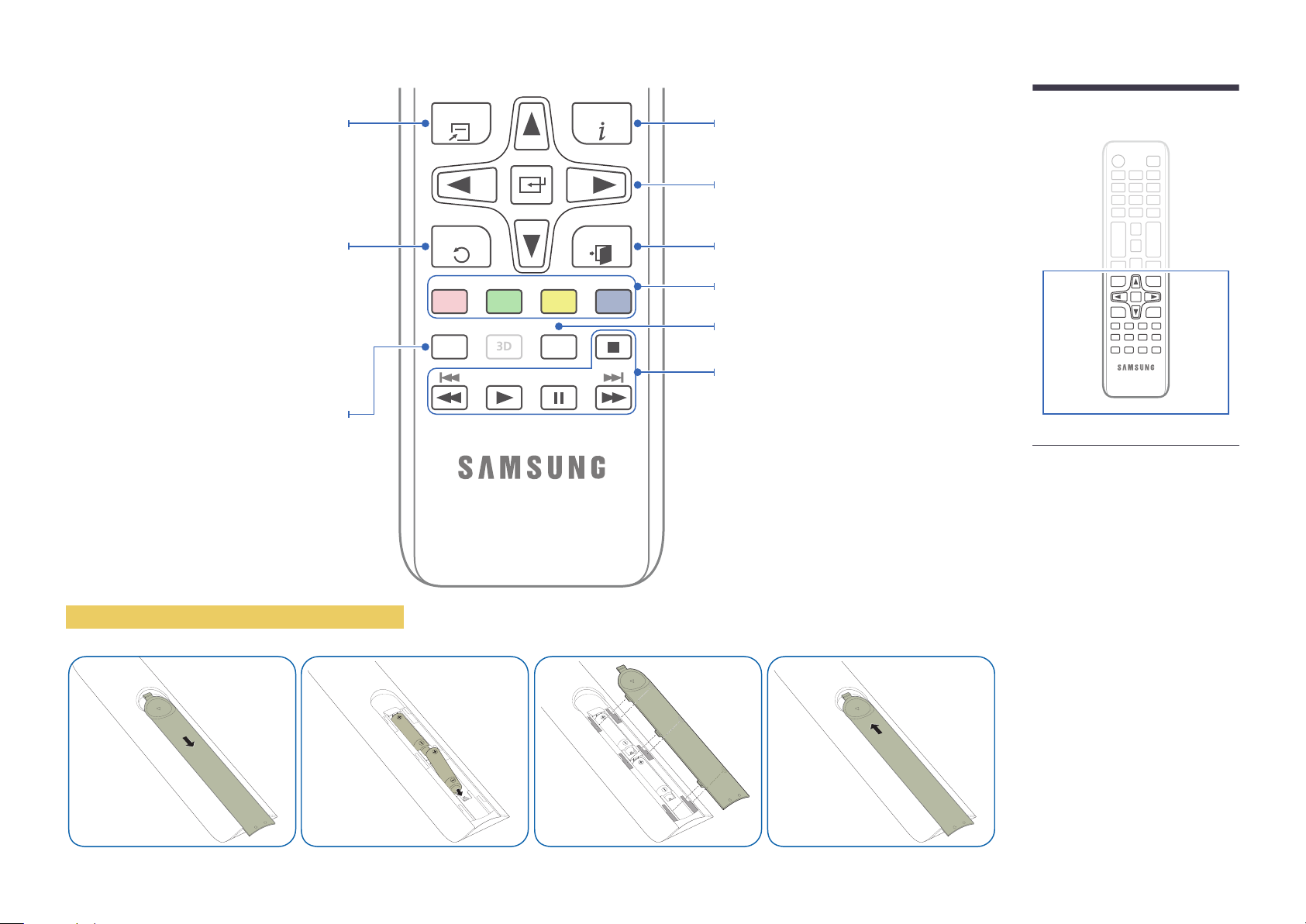
3D
Quickly select frequently used functions.
Return to the previous menu.
TOOLS INFO
EXITRETURN
Display information about the current input
source.
Move to the upper, lower, left or right menu, or
adjust an option's setting.
Confirm a menu selection.
Exit the current menu.
MagicInfo Quick Launch Button.
This button is disabled for products
that do not support MagicInfo.
MagicInfo can only be enabled
when a network box is connected.
To place batteries in the remote control
PC
A
Magicinfo
DVI
B
HDMI
C
LOCK
DP
D
Manually select a connected input source from
PC, DVI, HDMI, or DP.
It sets safe lock function.
Use these buttons in Videos, Photos, Music and
Anynet+ modes.
-
Remote control button functions may
differ for different products.
21
Page 22
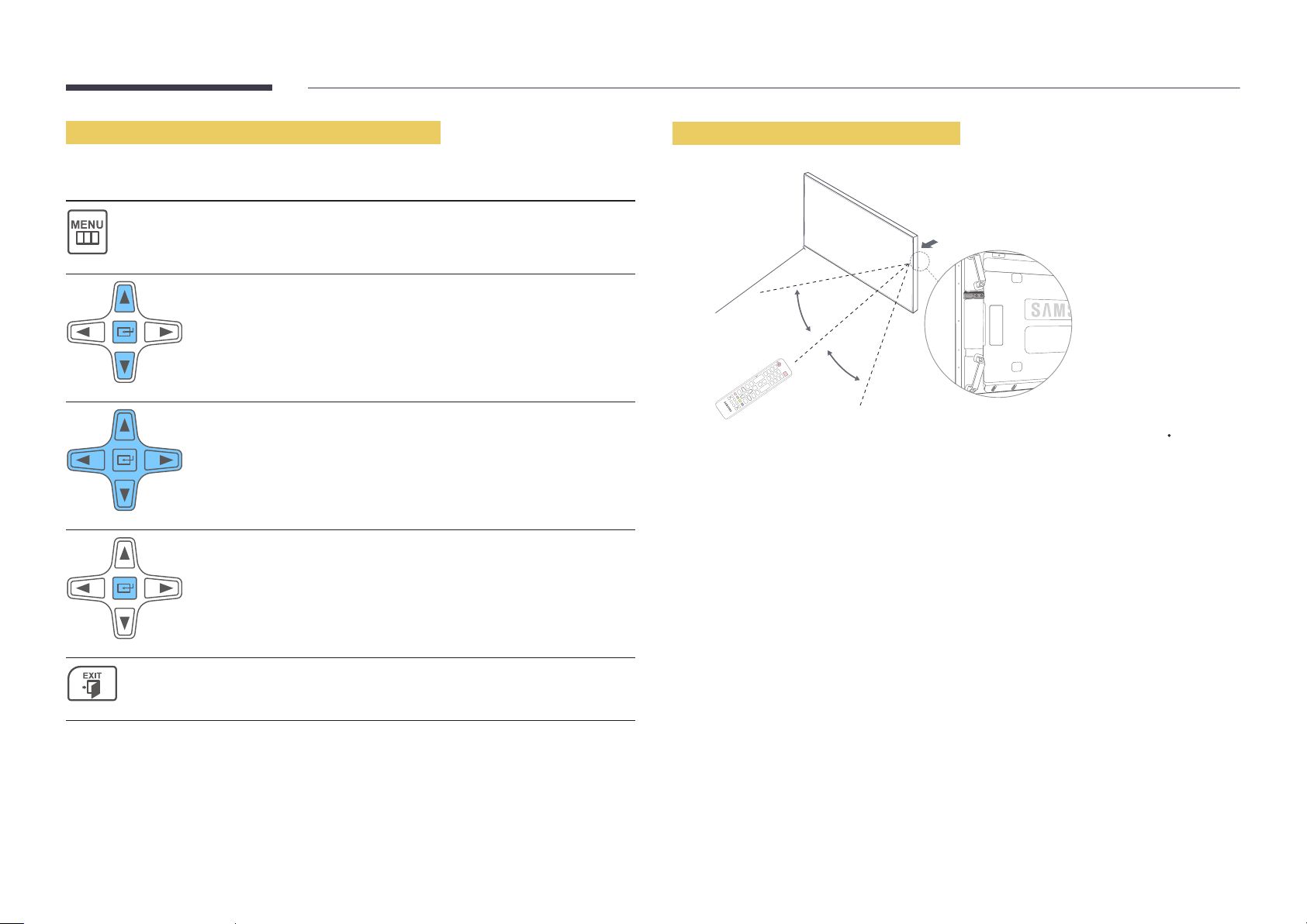
Adjusting the OSD with the Remote Control
Buttons Description
Open the OSD menu.
1
Select from Picture, Network, System or Support in
2
the displayed OSD menu screen.
Change settings as desired.
3
Remote Control Reception Range
7m-10m
30˚
30˚
Use the remote control within 7m to 10m from the sensor on the product at an angle of 30 from the
left and right.
―
Store used batteries out of reach of children and recycle.
―
Do not use a new and used battery together. Replace both batteries at the same time.
―
Remove batteries when the remote control is not to be used for an extended period of time.
Finish setting.
4
Close the onscreen display (OSD) menu.
5
22
Page 23
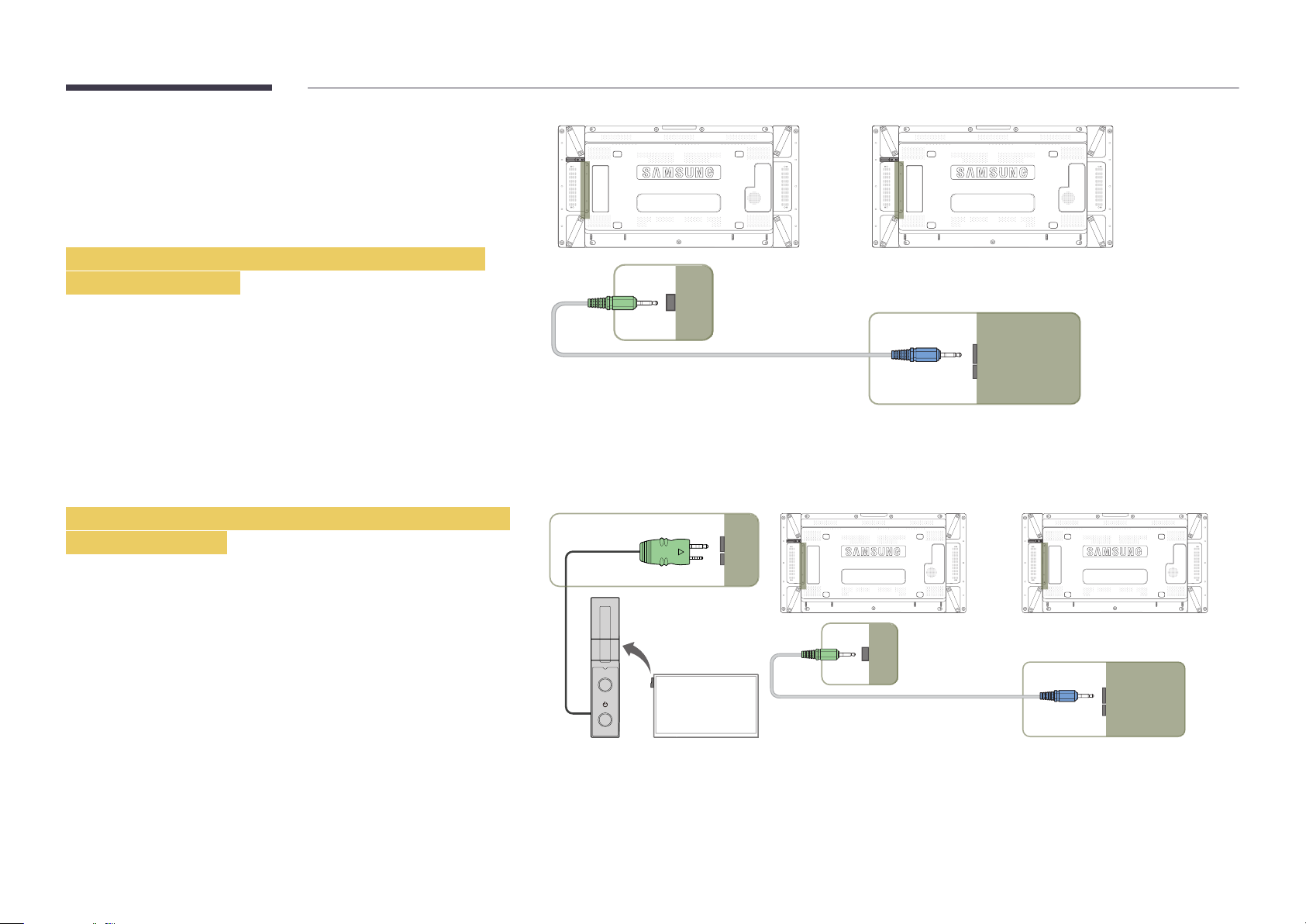
Connection Using an IR Stereo Cable (sold
1 2
CONTROL IN
IR OUT
1 2
IR OUT CONTROL IN
CONTROL IN
POWER
SOURCE
separately)
―
Turn off the device before connecting the External Sensor Kit. After it is
connected, turn on the device.
Controlling more than one display product using
your remote control
•
Connect the IR OUT port on the product to the IR / AMBIENT SENSOR IN
port on the other display product using the dedicated stereo cable.
•
A command sent from the remote control pointed at product
received by both display products
―
The appearance may differ depending on the product.
1
and 2.
Controlling more than one display product using an
external sensor kit
•
A command sent from the remote control pointed at product
which the external sensor kit is connected) will be received by both display
products
―
The appearance may differ depending on the product.
1
and 2.
1
1
will be
(to
23
Page 24
Before Installing the Product (Installation Guide)
To prevent injury, this apparatus must be securely attached to the floor/wall in accordance with the installation instructions.
•
Ensure that an authorized installation company installs the wall mount.
•
Otherwise, it may fall and cause personal injury.
•
Make sure to install the specified wall mount.
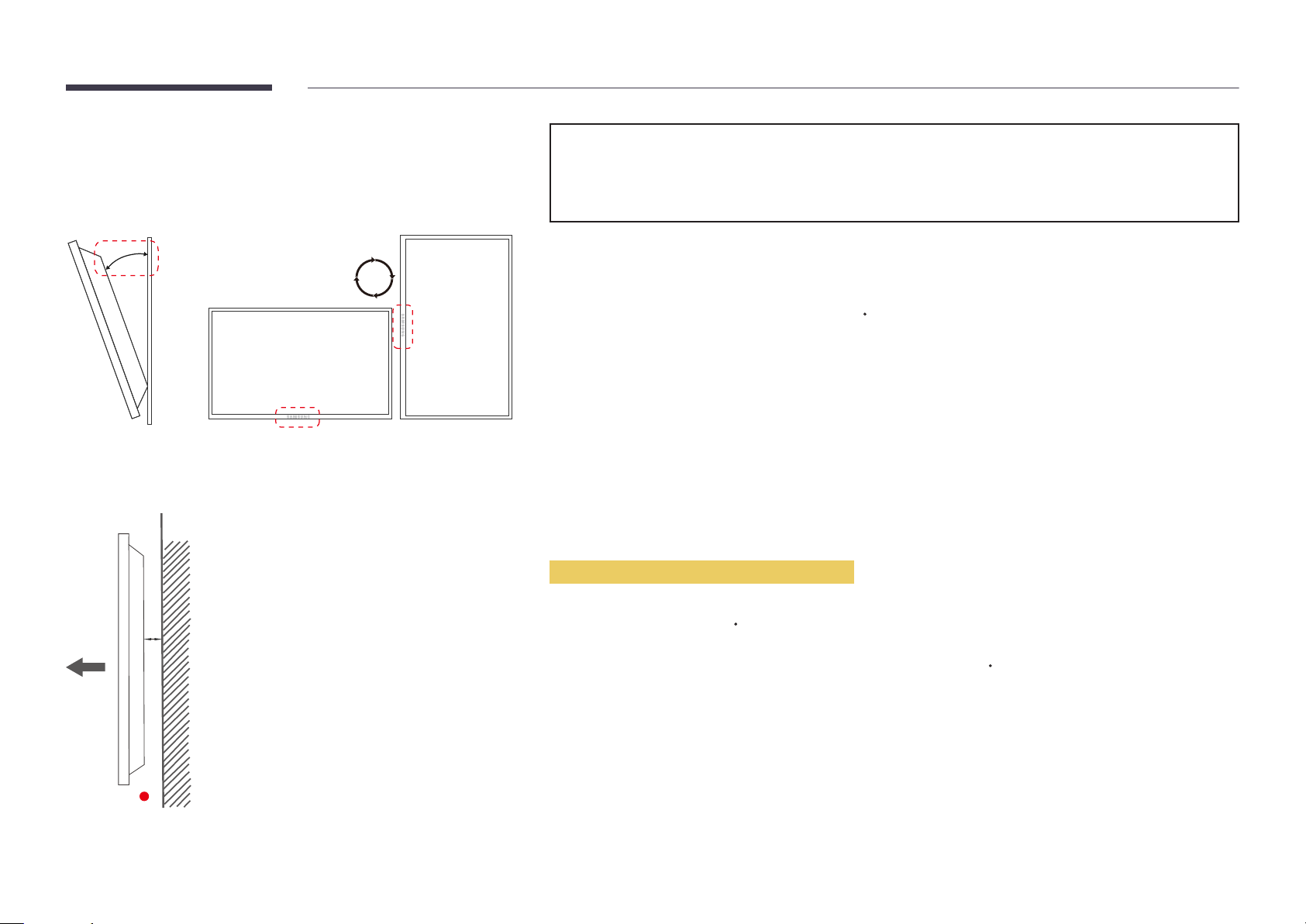
15˚
Tilting Angle and Rotation
―
Contact Samsung Customer Service Center for further details.
•
The product can be tilted at a maximum angle of 15
•
To use the product vertically (portrait), turn it clockwise so that the LED is pointing down.
from a perpendicular wall surface.
Ventilation
Installation on a Perpendicular Wall
A Minimum 40 mm
B Ambient temperature: Under 35
A
•
When installing the product on a perpendicular wall, allow at least 40 mm of space between the product and wall surface
for ventilation and ensure that the ambient A temperature is kept below 35
C
C.
B
Figure 1.1 Side view
24
Page 25
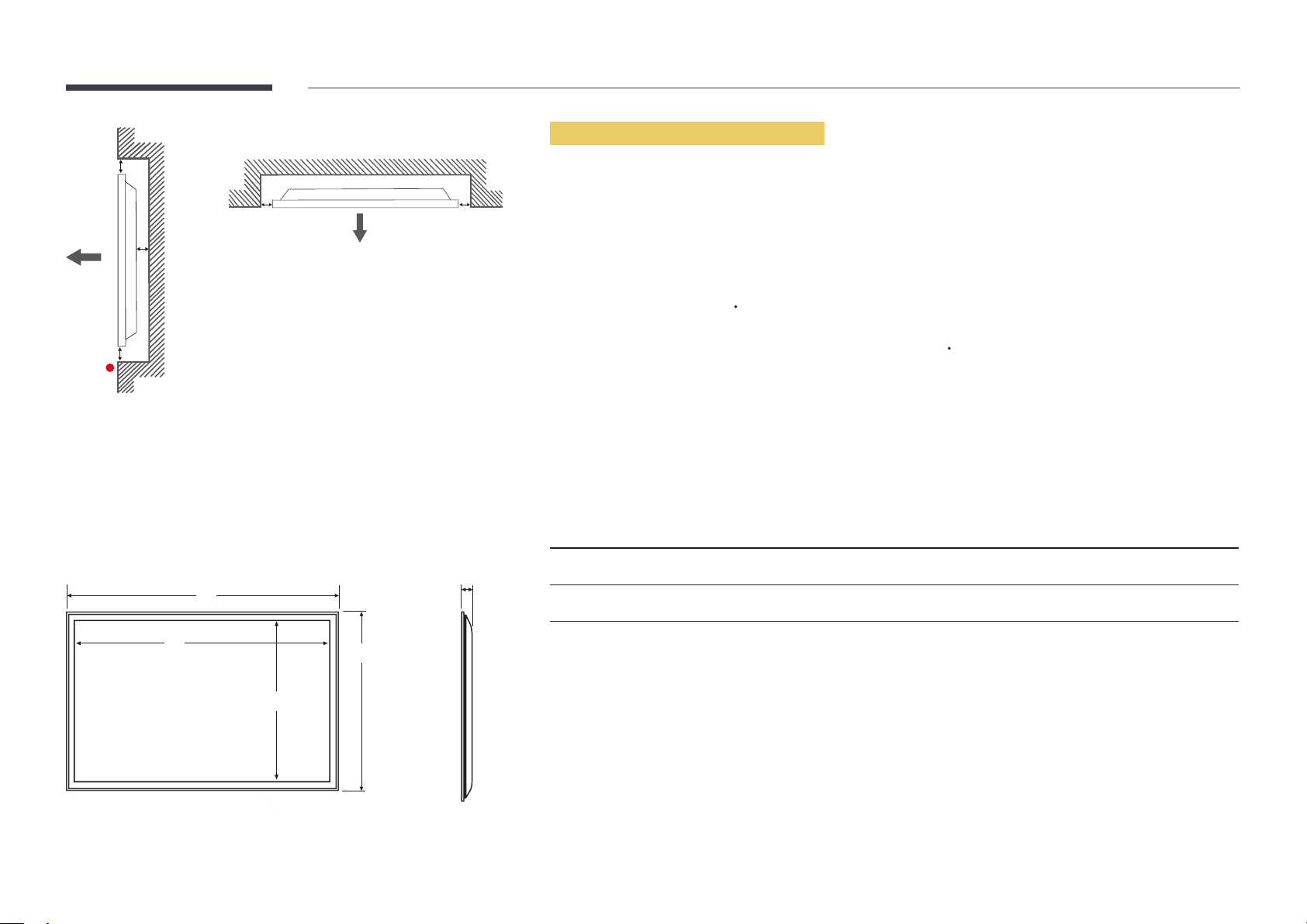
Figure 1.3 Top view
B
Installation on an Indented Wall
―
Contact Samsung Customer Service Center for further details.
A
C
E
Figure 1.2 Side view
Dimensions
1
2
D D
4
5
Plane view
A Minimum 40 mm
B Minimum 70 mm
C Minimum 50 mm
D Minimum 50 mm
E Ambient temperature: Under 35
―
When installing the product on an indented wall, allow at least the space specified above between the product and wall for
ventilation and ensure that the ambient temperature is kept below 35
Model name
UD46C 1023.8 1018.3 572.9 578.4 96.0
UD55C 1215.3 1209.8 680.6 686.1 96.0
―
All drawings are not necessarily to scale. Some dimensions are subject to change without prior notice.
Refer to the dimensions prior to performing installation of your product. Not responsible for typographical or printed errors.
1
C
C.
Unit: mm
2
3 4
5
3
25
Page 26

Installing the Wall Mount
1
Preparing before installing Wall-Mount
To install a wall-mount from another manufacturer, use the Holder-Ring.
Installing the Wall Mount Kit
The wall mount kit (sold separately) allows you to mount the product on the wall.
For detailed information on installing the wall mount, see the instructions provided with the wall mount.
We recommend you contact a technician for assistance when installing the wall mount bracket.
Samsung Electronics is not responsible for any damage to the product or injury to yourself or others if you elect to install the
wall mount on your own.
26
Page 27
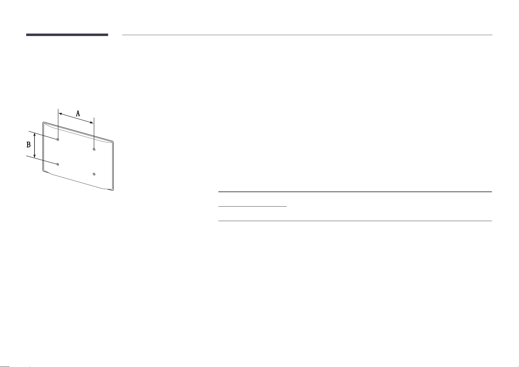
Wall Mount Kit Specications (VESA)
―
Install your wall mount on a solid wall perpendicular to the floor. Before
attaching the wall mount to surfaces other than plaster board, please contact
your nearest dealer for additional information.
If you install the product on a slanted wall, it may fall and result in severe
personal injury.
•
Samsung wall mount kits contain a detailed installation manual and all parts necessary for assembly are provided.
•
Do not use screws that are longer than the standard length or do not comply with the VESA standard screw
specifications. Screws that are too long may cause damage to the inside of the product.
•
For wall mounts that do not comply with the VESA standard screw specifications, the length of the screws may differ
depending on the wall mount specifications.
•
Do not fasten the screws too firmly. This may damage the product or cause the product to fall, leading to personal injury.
Samsung is not liable for these kinds of accidents.
•
Samsung is not liable for product damage or personal injury when a non-VESA or non-specified wall mount is used or the
consumer fails to follow the product installation instructions.
•
Do not mount the product at more than a 15 degree tilt.
•
Always have two people mount the product on a wall.
•
Standard dimensions for wall mount kits are shown in the table below.
Unit: mm
Model name VESA screw hole
Standard Screw Quantity
specs (A * B) in
millimeters
UD46C
600 × 400 M8 4
UD55C
―
Do not install your Wall Mount Kit while your product is turned on. It may result in personal injury due to electric shock.
27
Page 28
Remote Control (RS232C)
Cable Connection
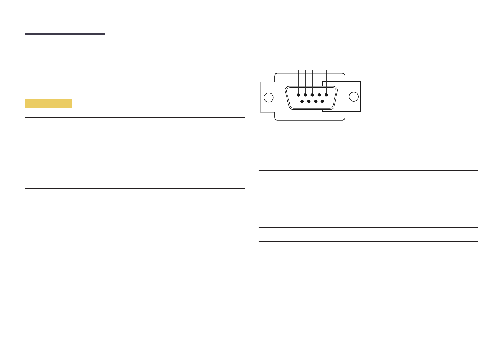
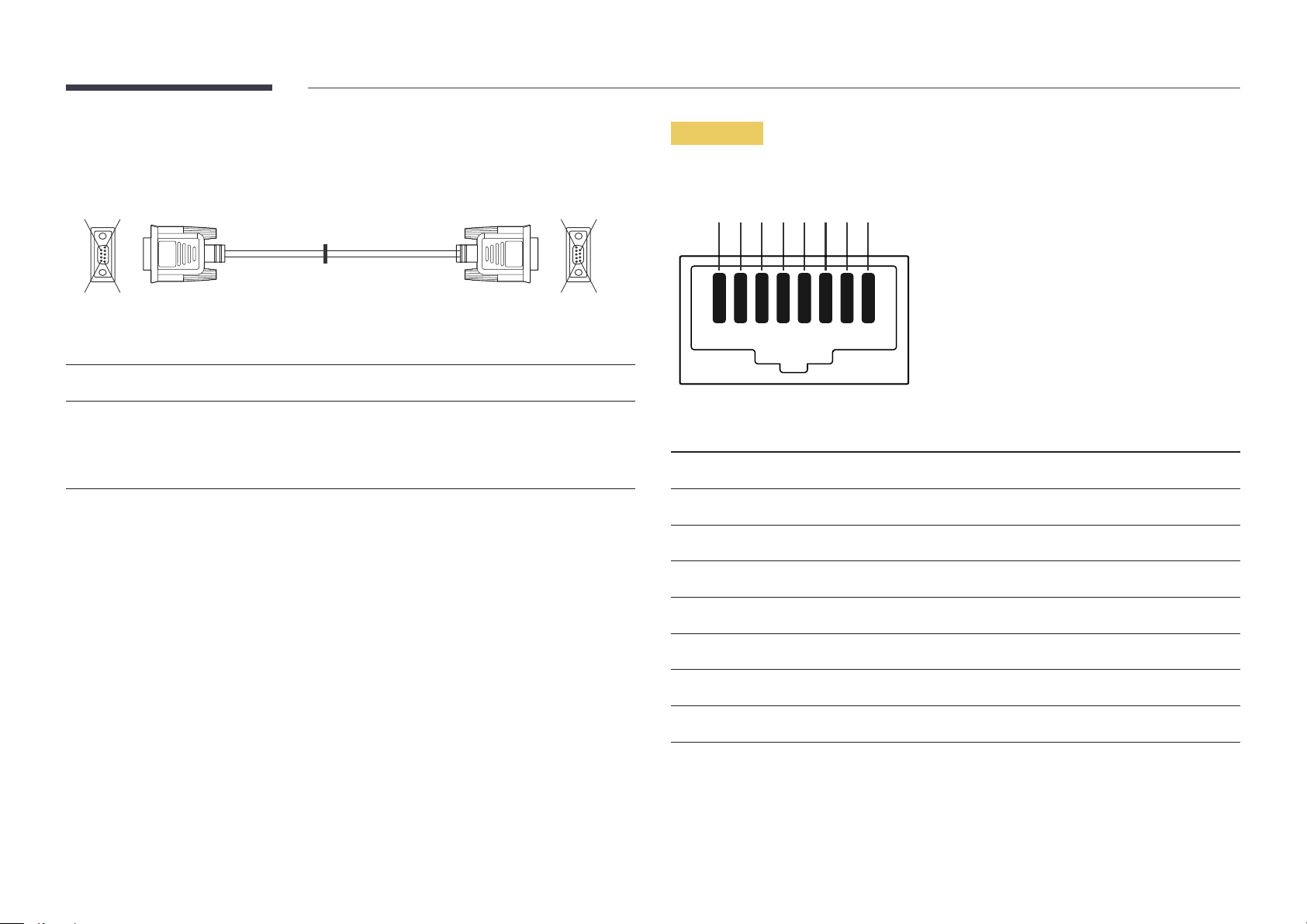
RS232C Cable
•
Pin assignment
1 2 3 4 5
Interface
Pin
Bit rate
Data bits
Parity
Stop bit
Flow control
Maximum length
RS232C (9 pins)
TxD (No.2), RxD (No.3), GND (No.5)
9600 bps
8 bit
None
1 bit
None
15 m (only shielded type)
6 7 8 9
Pin Signal
1
2
3
4
5
6
7
8
9
Detect data carrier
Received data
Transmitted data
Prepare data terminal
Signal ground
Prepare data set
Send request
Clear to send
Ring indicator
28
Page 29
•
RS232C cable
Connector: 9-Pin D-Sub
Cable: Cross cable
LAN Cable
•
Pin assignment
5
1
6
-P1- -P2-
-P1- -P1- -P2- -P2-
Female Rx
Tx
Gnd
2
3
5
-------->
<--------
----------
3
2
5
Tx
Rx
Gnd
Female
59
9
1
6
1 2 3 4 5 6 7 8
Pin No Standard Color Signal
1 White and orange TX+
2 Orange TX-
3 White and green RX+
4 Blue NC
5 White and blue NC
6 Green RX-
7 White and brown NC
8 Brown NC
29
Page 30
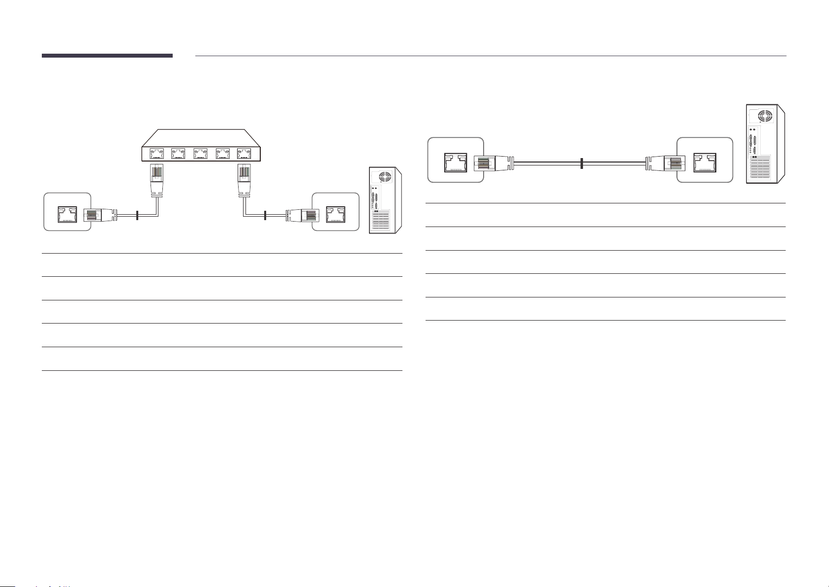
•
Connector : RJ45
Direct LAN cable (PC to HUB)
Cross LAN cable (PC to PC)
HUB
P1P2
RJ45 MDC RJ45 MDC
Signal
TX+
TX-
RX+
RX-
P1
P1 P2 Signal
1 <--------> 1 TX+
2 <--------> 2 TX-
3 <--------> 3 RX+
6 <--------> 6 RX-
P2
RJ45 MDC
Signal
TX+
TX-
RX+
RX-
P1 P2
P1 P2 Signal
1 <--------> 3 RX+
2 <--------> 6 RX-
3 <--------> 1 TX+
6 <--------> 2 TX-
30
Page 31

Connection
•
Connection 1
•
Connection 2
RJ45 MDC RJ45 MDC
RS232C
IN OUT
RS232C
IN OUT
RS232C
IN OUT
RS232C
IN OUT
•
Connection 3
RJ45 RS232C
OUT
RS232C
IN OUT
RS232C
IN OUT
RS232C
IN OUT
31
Page 32

Control Codes
No. Command type Command Value range
Viewing control state (Get control command)
Header Command ID Data length Checksum
0xAA Command type 0
Controlling (Set control command)
Header Command ID Data length Data Checksum
0xAA Command type 1 Value
Command
No. Command type Command Value range
1
2
3
4
Power control 0x11 0~1
Volume control 0x12 0~100
Input source control 0x14 -
Screen mode control 0x18 -
10
11
•
All communications take place in hexadecimals. The checksum is calculated by adding up all
values except the header. If a checksum adds up to be more than 2 digits as shown below
(11+FF+01+01=112), the first digit is removed.
E.g. Power On & ID=0
Header Command ID Data length Data 1 Checksum
0xAA 0x11 1 "Power"
Header Command ID Data length Data 1 12
0xAA 0x11 1 1
•
To control all devices connected by a serial cable simultaneously irrespective of IDs, set the ID as
"0xFE" and transmit commands. Commands will be executed by each device but ACK will not
respond.
Video Wall On 0x84 0~1
Video Wall User Control 0x89 -
5
6
7
8
9
Screen size control 0x19 0~255
PIP On/Off control 0x3C 0~1
Auto adjustment control 0x3D 0
Video wall mode control 0x5C 0~1
Safety Lock 0x5D 0~1
32
Page 33

Power control
Volume control
•
Function
A product can be powered on and off using a PC.
•
Viewing power state (Get Power ON / OFF Status)
Header Command ID Data length Checksum
0xAA 0x11 0
•
Setting power ON/Off (Set Power ON / OFF)
Header Command ID Data length Data Checksum
0xAA 0x11 1 "Power"
"Power": Power code to be set on a product.
1: Power ON
0: Power OFF
•
Ack
Header Command ID Data length Ack/Nak r-CMD Val1 Checksum
0xAA 0xFF 3 'A' 0x11 "Power"
"Power": Power code to be set on a product.
•
Nak
Header Command ID Data length Ack/Nak r-CMD Val1 Checksum
•
Function
The volume of a product can be adjusted using a PC.
•
Viewing volume state (Get Volume Status)
Header Command ID Data length Checksum
0xAA 0x12 0
•
Setting the volume (Set Volume)
Header Command ID Data length Data Checksum
0xAA 0x12 1 "Volume"
"Volume": Volume value code to be set on a product. (0-100)
•
Ack
Header Command ID Data length Ack/Nak r-CMD Val1 Checksum
0xAA 0xFF 3 'A' 0x12 "Volume"
"Volume": Volume value code to be set on a product. (0-100)
•
Nak
Header Command ID Data length Ack/Nak r-CMD Val1 Checksum
0xAA 0xFF 3 'N' 0x12 "ERR"
0xAA 0xFF 3 'N' 0x11 "ERR"
"ERR" : A code showing what error has occurred.
"ERR" : A code showing what error has occurred.
33
Page 34

Input source control
•
Function
The input source of a product can be changed using a PC.
•
Viewing input source state (Get Input Source Status)
Header Command ID Data length Checksum
0xAA 0x14 0
•
Setting the input source (Set Input Source)
Header Command ID Data length Data Checksum
0xAA 0x14 1 "Input Source"
0x24 HDMI2_PC
0x25 DisplayPort
―
DVI_video, HDMI1_PC and HDMI2_PC cannot be used with the Set command. They only respond to
"Get" commands.
―
MagicInfo is only available with models that contain the MagicInfo function.
―
RF(TV), DTV are only available with models that include a TV.
•
Ack
Header Command ID Data length Ack/Nak r-CMD Val1 Checksum
0xAA 0xFF 3 'A' 0x14 "Input
Source"
"Input Source": An input source code to be set on a product.
0x14 PC
0x18 DVI
0x0C Input source
0x08 Component
0x20 MagicInfo
0x1F DVI_video
0x30 RF( TV)
0x40 DT V
0x21 HDMI1
0x22 HDMI1_PC
0x23 HDMI2
"Input Source": An input source code to be set on a product.
•
Nak
Header Command ID Data length Ack/Nak r-CMD Val1 Checksum
0xAA 0xFF 3 'N' 0x14 "ERR"
"ERR" : A code showing what error has occurred.
34
Page 35

Screen mode control
•
Function
The screen mode of a product can be changed using a PC.
Screen mode cannot be controlled when the Video Wall function is enabled.
―
This control can only be used on models that include a TV.
•
Viewing screen status (Get Screen Mode Status)
Header Command ID Data length Checksum
0xAA 0x18 0
Header Command ID Data length Ack/Nak r-CMD Val1 Checksum
0xAA 0xFF 3 'N' 0x18 "ERR"
"ERR": A code showing what error has occurred
Screen size control
•
Function
The screen size of a product can be changed using a PC.
•
Viewing the screen size (Get Screen Size Status)
•
Setting the picture size (Set Picture Size)
Header Command ID Data
length
0xAA 0x18 1 "Screen Mode"
"Screen Mode": A code that sets the product status
0x01 16 : 9
0x04 Zoom
0x31 Wide Zoom
0x0B 4 : 3
•
Ack
Header Command ID Data length Ack/Nak r-CMD Val1 Checksum
0xAA 0xFF 3 'A' 0x18 "Screen
"Screen Mode": A code that sets the product status
•
Nak
Data Checksum
Mode"
Header Command ID Data length Checksum
0xAA 0x19 0
•
Ack
Header Command ID Data
length
0xAA 0xFF 3 'A' 0x19 "Screen Size"
"Screen Size": product screen size (range: 0 – 255, unit: inch)
•
Nak
Header Command ID Data
length
0xAA 0xFF 3 'N' 0x19 "ERR"
"ERR": A code showing what error has occurred
Ack/Nak r-CMD Val1 Checksum
Ack/Nak r-CMD Val1 Checksum
35
Page 36

PIP On/Off control
Auto adjustment control (PC and BNC only)
•
Function
The PIP mode of a product can be turned on or off using a PC.
―
Only available on models that have the PIP function.
―
The mode cannot be controlled if Video Wall is set to On.
―
This function is not available in MagicInfo.
•
Viewing PIP on/off state (Get the PIP ON / OFF Status)
Header Command ID Data length Checksum
0xAA 0x3C 0
•
Setting PIP on/off (Set the PIP ON / OFF)
Header Command ID Data length Data Checksum
0xAA 0x3C 1 "PIP"
"PIP": A code used to turn the PIP mode of a product on or off
1: PIP ON
0: PIP OFF
•
Ack
Header Command ID Data
length
0xAA 0xFF 3 'A' 0x3C "PIP"
Ack/Nak r-CMD Val1 Checksum
•
Function
Automatically adjust the PC system screen using a PC.
•
Viewing auto adjustment state (Get Auto Adjustment Status)
None
•
Setting auto adjustment (Set Auto Adjustment)
Header Command ID Data length Data Checksum
0xAA 0x3D 1 "Auto
Adjustment"
"Auto Adjustment" : 0x00 (at all times)
•
Ack
Header Command ID Data
length
0xAA 0xFF 3 'A' 0x3D "Auto
•
Nak
Header Command ID Data
length
0xAA 0xFF 3 'A' 0x3D "ERR"
Ack/Nak r-CMD Val1 Checksum
Adjustment"
Ack/Nak r-CMD Val1 Checksum
"PIP": A code used to turn the PIP mode of a product on or off
•
Nak
Header Command ID Data
length
0xAA 0xFF 3 'A' 0x3C "PIP"
"ERR": A code showing what error has occurred
Ack/Nak r-CMD Val1 Checksum
"ERR": A code showing what error has occurred
36
Page 37

Video Wall Mode Control
Safety Lock
•
Function
Video Wall mode can be activated on a product using a PC.
This control is only available on a product whose Video Wall is enabled.
•
Viewing video wall mode (Get Video Wall Mode)
Header Command ID Data length Checksum
0xAA 0x5C 0
•
Setting the video wall (Set Video Wall Mode)
Header Command ID Data length Data Checksum
0xAA 0x5C 1 "Video Wall Mode"
"Video Wall Mode": A code used to activate Video Wall mode on a product
1: Full
0: Natural
•
Ack
Header Command ID Data
length
0xAA 0xFF 3 'A' 0x5C "Video Wall
Ack/Nak r-CMD Val1 Checksum
Mode"
•
Function
PC can be used to turn the Safety Lock function on or off on a product.
This control is available regardless of whether or not the power is turned on.
•
Viewing the safety lock state (Get Safety Lock Status)
Header Command ID Data length Checksum
0xAA 0x5D 0
•
Enabling or disabling safety lock (Set Safety Lock Enable / Disable)
Header Command ID Data length Data Checksum
0xAA 0x5D 1 "Safety Lock"
"Safety Lock": Safety lock code to be set on a product
1: ON
0: OFF
•
Ack
Header Command ID Data
length
0xAA 0xFF 3 'A' 0x5D "Safety Lock"
Ack/Nak r-CMD Val1 Checksum
"Video Wall Mode": A code used to activate Video Wall mode on a product
•
Nak
Header Command ID Data
length
0xAA 0xFF 3 'A' 0x5C "ERR"
"ERR": A code showing what error has occurred
Ack/Nak r-CMD Val1 Checksum
"Safety Lock": Safety lock code to be set on a product
•
Nak
Header Command ID Data
length
0xAA 0xFF 3 'N' 0x5D "ERR"
"ERR": A code showing what error has occurred
Ack/Nak r-CMD Val1 Checksum
37
Page 38

Video Wall On
Video Wall User Control
•
Function
Turn Video Wall on or off on the product from your computer.
•
Get Video Wall On/Off Status
Header Command ID Data length Checksum
0xAA 0x84 0
•
Set Video Wall On/Off
Header Command ID Data length Data Checksum
0xAA 0x84 1 V.Wall_On
•
V.Wall_On : Video Wall code to be assigned to the product
1: Video Wall ON
0: Video Wall OFF
•
Ack
Header Command ID Data length Ack/Nak r-CMD Val1 Checksum
0xAA 0xFF 3 'A' 0x84 V.Wall_
On
V.Wall_On : Same as above
•
Nak
•
Function
Turn the Video Wall function on or off on the product from your computer.
•
Get Video Wall Status
Header Command ID Data length Checksum
0xAA 0x89 0
•
Set Video Wall
Header Command ID Data length Val1 Val2 Checksum
0xAA 0x89 2 Wall_Div Wall_SNo
Wall_Div: Video Wall Divider code assigned to the product
Header Command ID Data length Ack/Nak r-CMD Val1 Checksum
0xAA 0xFF 3 'N' 0x84 ERR
"ERR": A code showing what error has occurred
38
Page 39

5x5 Video Wall Model
10x10 Video Wall Model
O
1
2
3
4
5
1 2 3 4
0x00 0x00 0x00 0x00
0x11 0x12 0x13 0x14
0x21 0x22 0x23 0x24
0x31 0x32 0x33 0x34
0x41 0x42 0x43 0x44
0x51 0x52 0x53 0x54
5
0x00
0x15
0x25
0x35
0x45
0x55
O
1
2
3
4
5
6
7
8
9
10
11
1 2 3 4 5 6 7 8 9 10 11 12 13 14
0x00 0x00 0x00 0x00 0x00 0x00 0x00 0x00 0x00 0x00 0x00 0x00 0x00 0x00
0x11 0x12 0x13 0x14 0x15 0x16 0x17 0x18 0x19 0x1A 0x1B 0x1C 0x1D 0x1E
0x21 0x22 0x23 0x24 0x25 0x26 0x27 0x28 0x29 0x2A 0x2B 0x2C 0x2D 0x2E
0x31 0x32 0x33 0x34 0x35 0x36 0x37 0x38 0x39 0x3A 0x3B 0x3C 0x3D 0x3E
0x41 0x42 0x43 0x44 0x45 0x46 0x47 0x48 0x49 0x4A 0x4B 0x4C 0x4D 0x4E
0x51 0x52 0x53 0x54 0x55 0x56 0x57 0x58 0x59 0x5A 0x5B 0x5C 0x5D 0x5E
0x61 0x62 0x63 0x64 0x65 0x66 0x67 0x68 0x69 0x6A 0x6B 0x6C 0x6D 0x6E
0x71 0x72 0x73 0x74 0x75 0x76 0x77 0x78 0x79 0x7A 0x7B 0x7C 0x7D 0x7E
0x81 0x82 0x83 0x84 0x85 0x86 0x87 0x88 0x89 0x8A 0x8B 0x8C N/A N/A
0x91 0x92 0x93 0x94 0x95 0x96 0x97 0x98 0x99 0x9A 0x9B N/A N/A N/A
0xA1 0xA2 0xA3 0xA4 0xA5 0xA6 0xA7 0xA8 0xA9 0xAA N/A N/A N/A N/A
0xB1 0xB2 0xB3 0xB4 0xB5 0xB6 0xB7 0xB8 0xB9 N/A N/A N/A N/A N/A
15
0x00
0x1F
0x2F
0x3F
0x4F
0x5F
0x6F
N/A
N/A
N/A
N/A
N/A
12
13
14
15
Wall_SNo : Product Number code assigned to the product
0xC1 0xC2 0xC3 0xC4 0xC5 0xC6 0xC7 0xC8 N/A N/A N/A N/A N/A N/A
0xD1 0xD2 0xD3 0xD4 0xD5 0xD6 0xD7 N/A N/A N/A N/A N/A N/A N/A
0xE1 0xE2 0xE3 0xE4 0xE5 0xE6 0xE7 N/A N/A N/A N/A N/A N/A N/A
0xF1 0xF2 0xF3 0xF4 0xF5 0xF6 N/A N/A N/A N/A N/A N/A N/A N/A
N/A
N/A
N/A
N/A
39
Page 40

5x5 Video Wall Model : ( 1 ~ 25 )
•
Ack
Set Number
1
2
...
24
25
Data
0x01
0x02
...
0x18
0x19
10x10 Video Wall Model : ( 1 ~ 100)
Set Number
1 0x01
2 0x02
... ...
99 0x63
100 0x64
Data
Header Command ID Data length Ack/Nak r-CMD Val1 Val2 Checksum
0xAA 0xFF 4 'A' 0x89 Wall_Div Wall_SNo
•
Nak
Header Command ID Data length Ack/Nak r-CMD Val1 Checksum
0xAA 0xFF 3 'N' 0x89 ERR
"ERR": A code showing what error has occurred
40
Page 41

Chapter 03
Connecting and Using a Source Device
Before Connecting
Check the following before you connect this product with other devices. Devices that can be connected to this product
include PCs, camcorders, speakers, set top boxes and DVD/Blu-ray Disc players.
Pre-connection Checkpoints
―
Before connecting a source device, read the user manual provided with it.
The number and locations of ports on source devices may differ from device to
device.
―
Do not connect the power cable until all connections are completed.
Connecting the power cable during connection may damage the product.
―
Connect the sound ports correctly: left = white and right = red.
―
Check the types of ports at the back of the product you want to connect.
41
Page 42

Connecting to a PC
RGB IN
AUDIO IN
RGB OUT
AUDIO OUT
DVI IN
AUDIO IN
DVI OUT
AUDIO OUT
•
Do not connect the power cable before connecting all other cables.
Ensure you connect a source device first before connecting the power cable.
•
A PC can be connected to the product in a variety of ways.
Select a connection method suitable for your PC.
―
Connecting parts may differ in different products.
Connection using the D-SUB cable (Analog type)
Connection using a DVI cable (Digital type)
42
Page 43

Connection Using an HDMI-DVI Cable
HDMI IN 1, HDMI IN 2
AUDIO IN
DVI OUT
AUDIO OUT
HDMI IN 1, HDMI IN 2
HDMI OUT
DP IN
DP OUT
―
When you connect a PC to the product using an HDMI-DVI cable, set Edit Name to DVI PC to
access video and audio content stored on the PC.
Connection Using an HDMI Cable
Connection Using an DP Cable
•
Precautions for using DP
―
To increase the standby power capacity, the product stops DP communication when it is
turned off or in power-saving mode.
If the product in dual monitor mode is turned off or goes into power-saving mode, monitor
setting changes may not be updated. As a result, screen output may not be displayed properly.
In the occurrence of this issue, set Max. Power Saving to Off before using the product.
―
Some graphics cards that are not compliant with the DP standard may prevent the Windows
Booting/Bios screen from being displayed when the product is in power-saving mode. If this is
the case, make sure to turn on the product first before turning on your PC.
43
Page 44

Changing the Resolution
―
Adjust the resolution and refresh rate in Control Panel on your PC to obtain optimum picture quality.
―
The picture quality of TFT-LCDs may degrade if the optimum resolution is not selected.
Changing the Resolution on Windows XP
Go to Control Panel Display Settings, and change the resolution.
Changing the Resolution on Windows Vista
Go to Control Panel Personal Settings Display Settings, and change the resolution.
44
Page 45

Changing the Resolution on Windows 7
Go to Control Panel Display Screen Resolution, and change the resolution.
Changing the Resolution on Windows 8
Go to Settings Control Panel Display Screen Resolution, and change the resolution.
45
Page 46

Connecting to a Video Device
AV IN / COMPONENT IN
AUDIO IN
AV OUT / COMPONENT OUT
AUDIO OUT
AV IN / COMPONENT IN
AUDIO IN
AV OUT / COMPONENT OUT
AUDIO OUT
•
Do not connect the power cable before connecting all other cables.
Ensure you connect a source device first before connecting the power cable.
•
You can connect a video device to the product using a cable.
―
Connecting parts may differ in different products.
―
Press the SOURCE button on the remote control to change the source.
Connection Using the AV Cable
Connection Using the component Cable
46
Page 47

Connection Using an HDMI-DVI Cable
HDMI IN 1, HDMI IN 2
AUDIO IN
DVI OUT
AUDIO OUT
HDMI IN 1, HDMI IN 2
HDMI OUT
―
Audio will not be enabled if the product is connected to a video device using an HDMI-DVI cable.
To resolve this, additionally connect an audio cable to the audio ports on the product and video
device. When you connect a video device to the product using an HDMI-DVI cable, set Edit Name
to DVI Devices to access video and audio content stored on the video device.
―
Supported resolutions include 1080p (50/60Hz), 720p (50/60Hz), 480p, and 576p.
Connection Using an HDMI Cable
Using an HDMI cable or HDMI to DVI Cable (up to 1080p)
•
For better picture and audio quality, connect to a digital device using an HDMI cable.
•
An HDMI cable supports digital video and audio signals, and does not require an audio cable.
-
To connect the product to a digital device that does not support HDMI output, use an
HDMI-DVI and audio cables.
•
The picture may not display normally (if at all) or the audio may not work if an external device
that uses an older version of HDMI mode is connected to the product. If such a problem occurs,
ask the manufacturer of the external device about the HDMI version and, if out of date, request
an upgrade.
•
Be sure to use an HDMI cable with a thickness of 14 mm or less.
•
Be sure to purchase a certified HDMI cable. Otherwise, the picture may not display or a
connection error may occur.
•
A basic high-speed HDMI cable or one with ethernet is recommended.
This product does not support the ethernet function via HDMI.
47
Page 48

Connecting to an Audio System
AUDIO OUT
AUDIO IN
DP OUT
DP IN
Connecting an External Monitor
―
Connecting parts may differ in different products.
―
Connecting parts may differ in different products.
48
Page 49

Connecting the network box (Sold separately)
MagicInfo Setup Wizard - v.1.12
Select Application - step 1
MagicInfo Pro (LAN, WAN based version)
MagicInfo-i Premium (Web-based version)
Select Later
< Back(B) Next(N) > Finish Cancel
―
For details on how to connect to a network box, refer to the user's manual provided with the network box upon purchase.
MagicInfo
To use MagicInfo, a network box (sold separately) must be connected to the product.
―
To change the MagicInfo settings, run "MagicinfoSetupWizard" on the desktop.
―
For details on how to use MagicInfo, refer to the DVD provided with the network box.
―
The information in this section is subject to change without notice for quality improvement.
―
If a problem occurs after installing an operating system other than the one provided with the network box, restoring the previous version of the operating system, or installing software that is not compatible with
the operating system provided, you will not be able to benefit from technical support and will be charged a fee for a visit from a service technician. A product exchange or refund will also not be available.
Entering MagicInfo mode
After installing and connecting the network box (sold separately) to the product, power on the
1
product.
Press SOURCE on the remote control, and select MagicInfo.
2
―
Connecting the network box to the [DVI] port on the product will change Source from DVI to
MagicInfo.
Select the default application you want to run when MagicInfo starts.
3
49
Page 50

MagicInfo Setup Wizard - v.1.12
Select TCP/IP - step 2
Obtain an IP address automatically
Use the following IP address:
IP address:
Subnet mask:
Default gateway:
192 . 168 . 0 . 102
255 . 255 . 255 . 0
192 . 168 . 0 . 1
Obtain DNS server address automatically
Use the following DNS server address:
Preferred DNS server:
Alternate DNS server:
10 . 44 . 33 . 22
10 . 33 . 22 . 11
< Back(B) Next(N) > Finish Cancel
Enter the IP information.
MagicInfo Setup Wizard - v.1.12
Select Language -step 3
Select the language you want to install on the system for menus and
dialogs.
Current Language : Engilsh
German
English
French
Italian
Chinese [Traditional]
Japanese
Korean
Russian
Swedish
Turkish
Chinese [Simplified]
Portuguese
< Back(B) Next(N) > Finish Cancel
MagicInfo Setup Wizard - v.1.12
Select Screen Type - step 4
Landscape
Portrait
< Back(B) Next(N) > Finish Cancel
MagicInfo Setup Wizard - v.1.12
Setup Information
1. Application : MagicInfo Pro [LAN,WAN based version\
2. Internet Protocol [TCP/IP]
IP : 192.168.0.102
3. Language : English
4. Screen Type : Landscape
Do not show again
< Back(B) Apply Finish Cancel
4
Select a display mode.
6
Select a language. (The default
5
language is English.)
Double-check the settings you
7
have just configured.
―
If the execution icon does not
appear, double-click the MagicInfo
icon on the desktop. The icon will
appear at the bottom right of the
screen.
50
Page 51

Changing the Input source
Source
MENU
-
The displayed image may differ depending on the model.
Support Contents Home Source ENTER
Source
----
HDMI1
----
HDMI2
----
DisplayPort
----
PC
----
DVI
AV
----
Component
----
Tools Return
Source allows you to select a variety of sources and change source device names.
You can display the screen of a source device connected to the product. Select a source from source
list to display the screen of the selected source.
―
The input source can also be changed by using the SOURCE button on the remote control.
―
The screen may not display correctly if an incorrect source is selected for the source device you want
to convert to.
51
Page 52

Chapter 04
Using MDC
Conguring Settings for Multi Control
MENU
Assign an individual ID to your product.
Conguring settings for Multi Control
•
•
•
System Multi Control ENTER
ID Setup
Assign an ID to a set. (Range: 0~99)
Press
ID Input
Enter the ID number of the product connected to the input cable for input signal reception.
Enter the number you want using the number buttons on the remote control.
MDC Connection
Select a method to connect to MDC to receive the MDC signal.
-
-
to select a number, and press .
RS232C MDC
Communicates with the MDC via a RS232C MDC cable.
RJ45 MDC
Communicates with the MDC via an RJ45 MDC cable.
•
DisplayPort Daisy Chain
To display the DP IN video input through the DP OUT output port, select a device connection
method from Single Stream Transport (SST ) and Multi Stream Transport (MST).
Clone: In this Single Stream Transport (SST) output mode, the same screen output is displayed on
two display devices connected.
―
If Clone is selected, the PC recognizes the two displays as a single monitor.
―
Clone mode is enabled if the input source is a digital input other than DisplayPort, such as
DVI, HDMI1, HDMI2, or MagicInfo.
Expand: In this Multi Stream Transport (MST) mode, a different screen output is displayed on two
display devices connected.
―
If Expand is selected, the PC recognizes the two displays as separate monitors.
―
The mode functions only on a PC that supports DisplayPort 1.2 MST.
―
For Full HD resolution (1920x1080) displays, a maximum of four displays can be connected.
52
Page 53

MDC Program Installation/Uninstallation
Installation
MDC installation can be affected by the
graphics card, mother board and network
conditions.
If a software installation window is not
displayed on the main screen, install with
the MDC Unified execution file in the
MDC folder on the CD.
If the directory path is not specified, the
program will be installed in the default
directory path.
Select "Launch MDC Unified" and
click "Finish" to run the MDC program
immediately.
Insert the installation CD into the CD-ROM drive.
1
Click the MDC Unified installation program.
2
Select a language for installation. Next, click "OK".
3
When the "Welcome to the InstallShield Wizard for MDC_Unified" screen appears, click "Next".
4
In the "License Agreement" window displayed, select "I accept the terms in the license agreement" and click "Next".
5
In the displayed "Customer Information" window, fill out all the information fields and click "Next".
6
In the displayed "Destination Folder" window, select the directory path you want to install the program in and click "Next".
7
In the displayed "Ready to Install the Program" window, check the directory path to install the program in and click "Install".
8
Installation progress will be displayed.
9
Click "Finish" in the displayed "InstallShield Wizard Complete" window.
10
The MDC Unified shortcut icon will be created on the desktop after installation.
11
-
The MDC execution icon may not be
displayed depending on the PC system
or product specifications.
-
Press F5 if the execution icon is not
displayed.
Uninstallation
Select Settings > Control Panel on the Start menu and double-click Add/Delete Program.
1
Select MDC Unified from the list and click Change/Remove.
2
53
Page 54

Multiple display control "MDC" is an
application that allows you to easily
control multiple display devices
simultaneously using a PC.
What is MDC?
Connecting to MDC
Using MDC via RS-232C (serial data communications standards)
An RS-232C serial cable must be connected to the serial ports on the PC and monitor.
Monitor 1
RS232C IN/OUT
Monitor 2
Computer
54
Page 55

Using MDC via Ethernet
Enter the IP for the primary display device and connect the device to the PC. One display device can connect to another using an RS-232C serial cable.
Connection using a direct LAN cable
―
Multiple products can be connected using the RJ45 port on the product and the LAN ports on the HUB.
RJ45 MDC
Computer
HUB
Monitor 1
Monitor 2
55
Page 56

Connection using a cross LAN cable
―
Multiple products can be connected using the RS232C IN / OUT port on the product.
RS232C OUTRJ45 MDC
Monitor 1
Monitor 2
Computer
56
Page 57

Connection Management
Connection management includes the Connection list and Connection list modification options.
Connection list - Connection list shows the details of the connections such as connection setting (IP/COM, Port No, MAC, and Connection Type), connection status, Set ID
Range, and detected devices.
Each connection can contain a maximum of 100 devices connected in serial daisy-chain fashion. All the LFDs detected in a connection are displayed in the Device list,
where the user can make groups and send commands to detected devices.
Connection list modification options - Connection modification options includes Add, Edit, Delete, and Refresh.
57
Page 58

User Login
Launching the program displays the user login window.
The initial login ID (Username: admin) and password (password: admin) are set to admin.
―
After logging in for the first time, make sure to change the password to ensure security.
―
To change the password, go to Home > User Settings.
After you are logged in, [User Login : admin] appears at the right bottom of the program.
To log in automatically when the program restarts, select the Auto Login checkbox in the User Login window.
58
Page 59

Auto Set ID
Auto Set ID feature assigns a Set ID for all the LFDs connected in daisy-chain of a selected connection.
There can be a maximum of 100 LFDs in a connection.
The Set ID is assigned sequentially in the daisychain running from 1 to 99, and then finally to Set ID 0.
―
ID for the last 100th LFD is set to 0.
59
Page 60

Cloning
Using the Cloning feature, you can copy the setting of one LFD and apply it to multiple selected LFDs.
You can select specific tab categories or all tab categories for cloning, using the copy setting option window.
―
To delete the settings you have configured, click the Paste Settings button.
60
Page 61

Command Retry
This feature is used to specify the maximum number of times the MDC command will be retried in case of there being no reply or a corrupted reply from an LFD.
The retry count value can be set using the MDC options window.
The retry count value must be between 1-10. The default value is 1.
61
Page 62

Getting Started with MDC
To start the program, click Start Programs Samsung MDC Unified.
1
The login window appears after the MDC program is launched.
Enter the user ID and password.
•
The default user ID and password are admin.
•
Make sure to change the password after the first login.
Click Add to add a display device.
2
SET ID Range: Select a range of the unique ID assigned to a monitor.
-
If the connection is established via RS232C, go to Serial and specify the COM Port.
-
If the connection is established via Ethernet, enter the IP that was entered for the display device.
62
Page 63

Main Screen Layout
2 3
1
6
1
Menu Bar
Change the status of a display device or the properties of the program.
Menus
Home
5
4
2
3
1
2
Device Category
3
Schedule Category
4
Set List
5
Modify the Set List
6
Help Topics
You can power on or off a selected device or change the input source or volume of the device.
Choose display devices from the list of sets, and select the Home tab.
Select an item and change the corresponding setting.
Power
•
On: Power on a selected display.
•
Off: Power off a selected display.
Input
•
Input Source : Change the input source.
-
Input sources available can vary depending on the Display Device Models.
-
The input source can be changed only for displays that are turned on.
•
Channel: Change the channel.
-
The TV channel can be changed by using the up/down arrow keys.
-
The channel can be changed only when the input source is TV.
-
Only registered channels can be selected.
-
Only applicable to models that support TVs.
View a list of connected display devices or device groups.
View a list of schedules for display devices.
Select the display device you want to adjust.
Add, edit, regroup or delete sets.
Display help topics for the program.
63
Page 64

Volume
3
2
―
The volume can be changed or the sound can be muted only for displays that are turned on.
Volume
•
Adjust the volume of a selected display.
•
The volume can be adjusted using the slider bar in the range of 0 to 100.
Mute
•
Enable or disable Mute for a selected display.
Mute will automatically be disabled if Volume is adjusted when Mute is on.
Alert
3
Fault Device
•
This menu shows a list of display devices which have following errors - fan error, temperature error, brightness sensor
error, or lamp error.
•
Select a display device from the list. The Repair button will be enabled.
•
Click the Refresh button to refresh the error status of the display device. The recovered display device will disappear from
the Fault Device List.
Fault Device Alert
•
Display device in which error is detected will be reported by email.
•
Fill in all required fields. The Test and OK buttons will be enabled.
Ensure the Sender information and at least one Recipient are entered.
64
Page 65

User Login
User Settings
•
Add, delete or edit login information.
Logout
•
Log out from the current user account as follows.
•
Click Logout. The message "Do you want to log admin out?" is displayed
•
Click Yes. The user login window appears.
•
If you do not want to log in, click Close. The program is closed.
―
If you close the program using Logout, the login window will appear prompting you to enter user information even if
the Auto Login checkbox is selected.
Screen Adjustment
Custom
The screen settings (contrast, brightness, etc.) can be adjusted.
Choose display devices from the list of sets, and select the Picture tab.
Select an item and change the corresponding screen setting.
Picture Mode
•
Adjust the picture mode for the selected display device.
Contrast
•
Adjust the contrast for the selected display device.
Brightness
•
Adjust the brightness for the selected display device.
65
Page 66

Color
-
Color and Tint (G/R) are not available if the input source is PC.
-
Color, Tint (G/R), Color Tone and Color Temp. are not available if both PC Source and Video
Source are selected.
Color
•
Adjust the colors for the selected display device.
Tint (G/R)
•
Adjust the tint for the selected display device.
Color Tone
•
Adjust the background color tone for the selected display device.
Color Temp.
•
Adjust the color temperature for the selected display device.
―
This option is enabled if Color Tone is set to Off.
HDMI Black Level
•
Adjust the HDMI Black Level for the selected display device.
Options
Auto Motion Plus
This option is used to view dynamic images.
•
Off: Disable the Auto Motion Plus function.
•
Clear: Set the level of Auto Motion Plus to clear. This mode is suitable to display vivid images.
•
Standard: Set the level of Auto Motion Plus to standard.
•
Smooth: Set the level of Auto Motion Plus to smooth. This mode is suitable to display smooth images.
•
Custom: Customize the level of screen burn-in or flickering.
•
Demo: This function demonstrates the technology of Auto Motion Plus. The result when the mode is changed can be
previewed on the left side of the window.
―
Auto Motion Plus may not be available depending on the product.
•
Detail: View detailed information about the selected display device.
Brightness Sensor
•
Enable or disable the Brightness Sensor for the selected display device.
•
The Brightness Sensor detects the ambient light intensity and automatically adjusts the screen brightness.
―
Brightness Sensor may not be available depending on the product.
66
Page 67

MPEG Noise Filter
Reduces MPEG noise to provide improved picture quality.
•
Off / Low / Medium / High / Auto
Smart LED
Controls the LED backlight to maximize picture clarity.
Cinema Black
In Movie mode, this feature dims the top and bottom areas of the video image to provide a more immersive viewing
experience.
•
Off: Turns off the Cinema Black feature.
•
On: Adjusts the dimming of the top and bottom areas of the screen according to the video.
Size
Picture Size
•
Adjust the screen size for the selected display device.
•
The Detail item will be disabled if Picture Size is set to a mode that does not support detailed configuration.
•
The -/+ buttons can be used to adjust Zoom.
•
The screen can be relocated using the up/down/left/right buttons.
Detail
•
You can view details of the selected screen size.
PC Screen Adjustment
•
Frequency adjustment or fine-tuning is available by using the -/+ buttons in Coarse or Fine.
•
To relocate the screen, click one of the four images below Position.
•
To automatically adjust the frequency, fine-tune or relocate the screen, click Auto Adjustment.
67
Page 68

Advanced features
3D Mode
Select the 3D input format.
3D L/R Change
Swap the left and right pictures.
3D 2D
Displays the image for the left eye only.
3D Auto View
3D Control
If you set 3D Auto View to Message Notice, a pop up message window appears when the product receives a 3D signal.
3D Optimization
The overall adjustment of 3D effect.
3D Expert Pattern
View a 3D pattern.
3D Eect
Adjust 3D effects like perspective and depth for your preferred 3D viewing experience.
•
Auto: Automatically adjust the perspective and depth settings in accordance with the 3D input source.
•
Manual: Manually adjust the perspective and depth settings.
68
Page 69

Advanced Settings
Dynamic Contrast
Adjust the screen contrast.
Gamma Control
Adjust the primary color intensity.
RGB Only Mode
Displays the Red, Green and Blue color for making fine adjustments to the hue and saturation.
Flesh Tone
Emphasize pink “Flesh Tone.”
Motion Lighting
Reduces power consumption by reducing screen brightness when the picture on the screen is in motion.
LED Motion Plus
Removes blur and judder from scenes with larger amounts of rapid movement to provide a clearer picture.
Color Space
Adjusts the range and variety of color (the color space) available to create images.
•
Auto / Native / Custom
-
To adjust Color, Red, Green, Blue and Reset, set Color Space to Custom.
White Balance
Adjust the color temperature for a more natural picture.
•
R-Offset / G-Offset / B-Offset
Adjust each color (red, green, blue) darkness.
•
R-Gain / G-Gain / B-Gain
Adjust each color (red, green, blue) brightness.
•
Reset
Resets the White Balance to it’s default settings.
69
Page 70

Sound Adjustment
You can change the sound settings.
Choose display devices from the list of sets, and select the Sound tab.
Bass
•
Adjust the bass for the selected display.
Treble
•
Adjust the treble for the selected display.
-
The Bass or Treble item will be disabled if the item is not supported by the selected set.
System Setup
Video Wall
Balance(L/R)
•
Adjust the volume of the left and right speakers of the selected display device.
SRS TS XT
•
Enable or disable the SRS TS XT effect for the selected display device.
Choose display devices from the list of sets, and select the System tab.
The Video Wall function can be used to display part of a whole picture or repeat the same picture on each of connected
multiple display devices.
―
Video Wall is enabled only when devices are in the group.
Video Wall
•
Enable or disable Video Wall.
70
Page 71

Format
•
Select the format to display the split screen.
Full Natural
PIP
-
Basic information required to adjust PIP will appear in the menu screen.
H
•
Select the number of horizontal display devices.
•
A maximum of 15 displays can be arranged in a row.
―
A maximum of 6 can be assigned to V if 15 is assigned to H.
V
•
Select the number of vertical display devices.
•
A maximum of 15 displays can be arranged in a row.
―
A maximum of 6 can be assigned to H if 15 is assigned to V.
Screen Position
•
View the layout of displays (configured by the screen divider) or change the layout as required.
•
Screen Position and Preview are enabled when Video Wall is set to on.
•
Note that if multiple sets are selected, Preview is enabled only if the settings for H and V match the layout of the selected
sets.
•
To change the Position, select a set and drag it to a new position.
―
The range of screen divider settings may differ depending on the model.
PIP Size
•
View the PIP Size of the current display.
PIP Source
•
Select a PIP input source.
Sound Select
•
Select and enable the sound from either the primary screen or secondary screen.
Channel
•
The channel can be changed if PIP Source is TV.
-
PIP will be disabled when Video Wall is On.
-
Note that Picture Size is disabled when PIP is On.
71
Page 72

General
User Auto Color
•
Automatically adjust the screen colors.
―
Available only in PC mode.
Auto Power
•
Set the product to automatically power on.
Standby Control
•
Set the standby mode to activate if an input source is not detected.
Fan & Temperature
Configure the settings required to detect the fan speed and internal temperature for the product's protection.
Fan Control
•
Select a method to configure the fan speed.
Fan Speed Setting
•
Configure the fan speed.
Temperature
•
Detect the internal temperature by specifying the range of temperature.
72
Page 73

Security
Safety Lock
•
Lock the on-screen menus.
―
To unlock the menus, set Safety Lock to Off.
Button Lock
•
Lock the buttons on the display device.
―
To unlock the buttons, set Button Lock to Off.
OSD Display
Source OSD
•
Select whether to display a message when the Source is changed.
Not Optimum Mode OSD
•
Select whether to display a message when a non-compatible mode is selected.
No Signal OSD
•
Select whether to display a message when there is no input signal.
MDC OSD
•
Select whether to display a message when settings are changed by the MDC.
73
Page 74

Time
Clock Set
Change the current time on the selected display device according to the time set on a PC.
If the time is not set on the display device, null values will be displayed.
Timer
On Timer
•
Repeat: Specify the period for which you want to repeat the selected Timer.
Once, EveryDay, Mon~Fri, Mon~Sat, Sat~Sun, Manual
•
Holiday Apply: The Holiday Management settings can be applied to the Timer.
•
On Time: Set the time to power on the selected display device.
•
Volume: Specify the volume of the display device when it is powered on by On Time.
•
Source: Specify the input source of the display device when it is powered on by On Time.
O Timer
•
Repeat: Specify the period for which you want to repeat the selected Timer.
Once, EveryDay, Mon~Fri, Mon~Sat, Sat~Sun, Manual
•
Holiday Apply: The Holiday Management settings can be applied to the Timer.
•
Off Time: Set the time to power off the selected display device.
―
The checkboxes to select days of the week below Repeat are enabled only if Manual is selected.
74
Page 75

Holiday Management
Holiday Management allows you to prevent devices that are set to be powered on by the Timer from turning on at a
specified date.
―
The Holiday Management function can be enabled or disabled in the Timer settings menu.
•
Add: You can specify holidays.
Click the Add button in the Holiday Management window.
•
Delete: Delete holidays. check the corresponding checkboxes and click this button.
•
List of holidays: View a list of holidays you have added.
Screen Burn Protection
Pixel Shift
Move the screen slightly at specified time intervals to prevent screen burn-in.
75
Page 76

Screen Saver
―
Period (Hour) and Time (Sec) can be configured when Repeat is
selected.
This function prevents screen burn-in when the screen of the selected display device is left idle for an extended period of time.
Timer: You can set the timer for Screen Saver.
•
Off
•
Repeat: Display the image retention-preventive pattern set in Mode at specified time intervals (Period).
•
Interval: Display the image retention-preventive pattern set in Mode for a specified period of time (from Start Time to
End Time).
•
Mode: Select a screen protective pattern to display.
•
Period (Hour): Specify the time interval to activate the Screen Saver function.
―
The option is enabled when Repeat is selected for Timer.
•
Time (Sec): Specify the duration to keep the Screen Saver function on.
―
The option is enabled when Repeat is selected for Timer.
•
Start Time: Set start time to display screen saver.
―
The option is enabled when Interval is selected for Timer.
•
End Time: Set end time to display screen saver.
―
The option is enabled when Interval is selected for Timer.
―
Start Time and End Time can be configured when Interval is selected.
76
Page 77

Safety Screen
The Safety Screen function can be used to prevent screen burn-in when a stationary image displays on the screen of a display
device for an extended period of time.
Lamp Control
Lamp Control is used to adjust the backlight to reduce power consumption.
Automatically adjust the backlight of the selected display device at a specified time.
If Manual Lamp Control is adjusted, Auto Lamp Control will automatically switch to Off.
Manually adjust the backlight for the selected display.
If Auto Lamp Control is adjusted, Manual Lamp Control will automatically switch to Off.
•
Ambient Light: Ambient Light detects ambient light intensity and automatically adjusts the screen brightness of all the
LFDs in the same serial chain.
77
Page 78

Ticker
Input text while a video or image is displayed and display the text on the screen.
Ticker
Enable or disable Ticker.
•
Off / On
Message
Enter a message to display on the screen.
Timer
Set the Start Time and End Time to display a message (Message).
Position
Select an orientation to display a message (Message) from Horizontal and Vertical.
Motion
Specify the Direction and Speed to display a message (Message).
Font Options
Specify the message Size, Foreground Color, Foreground Opacity, Background Color and Background Opacity.
78
Page 79

Tool Settings
Security
Reset
•
Panel Control: Turn on or off the screen of a display device.
•
Remote Control: Enable or disable the remote control.
•
Reset Picture: Reset the screen settings.
•
Reset Sound: Reset the sound settings.
•
Reset System: Reset the system settings.
•
Reset All: Reset the screen, sound and system settings at the same time.
79
Page 80

Edit Column
Options
Configure the settings for the items that will be displayed on the list of displays.
•
Language: Select a language to use in the MDC program. After selecting a language, restart the MDC program to use the
selected language.
•
Command Retry Count: Specify the number of retry attempts when a command fails.
•
Error Status Interval: Specify the time interval to query the display device in order to check if "Fault Device" has
occurred.
•
Mail Alert Interval: Specify the time interval for email notifications in the event when "Fault Device" occurs.
Edit Column
Select the items you want to display in the list of sets.
80
Page 81

Monitor Window
A window appears showing details for data transfer between the computer and display devices.
•
Filter
Information
View the program information.
81
Page 82

Other Functions
Resizing a Window
Place the mouse pointer on a corner of the program window. An arrow will appear.
Move the arrow to customize the size of the program window.
82
Page 83

Group Management
Creating Groups
Create groups and manage the list of sets on a group basis.
―
Duplicate group names cannot be used.
Right-click and select Group Edit in the display device list section on the left side of the program window.
1
In the Edit Group window displayed, click Add on the same level or Add on the sub level.
2
-
The Add on the same level button is enabled only if at least one group is created.
•
Add on the same level: Create a group on the same level as the selected group.
83
Page 84

Deleting Groups
•
Add on the sub level: Create a sub-group under the selected group.
Enter the group name.
3
Select a group name, and click Edit.
1
In the Edit Group window displayed, click Delete.
2
Click Yes. The group will be deleted.
3
84
Page 85

Renaming Groups
Rename
Select a group name, and click Edit.
1
In the Edit Group window displayed, click Rename.
2
If a cursor appears in the old group name, enter a new group name.
3
Schedule Management
Creating Schedules
Create and register a schedule on a group basis.
Click All Schedule List in the schedule section on the left side of the program window. The Add button will be enabled
1
in the middle.
85
Page 86

Click the Add button. The Add Schedule window will appear.
2
Click Add below the Device Group item, and select the group you want to add a schedule to.
3
Select Date&Time/Action and click OK. The schedule will be added and a list of schedules will appear in the set list
4
window.
-
Device Group: Select a group.
-
Date&Time
Instant Execution: Run the schedule immediately.
Timer: Set the date, time and interval to run the schedule.
-
Action: Select a function that will activate at the specified time and interval.
Schedule Modification
To modify a schedule, select the schedule and click Edit.
Deleting a Schedule
To delete a schedule, select the schedule and click Delete.
86
Page 87

-
This program may malfunction
sometimes due to a communication
problem between the PC and display
or electromagnetic waves emitted from
nearby electronic devices.
Troubleshooting Guide
Issue Solution
The display you want to control does not
appear on the system information chart.
Check the connection of the RS232C cable (check that the cable is properly connected to appropriate serial port).
1
Check that another display with a duplicate ID is not connected. Connecting displays with a duplicate ID can cause
2
the displays not to be shown due to data collision.
Check that the display ID is within the range of 0 and 99. (Change the ID using the Display menu.)
3
―
For a display that supports the ID in a range of 0 to 99, the ID should be set between 0 and 99.
The display you want to control does not
appear on the other Control Info Grids.
The following message appears
repeatedly.
Displays power on or o at dierent
time from one another even though On
Time or O Time is set.
The remote control does not work.
Check that the display is powered on. (See the power status in the system information chart.)
Ensure you select the input source the display is connected to.
Check that the display you want to control is selected.
Adjust the time on the PC to synchronize the time between the connected displays.
The remote control may not work if the RS-232C cable is removed or the program is closed abnormally while the Remote
Control function is Disable. To resolve this, run the program again and set Remote Control to Enable.
87
Page 88

How display properties are shown when multiple displays are used
When no display is selected: The default value is displayed.
1
When one display is selected: Settings for the selected display are displayed.
2
When two displays are selected (e.g. in sequence of ID 1 and ID 3): The settings for ID 1 are displayed before the settings for ID 3.
3
When the All+Select checkbox is checked and all displays are selected: The default settings are displayed.
4
88
Page 89

Chapter 05
Screen Adjustment
Configure the Picture settings (Backlight, Color Tone, etc.).
-
The layout of the
Picture
menu options may vary depending on the product.
Picture Mode
MENU
Select a picture mode (Picture Mode) suitable for the environment where the
product will be used.
Different Picture Mode options are displayed depending on the current input
source.
Picture Picture Mode ENTER
Picture
Picture Mode
·
Backlight
·
Contrast
·
Brightness
·
Sharpness
Color
·
Tint (G/R)
·
G 50 R 50
Information
60
70
45
50
50
If the input source is PC, DVI or DisplayPort
•
Information: This mode reduces eye fatigue and is suitable for displaying information to the public.
•
Advertisement: This mode is suitable for displaying video content and indoor/outdoor advertisements.
•
Calibration: In this mode, the brightness, color, gamma and uniformity settings customized using the color calibration
program Advanced Color Management are applied.
―
To apply the Calibration mode properly, make sure you configure the picture quality settings, such as brightness, color,
gamma and uniformity, using the color calibration program Advanced Color Management.
―
To download the Advanced Color Management program, visit www.samsunglfd.com.
If the input source is AV, Component, HDMI1, HDMI2
•
Dynamic: This mode is suitable when the ambient light is bright.
•
Standard: This mode is generally suitable for any environment.
•
Natural: Suitable for reducing eye strain.
•
Movie: This mode reduces eye fatigue.
-
The displayed image may differ depending on the model.
89
Page 90

Backlight / Contrast / Brightness / Sharpness / Color / Tint (G/R)
MENU
Picture ENTER
Picture
Your product has several options for adjusting picture quality.
Input source Picture Mode Adjustable options
PC, DVI, DisplayPort, HDMI1 (when
a PC is connected), HDMI2 (when a
PC is connected)
Information Backlight / Contrast / Brightness /
Sharpness
Advertisement Backlight / Contrast / Brightness /
Sharpness / Color
Picture Mode
·
Backlight
·
Contrast
·
Brightness
·
Sharpness
Color
·
Tint (G/R)
·
-
The displayed image may differ depending on the model.
G 50
Information
60
70
45
50
50
R 50
Calibration Backlight
AV, Component, HDMI1, HDMI2 Dynamic, Standard, Natural, Movie Backlight / Contrast / Brightness /
Sharpness / Color / Tint (G/R)
―
When you make changes to Backlight, Contrast, Brightness, Sharpness, Color or Tint (G/R), the OSD will be adjusted
accordingly.
―
You can adjust and store settings for each external device you have connected to an input on the product.
―
Lowering picture brightness reduces power consumption.
90
Page 91

Screen Adjustment
MENU
-
Picture Screen Adjustment ENTER
Screen Adjustment
Picture Size
Position
·
PC Screen Adjustment
Resolution Select
The displayed image may differ depending on the model.
16:9
O
Picture Size
choose size and aspect ratio picture displayed on screen.
―
Different Screen Adjustment options are displayed depending on the current input source.
•
16:9: Sets the picture to 16:9 wide mode.
•
Zoom1: Use for moderate magnification. Cuts off the top and sides.
•
Zoom2: Use for a stronger magnification.
•
Smart View 1: Reduces the 16:9 picture by 50%.
―
Smart View 1 is enabled only in HDMI1, HDMI2 mode.
•
Smart View 2: Reduces the 16:9 picture by 25%.
―
Smart View 2 is enabled only in HDMI1, HDMI2 mode.
•
Wide Fit: Enlarges the aspect ratio of the picture to fit the entire screen.
•
4:3: Sets the picture to basic (4:3) mode.
―
Do not set your product to 4:3 format for a long time.
The borders displayed on the left and right, or top and bottom of the screen may cause image retention (screen burn)
which is not covered by the warranty.
•
Screen Fit: Displays the full image without any cut-off when HDMI1, HDMI2 (720p / 1080i / 1080p) or Component (1080i
/ 1080p) signals are inputted.
•
Custom: Changes the resolution to suit the user's preferences.
•
Original Ratio: If the input source is PC, DVI, HDMI1(PC connection), HDMI2 (PC connection), or DisplayPort, the video
will display in the original aspect ratio.
―
Available ports may differ depending on the model.
91
Page 92

Picture Sizes available by Input Source.
Input Source Picture Size
AV, Component (480i, 480p) 16:9, Zoom1, Zoom2, 4:3, Custom
Component (1080i, 1080p) 16:9, 4:3, Wide Fit, Screen Fit, Custom
HDMI1, HDMI2 (720p, 1080i, 1080p) 16:9, 4:3, Smart View 1, Smart View 2, Custom, Wide Fit,
Screen Fit
HDMI1, HDMI2 (480i, 480p) 16:9, 4:3, Zoom1, Zoom2, Smart View 1, Smart View 2,
Custom
PC, HDMI1(when a PC is connected), HDMI2 (when a PC is
connected)
DVI, DisplayPort 16:9, Zoom1, Zoom2, 4:3, Original Ratio
16:9, 4:3, Original Ratio
92
Page 93

Position
Screen Adjustment
Picture Size
·
Position
PC Screen Adjustment
Zoom1
Adjusts the picture position. Position is only available if Picture Size is set to Zoom1, Zoom2, Wide Fit, Screen Fit or Custom.
―
To use the Position function after selecting Zoom1, Zoom2, Wide Fit or Screen Fit, follow these steps.
Press the button to select Position. Press the button.
1
Press the or button to move the picture up or down.
2
Press the button.
3
Resolution Select
-
The displayed image may differ depending on the model.
Zoom/Position
Screen Adjustment
Picture Size
Zoom/Position
·
PC Screen Adjustment
Resolution Select
O
Custom
O
―
To use the Zoom/Position function after selecting Screen Fit in HDMI1, HDMI2 (1080i/1080p) or Component
(1080i/1080p) or Custom, follow these steps.
Press the button to select Zoom/Position. Press the button.
1
Select the Zoom or Position. Press the button.
2
Press the / / / button to move the picture.
3
Press the button.
4
―
If you want to reset the picture to its original position, select Reset in the Zoom/Position screen.
The picture will be set to its default position.
-
The displayed image may differ depending on the model.
93
Page 94

PC Screen Adjustment
Screen Adjustment
Picture Size
Zoom/Position
·
PC Screen Adjustment
Resolution Select
-
Available in PC mode only.
-
The displayed image may differ depending on the model.
Custom
O
•
Coarse / Fine
Removes or reduces picture noise.
If the noise is not removed by Fine-tuning alone, use the Coarse function to adjust the frequency as best as possible
(Coarse) and Fine-tune again. After the noise has been reduced, re-adjust the picture so that it is aligned with the center
of screen.
•
Position
To adjust the PC’s screen position if it is not centered or does not fit the product screen.
Press the
•
Image Reset
Resets the image to the default settings.
or button to adjust the Vertical Position. Press the or button to adjust the Horizontal Position.
Resolution Select
Screen Adjustment
Picture Size
·
Zoom/Position
PC Screen Adjustment
Resolution Select
-
Available in PC mode only.
-
The displayed image may differ depending on the model.
If the picture is not normal even when the resolution of the graphics card is one of the following, you can optimize the picture
quality by selecting the same resolution for the product as the PC using this menu.
Available resolutions: Off / 1024x768 / 1280x768 / 1360x768 / 1366x768
Custom
O
94
Page 95

Auto Adjustment
·
Adjust frequency values/positions and fine tune the settings automatically.
MENU
Picture Auto Adjustment ENTER
Picture
Auto Adjustment
-
Available in PC mode only.
-
The displayed image may differ depending on the model.
Rotation
MENU
Picture Rotation ENTER
Picture
Rotate the product screen orientation.
•
Landscape: Display the screen in landscape mode (default).
•
Portrait: Display the screen in portrait mode.
Rotation
Aspect Ratio
-
The displayed image may differ depending on the model.
Landscape
Full Screen
95
Page 96

Aspect Ratio
MENU
Picture Aspect Ratio ENTER
Picture
Set the rotated screen to be either full screen or original.
•
Full Screen: Display the rotated screen in full screen.
•
Original: Display the rotated screen in the original aspect ratio.
―
Available only when Rotation is set to Portrait.
Rotation
·
Aspect Ratio
-
The displayed image may differ depending on the model.
Landscape
Full Screen
96
Page 97

Advanced Settings
MENU
Picture Advanced Settings ENTER
Advanced Settings
Dynamic Contrast
Black Tone
Flesh Tone
RGB Only Mode
Color Space
White Balance
10p White Balance
Medium
O
O
Native
O
Input Source Picture Mode Advanced Settings
PC, DVI, DisplayPort, HDMI1
(when a PC is connected),
HDMI2 (when a PC is
connected)
AV, Component, HDMI1,
HDMI2
AV Standard Dynamic Contrast / Black Tone / Flesh Tone / RGB Only
0
Component, HDMI1, HDMI2 Standard Dynamic Contrast / Black Tone / Flesh Tone / RGB Only
Information, Calibration White Balance / Gamma
Advertisement Dynamic Contrast / Black Tone / Flesh Tone / Color Space /
White Balance / Gamma
Natural, Dynamic Not available
Mode / Color Space / White Balance / Gamma / Motion
Lighting
Movie Dynamic Contrast / Black Tone / Flesh Tone / RGB Only
Mode / Color Space / White Balance / 10p White Balance /
Gamma
Mode / Color Space / White Balance / Gamma / Expert
Pattern / Motion Lighting
Movie Dynamic Contrast / Black Tone / Flesh Tone / RGB Only
Mode / Color Space / White Balance / 10p White Balance /
Gamma / Expert Pattern
-
The displayed image may differ depending on the model.
97
Page 98

Advanced Settings
Dynamic Contrast
Medium
Dynamic Contrast
Adjust the screen contrast.
•
Off / Low / Medium / High
Black Tone
Flesh Tone
RGB Only Mode
Color Space
White Balance
10p White Balance
-
The displayed image may differ depending on the model.
O
O
Native
O
Black Tone
0
Select the black level to adjust the screen depth.
•
Off / Dark / Darker / Darkest
Flesh Tone
Emphasize pink Flesh Tone.
RGB Only Mode
Displays the Red, Green and Blue color for making fine adjustments to the hue and saturation.
•
Off / Red / Green / Blue
Color Space
Adjusts the range and variety of colors (the color space) available to create images.
•
Auto / Native / Custom
―
To adjust Color, Red, Green, Blue and Reset, set Color Space to Custom.
98
Page 99

Advanced Settings
White Balance
10p White Balance
O
White Balance
Adjust the color temperature for a more natural picture.
•
R-Offset / G-Offset / B-Offset: Adjust each color’s (red, green, blue) darkness.
•
R-Gain / G-Gain / B-Gain: Adjust each color’s (red, green, blue) brightness.
•
Reset: Resets the White Balance to its default settings.
Gamma
Expert Pattern
Motion Lighting
-
The displayed image may differ depending on the model.
O
O
0
10p White Balance
Controls the white balance in 10 point interval by adjusting the red, green, and blue brightness.
•
Off / On
Interval: Select interval to adjust.
Red: Adjust the red level.
Green: Adjust the green level.
Blue: Adjust the blue level.
Reset: Resets the 10p White Balance to its default settings.
―
Available when the Picture Mode is set to Movie and when the external input is set to all input.
―
Some external devices may not support this function.
Gamma
Adjust the primary color intensity.
99
Page 100

Advanced Settings
White Balance
10p White Balance
Gamma
Expert Pattern
Motion Lighting
-
The displayed image may differ depending on the model.
O
O
O
Expert Pattern
Use the Expert Pattern function to calibrate the picture.
If the OSD menu disappears or a menu other than the Picture menu is opened, the product saves the calibration and the
Expert Pattern screen disappears.
•
Off: Turns the Expert Pattern function off.
•
Pattern1: This test screen demonstrates the effect of the display settings on shades of grey and black.
0
•
Pattern2: This test screen demonstrates the effect of the display settings on colors.
―
After selecting Pattern1 or Pattern2, you can adjust any of the advanced settings for desired effect.
―
While the Expert Pattern is running, sound is not outputted.
―
Only enabled on Component, HDMI1, HDMI2 modes.
Motion Lighting
Reduces power consumption by reducing screen brightness when the picture on the screen is in motion.
•
Off / On
100
 Loading...