

Samsung UA46D7000L, UA55D7000L Schematic

LED-TV
Chassis : U55A
Model : UA46D7000L*
UA55D7000L*
SERVICE
TFT-LCD TV Contents
1. Precautions
2. Product specications
3. Disassembly and Reassembly
4. Troubleshooting
5. Wiring Diagram
Manual
UA**D7000L*

Contents
1. Precautions .............................................................................................................. 1-1
1-1. Safety Precautions ......................................................................................................... 1-1
1-2. Servicing Precautions ..................................................................................................... 1-2
1-3. Electrostatically Sensitive Devices (ESD) Precautions .................................................. 1-2
1-4. Installation Precautions .................................................................................................. 1-3
2. Product specications ............................................................................................ 2-1
2-1. Product information ...................................................................................................... 2-1
2-2. Detail Factory Option ...................................................................................................... 2-6
2-3. New Functions Explanation ............................................................................................ 2-7
2-4. Accessories .................................................................................................................. 2-23
3. Disassembly and Reassembly ............................................................................... 3-1
3-1. Disassembly and Reassembly ....................................................................................... 3-1
4. Troubleshooting ...................................................................................................... 4-1
4-1. Troubleshooting .............................................................................................................. 4-1
4-2. Alignments and Adjustments ........................................................................................ 4-28
4-3. Factory Mode Adjustments ........................................................................................... 4-29
4-4. Factory Data ................................................................................................................. 4-30
4-5. White Balance .............................................................................................................. 4-48
4-6. Software Upgrade ......................................................................................................... 4-50
4-7. RS-232C ....................................................................................................................... 4-51
4-8. AV control code ............................................................................................................. 4-52
4-9. Rear Cover Dimension ................................................................................................. 4-57
4-10. Service Item ................................................................................................................ 4-58
5. Wiring Diagram ........................................................................................................ 5-1
5-1. Wiring Diagram ............................................................................................................... 5-1
5-2. Connector ....................................................................................................................... 5-3
5-3. Connector Functions ...................................................................................................... 5-5
5-4. Cables ............................................................................................................................ 5-5

This Service Manual is a property of Samsung Electronics Co.,Ltd.
Any unauthorized use of Manual can be punished under applicable
International and/or domestic law.
© 2011 Samsung Electronics Co.,Ltd.
All rights reserved.
Printed in Korea

1. Precautions
1. Precautions
1-1. Safety Precautions
Follow these safety, servicing and ESD precautions to prevent damage and to protect against potential hazards such as
electrical shock.
1-1-1. Warnings
For continued safety, do not attempt to modify the circuit board.1.
Disconnect the AC power and DC power jack before servicing.2.
1-1-2. Servicing the LED TV
When servicing the LED TV, Disconnect the AC line cord from the AC outlet.1.
It is essential that service technicians have an accurate voltage meter available at all times. 2.
Check the calibration of this meter periodically.
1-1-3. Fire and Shock Hazard
Before returning the LED TV to the user, perform the following safety checks:
Inspect each lead dress to make certain that the leads are not pinched or that hardware is not lodged between the 1.
chassis and other metal parts in the LED TV.
Inspect all protective devices such as nonmetallic control knobs, insulating materials, cabinet backs, adjustment and 2.
compartment covers or shields, isolation resistorcapacitor networks, mechanical insulators, etc.
Leakage Current Hot Check (Figure 1-1): 3.
WARNING : Do not use an isolation transformer during this test.
Use a leakage current tester or a metering system that complies with American National Standards Institute (ANSI
C101.1, Leakage Current for Appliances), and Underwriters Laboratories (UL Publication UL1410, 59.7).
(READING SHOULD)
NOT BE ABOVE 0.5mA
DEVICE
UNDER
TEST
2-WIRE CORD
*ALSO TEST WITH
PLUG REVERSED
(USING AC ADAPTER
PLUG AS REQUIRED)
TEST ALL
EXPOSED METAL
SURFACES
LEAKAGE
CURRENT
TESTER
EARTH
GROUND
Figure 1-1. Leakage Current Test Circuit
With the unit completely reassembled, plug the AC line cord directly into a 120V AC outlet. With the unit’s AC switch 4.
rst in the ON position and then OFF, measure the current between a known earth ground (metal water pipe, conduit,
etc.) and all exposed metal parts, including: metal cabinets, screwheads and control shafts.
The current measured should not exceed 0.5 milliamp.
Reverse the power-plug prongs in the AC outlet and repeat the test.
1-1-4. Product Safety Notices
Some electrical and mechanical parts have special safetyrelated characteristics which are often not evident from visual
inspection. The protection they give may not be obtained by replacing them with components rated for higher voltage,
wattage, etc. Parts that have special safety characteristics are identied by on schematics and parts lists. A substitute
replacement that does not have the same safety characteristics as the recommended replacement part might create
shock, re and/or other hazards. Product safety is under review continuously and new instructions are issued whenever
appropriate.
1-1

1-2
1. Precautions
1-2. Servicing Precautions
WARNING: An electrolytic capacitor installed with the wrong polarity might explode.
Caution: Before servicing units covered by this service manual, read and follow the Safety Precautions section of
this manual.
Note: If unforeseen circumstances create conict between the following servicing precautions and any of the
safety precautions, always follow the safety precautions.
1-2-1 General Servicing Precautions
Always unplug the unit’s AC power cord from the AC power source and disconnect the DC Power Jack before 1.
attempting to:
(a) remove or reinstall any component or assembly, (b) disconnect PCB plugs or connectors, (c) connect a test
component in parallel with an electrolytic capacitor.
Some components are raised above the printed circuit board for safety. An insulation tube or tape is sometimes 2.
used. The internal wiring is sometimes clamped to prevent contact with thermally hot components. Reinstall all such
elements to their original position.
After servicing, always check that the screws, components and wiring have been correctly reinstalled. Make sure that 3.
the area around the serviced part has not been damaged.
Check the insulation between the blades of the AC plug and accessible conductive parts (examples: metal panels, 4.
input terminals and earphone jacks).
Insulation Checking Procedure: Disconnect the power cord from the AC source and turn the power switch ON. 5.
Connect an insulation resistance meter (500 V) to theblades of the AC plug.
The insulation resistance between each blade of the AC plug and accessible conductive parts (see above) should be
greater than 1 megohm.
Always connect a test instrument’s ground lead to the instrument chassis ground before connecting the positive lead; 6.
always remove the instrument’s ground lead last.
1-3. Electrostatically Sensitive Devices (ESD) Precautions
Some semiconductor (solid state) devices can be easily damaged by static electricity. Such components are commonly
called Electrostatically Sensitive Devices (ESD). Examples of typical ESD are integrated circuits and some eld-effect
transistors. The following techniques will reduce the incidence of component damage caused by static electricity.
Immediately before handling any semiconductor components or assemblies, drain the electrostatic charge from your 1.
body by touching a known earth ground. Alternatively, wear a discharging wrist-strap device. To avoid a shock hazard,
be sure to remove the wrist strap before applying power to the LED TV.
After removing an ESD-equipped assembly, place it on a conductive surface such as aluminum foil to prevent 2.
accumulation of an electrostatic charge.
Do not use freon-propelled chemicals. These can generate electrical charges sufcient to damage ESDs.3.
Use only a grounded-tip soldering iron to solder or desolder ESDs.4.
Use only an anti-static solder removal device. Some solder removal devices not classied as “anti-static” can generate 5.
electrical charges sufcient to damage ESDs.
Do not remove a replacement ESD from its protective package until you are ready to install it. Most replacement ESDs 6.
are packaged with leads that are electrically shorted together by conductive foam, aluminum foil or other conductive
materials.
Immediately before removing the protective material from the leads of a replacement ESD, touch the protective 7.
material to the chassis or circuit assembly into which the device will be installed.
Caution: Be sure no power is applied to the chassis or circuit and observe all other safety precautions.
Minimize body motions when handling unpackaged replacement ESDs. Motions such as brushing clothes together, 8.
or lifting your foot from a carpeted oor can generate enough static electricity to damage an ESD.

1-3
1. Precautions
1-4. Installation Precautions
For safety reasons, more than a people are required for carrying the product.1.
Keep the power cord away from any heat emitting devices, as a melted covering may cause re or electric shock.2.
Do not place the product in areas with poor ventilation such as a bookshelf or closet. The increased internal 3.
temperature may cause re.
Bend the external antenna cable when connecting it to the product. This is a measure to protect it from being exposed 4.
to moisture. Otherwise, it may cause a re or electric shock.
Make sure to turn the power off and unplug the power cord from the outlet before repositioning the product. Also check 5.
the antenna cable or the external connectors if they are fully unplugged. Damage to the cord may cause re or electric
shock.
Keep the antenna far away from any high-voltage cables and install it rmly. Contact with the highvoltage cable or the 6.
antenna falling over may cause re or electric shock.
When installing the product, leave enough space (0.4m) between the product and the wall for ventilation purposes. 7.
A rise in temperature within the product may cause re.

2. Product specications
2-1. Product Information
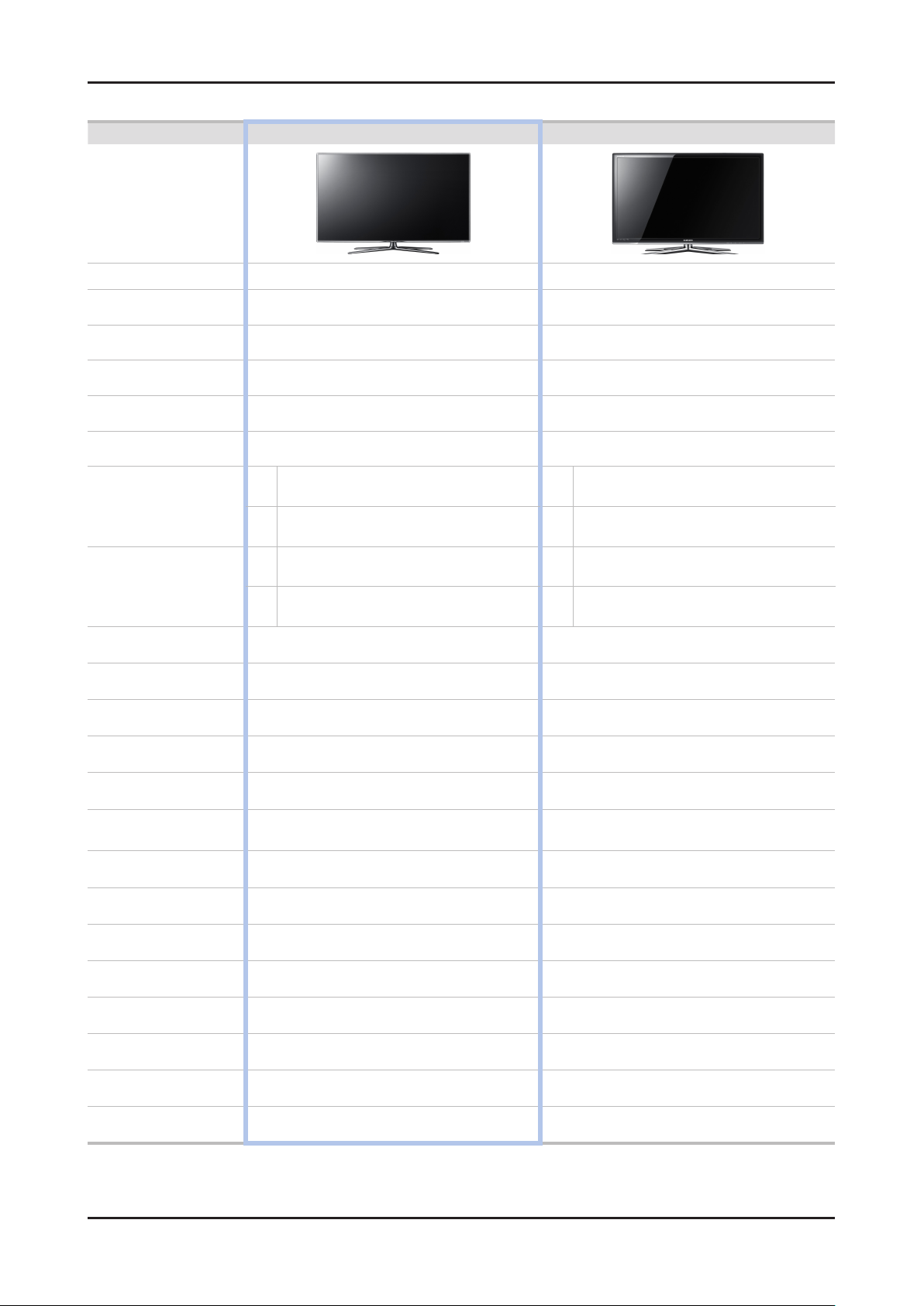
2-1-1. Model Comparison
Model UA7000L*
2. Product specications
Front view
Detail view
Front Color
All
All
All
All U-T-CL-M
Dimensions
W x D x H
(mm)
Weight
(lbs)
Panel Type
Internal Memory
DDR
Feature
Without Stnand 1041.1 29.7 599.4
46"
55"
46"
55"
With Stand 1041.1 276.5 607.5
Without Stnand 1232.6 29.7 707.2
With Stand 1232.6 309.3 789.7
Without Stnand 12.4
With Stand 14.3
Without Stnand 16.2
With Stand 18.6
All TFT LCD PANEL 240 Hz
All 128 Mbtye
All 768 Mbtye
All
3D, MOIP, SMART HUB, Allshare, Internet TV, Built-in Wi-Fi, Full Browser, Bluetooth
2-1

2-2
2. Product specications
2-1-2. Feature & Specications
Model UA46D7000L*
Feature
Digital-TV, RF, 4-HDMI, 1-Component, 2-A/V, 3-USB2.0(Media Play), D-SUB , LAN ሪ
Brightness : Mega Contrast ሪ
PIP(in HDMI 1, 2, 3, 4, Component 1, PC Mode and Sub picture is available only in TV mode(DTV/ATV)) ሪ
Dolby Digital+, SRS theater HD ሪ
Specications
Item Description
LCD Panel 46 inch HD 240 Hz
Scanning Frequency Horizontal : 67.5 KHz (typ)
Vertical : 60 Hz (typ)
Display Colors 16.7M color
Maximum resolution Horizontal : 1920 Pixels
Vertical : 1080 Pixels
Input Signal Analog 0.7 Vp-p ± 5% positive at 75Ω , internally terminated
Input Sync Signal H/V Separate, TTL, P. or N.
Maximum Pixel Clock rate 160 MHz
Active Display
Horizontal/Vertical
AC power voltage & Frequency AC 110 V ~ 120 V, 60 Hz
Power Consumption Under 150 W (Under 0.1 W, Stand by)
Dimensions Set
(W x D x H)
Weight Set
(lbs / kg)
TV System Tuning Frequency Synthesize (Refer to detailed Frequency Table)
Environmental Considerations Operating Temperature : 50˚F ~ 104˚F (10˚C ~ 40˚C)
Audio spec. - MAX Internal speaker Out : Right/Left(10 W)
40.08189 x 2.546063 inches (1018.08 (H) x 572.67 (V) mm)
1041.1 X 276.5 X 607.5 mm with stand
1041.1 X 29.7 X 599.4 mm without stand
14.3 kg_with stand
12.4 kg_without stand
System 1 PAL/SECAM/NIM/QAM/Cable tuner
Sound Dolby Digital+, SRS theater HD
Operating Humidity : 10% ~ 80%, non-condensing
Storage temperature : -13˚F ~ 113˚F (-25˚C ~ 45˚C)
Storage Humidity : 5% ~ 95%, non-condensing
- Equalizer : 5 Band
- Output Frequency : RF : 20 Hz ~ 15.4 kHz
AV/Componet/HDMI : 20 Hz ~ 20 kHz
Note: 3D, MOIP, Media Bridge, Allshare, Internet TV, Built-in Wi-Fi, Full Browser, Bluetooth

2-3
2. Product specications
Model UA55D7000L*
Feature
Digital-TV, RF, 4-HDMI, 1-Component, 1-A/V, 3-USB2.0(Media Play), D-SUB , LAN ሪ
Brightness : Mega Contrast ሪ
PIP(in HDMI 1, 2, 3, 4, Component 1, PC Mode and Sub picture is available only in TV mode(DTV/ATV)) ሪ
Dolby Digital+, SRS theater HD ሪ
Specications
Item Description
LCD Panel 55 inch HD 240 Hz
Scanning Frequency Horizontal : 67.5 KHz (typ)
Vertical : 60 Hz (typ)
Display Colors 16.7M color
Maximum resolution Horizontal : 1920 Pixels
Vertical : 1080 Pixels
Input Signal Analog 0.7 Vp-p ± 5% positive at 75Ω , internally terminated
Input Sync Signal H/V Separate, TTL, P. or N.
Maximum Pixel Clock rate 160 MHz
Active Display
Horizontal/Vertical
AC power voltage & Frequency AC 110 V ~ 120 V, 60 Hz
Power Consumption Under 160 W (Under 0.1 W, Stand by)
Dimensions Set
(W x D x H)
Weight Set
(lbs / kg)
TV System Tuning Frequency Synthesize (Refer to detailed Frequency Table)
Environmental Considerations Operating Temperature : 50˚F ~ 104˚F (10˚C ~ 40˚C)
Audio spec. - MAX Internal speaker Out : Right/Left(15 W)
47.622047 x 26.787402 inches (1209.6 (H) x 680.4(V) mm)
1232.6 X 309.3 X 789.7 mm with stand
1232.6 X 29.7 X 707.2 mm without stand
18.6 kg_with stand
16.2 kg_without stand
System 1 PAL/SECAM/NIM/QAM/Cable tuner
Sound Dolby Digital+, SRS theater HD
Operating Humidity : 10% ~ 80%, non-condensing
Storage temperature : -13˚F ~ 113˚F (-25˚C ~ 45˚C)
Storage Humidity : 5% ~ 95%, non-condensing
- Equalizer : 5 Band
- Output Frequency : RF : 20 Hz ~ 15.4 kHz
AV/Componet/HDMI : 20 Hz ~ 20 kHz
Note: 3D, MOIP, Media Bridge, Allshare, Internet TV, Built-in Wi-Fi, Full Browser, Bluetooth
2-4
2. Product specications
2-1-3. Spec Comparison to the Old Models
Model UD7X UC7W
Design
Display Type
Built-in Tuner O O
Resolution
LCD Panel TFT LCD Panel 240 Hz TFT LCD Panel 240 Hz
Screen Size
Picture ratio 16 : 9 16 : 9
Dimensions
(W x H x D)
Weight
(lbs / kg)
Contrast Ratio MEGA CR MEGA CR
Picture Enhancer DNIe (X5) Crystal Engine
Equalizer 5 Band 5 Band
46
55
46
55
41.27 x 10.89 x 26.89(inch)_with stand
41.27 x 1.01 x 23.87(inch)_without stand
48.8 x 12.2 x 31.13(inch)_with stand
48.8 x 1.16 x 28.11(inch)_without stand
31.75 Ibs (14.4 kg)_with stand
27.55 Ibs (12.5 kg)_without stand
35.5 Ibs (16.8 kg)_without stand
LED TV LED TV
1920 x 1080 1920 x 1080
46" / 55" 46" / 55"
43 x 11.99 x 28.6 (inch)_with stand
43 x 1.04 x 25.71 (inch)_without stand
50.52 x 11.99 x 32.90(inch)_with stand
50.52 x 1.04 x 30.0 (inch)_without stand
49.5lbs (22.5kg)_with stand
38.94 lbs(17.7kg)_without stand
60.28lbs (27.4kg)_with stand
48.84 lbs(22.2kg)_without stand
41 Ibs (18.6 kg)_with stand
46
55
46
55
Auto Volume Control O O
Surround Sound ThearterSurround HD ThearterSurround
Speaker Output
PIP O O
Double Window X X
Caption
Entertainment Mode X X
Game Mode O O
Energy Saving O O
Anynet+ O O
Antenna
10 W + 10 W (46")
15 W + 15 W (55")
O O
1(Cable/Air) 1(Cable/Air)
10 W + 10 W (46")
15 W + 15 W (55")

2-5
2. Product specications
2-2. Detail Factory Option
If you replace the main board with new one, please change the factory option as well. ※
The options you must change are "Type" and "Front Color".
2-2-1. UA7000L*
Model Name UA46D7000L* UA55D7000L*
Vendor AML AML
Panel
SMPS
1 Factory Reset BN94-04936F BN94-04936J
2 Type 46A2UF7E 55A2UF7E
3 Local set EA_**** EA_****
4 Model UD7000 UD7000
5 Tuner AUTO AUTO
6 DDR - -
7 Light Effect OFF OFF
8 Ch Table - -
9
10 Front Color U-W-Milky U-W-Milky
Country
CODE BN95-00439A BN95-00440A
SPEC LTJ460HQ01-V LTJ550HQ02-V
Vendor DYREL HANSOE
CODE BN44-00427B BN44-00428B
SPEC PD46B2_BDY PD55B2_BHS
AD_AU AD_AU

2-6
2. Product specications
2-3. New Functions Explanation
2-3-1. Smart Hub
'11 Smart Hub vs '10 Internet@TV
'11 Smart Hub
Concepts and Features Launcher : Internet TV, Media
Play, Content Button
Search All : Provides integrated search results for a
variety of areas
Full Browser : PC's Web browser, such as access to
common web site content and applications so you can
see
'10 Internet@TV
Internet TV, Media Player, content button
configured separately
Launcher - internet widget
Gallery -Free widget download / install
Horizontal / Vertical view modes
Internet@TV Button(Hot key on remote control)
Media. P Button(Hot key on remote control)
Comtent Button(Hot key on remote control)

2-7
2. Product specications
Smart Hub Concepts
Gateway to access all type of diverse content
It's all integrated to guide you to easier diverse entertainment choice•
Control your entertainment life with easy and simple user friends UI•
Access to driverse Apps that are adding every day•
Customize your TV, by App grouping & sorting to your taste•

2-8
2. Product specications
2-3-2. Full Browser
Concepts and Features
Full Browser ?
Using this App., you can contact the web site and contents just like web browser of PC.
1 3 42
65 987
1 Favorite
- Show the list of sites that user frequently accessed.(text list or thumbnail)
- User can export and import favorites list using USB.
2 History
- Show and record the list of the sites that user had accessed.
3 Window list
- It can show the 6 windows to the max.
- User can select window list to see the windows that opened.
4 Zooming
- User can zoom in/out the windows.
5 Tab mode
- User can focus data that linked using 4 direction button on internet websites.
6 Pointer mode
- If User select yellow color key on Tab mode, Change to pointer mode.
- User can select and control data that can not be selected on Tab mode( ex. Volume button on Flash contents) using
pointer that control by 4 direct button.
7 Reading tools
-
If user has a hard time reading because of small font size or advertisement, select the reading tool to display only text and image.
8 Clean site
- Users can access only to websites set as "Clean Site" for safety. (ex. children care)
This function can be set through the below path.
"Option" → "Setting" → Select "Clean site" When users try to first access, the password is "0000".
9 Private Browsing
- This function can be set throug the below path.
"Option" → "Setting" → Select "Private Browsing".
After setting this function, all accessing sites will be stored in the user's web history.
2-9
2. Product specications
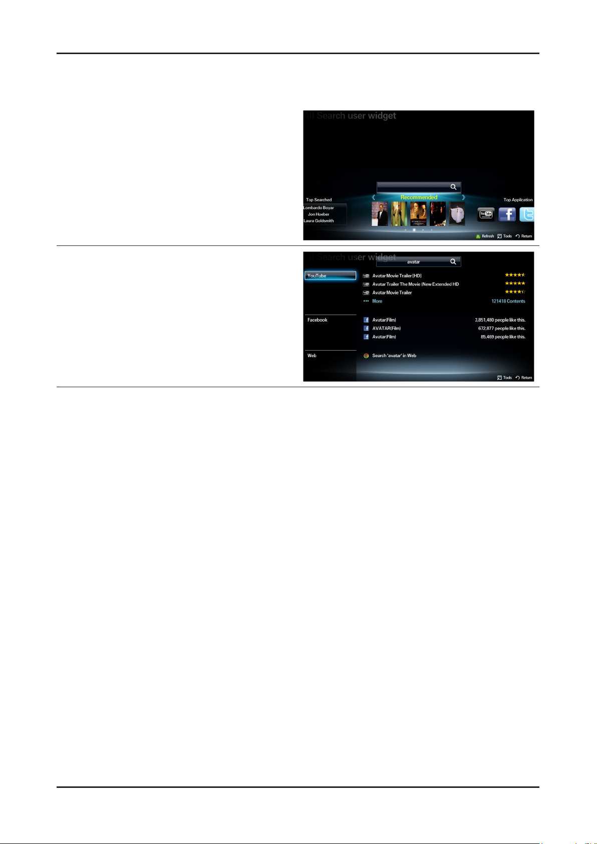
2-3-3. Seach all
Function
User can access the service using direct key on
remote control during TV viewing or using other App.
Supported four catecories
Your Movie: recommended movie or TV program
Top Application: popular Application list
Top Searched: popular searsh list
Search History
The application provides Web and SNS based search
engine.
YouTube
Facebook
Your Movie
Samsung Apps
AllShare
Web

2-10
2. Product specications
2-3-4. AllShare
About AllShare™
AllShare™ connects your TV and compatible Samsung mobile phones/ devices through a network. On your TV,
you can view call arrivals and SMS messages, and received by your mobile phones. In addition, you can play media
contents including videos, photos, and music saved on your mobile phones or the other devices (such as your PC)
by controlling them on the TV via the network. Additionally, you can use your TV for browsing web pages on your
mobile phones.
N For more information, visit “www.samsung.com” or contact the Samsung call center. Mobile devices may need
additional software installation. For details, refer to each device’s user’s guide.
Setting Up AllShare™
O MENU → Network → AllShare Settings → ENTERE
AllShare Settings01.
Media (On / Off) : Enables or disables the media function. When the media
function is on, you can control Media contents play using mobile phones or other
devices that support DLNA DMC.
Message (On / Off) : Enables or disables the message function. (for call arrivals,
and SMS messages received by your mobile phones)
Media / Message02.
Shows a list of mobile phones or connected devices which have been set up to use the Media or Message function
with this TV.
N The Media function is available in all devices which support DLNA DMC.
Allowed / Denied• : Allows/Blocks the devices.
Delete• : Deletes the devices from the list.
N This function only deletes the name of the device from the list. If the deleted device is turned on or tries to connect to the
TV, it may appear on the list again.
Using the Message Function03.
You can view call arrivals and SMS messages received by your mobile mobile phone, through the alarm window,
while watching TV.
N NOTE
To disable the alarm window, set • Message to Off in the AllShare Settings.
Whether • OK is selected or not selected after a message has appeared once, the message will be deleted from
the alarm window.
When a message from an unknown mobile phone is displayed, select the mobile phone in the • Message menu in
AllShare Settings, and then select Denied to block the phone.
Message View
If a new SMS message arrives while you are watching TV, the alarm window appears. If you select OK, the
contents of the message are displayed.
N You can congure the viewing settings for SMS messages on your mobile phones. For the procedures, refer to the mobile
phone manual.
N Some types of characters may be displayed as blank or broken characters.
Call Arrival Alarm
If a call arrives while you are watching TV, the alarm window appears.
Schedule Alarm
You can view scheduled events in the alarm window while you are watching TV.
N You can congure viewing settings for scheduled contents on your mobile phones. For the procedures, refer to the mobile
phone manual.
N Some special characters may be displayed as blank or broken characters.

2-11
2. Product specications
Using the Media Function04.
An alarm window appears informing you that media contents (videos, photos, music) sent from a mobile phone will
be displayed on your TV. The contents are played automatically 3 seconds after the alarm window appears. If you
press the RETURN or EXIT button when the alarm window appears, the media contents are not played.
N NOTE
The first time a device accesses your TV through the media function, a warning popup window appears. •
Press the ENTERE button to select Allow. This permits the phone to access the TV freely and use the Media
function to play content.
To turn off media contents transmissions from a mobile phone, set • Media to Off in the AllShare Settings.
Contents may not play on your TV depending on their resolution and format.•
The • ENTERE and l r buttons may not work depending on the type of media content.
Using the mobile device, you can control the media play. For details, refer to each mobile’s user’s guide.•

2-12
2. Product specications
AllShare™ setup and checklists
Problem Possible Solution
Deleted mobile phone list showing up
again.
Want to turn off the function of receiving
message from the mobile phone.
Want to turn off the function of receiving
Media from mobile phone or home
network devices on TV.
Want to add deleted mobile phone or
home network devices again.
Several same names of TV shows up on
mobile phone.
Messages/schedules/notications from
unknown mobile phone show up on TV.
SMS message notication shows up in
small window.
Received SMS message is not showing
up on TV.
[Menu > Application > Content View > AllShare™ > Message] •
Where need to block the added mobile phone or device again. Because deleted
device would be added again if that device turns on or attempt to approach.
One of the setup lists of AllShare™, you need to turn 'Message' list to 'Off'.•
One of the setup lists of AllShare™, you need to turn 'Media' list to 'Off'.•
Power on the deleted mobile phone or home network devices. •
Set up the network and activate the home network function, check the connection
at AllShare™.
At AllShare™ set up menu, change the name of the TV.•
[Menu > Application > Content View > AllShare™ > Message] •
Where You can block the unknown mobile phone.
Besides watching TV, If some other function is activating, SMS message will show •
up in small icon.
You need to nish the function and exit to Watching TV mode in order to display •
SMS message in large window.
Check if TV’s network setup is all right according to setup guide.•
Check if mobile phone’s network (Wi-Fi) is activated.•
Among the • AllShare™ setup lists , check if the Message is ‘on’.
Check if the mobile phone number is showing up on • AllShare™ message list.
Check if the TV’s showing up on mobile phone’s setup lists.•
Contents that play on mobile phone
doesn’t play on TV.
Suddenly TV display is changed,
unwanted movie/picture/music is playing
The name of the TV is not appearing
while try to play media on mobile phone.
Movie is not playing or disconnected. High resolution of Movie may not play when Wi-Fi network is not in good condition.•
Contents formats play on TV is exactly same as Media Play format. •
That means some contents may not play according to its resolution and format
Before the device play, Block the device at AllShare™ media list. •
Or press ‘return’ or ‘exit’ button of remote controller so that the device may not play.
Check the network of TV.•
Activate the network (Wi-Fi) of mobile phone and connect to home network .•
Check if the setup list of media on AllShare™ is ‘on’.•
Check if mobile phone is blocked on media list . If blocked, change it to permition.•

2-13
2. Product specications
Troubleshooting about new functions
Problem
AllShare (General)•
I see no device connected to AllShare.
I tried to play a video from my cell phone
using the Connected Home function on the
Samsung TV but the video would not display
on the TV.
A video that can be played on my cell phone
cannot be played on my TV.
I cannot resume playback of a video using
Connected Home.
When I play a video through Connected
Home, I get intermittent picture loss.
Possible Solution
To use a device connected to AllShare, the device must be connected to PC •
Share Manager which is the DLNA server for MediaPlay and to a cell phone that
has the Connected Home or Screen Share function which are found on Samsung
Smartphones.
Check that the PC Share Manager is enabled, the Samsung TV is set to allow •
connections and the ScreenShare function on the connected cell phone is enabled.
To use the cell phone’s Connected Home function, check that the shared folder is •
set and the Share mode is ‘On.’
When a video is transmitted from Connected Home to a TV for the rst time, the •
settings screen that allows transfer to a TV is displayed.
Check that the transfer was not set to be rejected on this settings screen. If you •
have set the cell phone to ‘Blocked’ in the ‘Media’ options of the AllShare settings,
please change the setting to ‘Unblocked’ and retry.
Please check the resolution and display format provided by MediaPlay of the TV.•
The resuming function is not supported for a video played on a cell phone.•
An 801.11b/g bandwidth network is used between a cell phone and a sharing •
device. There may be frequent buffering for HD quality videos, this also depends
on the condition of the wireless connection.
Please optimize your wireless Internet environment settings (avoid using wireless •
Internet or bluetooth altogether if possible) or lower the picture quality of the video.
AllShare (Notication)•
Can all devices with the DLNA function be
recognized through Notication?
Can I use all the services related to DLNA?
The notication screen that appears after
a device connects disappears within a few
seconds.
How can I access this connected device
again?
AllShare (ScreenShare Client)•
I cannot nd the RUIS on my cell phone.
Only Samsung software and devices with the DLNA server function can be •
recognized through Notication.
Presently, you can only use the services related to ScreenShare and MediaPlay. •
We will launch a new DLNA service in the future.
The DLNA Notication is only displayed when a device is rst connected to a TV. •
To access the device again, please use the AllShare menu.
Check that the cell phone is connected to the wireless sharing device correctly.1.
Check that the DTV is connected either using a network cable or wirelessly to the 2.
wireless sharing device correctly.
Conrm the IP address and subnet mask to ensure that the cell phone and DTV 3.
are connected to the same network.
Check that the RUIS on the cell phone is enabled.4.
If the RUIS on the cell phone is enabled, please disable it and then enable it again.5.

2-14
2. Product specications
Problem
AllShare (ScreenShare Server)•
I cannot nd the remote control service
provided by the ScreenShare Server from the
ScreenShare Client.
The DTV did not update after pressing
buttons on the remote control that uses the
remote control service on the ScreenShare
Client.
Possible Solution
Check that the ScreenShare Client device is correctly connected to the network of 1.
the sharing device that the DTV is connected to.
Run network test in the network setup menu and conrm that MAC Address, IP 2.
Address, Subnet, Gateway, DNS Server and Gateway Ping each shows a success
message.
In the network setup menu, check that the ScreenShare Client and ScreenShare 3.
Server are on the same subnet.
- You can conrm they are on the same subnet by checking the IP address,
subnet mask and gateway address of the TV and ScreenShare Client as follows:
- If the IP address of the DTV is 10.88.83.4 and the subnet mask is 255.255.255.0,
the rst six digits of the ScreenShare Client’s IP address must be the same
(10.88.83) as that of the DTV, and the subnet mask and gateway address must
be the same as the DTV.
- If the IP address of the DTV is 10.88.83.4 and the subnet mask is 255.255.0.0,
the rst four digits of the ScreenShare Client’s IP address must be the same
(10.88) as that of the DTV, and the subnet mask and gateway address must be
the same as the DTV.
Move from the Allshare screen to the Setup screen, and open the Setup menu to 4.
check if the ScreenShare Client is connected to the same ScreenShare Server as
the TV name shown in the Setup options.
Move from the Allshare screen to the Setup screen, and open ScreenShare to 5.
check that the device, ScreenShare Client, is found on the list at the right side and
is set to "Allowed."
Check that the TV is turned on. •
You cannot turn on the TV using the remote control service (on the ScreenShare)
when the TV is turned off.

2-15
2. Product specications
2-3-5. Media Play
Media Play
Functions that are not supported when connecting to a PC through a network:01.
- Sorting files by preference in the Photos, Music, and Videos folders.
- The � (REW) or μ (FF) button while a movie is playing.
- Divx DRM, Multi-audio, embedded captions are not supported.
When you use Media Play mode through a network connection, depending on the functions of the 02.
provided server
- The sorting method may vary.
- The scene search function may not be supported.
- The Play Continuously function, which resumes playing of a video, may not be supported.
- The Play Continuously function does not support multiple users. (It will have only memorized the point where the most recent user
stopped playing.)
- The ◄ or ► buttons may not work depending on the content information.
– If you experience any file stuttering issue while playing a video over a wireless network, we recommend using a wired network."
● Supported Subtitle Formats
Name File extension Format
MPEG-4 time-based text .ttxt XML
SAMI .smi HTML
SubRip .srt string-based
SubViewer .sub string-based
Micro DVD .sub or .txt string-based
● Supported Video Formats
File
Extention
*.avi
*.mkv
*.asf ASF
*.wmv ASF Window Media Video v9 1920 x 1080 6 ~ 30 25 WMA
*.mp4 MP4
*.3gp 3GPP
*.vro
*.mpg
*.mpeg
*.ts
*.tp
*.trp
Container Video Codec Resolution
Divx 3.11/4.x/5.1/6.0 1920 x 1080 6 ~ 30 8
AVI
MKV
VRO
VOB
PS
TS
XviD 1920 x 1080 6 ~ 30 8
H.264 BP/MP/HP 1920 x 1080 6 ~ 30 25
MPEG4 SP/ASP 1920 x 1080 6 ~ 30 8
Motion JPEG 640 x 480 6 ~ 30 8
Divx 3.11/4.x/5.1/6.0 1920 x 1080 6 ~ 30 8
XviD 1920 x 1080 6 ~ 30 8
H.264 BP/MP/HP 1920 x 1080 6 ~ 30 25
MPEG4 SP/ASP 1920 x 1080 6 ~ 30 8
Motion JPEG 640 x 480 6 ~ 30 8
H.264 BP/MP/HP 1920 x 1080 6 ~ 30 25
XVID 1920 x 1080 6 ~ 30 8
H.264 BP/MP/HP 1920 x 1080 6 ~ 30 25
MPEG4 SP/ASP 1920 x 1080 6 ~ 30 8
MPEG2 1920 x 1080 24/25/30 30
MPEG1 1920 x 1080 24/25/30 30
MPEG1 1920 x 1080 24/25/30 30
MPEG2 1920 x 1080 24/25/30 30
H.264 1920 x 1080 6 ~ 30 25
MPEG2 1920 x 1080 24/25/30 30
H.264 1920 x 1080 6 ~ 30 25
VC1 1920 x 1080 6 ~ 30 25
Frame rate
(fps)
Bit rate
(Mbps)
Audio Codec
MP3/AC3
/LPCM
/ADPCM
/DTS Core
MP3/AC3
/LPCM
/ADPCM
/WMA
MP3/ADPCM /AACMPEG4 SP/ASP 1920 x 1080 6 ~ 30 8
ADPCM/AAC
/HE-AAC
AC3/MPEG
/LPCM
AC3/MPEG
/LPCM/AAC
AC3/AAC
/MP3/DD+
/HE-AAC

2-16
2. Product specications
Other Restrictions03.
N NOTE
If there are problems with the contents of a codec, the codec will not be supported.•
If the information for a Container is incorrect and the le is in error, the Container will not be able to play correctly.•
Sound or video may not work if the contents have a standard bit rate/frame rate above the compatible Frame/sec listed in the •
table above.
Supports up to H.264, Level 4.1•
H.264 FMO / ASO / RS, VC1 SP / MP / AP L4 and •
AVCHD are not supported.
XVID, MPEG4 SP, ASP: •
– Below 1280 x 720: 60 frame max
– Above 1280 x 720: 30 frame max
GMC is not support.•
Video Decoder Audio Decoder
Supports up to WMA 7, 8, 9, STD, 9 PRO•
WMA 9 PRO is not supported the 2 channel excess multi •
channel or the lossless audio
WMA sampling rate 22050Hz mono is not supported. •
ReadlAudio 10 lossless is not supported

2-17
2. Product specications
2-3-6. 3D Display
What is 3D Display?
A system that display 3D images articially •
How ? • Using binocular time delay
1 Left eye recognizes left image, right eye recognizes
right image.
2 Human eyes be far away each other 65mm
horizontally.
So each eye feels a little bit of time delay of left and
right information.
Human brain merges those images and can feel
three-dimensional.
Side by side ◄
3D OSD terms
3D Format : There are several 3D formats existing on how to merge Left and Right images.
Format Input images explanation Input source notes
Frame Packing
Inserting Blink Active Space between Left and Right •
images.
* Full resolution : 1920 x 1080 x 2
(Left and Right each) + Blink = 1920 x 2205
HDMI 1.4 1. HDMI 1.4 standard format
2. Automatically activating
(Not in the menu or UI)
3. BD format
Top & Bottom
Side by Side
Line by Line
Vertical Stripe
Checker Board
Frame
Sequential
2D → 3D Extract Left and Right images articially from normal 2D contents input and show it in 3D. (a function of TV)
3D → 2D
Depth
L/R correction Switch the position of Left and Right images so that correspond with 3D glasses.
3D Disable
(3D off)
When watching 3D TV (input is 3D source) , if a viewer feels tired of watching 3D TV, a viewer can change the TV into 2D.
(In this case , TV only displays one of Left and Right images)
Only activating in ‘2D → 3D Mode’
Control the depth of 3D. 1~10 steps, Tiredness goes higher as depth goes higher.
‘3D off’ has below meanings according to present modes .
(1) In 2D → 3D Mode : coming back to 2D
In 1 frame, Left image on the upper half, Right image •
on the bottom half.
* Vertically half resolution
In 1 frame, Left image on the left half, Right image on •
the right half.
* Horizontally half resolution
In 1 frame, every horizontal line, Left and Right •
image in turn.
* Vertically half resolution
In 1 frame, every vertical line, Left and Right image •
in turn.
* Horizontally half resolution
In 1 frame, every pixel, Left and Right image in turn. •
* Half resolution both vertically and horizontally
Left And Right image in turn in every frame.•
Full resolution spatially but Half resolution timely. •
HDMI, USB,
DTV(VOD),
PC
HDMI, USB,
DTV(VOD),
PC
PC 1. MPEG encoding impossible
PC 1. MPEG encoding impossible
PC 1. MPEG encoding impossible
PC
3D Broadcasting Format
3D Broadcasting Format
2. Only in PC
2. Only in PC
2. Only in PC
(2) In 3D mode

2-18
2. Product specications
3D Supporting Formats
DTV
Top-Bottom
Side by Side
Line by line - - - -
Vertical Stripe - - - -
Frame Seq.
Checker BD - - - -
2D 3D
MPO
SAVE(SS.TB) - - - - - - - -
HDMI 1.4a - - - - - - - - -
M2TS(3D) - - - - - - - -
Over
720P
Over
720P
- - - -
- - - - - - -
Internet
VOD
All Resolution Over
All Resolution Over
ATV/AV Comp. A.PC HDMI USB_PC
720P -
720P -
All Resolution
Over
720P
Over
720P
Be Supported Only LED/PDP 7000/8000/9000(Genoa-P)
Over
720P
Over
720P
PC Resolution
PC Resolution
PC Resolution
PC Resolution
* 60Hz only
USB
(Photo)
All Resolution All Resolution
All Resolution All Resolution
- -
- -
- -
- -
All Resolution
N • : If the resolution is below 1920 x1080,PC Format(LL, VS, ChBD)and USB photo support only original size
• : The edge of the Side by Side and Top-Bottom images are processed by Black (only component)
• USB photo : If the resolution is below 1920x1080, L/R images must be placed in the center of the screen
3D Glasses Enhancement in 2011
3D Format : There are several 3D formats existing on how to merge Left and Right images.
Item RF Auto On / Off
USB
(Video)
-
All Resolution
All Resolution
Purpose
Improvement
Remarks
To avoid external IR nois interference No power key
Dual Direction
Communication
Wear glasses Turn on
Take off glasses Turn off
Automatically

2-19
2. Product specications
2-3-7. Built in Wi-Fi
Built in Wi-Fi
Gives more convenient set-up and optimize to use Ethernet.
Smart TV Accessory - Wireless Router01.
Easy Set-up & Optimized Solution for using Ethernet
• One Foot Connection
Establish a Wi-Fi connection to any compatible device placed within 25 cm distance
• USB configuration
Insert USB to router Insert USB to Samsung TV
Configurations is safely stored on USB drive and restored on TV
(Samsung Patent pending)
Network Settings (OFC, One Foot Connection
The One Foot Connection function lets you connect your Samsung TV automatically to Samsung wireless APs.
If your non-Samsung AP does not support One Foot Connection, you must connect using one of the other methods.
How to set up using One Foot Connection01.
Go to Network Settings screen. 1.
To enter it, follow the directions of Network Settings.
Select the One Foot Connection.2.
Place the AP in parallel with the Samsung Wireless LAN Adapter giving 3.
a gap no larger than 25 cm.
Wait until the connection is automatically established.4.
The network test screen appears, and network setting is done.5.
Place the AP in a desired location.6.
Network Settings (Plug & Access)
Plug & Access function lets you connect your Samsung wireless Router to Samsung TV easily by using USB memory. If
your non-Samsung AP does not support Plug & Access, you must connect using one of the other methods.
* You can check for equipment that supports Plug & Access on www.samsung.com.
How to set up using Plug & Access Function
Turn on the power of AP and TV. 1.
Insert USB memory stick into our Samsung wireless APs and checking AP’s LED status (blinking on).
Then take USB memory out and insert your USB memory into Samsung TV. 2.
Wait until the connection is automatically established.3.
If 4. Plug & Access does not connect your TV to your AP, a pop-up window appears on the screen notifying you of the failure. If you
want to try using Plug&Access again, reset the AP, disconnect the Samsung Wireless LAN Adapter and then try again from Step 1.
You can also choose one of the other connection setup methods.
The network test screen appears, and network setting is done.5.
Place the AP in a desired location.6.
If the AP settings change or you install a new AP, you must perform the 7. Plug & Access procedure again, beginning from Step 1.

2-20
2. Product specications
Problem
Network Setup•
How do I setup the network?
How do I check the network status?
In a network test over a wired connection,
the second items which include the IP
address, subnet, gateway and DNS server
fail.
In a network test over a wired connection,
the third item, gateway ping fails.
cannot connect to a wireless network.
Possible Solution
Click the [Menu] button and open [Setup] to select [Network]. •
Congure wired or wireless network settings.
For details, please refer to the IB.
Select [Menu] • [Setup] [Network] and run [Network Test] to see test results and
check the network status.
If the IP address, subnet mask and gateway address were typed in manually, •
check that valid values were entered.
(For example, 0.0.0.0 is not valid for an IP address, subnet mask or gateway
address.)
If the IP address the user entered in is invalid, change it to a valid IP address.
Check that the network cable is connected to the TV correctly.1.
If the TV is connected correctly, check whether the IP address is automatic or 2.
manual.
If the IP is automatic and connected to a sharing device, check the settings of the 3.
sharing device (AP) that is using a cable connection, or consult the corresponding
Internet service provider.
If the IP is manual, check if the IP address is entered correctly. 4.
(Here, the user should conrm if the manual IP address entered in is valid.)
If an encryption key must be entered in to connect to a sharing device, please 1.
check that the correct password set for the sharing device is entered.
Search surrounding sharing devices to see if there is a sharing device with the 2.
same SSID by selecting [Wireless Network Setup] and [Select Network].
If there is a sharing device with the same SSID, try to connect to this device.
If the IP address is set to automatic and you cannot connect to the sharing 3.
device using option 1 or 2, check the settings of the sharing device to see if the
DHCP server function on the sharing device is enabled. If disabled, activate the
function. (For details on how to set up the sharing device, see the manual for the
corresponding sharing device.)
If you still cannot connect to the sharing device after conrming options 1, 2 and 3, 4.
reset the sharing device and try again.
When using a wireless network, the user’s
wireless sharing device cannot connect to
the PBC (WPS).
The auto-conguring sharing device cannot
be connected to automatically through a
wireless dongle.
(Here, the user’s sharing device must
support auto-conguration.)
Although the TV is placed close to the AP
and the dongle is inserted into the TV, the
sharing device cannot be connected to using
auto-conguration.
Although the TV is placed close to the AP
and the dongle is inserted into the TV, the
sharing device cannot be connected to using
auto-conguration and a message that it is
connecting is displayed only.
Check if the sharing device of the user supports WPS. 1.
(Refer to the manual of the sharing device.)
Check if the user pressed the PBC button on the sharing device.2.
If there is another sharing device with WPS running nearby, a connection cannot 3.
be made. Please retry after 2 minutes.
Reset the sharing device and retry.4.
If the sharing device of the user is not Wi-Fi certied, it may not be able to connect 5.
using WPS.
Check if the sharing device of the user supports auto conguration. 1.
(For a list of sharing devices, refer to the IB or website.)
If the sharing device of the user supports auto conguration, place the sharing 2.
device as close as possible to the wireless dongle on the TV and try to re-establish
the connection. (Must be placed close to the TV to establish a connection.)
Select [Menu] • [Setup] [Network] and check if SWL is Off.
Check if the AP is not turned off during connection. •
If the AP is turned off, the TV will try to re-establish a connection for 2 minutes.

2-21
2. Product specications
Problem
Although the TV is placed close to the AP
and the dongle is inserted into the TV, the
sharing device cannot be connected to using
auto-conguration and a message that it is
connecting is displayed only.
In a network test over a wireless connection,
the second items which include the IP
address, subnet, gateway and DNS server
fail.
In a network test over a wireless connection,
the third item, gateway ping fails.
In a network test over a wireless connection,
the fourth item, Internet service test fails.
Possible Solution
If Samsung Wireless Link is On, a 5G-bandwidth wireless sharing device may not •
be found in a search (restriction).
If Samsung Wireless Link is Off or the product does not have the Samsung •
Wireless Link function, please retry searching to nd the sharing device. (May not
be found in a search depending on the settings of the wireless connection.)
If the IP address, subnet mask and gateway were typed in manually, check that •
valid values were entered. (For example, 0.0.0.0 is not valid for an IP address,
subnet mask or gateway address.)
If the IP address the user entered in is invalid, change it to a valid IP address.•
If the IP address is automatic and connected to a sharing device, check the 1.
settings of the sharing device (AP) that is using a cable connection, or consult the
corresponding Internet service provider.
If the IP address is manual, check that the IP address is entered in correctly. 2.
(Here, the user should conrm if the manual IP entered in is valid.)
Please consult the corresponding Internet service provider (an Internet network •
service provider the user has subscribed to such as KT).

2. Product specications
2-4. Accessories
Product Description Code. No Remark
Warranty Card /
Registration Card /
Safety Guide Manual
(Not available in all location)
Holder-Wire stand BN61-05491A
-
Holder-Ring (4ea) BN61-07295A
AV Adaptor BN39-01154H
Component Gender BN39-01154W
Samsung Electronics
Service center
2-22

3. Disassembly and Reassemble
3. Disassembly and Reassembly
This section of the service manual describes the disassembly and reassembly procedures for the LED TV.
WARNING: This LED TV contains electrostatically sensitive devices. Use caution when handling these components.
3-1. Disassembly and Reassembly
Cautions: 1. Disconnect the LED TV from the power source before disassembly.
2. Follow these directions carefully; never use metal instruments to pry apart the cabinet.
Description Picture Description
Place TV face down on cushioned table.
1
Remove screws from the Stand.
Remove stand.
Screws
6001-002621
(M4, L8, Tapping)
Remove the screws of rear-cover.
2
6001-002621
(M4, L8, Tapping)
3-1

3-2
3. Disassembly and Reassemble
Description Picture Description
Lift up and remove the rear-cover.
3
* Caution : Becareful when you lift up the
rear-cover, It’s really sharp.
Remove the screws of middle-cover.
4
Lift up and remove the middle-cover.
5
Screws
6001-002621
(M4, L8, Tapping)
* Caution: Remove the function cable
before removing the middle
cover.
- Rear view of 46" / 55"
 Loading...