

Page 1
LED TV
Chassis : U85A
Model : UA32F45*0A*
UA**F53*0A*
UA**F55**A*
SERVICE
LED TV Contents
1. Precautions
2. Product specications
3. Disassembly and Reassembly
4. Troubleshooting
5. Wiring Diagram
Manual
UA**F5500A*
Page 2

Contents
1. Precautions ...................................................................................................................1-1
1-1. Safety Precautions ..............................................................................................................1-1
1-2. Servicing Precautions ..........................................................................................................1-3
1-3. Static Electricity Precautions ...............................................................................................1-4
1-4. Installation Precautions .......................................................................................................1-5
2. Product Specications.................................................................................................2-1
2-1. Product Information .............................................................................................................2-1
2-2. Accessories .........................................................................................................................2-8
3. Disassembly and Reassembly ....................................................................................3-1
3-1. Disassembly and Reassembly ............................................................................................3-1
3-2. Assy Board P-Jog Switch & Ir ..............................................................................................3-6
3-3. Disassembly(PTC) ...............................................................................................................3-8
4. Troubleshooting ...........................................................................................................4-1
4-1. Troubleshooting ................................................................................................................... 4-1
4-2. How to Check Fault Symptom .............................................................................................4-3
4-3. Factory Mode Adjustments ................................................................................................ 4-21
4-4. White Balance ...................................................................................................................4-37
4-5. White Ratio (Balance) Adjustment .....................................................................................4-40
4-6. Detail Specications ..........................................................................................................4-42
4-7. Software Upgrade ............................................................................................................ 4-115
4-8. Rear Cover Dimension ....................................................................................................4-118
5. Wiring Diagram .............................................................................................................5-1
5-1. Wiring Diagram .................................................................................................................... 5-1
5-2. Connector ...........................................................................................................................5-2
5-3. Connector Functions ...........................................................................................................5-6
5-4. Cables .................................................................................................................................5-7
Page 3

This Service Manual is a property of Samsung Electronics Co.,Ltd.
Any unauthorized use of Manual can be punished under applicable
International and/or domestic law.
© 2013 Samsung Electronics Co.,Ltd.
All rights reserved.
Printed in Korea
Page 4
1. Precautions
1. Precautions
1-1. Safety Precautions
Follow these safety, servicing and ESD precautions to prevent damage and to protect against potential hazards such as
electrical shock.
1-1-1. Warnings
For continued safety, do not attempt to modify the circuit board.
WARNING
1-1-2. Servicing the LED TV
When servicing the LED TV, Disconnect the AC line cord from the AC outlet.1.
It is essential that service technicians have an accurate voltage meter available at all times. Check the calibration of this 2.
meter periodically.
1-1-3. Fire and Shock Hazard
Before returning the monitor to the user, perform the following safety checks:
Inspect each lead dress to make certain that the leads are not pinched or that hardware is not lodged between the 1.
chassis and other metal parts in the monitor.
Inspect all protective devices such as nonmetallic control knobs, insulating materials, cabinet backs, adjustment and 2.
compartment covers or shields, isolation resistorcapacitor networks, mechanical insulators, etc.
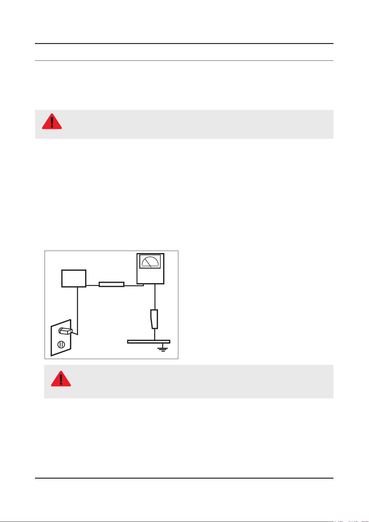
Leakage Current Hot Check:3.
Disconnect the AC power and DC power jack before servicing.
(READING SHOULD)
DEVICE
UNDER
TEST
ALSO TEST WITH
PLUG REVERSED
(USING AC ADAPTER
PLUG AS REQUIRED)
NOT BE ABOVE 0.5mA
2-WIRE CORD
TEST ALL
EXPOSED METAL
SURFACES
LEAKAGE
CURRENT
TESTER
EARTH
GROUND
Do not use an isolation transformer during this test.
Use a leakage current tester or a metering system that complies with American National Standards
WARNING
Institute (ANSI C101.1, Leakage Current for Appliances), and Underwriters Laboratories (UL
Publication UL1410, 59.7).
With the unit completely reassembled, plug the AC line cord directly into a 120V AC outlet. With the unit’s AC switch rst 4.
in the ON position and then OFF, measure the current between a known earth ground (metal water pipe, conduit, etc.)
and all exposed metal parts, including: metal cabinets, screwheads and control shafts.
The current measured should not exceed 0.5 milliamp.
Reverse the power-plug prongs in the AC outlet and repeat the test.
1-1
Page 5

1-2
1. Precautions
1-1-4. Product Safety Notices
Some electrical and mechanical parts have special safetyrelated characteristics which are often not evident from visual
inspection. The protection they give may not be obtained by replacing them with components rated for higher voltage,
wattage, etc. Parts that have special safety characteristics are identied by
replacement that does not have the same safety characteristics as the recommended replacement part might create
shock, re and/or other hazards. Product safety is under review continuously and new instructions are issued whenever
appropriate.
on schematics and parts lists. A substitute
Page 6

1-3
1. Precautions
1-2. Servicing Precautions
An electrolytic capacitor installed with the wrong polarity might explode.
WARNING
Before servicing units covered by this service manual, read and follow the Safety Precautions section of
CAUTION
NOTE
1-2-1. General Servicing Precautions
Always unplug the unit’s AC power cord from the AC power source and disconnect the DC Power Jack before 1.
attempting to: (a) remove or reinstall any component or assembly, (b) disconnect PCB plugs or connectors, (c) connect
a test component in parallel with an electrolytic capacitor.
Some components are raised above the printed circuit board for safety. An insulation tube or tape is sometimes used. 2.
The internal wiring is sometimes clamped to prevent contact with thermally hot components. Reinstall all such elements
to their original position.
After servicing, always check that the screws, components and wiring have been correctly reinstalled. Make sure that 3.
the area around the serviced part has not been damaged.
Check the insulation between the blades of the AC plug and accessible conductive parts (examples: metal panels, input 4.
terminals and earphone jacks).
Insulation Checking Procedure: Disconnect the power cord from the AC source and turn the power switch ON. Connect 5.
an insulation resistance meter (500 V) to theblades of the AC plug. The insulation resistance between each blade of the
AC plug and accessible conductive parts (see above) should be greater than 1 megohm.
Always connect a test instrument’s ground lead to the instrument chassis ground before connecting the positive lead; 6.
always remove the instrument’s ground lead last.
this manual.
If unforeseen circumstances create conict between the following servicing precautions and any of the
safety precautions, always follow the safety precautions.
Page 7

1-4
1. Precautions
1-3. Static Electricity Precautions
Some semiconductor (solid state) devices can be easily damaged by static electricity. Such components are commonly
called Electrostatically Sensitive Devices (ESD). Examples of typical ESD are integrated circuits and some eld-effect
transistors. The following techniques will reduce the incidence of component damage caused by static electricity.
Immediately before handling any semiconductor components or assemblies, drain the electrostatic charge from your 1.
body by touching a known earth ground. Alternatively, wear a discharging wrist-strap device. To avoid a shock hazard,
be sure to remove the wrist strap before applying power to the monitor.
After removing an ESD-equipped assembly, place it on a conductive surface such as aluminum foil to prevent 2.
accumulation of an electrostatic charge.
Do not use freon-propelled chemicals. These can generate electrical charges sufcient to damage ESDs.3.
Use only a grounded-tip soldering iron to solder or desolder ESDs.4.
Use only an anti-static solder removal device. Some solder removal devices not classied as “anti-static” can generate 5.
electrical charges sufcient to damage ESDs.
Do not remove a replacement ESD from its protective package until you are ready to install it. Most replacement ESDs 6.
are packaged with leads that are electrically shorted together by conductive foam, aluminum foil or other conductive
materials.
Immediately before removing the protective material from the leads of a replacement ESD, touch the protective material 7.
to the chassis or circuit assembly into which the device will be installed.
Be sure no power is applied to the chassis or circuit and observe all other safety precautions.
CAUTION
Minimize body motions when handling unpackaged replacement ESDs. Motions such as brushing clothes together, or 8.
lifting your foot from a carpeted oor can generate enough static electricity to damage an ESD.
Page 8

1-5
1. Precautions
1-4. Installation Precautions
For safety reasons, more than a people are required for carrying the product.1.
Keep the power cord away from any heat emitting devices, as a melted covering may cause re or electric shock.2.
Do not place the product in areas with poor ventilation such as a bookshelf or closet. The increased internal temperature 3.
may cause re.
Bend the external antenna cable when connecting it to the product. This is a measure to protect it from being exposed 4.
to moisture. Otherwise, it may cause a re or electric shock.
Make sure to turn the power off and unplug the power cord from the outlet before repositioning the product. Also check 5.
the antenna cable or the external connectors if they are fully unplugged. Damage to the cord may cause re or electric
shock.
Keep the antenna far away from any high-voltage cables and install it rmly. Contact with the highvoltage cable or the 6.
antenna falling over may cause re or electric shock.
When installing the product, leave enough space (0.4m) between the product and the wall for ventilation purposes. 7.
A rise in temperature within the product may cause re.
If an equipment is provided with a replaceable battery, and if replacement by an incorrect type could result in an 8.
explosion (for example, with some lithium batteries), the following applies:
Risk of explosion if battery is replaced by an incorrect type dispose of used batteries according to •
the instructions.
Do not dispose of batteries in a re.•
Do not short circuit, disassemble or overheat the batteries.•
CAUTION
Danger of explosion if battery is incorrectly replaced. Replace only with the same or equivalent •
type.
Do not be exposed to excessive heat such as sunshine, re or the like.•
Page 9
2. Product Specications
2-1. Product Information
2-1-1. Model Comparison
Model UE**F5500
2. Product specications
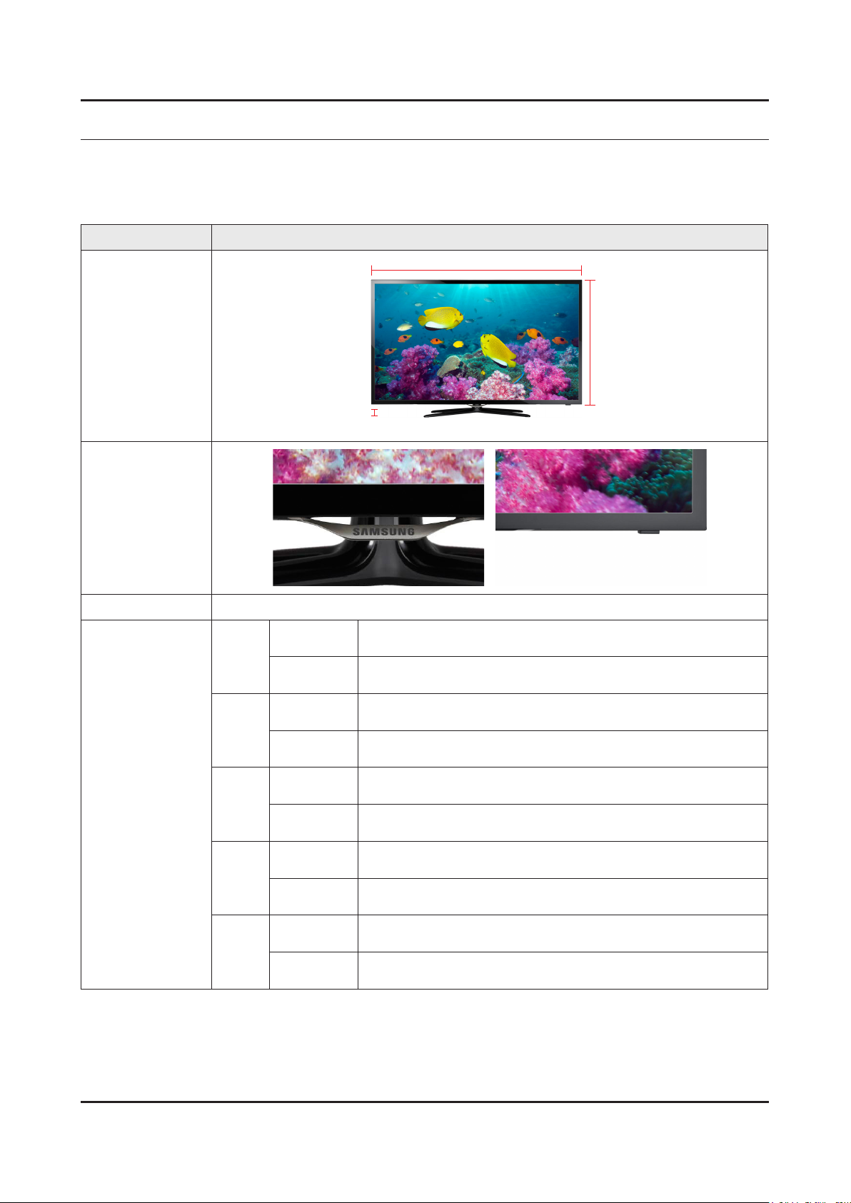
W
Front View
D
Detail View
Front Color Black (Panel)
Set with
Stand
Set without
Stand
Set with
Stand
Set without
Stand
Set with
Stand
Set without
Stand
Set with
Stand
Set without
Stand
Set with
Stand
Set without
Stand
738.0 x 509.6 x 265.0 mm / 29.1 x 20.1 x 10.4 inches
928.2 x 615.5 x 265.0 mm / 36.5 x 24.2 x 10.4 inches
1059.6 x 700.0 x 307.3 mm / 41.7 x 27.6 x 12.1 inches
1059.6 x 626.2 x 49.4 mm / 41.7 x 24.7 x 1.9 inches
1135.4 x 741.8 x 307.3 mm / 44.7 x 29.2 x 12.2 inches
1135.4 x 668.0 x 49.8 mm / 44.7 x 26.3 x 2.0 inches
Dimensions
(W x H x D)
32F45
32F53
32F55
40F53
40F55
46F53
46F55
50F55
* W : Width H : High D : Depth
750.9 x 476.9 x 207.8 mm / 29.6 x 18.8 x 8.2 inches
750.9 x 456.6 x 59.3 mm / 29.6 x 18.0 x 2.3 inches
738.0 x 445.4 x 49.0 mm / 29.1 x 17.5 x 1.9 inches
928.2 x 552.3 x 49.4 mm / 36.5 x 21.7 x 1.9 inches
H
2-1
Page 10
2-2
2. Product specications
Set with
32F45
32F53
32F55
Weight
Panel Type Anti Glare
Internal Memory 4 GByte
40F53
40F55
46F53
46F55
50F55
Stand
Set without
Stand
Set with
Stand
Set without
Stand
Set with
Stand
Set without
Stand
Set with
Stand
Set without
Stand
Set with
Stand
Set without
Stand
5.6 kg / 12.3 lbs
5.3 kg / 11.7 lbs
5.7 kg / 12.6 lbs
5.0 kg / 11.0 lbs
8.9 kg / 19.6 lbs
8.0 kg / 17.6 lbs
11.5 kg / 25.4 lbs
10.8 kg / 23.8 lbs
14.7 kg / 32.4 lbs
13.0 kg / 28.7 lbs
DDR 1 GByte
Feature Smart TV
Page 11
2-3
2. Product specications
2-1-2. Feature & Specications
Model UA32F55**A* / UA32F5300A* (M or W: DVB-T, K: DVB-T2, R: READY)
Feature
Digital-TV, RF, 3-HDMI, 1-Component, 1-A/V, 2-USB2.0, LAN•
Brightness : 300 cd/m•
Dynamic Contrast Ratio : Mega Contrast•
Response Time : 6.5 ms•
CMR : 120•
Item Description
LCD Panel 32 inch FHD 60Hz
Scanning Frequency Horizontal : 60 kHz ~ 73 kHz (Automatic)
Display Colors 16.7 M colors
Maximum Resolution Horizontal : 1920 Pixels
2
Specications
Vertical : 47 Hz ~ 63 Hz (Automatic)
Vertical : 1080 Pixels
Input Signal Analog 0.7 Vp-p ± 5% positive at 75Ω, internally terminated
Input Sync Signal H/V Separate, TTL, P. or N.
Maximum Pixel Clock Rate 74.25 MHz
Active Display (H x V)*
* Horizontal x Vertical
698.4(H) X 392.9(V) (mm) / 27.5(H) X 15.5(V) (inches)
AC Power Voltage & Frequency AC 220 V ~ 240 V / AC 100 V ~ 240 V, 50 Hz / 60 Hz
Power Consumption 86 / 85 W (Under 0.3 W, Stand by)
Dimensions Set (W x H x D)*
* Width x High x Depth
Set with Stand 738.0 x 509.6 x 265.0 mm / 29.1 x 20.1 x 10.4 inches
Set without Stand 738.0 x 445.4 x 49.0 mm / 29.1 x 17.5 x 1.9 inches
Weight Set with Stand 5.7 kg / 12.6 lbs
Set without Stand 5.0 kg / 11.0 lbs
TV System Tuning Frequency Synthesize (Refer to detailed Frequency Table)
System DVB-T/C/T2C(depend on country), PAL , SECAM , NT4.43
Sound PAL-B/G/I/D/K, Nicam, Dolby Digital Plus/Pulse
Environmental Considerations Operating Temperature: 50˚F ~ 104˚F (10˚C ~ 40˚C)
Operating Humidity: 10% ~ 80%, non-condensing
Storage Temperature: -4˚F ~ 113˚F (-20˚C ~ 45˚C)
Storage Humidity: 5% ~ 95%, non-condensing
Audio Specications MAX Internal Audio Output Power : Each 10 W(Left/Right)
Equalizer : 5 Band
Output Frequency :
RF : 20 Hz ~ 15.4 kHz•
AV/Componet/HDMI : 20 Hz ~ 20 kHz•
Note : Dolby Digital Plus/Pulse, USB2.0, Film mode, Energy Saving, Eco sensor, SmartTV
Page 12

2-4
2. Product specications
Model UA40F55**A* / UA40F53**A* (M or W: DVB-T, K: DVB-T2, R: READY)
Feature
Digital-TV, RF, 3-HDMI, 1-Component, 1-A/V, 2-USB2.0, LAN•
Brightness : 300 cd/m•
2
Dynamic Contrast Ratio : Mega Contrast•
Response Time : 6.5 ms•
CMR : 100•
Specications
Item Description
LCD Panel 40 inch FHD 60Hz
Scanning Frequency Horizontal : 60 kHz ~ 73 kHz (Automatic)
Vertical : 47 Hz ~ 63 Hz (Automatic)
Display Colors 16.7 M colors
Maximum Resolution Horizontal : 1920 Pixels
Vertical : 1080 Pixels
Input Signal Analog 0.7 Vp-p ± 5% positive at 75Ω, internally terminated
Input Sync Signal H/V Separate, TTL, P. or N.
Maximum Pixel Clock Rate 74.25 MHz
Active Display (H x V)*
* Horizontal x Vertical
885.6(H) X 498.2(V) (mm) / 34.9(H) X 19.6(V) (inches)
AC Power Voltage & Frequency AC 220 V ~ 240 V / AC 100 V ~ 240 V, 50 Hz / 60 Hz
Power Consumption 115 / 117 W (Under 0.3 W, Stand by)
Dimensions Set (W x H x D)*
* Width x High x Depth
Set with Stand 928.2 x 615.5 x 265.0 mm / 36.5 x 24.2 x 10.4 inches
Set without Stand 928.2 x 552.3 x 49.4 mm / 36.5 x 21.7 x 1.9 inches
Weight Set with Stand 8.9 kg / 19.6 lbs
Set without Stand 8.0 kg / 17.6 lbs
TV System Tuning Frequency Synthesize (Refer to detailed Frequency Table)
System DVB-T/C/T2C(depend on country), PAL , SECAM , NT4.43
Sound PAL-B/G/I/D/K, Nicam, Dolby Digital Plus/Pulse
Environmental Considerations Operating Temperature: 50˚F ~ 104˚F (10˚C ~ 40˚C)
Operating Humidity: 10% ~ 80%, non-condensing
Storage Temperature: -4˚F ~ 113˚F (-20˚C ~ 45˚C)
Storage Humidity: 5% ~ 95%, non-condensing
Audio Specications MAX Internal Audio Output Power : Each 10 W(Left/Right)
Equalizer : 5 Band
Output Frequency :
RF : 20 Hz ~ 15.4 kHz•
AV/Componet/HDMI : 20 Hz ~ 20 kHz•
Note : Dolby Digital Plus/Pulse, USB2.0, Film mode, Energy Saving, Eco sensor, SmartTV
Page 13
2-5
2. Product specications
Model UA46F55**A* / UA46F53**A* (M or W: DVB-T, K: DVB-T2, R: READY)
Feature
Digital-TV, RF, 3-HDMI, 1-Component, 1-A/V, 2-USB2.0, LAN•
Brightness : 300 cd/m•
2
Dynamic Contrast Ratio : Mega Contrast•
Response Time : 6.5 ms•
CMR : 100•
Specications
Item Description
LCD Panel 46 inch FHD 60Hz
Scanning Frequency Horizontal : 60 kHz ~ 73 kHz (Automatic)
Vertical : 47 Hz ~ 63 Hz (Automatic)
Display Colors 16.7 M colors
Maximum Resolution Horizontal : 1920 Pixels
Vertical : 1080 Pixels
Input Signal Analog 0.7 Vp-p ± 5% positive at 75Ω, internally terminated
Input Sync Signal H/V Separate, TTL, P. or N.
Maximum Pixel Clock Rate 74.25 MHz
Active Display (H x V)*
* Horizontal x Vertical
1018.1(H) X 572.7(V) (mm) / 40.1(H) X 22.5(V) (inches)
AC Power Voltage & Frequency AC 220 V ~ 240 V / AC 100 V ~ 240 V, 50 Hz / 60 Hz
Power Consumption 117 / 119 W (Under 0.3 W, Stand by)
Dimensions Set (W x H x D)*
* Width x High x Depth
Set with Stand 1059.6 x 700.0 x 307.3 mm / 41.7 x 27.6 x 12.1 inches
Set without Stand 1059.6 x 626.2 x 49.4 mm / 41.7 x 24.7 x 1.9 inches
Weight Set with Stand 11.5 kg / 25.4 lbs
Set without Stand 10.8 kg / 23.8 lbs
TV System Tuning Frequency Synthesize (Refer to detailed Frequency Table)
System DVB-T/C/T2C(depend on country), PAL , SECAM , NT4.43
Sound PAL-B/G/I/D/K, Nicam, Dolby Digital Plus/Pulse
Environmental Considerations Operating Temperature: 50˚F ~ 104˚F (10˚C ~ 40˚C)
Operating Humidity: 10% ~ 80%, non-condensing
Storage Temperature: -4˚F ~ 113˚F (-20˚C ~ 45˚C)
Storage Humidity: 5% ~ 95%, non-condensing
Audio Specications MAX Internal Audio Output Power : Each 10 W(Left/Right)
Equalizer : 5 Band
Output Frequency :
RF : 20 Hz ~ 15.4 kHz•
AV/Componet/HDMI : 20 Hz ~ 20 kHz•
Note : Dolby Digital Plus/Pulse, USB2.0, Film mode, Energy Saving, Eco sensor, SmartTV
Page 14

2-6
2. Product specications
Model UA50F55**A* (M or W: DVB-T, K: DVB-T2, R: READY)
Feature
Digital-TV, RF, 3-HDMI, 1-Component, 1-A/V, 2-USB2.0, LAN•
Brightness : 300 cd/m•
2
Dynamic Contrast Ratio : Mega Contrast•
Response Time : 6.5 ms•
CMR : 100•
Specications
Item Description
LCD Panel 50 inch FHD 60Hz
Scanning Frequency Horizontal : 60 kHz ~ 73 kHz (Automatic)
Vertical : 47 Hz ~ 63 Hz (Automatic)
Display Colors 16.7 M colors
Maximum Resolution Horizontal : 1920 Pixels
Vertical : 1080 Pixels
Input Signal Analog 0.7 Vp-p ± 5% positive at 75Ω, internally terminated
Input Sync Signal H/V Separate, TTL, P. or N.
Maximum Pixel Clock Rate 74.25 MHz
Active Display (H x V)*
* Horizontal x Vertical
1023.0(H) X 577.6(V) (mm) / 40.3(H) X 22.7(V) (inches)
AC Power Voltage & Frequency AC 220 V ~ 240 V / AC 100 V ~ 240 V, 50 Hz / 60 Hz
Power Consumption 139 / 143 W (Under 0.3 W, Stand by)
Dimensions Set (W x H x D)*
* Width x High x Depth
Set with Stand 1135.4 x 741.8 x 307.3 mm / 44.7 x 29.2 x 12.2 inches
Set without Stand 1135.4 x 668.0 x 49.8 mm / 44.7 x 26.3 x 2.0 inches
Weight Set with Stand 14.7 kg / 32.4 lbs
Set without Stand 13.0 kg / 28.7 lbs
TV System Tuning Frequency Synthesize (Refer to detailed Frequency Table)
System DVB-T/C/T2C(depend on country), PAL , SECAM , NT4.43
Sound PAL-B/G/I/D/K, Nicam, Dolby Digital Plus/Pulse
Environmental Considerations Operating Temperature: 50˚F ~ 104˚F (10˚C ~ 40˚C)
Operating Humidity: 10% ~ 80%, non-condensing
Storage Temperature: -4˚F ~ 113˚F (-20˚C ~ 45˚C)
Storage Humidity: 5% ~ 95%, non-condensing
Audio Specications MAX Internal Audio Output Power : Each 10 W(Left/Right)
Equalizer : 5 Band
Output Frequency :
RF : 20 Hz ~ 15.4 kHz•
AV/Componet/HDMI : 20 Hz ~ 20 kHz•
Note : Dolby Digital Plus/Pulse, USB2.0, Film mode, Energy Saving, Eco sensor, SmartTV
Page 15
2-7
2. Product specications
Model UA32F45**A* (M or W: DVB-T, K: DVB-T2, R: READY)
Feature
Digital-TV, RF, 3-HDMI, 1-Component, 1-A/V, 2-USB2.0, LAN•
Brightness : 300 cd/m•
2
Dynamic Contrast Ratio : Mega Contrast•
Response Time : 6.5 ms•
CMR : 120•
Specications
Item Description
LCD Panel 32 inch FHD 60Hz
Scanning Frequency Horizontal : 60 kHz ~ 73 kHz (Automatic)
Vertical : 47 Hz ~ 63 Hz (Automatic)
Display Colors 16.7 M colors
Maximum Resolution Horizontal : 1366 Pixels
Vertical : 768 Pixels
Input Signal Analog 0.7 Vp-p ± 5% positive at 75Ω, internally terminated
Input Sync Signal H/V Separate, TTL, P. or N.
Maximum Pixel Clock Rate 74.25 MHz
Active Display (H x V)*
* Horizontal x Vertical
703.4(H) X 397.8(V) (mm) / 27.7(H) X 15.7(V) (inches)
AC Power Voltage & Frequency AC 220 V ~ 240 V / AC 100 V ~ 240 V, 50 Hz / 60 Hz
Power Consumption 68 / 70 W (Under 0.3 W, Stand by)
Dimensions Set (W x H x D)*
* Width x High x Depth
Set with Stand 750.9 x 476.9 x 207.8 mm / 29.6 x 18.8 x 8.2 inches
Set without Stand 750.9 x 456.6 x 59.3 mm / 29.6 x 18.0 x 2.3 inches
Weight Set with Stand 5.6 kg / 12.3 lbs
Set without Stand 5.3 kg / 11.7 lbs
TV System Tuning Frequency Synthesize (Refer to detailed Frequency Table)
System DVB-T/C/T2C(depend on country), PAL , SECAM , NT4.43
Sound PAL-B/G/I/D/K, Nicam, Dolby Digital Plus/Pulse
Environmental Considerations Operating Temperature: 50˚F ~ 104˚F (10˚C ~ 40˚C)
Operating Humidity: 10% ~ 80%, non-condensing
Storage Temperature: -4˚F ~ 113˚F (-20˚C ~ 45˚C)
Storage Humidity: 5% ~ 95%, non-condensing
Audio Specications MAX Internal Audio Output Power : Each 10 W(Left/Right)
Equalizer : 5 Band
Output Frequency :
RF : 20 Hz ~ 15.4 kHz•
AV/Componet/HDMI : 20 Hz ~ 20 kHz•
Note : Dolby Digital Plus/Pulse, USB2.0, Film mode, Energy Saving, SmartTV
Page 16
2. Product specications
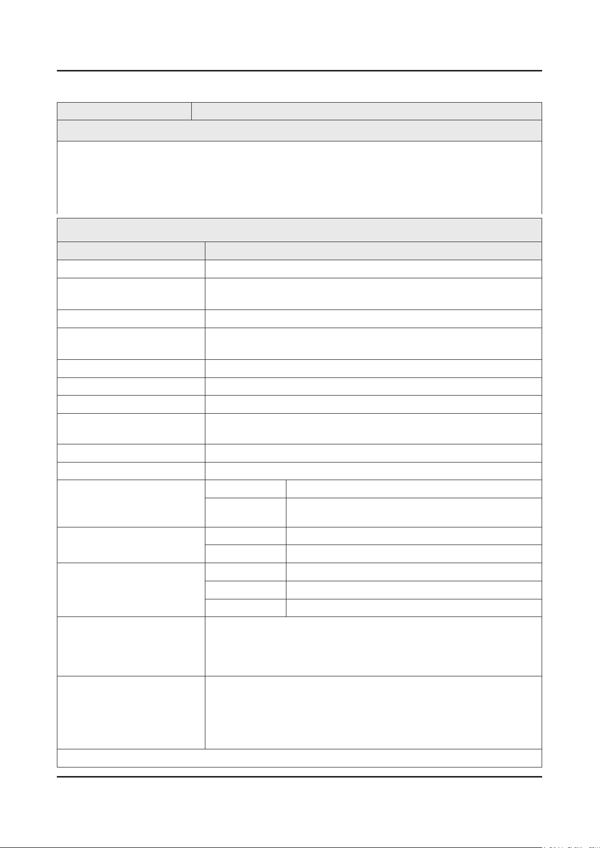
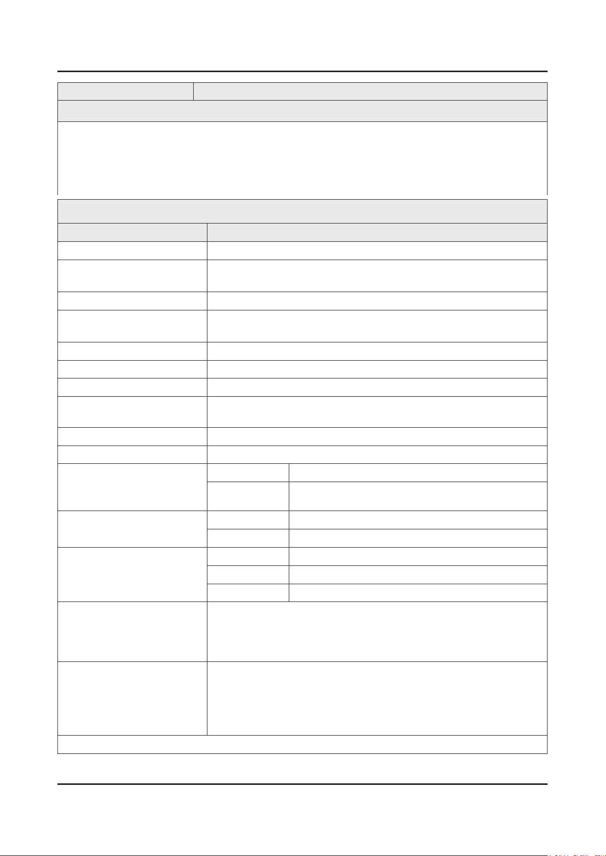
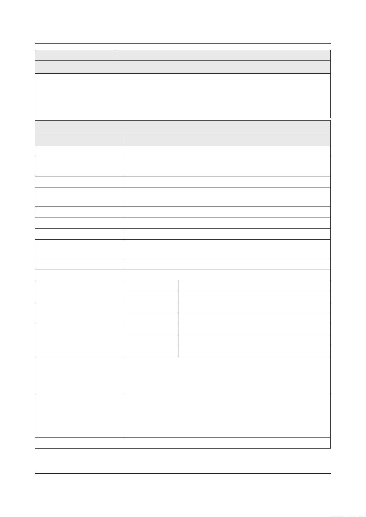
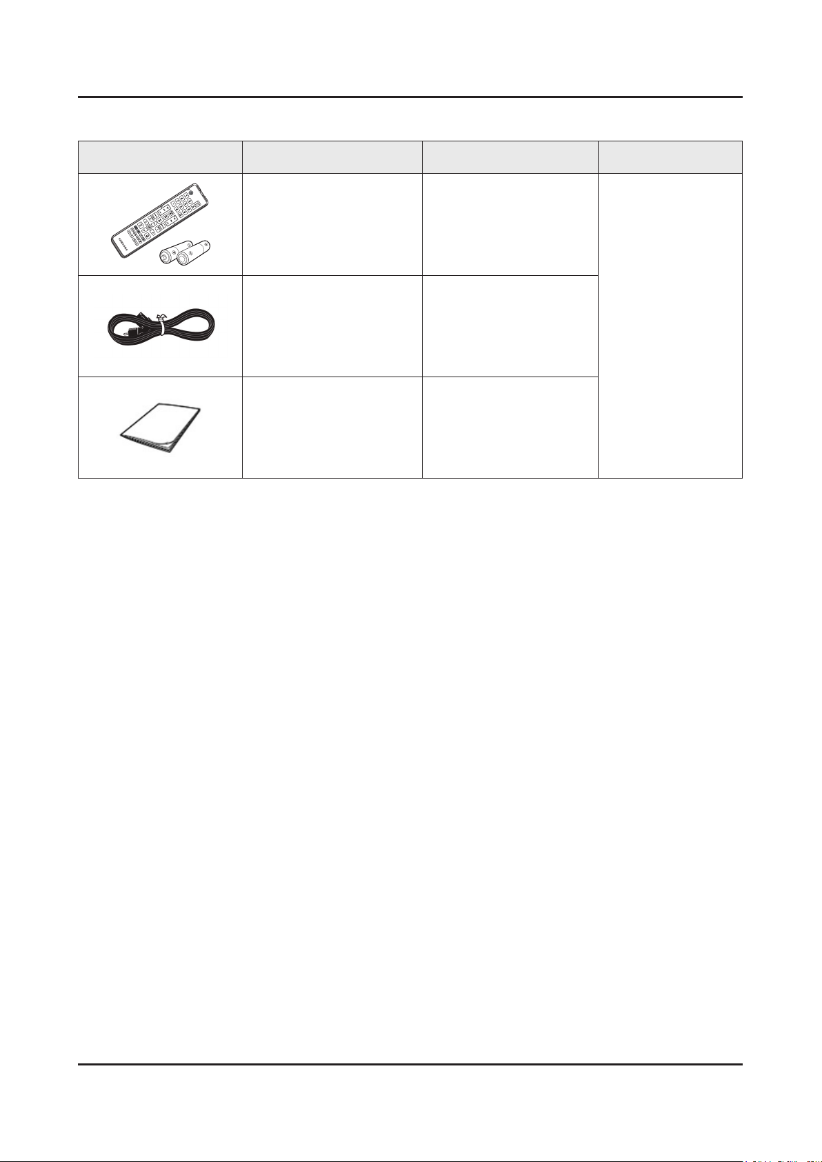
2-2. Accessories
Product Description Code. No Remark
Remote Control & Batteries
(AAA x 2)
Power Cord
Owners Manual
AA59-00790A (AU)
AA59-00793A (NZ,SG)
AA59-00797A (Etc.)
3903-000845 (AU,NZ)
3903-000847 (SG)
3903-000849 (Etc.)
BN68-04827A (AU)
BN68-04827F (NZ)
BN68-04827C (SG)
BN68-04827B (Etc.)
2-8
Page 17
3. Disassembly and Reassemble
3. Disassembly and Reassembly
This section of the service manual describes the disassembly and reassembly procedures for the LED TV.
This LED TV contains electrostatically sensitive devices. Use caution when handling these components.
WARNING
3-1. Disassembly and Reassembly
Disconnect the LED TV from the power source before disassembly.1.
Follow these directions carefully; never use metal instruments to pry apart the cabinet.2.
CAUTION
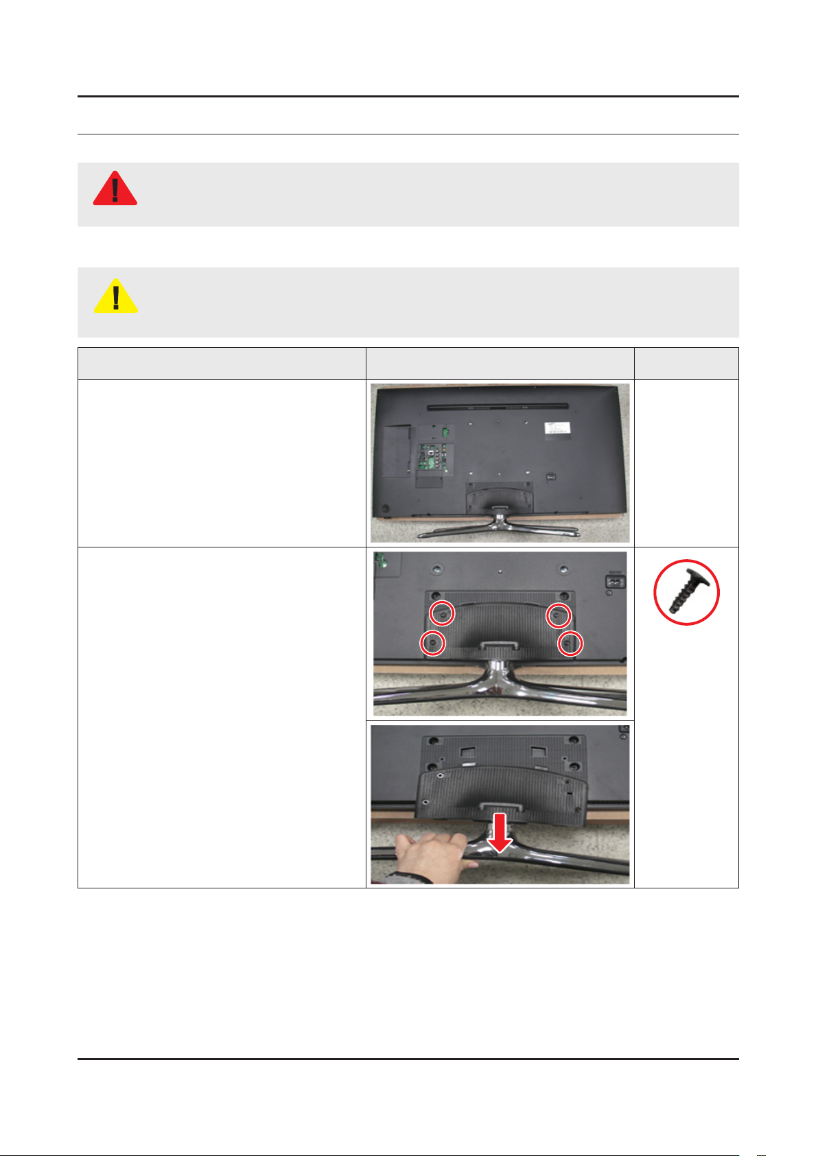
Place TV face down on cushioned table.
If there is no additional coment, it is same for all inches.3.
Description Picture Description Screws
1
Remove 4 screws from the Stand and
2
Remove Stand.
6003-001782
3-1
Page 18
3-2
3. Disassembly and Reassemble
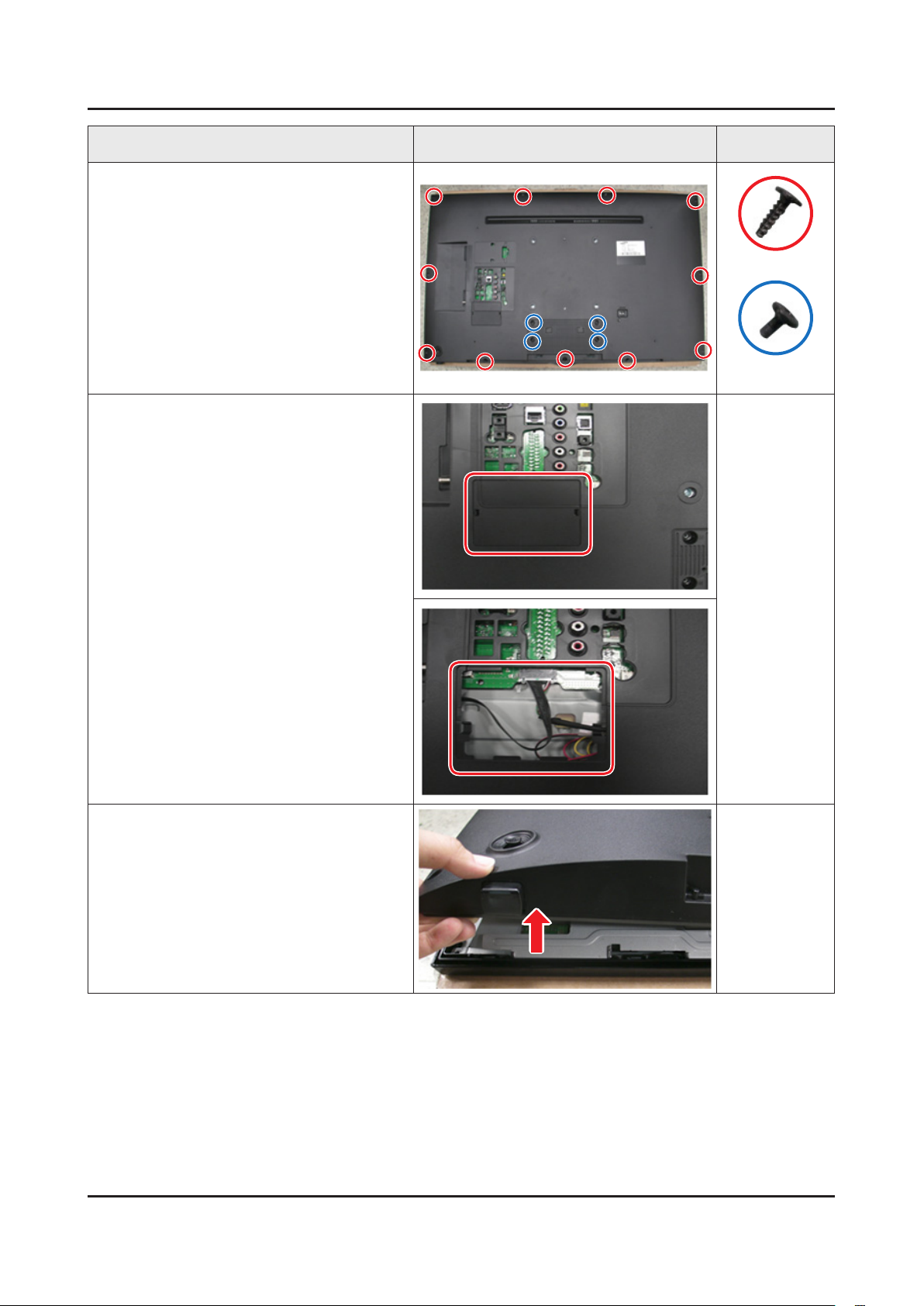
Description Picture Description Screws
Remove 15 screws of Rear Cover.
3
Remove the Cover Jack.
4
6003-001782
6003-002755
Lift up Rear Cover slightly from the bottom.
5
Page 19
3-3
3. Disassembly and Reassemble
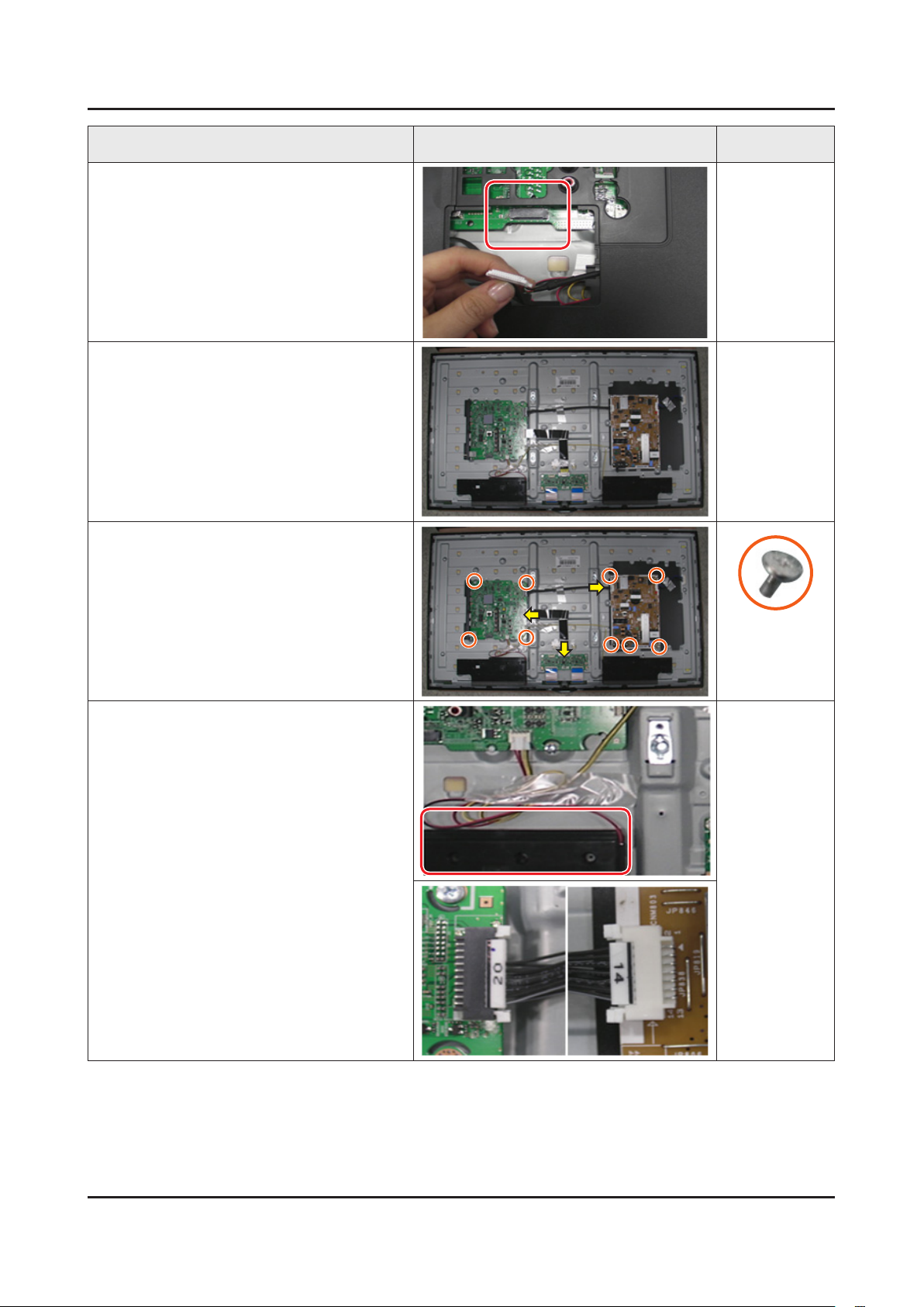
Description Picture Description Screws
Disconnect the Function Assy Cable.
6
Remove the Rear Cover.
7
Remove 9 screws of Main Board and
8
Power Board.
Remove the Speakers and Power Cables.
9
6001-003016
Page 20
3-4
3. Disassembly and Reassemble
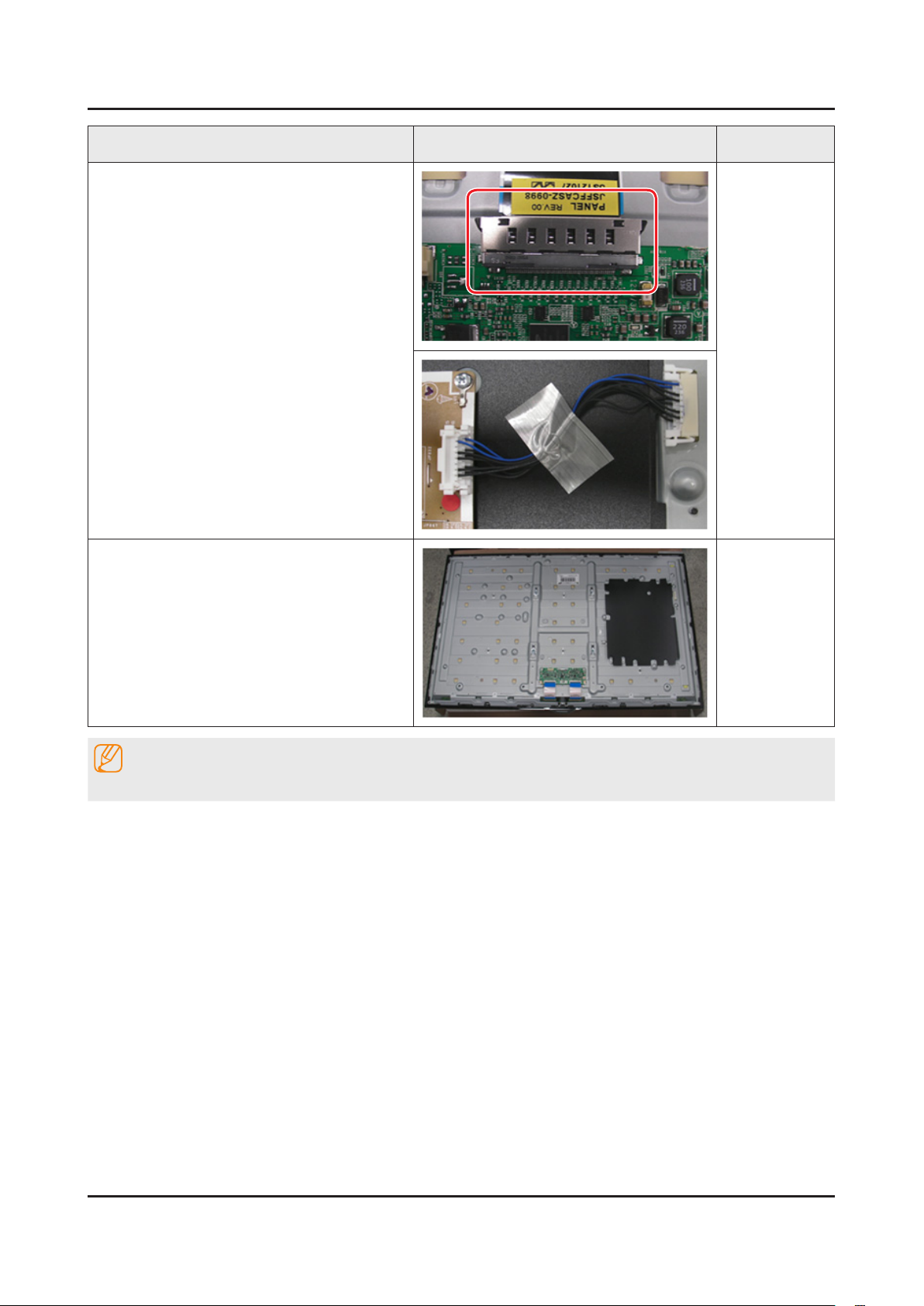
Description Picture Description Screws
Remove the LVDS Cable and Panel Drive
10
Cable.
Completed disassembly.
11
NOTE
Reassembly procedures are in the reverse order of disassembly procedures.
Page 21
3-5
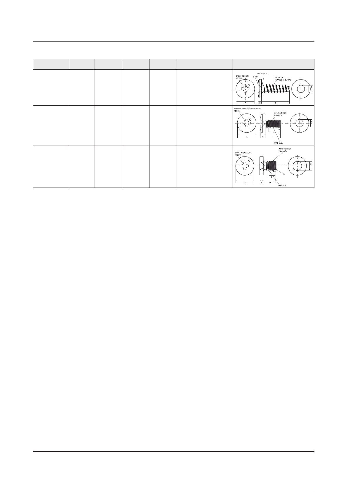
3. Disassembly and Reassemble
A
CROSS #2(3.56)
RECESS
B 8.0R
★ C 0.6 ± 0.1
M4.0 x 1.8
TAPPING △ B-TYPE
BD
C
A
CROSS #2(3.08 특수 Punch D:7.5
RECESS
M3 x 0.5 PITCH
SCALOCK
TRAP 도포
인치
BD
E
C
A
CROSS #2(★M3.0F)
RECESS
M3 x 0.5 PITCH
SCALOCK
B
B
D
C
TRAP 도포
인치
Screw Size
Code No. COLOR A (mm) B (mm) C (mm) Q'ty Screw Image
32" : 10EA,
6003-001782 BLACK 7.80~8.20 1.85~1.95 3.81~3.91
40" : 17EA,
46": 20EA,
50" : 20EA
6001-002755 BLACK 7.1~7.5 1.9~2.0 2.98~3.02
32" : 2EA,
40"/46"/50": 4EA
6001-003016 WHITE 5.6~6.0 1.15~1.25 2.92~2.98 9EA
Page 22
3-6
3. Disassembly and Reassemble
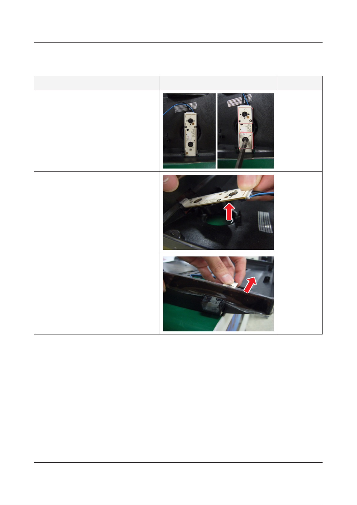
3-2. Assy Board P-Jog Switch & Ir
How to disassembly
Description Picture Description Refer
Loosen 2 screws.
1
Pull out a jog function.
2
Page 23
3-7
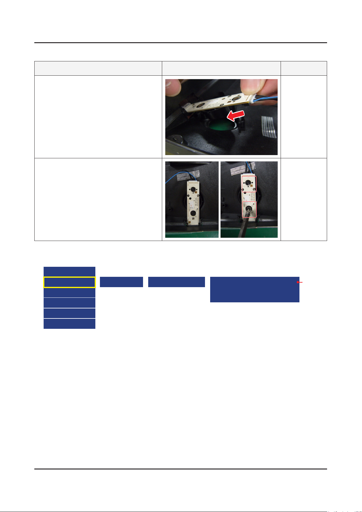
3. Disassembly and Reassemble
How to assembly
Insert a jog function.
1
Put 2 screws.
2
Description Picture Description Refer
When you want to ignore the funtion key actions
Option
Control
Debug
SVC
ADC/WB
Advanced
Cong Option Navigation Key Func
0 : New Function (Naviagtion) Key
1 : Old Function (Touch) Key
2 : Do not work Function key
[ Default ]
Page 24
3-8
3. Disassembly and Reassemble
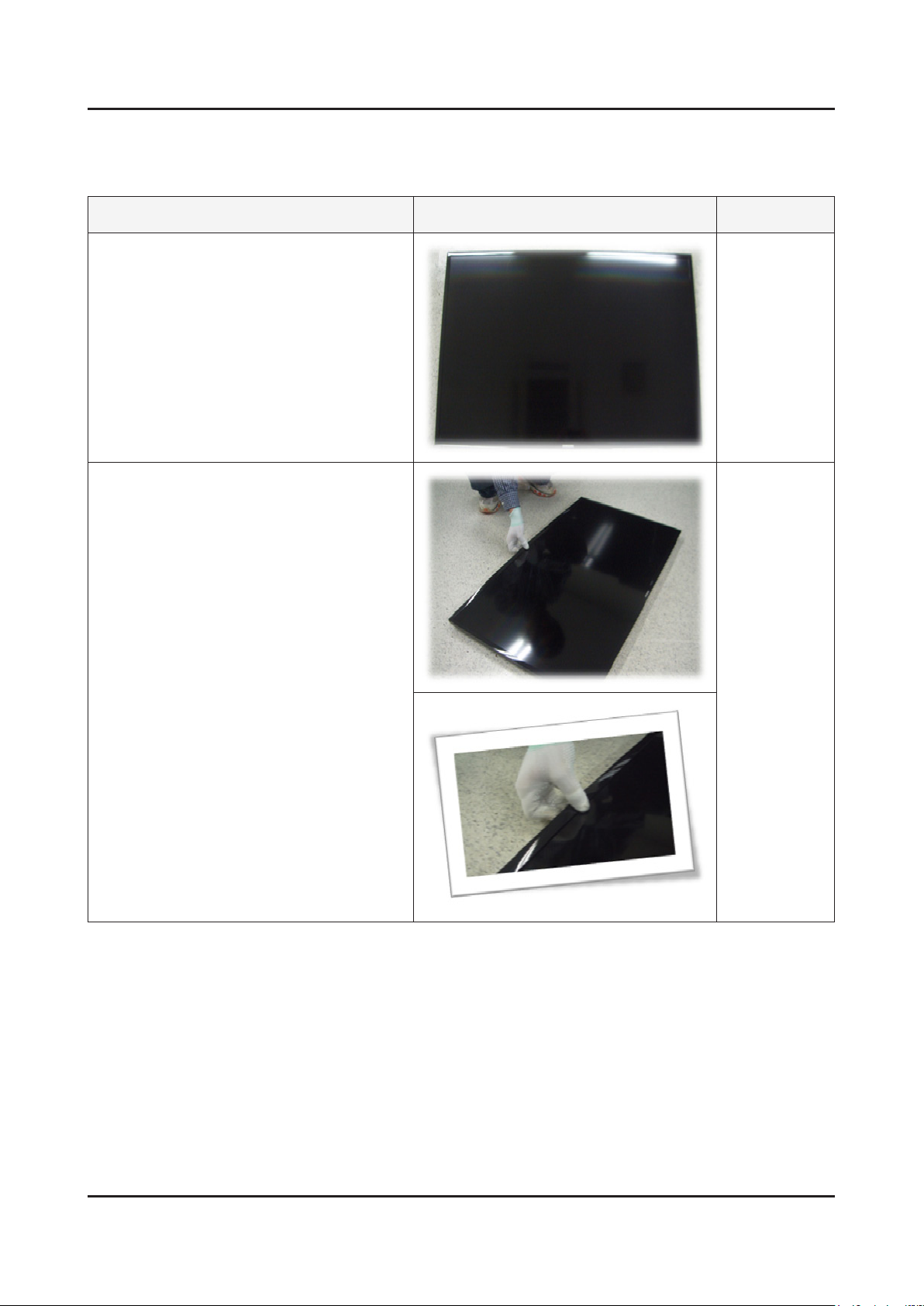
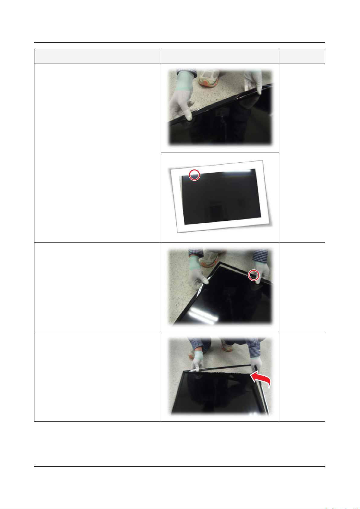
3-3. Disassembly(PTC)
How to disassembly
Description Picture Description Refer
Place TV face up on cushioned table.
1
Products at the top of the central TOP-
2
CHASSIS is rotated by 45 degrees outward
and pulls.
Page 25
3-9
3. Disassembly and Reassemble
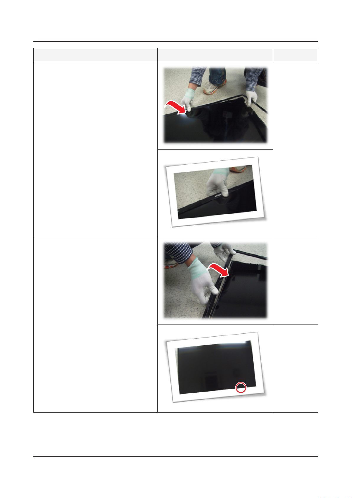
Description Picture Description Refer
Pull in the same way from the center of the
3
top.
Pull the left part of the product as shown
4
while holding the raised portion on gure 3.
Pull the bottom part of the product as
5
gure 2 while holding the raised portion on
gure 4.
Page 26
3-10
3. Disassembly and Reassemble
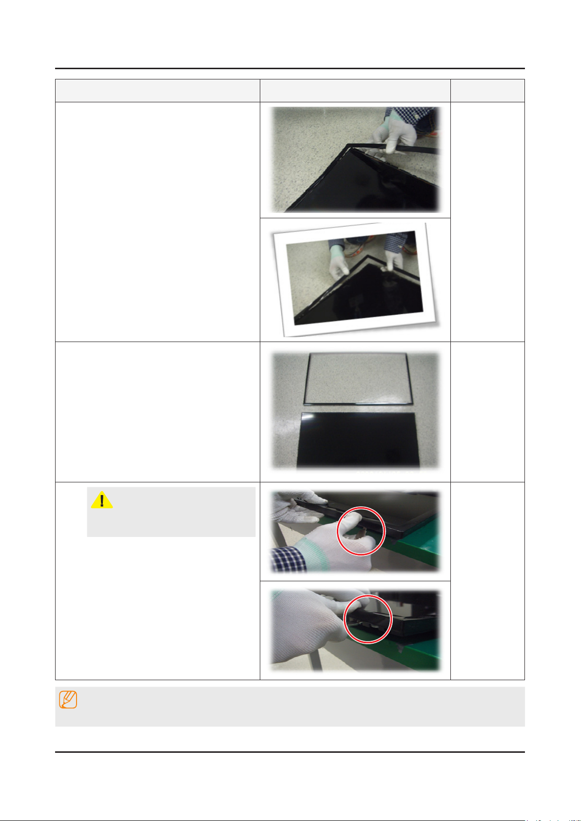
Description Picture Description Refer
As shown in the picture, Lift the bottom of
6
the TOP-CHASSIS.
Pull the products at the bottom of the right
7
side of the chassis.
Page 27
3-11
3. Disassembly and Reassemble
Description Picture Description Refer
Lift the bottom of the chassis with one
8
hand and holding the bottom of the product
after you pull the right side of the product
chassis.
Disassembly is complete.
9
CAUTION
To use JIG : Does not lift the chassis by
hand, JIG using the lift.
NOTE
Reassembly procedures are in the reverse order of disassembly procedures.
Page 28
4. Troubleshooting
4-1. Troubleshooting
Previous Check
Check the various cable connections rst.1.
Check to see if there is a burnt or damaged cable. -
Check to see if there is a disconnected or loose cable connection. -
Check to see if the cables are connected according to the connection diagram. -
Check the power input to the Main Board.2.
How to distinguish if the problem is caused by Main Board or T-Con Board.3.
No Video - : If the problem is No Video but BLU is on and Indication LED is blinking repeatedly and faster than
nomal booting, replace the T-Con Board.
Distorted Picture - : Check the inner patterns.
For All mode
X12 FOX_FT1 FRC Post Picture Problem
OK OK NG Main Board or Signal Source
NG OK NG Main Board
4. Troubleshooting
NG NG NG Main or LVDS cable or T-con or Panel
Only for HDMI mode (additional check)
HDMI Picture Problem
OK NG There is no problems after HDMI IC check HDMI source or HDMI jack.
NG NG There is no problems before HDMI IC check X10+ pattern or LVDS cable or T-con.
How to check inner pattern?
Factory mode. ((mute → 1 → 8 → 2 → Power on when TV is in ‘stand-by mode’)1.
Move to SVC menu.2.
Move to Test Pattern.3.
Check inner patterns.4.
4-1
Page 29
4-2
4. Troubleshooting
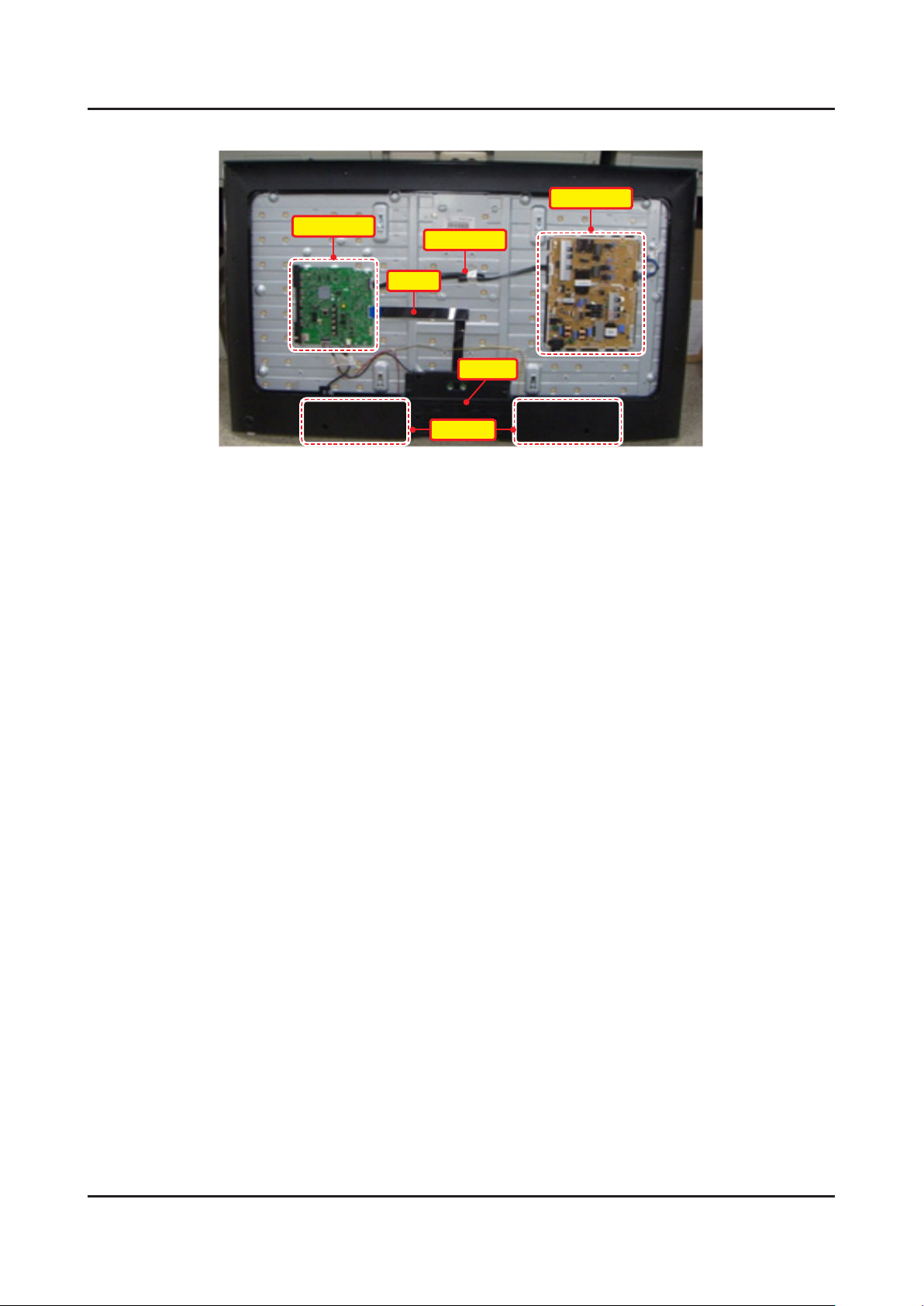
Inside View
Power Ass’y
Main Ass’y
20P Cable
LVDS
T-Con
Speaker
Page 30
4-2. How to Check Fault Symptom
4-3
4. Troubleshooting
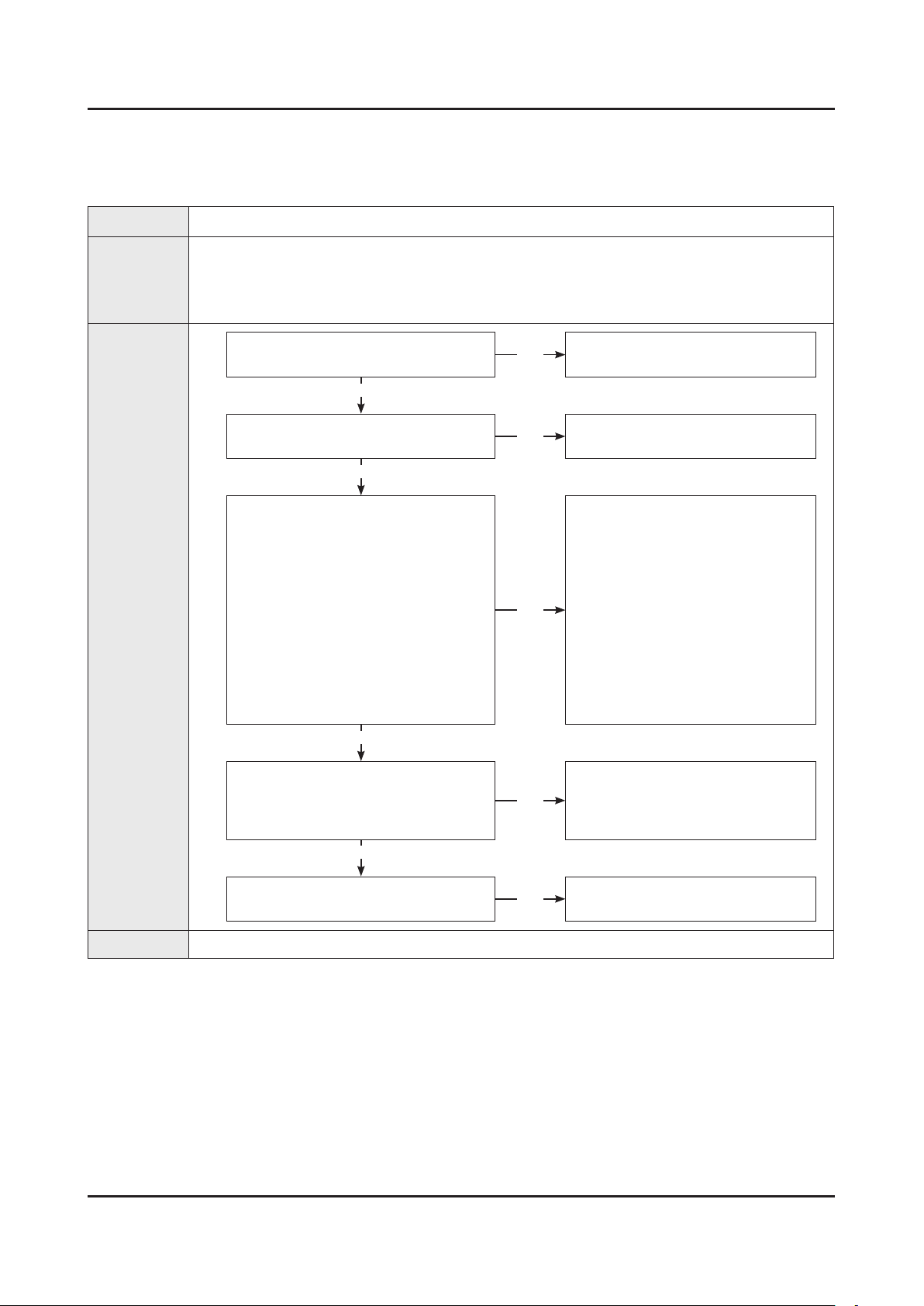
No Video (HDMI 1, 2, 3 - Digital Signal)
*Refer to the next page to check the lacation such a CN201 or IC201 SVC Manual mentioned.
Symptom
Major
checkpoints
Audio is normal but no picture is displayed on the screen.•
Check the HDMI source.•
Check the HDMI switch.•
This may happen when the LVDS cable connecting the Main Board and the Panel is •
disconnected.
Diagnostics
Power indicator LED is off.
Lamp(Backlight) on, no video ?
Yes
Check the HDMI source and
check the connection of HDMI cable ?
Yes
Check the signal at Input of Main board ?
HDMI1 Clk : Pin #10, #12 of CN602_H2
DATA : Pin #7, #9, #4, #6, #1, #3 of
CN602_H2
HDMI2 Clk : Pin #10, #12 of CN603_H3
DATA : Pin #7, #9, #4, #6, #1, #3 of
1
HDMI3 Clk : Pin #10, #12 of CN604_H4
DATA : Pin #7, #9, #4, #6, #1, #3 of
HDMI4 Clk : Pin #10, #12 of CN601_H1
DATA : Pin #7, #9, #4, #6, #1, #3 of
Check the LVDS clk signal at output of
2
TX2_CLK : ODD_TXCLK_DN/DP
TX4_CLK : EVEN_TXCLK_DN/DP
CN603_H3
CN604_H4
CN601_H1
Yes
Main board.(TX)
No
No
No
No
Check a set in the ‘Stand-by mode’.
Input the HDMI signal properly.
Check CN601~4.
Check HDMI cable.
Change the Main Ass’y
or
Check IC1001(X12).
Change the Main Ass’y.
Check IC1001(X12).
Change the Main Ass’y.
Yes
Check the LVDS cable?
Replace the T-con / LCD panel?
Caution Make sure to disconnect the power before working on the IP board.
No
Please, Contact Tech support.
Page 31

4-4
4. Troubleshooting
Location of Parts
Main Board_Front
B
A
Detail
CN604_H4 : HDMI3
CN603_H3 : HDMI2
A
CN602_H2 : HDMI1
CN601_H1 : HDMI4
B
Page 32

4-5
4. Troubleshooting
WAVEFORMS
1
2
HDMI input (RX_Data, RX_Clk)
LVDS output
Page 33

4-6
4. Troubleshooting
No Video (Tuner_CVBS)
*Refer to the next page to check the lacation such a CN201 or IC201 SVC Manual mentioned.
Symptom Audio is normal but no picture is displayed on the screen.•
Check the Tuner CVBS source.•
Major
checkpoints
Check the Tuner.•
This may happen when the LVDS cable connecting the Main Board and the Panel is •
disconnected.
Diagnostics
Power indicator LED is off.
Lamp(Backlight) on, no video ?
Yes
Check the RF source and check the
connection of RF cable ?
Yes
Check the Power of Tuner ?
1
2
3
Pin #4 of Tuner : B3.3V_Tuner
Pin #1 of Tuner : B1.8V_Tuner
Yes
Check the CVBS data out of IC1001 ?
C807 : Tuner CVBS
Yes
Check the LVDS clk signal at output of
Main board.(TX)
TX2_CLK : ODD_TXCLK_DN/DP
TX4_CLK : EVEN_TXCLK_DN/DP
Yes
No
No
No
No
No
Check a set in the ‘Stand-by mode’.
Input the RF source properly.
Change the Main Ass’y.
Check IC1001(X12).
Change the Main Ass’y.
Check IC1001(X12).
Change the Main Ass’y.
Check the LVDS cable?
Replace the T-con / LCD panel?
Caution Make sure to disconnect the power before working on the IP board.
No
Please, Contact Tech support.
Page 34

4-7
4. Troubleshooting
Location of Parts
Main Board_Front
B
C
A
Detail
A
Pin #4 : B3.3V
Pin #1 : B1.8V
B
C
Page 35

4-8
4. Troubleshooting
WAVEFORMS
1
2
CVBS OUT (Grey Bar)
LVDS output
Page 36

No Video (Tuner DTV)
4-9
4. Troubleshooting
*Refer to the next page to check the lacation such a CN201 or IC201 SVC Manual mentioned.
Symptom
Major
checkpoints
Audio is normal but no picture is displayed on the screen.•
Check the DTV source.•
Check the Tuner.•
This may happen when the LVDS cable connecting the Main Board and the Panel is •
disconnected.
Diagnostics
Power indicator LED is off.
Lamp(Backlight) on, no video ?
Yes
Check the RF source and check the
connection of RF cable ?
Yes
1
2
2
Check the ‘signal strength’ in Self
Diagnosis menu Strength is enough ?
Yes
Check the Power of Tuner ?
Pin #4 of Tuner : B3.3V_Tuner
Pin #1 of Tuner : B1.8V_Tuner
Yes
Check the LVDS clk signal at output of
Main board.(TX)
TX2_CLK : ODD_TXCLK_DN/DP
TX4_CLK : EVEN_TXCLK_DN/DP
Yes
No
No
No
No
No
Check a set in the ‘Stand-by mode’.
Input the RF source properly.
Check the D-TV source.
Change the Main Ass’y.
Check IC1001(X12)
Change the Main Ass’y.
Check the LVDS cable?
Replace the T-con / LCD panel?
Caution Make sure to disconnect the power before working on the IP board.
No
Please, Contact Tech support.
Page 37

4-10
4. Troubleshooting
Location of Parts
Main Board_Front
B
A
Detail
A
Pin #4 : B3.3V
Pin #1 : B1.8V
B
Page 38

4-11
4. Troubleshooting
WAVEFORMS
1
2
LVDS output
CH_CLK, CH_VALID
Page 39

4-12
4. Troubleshooting
No Video (Video AV)
*Refer to the next page to check the lacation such a CN201 or IC201 SVC Manual mentioned.
Symptom
Audio is normal but no picture is displayed on the screen.•
Major
checkpoints
Diagnostics
Caution Make sure to disconnect the power before working on the IP board.
Check the Video CVBS source•
This may happen when the LVDS cable connecting the Main Board and the Panel is •
disconnected.
Power indicator LED is off.
Lamp(Backlight) on, no video ?
Yes
Check the video source and
check the connection of video cable?
Yes
Check the LVDS clk signal at output of
2
TX2_CLK : ODD_TXCLK_DN/DP
TX4_CLK : EVEN_TXCLK_DN/DP
Main board.(TX)
Yes
Check the LVDS cable?
Replace the T-con / LCD panel?
No
No
No
No
Check a set in the ‘Stand-by mode’.
Input the video source properly.
Check IC1001(X12).
Change the Main Ass’y.
Please, Contact Tech support.
Page 40

4-13
4. Troubleshooting
Location of Parts
Main Board_Front
A
B
Detail
A
R816 : COMP2_Y_CVBS
B
Page 41

4-14
4. Troubleshooting
WAVEFORMS
1
2
CVBS OUT (Grey Bar)
LVDS output
Page 42

No Video (Component)
4-15
4. Troubleshooting
*Refer to the next page to check the lacation such a CN201 or IC201 SVC Manual mentioned.
Symptom
Audio is normal but no picture is displayed on the screen.•
Major
checkpoints
Diagnostics
Check the Component source.•
This may happen when the LVDS cable connecting the Main Board and the Panel is •
disconnected.
Power indicator LED is off.
Lamp(Backlight) on, no video ?
Yes
Check the component source and
check the connection of component
cables(Y,Pb,Pr) ?
Yes
Does the component data appear at ?
1
2
COMP2_Y_CVBS : R816
Pb : R817
Pr : R815
Yes
Check the LVDS clk signal at output of
Main board.(TX)
TX2_CLK : ODD_TXCLK_DN/DP
TX4_CLK : EVEN_TXCLK_DN/DP
Yes
No
No
No
No
Check a set in the ‘Stand-by mode’.
Input the component source properly.
Check CN502.
Change the Main Assy
Check IC1001(X12).
Change the Main Ass’y.
Check the LVDS cable?
Replace the T-con / LCD panel?
Caution Make sure to disconnect the power before working on the IP board.
No
Please, Contact Tech support.
Page 43

4-16
4. Troubleshooting
Location of Parts
Main Board_Front
A
B
Detail
R817 : COMP2_PB
A
R816 : COMP2_Y_CVBS
R815 : COMP2_PR
B
Page 44

4-17
4. Troubleshooting
WAVEFORMS
1
2
Compnent_Y (Gray scale) / Pb / Pr (Color bar)
LVDS output
Page 45

4-18
4. Troubleshooting
No Sound (1.Speaker 2.Monitor_out, 3.Optical)_X12
*Refer to the next page to check the lacation such a CN201 or IC201 SVC Manual mentioned.
Symptom
Video is normal but there is no sound.•
Major
checkpoints
Diagnostics
When the speaker connectors are disconnected or damaged.•
When the sound processing part of the Main Board is not functioning.•
Speaker defect.•
Check the source and check the
connection of sound cable (Comp) ?
Yes
Check the signal at input of Main board?
AV, COMP L/R : RA503
Yes
Check the DATA between the Audio IC’s ?
1
2. Check the Monitor out sound data at
2
Pin #15 of IC301 : Bclk
Pin #20 of IC301 : LRclk
Pin #23,#24 of IC301 : I2C_SDA/SCL
Yes
1. Check the Speaker sound data at
CN302
CN303_IBR
3. Does the SODIF OUT sound data
appear at ? OP301
No
No
No
No
Input the sound source properly.
Check CN502.
Change the Main Assy.
Check IC301.
Change the Main Assy.
Check IC301.
Change the Main Assy.
Yes
Replace speaker ?
Caution Make sure to disconnect the power before working on the IP board.
No
Please, Contact Tech support.
Page 46

4-19
4. Troubleshooting
Location of Parts
Main Board_Front
C
A
B
Detail
Pin #20 : LRclk
RA503 : COMP_L/R
A
B
Pin #23,#24 : I2C_SDA/SCL
Pin #15 : Bclk
C
CN303_IBR: Monitor out_Sound
OP301: Optical
CN302 : SPK
Page 47

4-20
4. Troubleshooting
WAVEFORMS
1
2
MCLK / LRCLK / PCM_I2C_DATA
Speaker / Monitor OUT , SPDIF OUT
Page 48

4-21
4. Troubleshooting
4-3. Factory Mode Adjustments
4-3-1. Detail Factory Option
NOTE
If you replace the main board with new one, please change the factory option as well.
The options you must change are "Type".
5500_5300
Model Name UA32F5*00 UA40F5*00 UA46F5*00
Vendor
Panel
SMPS PD Board BN44-00605A BN44-00645A BN44-00611A
MAIN ASSY
(depend on country)
Byte Item
0 Factory Reset - - -
1 Type
2 Local Set AD_AU_NZ2
3 SW Model F5500
4 BOM Model 5500
Code
Spec.
Chassis
Ass'y
PBA Ass'y
code
AUO
LCM
BN07-01259A
BN95-01109A
HF320BGA-B1
HF320BGS-V1
BN91-10540Y BN91-10540Z BN91-10596A
BN94-06295Y BN94-06295Z BN94-06309D
32R6AF0S
32H6AF0S
SDC
SHARP
BN95-00887A
BN95-00909A
LSF400HM02
LK400D3HB7K
40A6AF0S
40H6AF0S
BN95-00891A
LSF460HN02
SDC
46A6AF0S
5 Tuner SI_ADI
6 Ch table NONE
7 Country
8 Front Color
-
U-S-C-5K
Page 49

4-22
4. Troubleshooting
5500, 5300, 4500
Model Name UA50F5*00 UA32F4500
Vendor
Panel
SMPS PD Board BN44-00612A BN44-00604B
MAIN ASSY
(depend on country)
Byte Item
0 Factory Reset - -
1 Type
2 Local Set AD_AU_NZ2
3 SW Model F5500 F4500
4 BOM Model
5 Tuner SI_ADI
6 Ch table NONE NONE
7 Country -
Code
Spec.
Chassis Ass'y BN91-10323X BN91-10318F
PBA Ass'y code BN94-06364A BN94-06174F
AUO
AUO
BN07-01278A
BN07-01278B
HF500BGA-B1
HF500BGA-B2
50R6AF0S
50R6AF0S
5500 4500
HF320AGM-C1
CMI
BN07-01263A
32P6AH0S
8 Front Color U-S-C-5K NONE
Page 50

4-3-2. Entering Factory Mode
4-23
4. Troubleshooting
To enter ‘Service Mode’ Press the remote -control keys in this sequence :
If you do not have Factory remote control•
Power OFF Info MENU MUTE Power On
If you have Factory remote control•
INFO Factory
If you don’t have Factory remote control, can’t control some menus•
Initial SERVICE MODE DISPLAY State
Option
Control
Debug
SVC
ADC/WB
Advanced
T-MST12UABC-xxxx
T-MST12DEUS-xxxx
BT Version : xxxx
Camera Version : xxxx
E-Manual : xxxx
EDID SUCCESS
CALIB : AV/COMP/PC/HDMI/
Option : 40H6AF0S,AD_AU_NZ2,5500,NONE
USB RS232C : OFF
SDAL-X12-MAIN-xxxx-xxxx
RFS : "X12 0071" KER/201x-xx-xx
KERNEL : 8.0837, D / Onboot :xxxx.x
Backend IC[x], Data Ver : xxxx
TCON Version : xxxx
DTP-DTVTD-xxxx
Model : UA40F5500
Wired MAC SUCCESS
Wireless MAC SUCCESS
DRM : Crt O, Nf O, Wv O, Hc O, Dc O, Mx O, MI O
Factory Data Ver : 97
EERC Version : 51
DTP-BP-HAL-3183
DTP-AP-CNC-3151
DTP-AP-MM-3145
DTP-AP-WP-3148
DTP-BP-MW-3156
DTP-BP-APP-3156
POP-FLA-13-TEMP
Date of purchase : mm/dd/yyyy
Page 51

4-24
4. Troubleshooting
4-3-3. Factory Data
Note
Version of the software is written in 0002.•
Black• : I should not be possible to adjust or change that does not require a change item
Blue : Adjustment Services for the corresponding
Red : Items that are secured
Option
Factory Menu
Data Range Remark Key
Name
Factory Reset -
Type 40H6AF0S 32P6AH0S (UF4500)
32R6AF0S/40H6AF0S/46A6AF0S/50R
6AF0S(UF5500)
Local Set AD_AU_NZ2 EU/EU_GER (depended on buyer
SW Model UF5500
BOM Model 5500
TUNER SI_ADI
Ch Table NONE
code)
UF5500/UF4500
5500/4500
Do not change
MRT Option
Front Color U-S-C-5K
LVDS FORMAT JEIDA
Language_Arabic US
Region USA
PnP Language ENG_US
WIFI REGION S
NONE/U-S-C-5K
OTN Support ON
OTA Support OFF
TTX OFF
China HD OFF
NT Conversion OFF
Num of DTV 1
Num of AV 1
Num of COMP 1
Num of HDMI 4
Num of SCART 0
Num of USB Port 3
Num of HeadPhone 0
Num of RVU 1
Page 52

4-25
4. Troubleshooting
Factory Menu
Data Range Remark Key
Name
Num of Display 2
Num of IPTV 0
Num of RUI 0
Num of PVR
RECORD
TOOLS Support 40
LNA Support OFF
24Px4 Support OFF
BD Wise Support ON
Data Service
Support
PVR Support OFF
CI Support OFF
LEDMotionPlus
Support
Natural Mode
Support
0
OFF
ON
ON
Relax Mode Support OFF
HDMI/DVI SEL 4
Select LCD/PDP LCD
Wall Mount OFF
HV Flip
Light Effect OFF
e-Pop Default 1
CAMERA Support OFF
NETWORK Support 3
EcoSensor Support ON
3D Support ON
BT Support ON
BT ADDRESS
Engineer Option
Auto Power MEMORY
Type Of PANEL KEY None
5 Way Function Key R BACK
HV Flip / H Filp / OFF
Contents Bar OFF
Cable Modulation QAM
Standby led on/off OFF
Recognition Support
IF AGC 0
Page 53

4-26
4. Troubleshooting
Factory Menu
Data Range Remark Key
Name
D AGC 0
PH BW 0
FQ BW 0
PH RATE 0
PD EN 0
PEQ Inx 0
WF Scale
WF Type 0
Nu of Network
Stream
DP V Size 0
Backend Device FOX-FT1
BT_AUDIO_ON_
OFF
Cong_AV_PATH
ECO Standby OFF
1
OFF
Fast Logo Delay 0
Num of PANEL KEY 6
Control
Factory Menu Name Data Range Remark Key
EDID
EDID ON/OFF OFF
EDID WRITE ALL …
EDID WRITE HDMI …
EDID Ver … HDMI 1.3/HDMI1.2
EDID Port
Sub Option
RS-232 Jack UART Debug/UART
Watchdog OFF
Checksum 0x0000
Fast Boot in Production OFF
USB Serial OFF
Eeprom Reset
ECO IC TYPE NONE
Info Link Server Type development
Info Link Country None
Page 54

4-27
4. Troubleshooting
Factory Menu Name Data Range Remark Key
TTX Group -
Visual Test -
MediaPlayDB -
OPTION_SWU
OTN Server Type operating
OTN Test Server OFF
SWU Reset
SWU Duration OFF
SWU Fail Test OFF
OPTION_NUM
Num of ATV 1
Num of SVIDEO 0
Num of PC 0
Num of DVI 0
Num of OPTICAL Link 1
Num of MEDIA 1
Num of Tuner 1
Num of ISP 1
RF Remocon Support OFF
CDD mode -
DPMS Support OFF
Num of IPTV CIP 0
Num of CI 0
Num of DECODER 0
T-CON Device
BOARD CONTROL OFF
HP LINE LineOut
RM
Server Type Operating
RTS Mode OFF
PSA
FKP Download1 0
FKP Download2 0
LMK threshold 3
Low threshold 10
High threshold 15
CSB ON
Page 55

4-28
4. Troubleshooting
Factory Menu Name Data Range Remark Key
CLB ON
PDP Option
Pixel Shift Test OFF
Logic SW 0
Panel Temperature 0
LOGIC Waveform Day 0
Logic CheckSum 0
MRT 0
SAPC Timer
APC Speed
Hotel Option
Hospitality Mode OFF
Power On …
Menu OSD …
Operation …
Music Mode …
External Source …
Eco Solution …
Cloning …
Shop Option
Shop Mode OFF
Exhibition Mode OFF
3D Cube OFF
Asia Option
Unbalance OFF
AF Level adjust 3
TX Power Level 0
Mono Last Memory OFF
H Shaking OFF
Sound
Carrier_Mute OFF
High Devi OFF
Speaker Delay Normal 0x6Eh
SPDIF PCM Gain -9dB
FM M Prescale 0x30h
FM Prescale 0x00h
AM Prescale 0x32h
Page 56

4-29
4. Troubleshooting
Factory Menu Name Data Range Remark Key
NICAM Prescale 0x48h
BTSC Mono Prescale 0x19h
BTSC stereo Prescale 0x2Fh
BTSC SAP Prescale 0x2Bh
A2Ident High THID 31
A2Ident Low THID 0
Pilot Level High Thld 0x28h
Pilot Level Low Thld 0x10h
Carrier2 Amp High THID 4
Carrier2 Amp Low THID 3
Carrier2 SNR High THR 16
Carrier2 SNR Low THR 80
Sig Error On 35
Sig Error Off 41
Amp Model TAS5745
Amp Volume 0xcbh
Amp Scale 0x35h
Amp Check Sum 0x000821B2
Woofer Type 0
Woofer Scale 0
Woofer Check Sum 0x8ah
Woofer Local EQ Checksum 0
Speaker EQ ON
PEQ Test Ready
Local Speaker EQ 0
Local EQ Checksum 0
Speaker cut-off Ferq 4
Audio-IP Test
SRS Tuning Parm 0
TruBass-CheckSum 0
Mic Scale 0
Subwoofer Support 0
India Sound OFF
AudioDock BT delay 50
Wall Filter Type 0
Wiselink Delay Menu 90
Page 57

4-30
4. Troubleshooting
Debug
Factory Menu Name Data Range Remark Key
Spread Spectrum
LVDS Spread ON
DDR Spread 1.0% Spectrum
Period 30K
Amplitude 1
HD SSC ON/Off ON
HD SSC Value 1
LVDS SSC ON/Off ON
LVDS SSC Value 0
DDR SSC ON/Off ON
DDR SSC Value 1
FRC LVDS SSC ON/OFF ON
FRC LVDS SSC MRR 10
FRC LVDS SSC MFR 1
FRC LVDS SSC Period 1
FRC LVDS SSC Modulation 1
FRC DDR SSC ON/OFF ON
FRC DDR SSC MRR 15
FRC DDR SSC MFR 1
FRC DDR SSC Period 1
FRC DDR SSC Modulation 1
DDR Margin
A CTRL_OFFSET_0_3 0x0
A CTRL_OFFSET_D 0x0
B CTRL_OFFSET_0_3 0x0
B CTRL_OFFSET_D 0x0
ND ADJ Support OFF
MICOM POWER OFF OFF
RF Mute Time 6ms
CI+1.3 OFF
FRC
FRC FDISPLAY ON/OFF 0
3D FDISPLAY ON/OFF OFF
PC Mode ON/OFF OFF
Tuner Margin 10
MPEG Margin 1000
Page 58

4-31
4. Troubleshooting
Factory Menu Name Data Range Remark Key
H.264 Margin 8
CAM Wait Time
TS Clock deldy 0
TCON_TEMP READ 0
TEMP LAST 60
DCC VERSION 0x0
DCC CHK SEL 0
DCC CHECK LOCAL 0x0
DCC CHECK TOTAL 0x0
MulitACC Checksum 0
IIC Bus stop OFF
Tuner Status
DVB
SNR
BER
Signal Strength
Bandwidth
Frequency
LNA Status
FFT
Modulation
Code Rate
GI
Hier Modulation
Frequency offset
Timing offset
AGC
UCB
PLL Type
DEMOD Type
TPS Lock
RS Lock
SSI
SQI
Firmware Version
ISDB-T
FFT Size_1
Page 59

4-32
4. Troubleshooting
Factory Menu Name Data Range Remark Key
Guard Interval_1
Freq. Offset_1
SNR_1
IF AGC_1
TMCC Lock_1
TS Packer_1
Master Lock_1
A_Modulation_1
A_Code Rate_1
A_Timer InterLeave_1
A_Segments Num_1
A_BER_1
B_Modulation_1
B_Code Rate_1
B_Timer InterLeave_1
B_Segments Num_1
B_BER_1
C_Modulation_1
C_Code Rate_1
C_Timer InterLeave_1
C_Segments Num_1
C_BER_1
SVC
Factory Menu Name Data Range Remark Key
Test Pattern
Pattern Sel OFF
Logic Pattern Sel …
Logic Level Sel …
FRC Pre Test Pattern 0
FRC Post Test Pattern 0
FRC3D Fdisplay OFF
FRC3D PC Mode OFF
SOC TCON Test Pattern 0
SOC TCON Pattern
Level
SOC TCON FRC Pattern 0
255
Page 60

4-33
4. Troubleshooting
Factory Menu Name Data Range Remark Key
HDMI WB Pattern OFF
HDMI Pattern Sel 0
Parma Pre Test Pattern 0
Parma Post Test Pattern 0
Panel Display Time 0Hr
SVC Info 0
Delete S/N 0
Upgrade
T-CON Usb Download Failute
T-CON CheckSum Error
Logic Usb D/L …
SUBMICOM UPGRADE Failute
BT UPGRADE
BT FREEPAIRING ON
Function Upgrade Failute
FRC3D FW Upgrade
Camera Upgrade
Mic Upgrade
CPLD USB Download
JP MICOM UPGRADE Failute
DP MICOM UPGRADE Failute
Jump Upgrade Failute
Smart Hub Reset 0
ER Count
WD Count 0
AR Count 0
WIFI ER Count
BT ER Count
HDMI Err Cnt
0
0
0
Camera ER Count 0
LOG(View Log)
Select Log Type NVRAM
Log View 0
Delete Log
Debug Log Down
Emergency Log Copy
Page 61

4-34
4. Troubleshooting
Factory Menu Name Data Range Remark Key
Self Diagnosis
Loop Back
LAN Test
AV Audio Test
DVIN Audio Test
CVBS Test
COMP Test
USB HUB Test
HDMI Test
SCART Audio Test
SCART CVBS Test
SCART RGB Test
CPU
DDR
FLASH
EEPROM
Sound AMP
HDMI Switch IC
USB HUB IC
WIFI
LVDS
T-CON/FRC
PCB Test
MOIP
App Self Test
Device self Test
Voltage
EcoSensor
BT
EXT Sound Inspection
Woofer Sound Inspection NONE
ATV CH Inspection
DTV CH Inspection
Satellite CH Inspection
IPERF
OPTION HDMI
Expert
Stopped
Page 62

4-35
4. Troubleshooting
Factory Menu Name Data Range Remark Key
DVB CI
CAL Data Backup
CAL Data Restore
…
…
ADC/WB
Factory Menu Name Data Range Remark Key
ADC
AV Calibration Success
Comp Calibration Success
PC Calibration Success
HDMI Calibration Success
ADC Result
1st_Y_GH 258
1st_Y_GL 128
1st_Cb_BH …
1st_Cb_BL …
1st_Cr_RH …
1st_Cr_RL …
2nd_R_L 132
2nd_G_L 132
2nd_B_L 132
2nd_R_H 70
2nd_G_H 70
2nd_B_H 70
White Balance
R-Offset 128
G-Offset 128
B-Offset 128
R-Gain 128
G-Gain 128
B-Gain 128
WB_W2_R_Offset 128
WB_W2_B_Offset 128
WB_W2_R_Gain 164
WB_W2_B_Gain 63
WB_N_R_Offset 128
WB_N_B_Offset 128
Page 63

4-36
4. Troubleshooting
Factory Menu Name Data Range Remark Key
WB_N_R_Gain 151
WB_N_B_Gain 108
MGA
MGA On/Off OFF
R1_Gain …
B1_Gain …
G1_Gain …
R2_Gain …
B2_Gain …
G2_Gain …
R3_Gain …
B3_Gain …
G3_Gain …
R4_Gain …
B4_Gain …
G4_Gain …
R5_Gain …
B5_Gain …
G5_Gain …
R6_Gain …
B6_Gain …
G6_Gain …
R7_Gain …
B7_Gain …
G7_Gain …
R8_Gain …
B8_Gain …
G8_Gain …
R9_Gain …
B9_Gain …
G9_Gain …
R10_Gain …
B10_Gain …
G10_Gain …
Page 64

4-4. White Balance
4-37
4. Troubleshooting
4-4-1. Calibration
Into the Factory Mode.1.
Select 2. SVC Menu.
Select 3. ADC/WB menu.
Select 4. ADC menu.
Option
Control
Debug
SVC
ADC/WB
Advanced
4-4-2. Service Adjustment
ADC
AV Calibration
Comp Calibration
PC Calibration
HDMI Calibration
You must perform Calibration in the Lattice Pattern before adjusting the White Balance.
Color Calibration
Adjust Specication•
Source Setting Mode Pattern Use Equipment
HDMI 1280 x 720@60 Hz Pattern #24 (Chess Pattern) CA210 & Master MSPG925 Generator
(Chess Pattern)
Use other equipment only after comparing the result with that of the Master equipment. -
Input mode Calibration Pattern
CVBS IN (Model_#1) Perform in NTSC B&W Pattern #24 Lattice
Component IN (Model_#6) Perform in 720p B&W Pattern #24 Lattice
PC Analog IN (Model_#21) Perform in VESA XGA (1024x768) B&W Pattern #24 Lattice
HDMI IN Perform in 720p B&W Pattern #24 Lattice
Page 65

4-38
4. Troubleshooting
Method of Color Calibration (AV)
Apply the NTSC Lattice (N0. 3) pattern signal to the AV IN 1 port.1.
Press the Source key to switch to “AV1” mode.2.
Enter Service mode.3.
Select the “ADC” menu.4.
Select the “AV Calibration” menu.5.
In “AV Calibration Off” status, press the “► ” key to perform Calibration.6.
When Calibration is complete, it returns to the high-level menu.7.
You can see the change of the “AV Calibration” status from Failure to Success. 8.
Method of Color Calibration (Component)
Apply the 720p Lattice (N0. 6) pattern signal to the Component IN 1 port.1.
Press the Source key to switch to “Component1” mode.2.
Enter Service mode.3.
Select the “ADC” menu.4.
Select the “Comp Calibration” menu.5.
In “Comp Calibration Off” status, press the “ ►” key to perform Calibration.6.
When Calibration is complete, it returns to the high-level menu.7.
You can see the change of the “Comp Calibration” status from Failure to Success.8.
Method of Color Calibration (HDMI)
Apply the 720p Lattice (N0. 6) pattern signal to the HDMI1/DVI IN port.1.
Press the Source key to switch to “HDMI1” mode.2.
Enter Service mode.3.
Select the “ADC” menu.4.
Select the “HDMI Calibration” menu.5.
In “HDMI Calibration Off” status, press the “►” key to perform Calibration.6.
When Calibration is complete, it returns to the high-level menu.7.
You can see the change of the “HDMI Calibration” status from Failure to Success.8.
Page 66

4-4-3. Adjustment
4-39
4. Troubleshooting
Into the Factory Mode.1.
Select 2. SVC Menu.
Select 3. ADC/WB menu.
Select 4. White Balance menu.
Option
Control
Debug
SVC
ADC/WB
Advanced
White Balance
(low light)
Sub Bright
R offset
G offset
B offset
(hight light)
Sub Contrast
R gain
G gain
B gain
Page 67

4-40
4. Troubleshooting
4-5. White Ratio (Balance) Adjustment
You can adjust the white ratio in factory mode (1:Calibration, 3:White-Balance).1.
Since the adjustment value and the data value vary depending on the input source, you have to adjust these in CVBS, 2.
Component 1 and HDMI 1 modes.
The optimal values for each mode are congured by default. It varies with Panel’s size and Specication.3.
Equipment : CS-210•
Pattern: MIK K-7256 #92 “Flat W/B Pattern" as standard•
Altenate Equipmet : CA200& anyone Master supported •
pattern#92(refer to right photo)
Use other Equipment only after comparing the result •
with that of the Master equipment.
Set Aging time : 60 min•
Calibration and Manual setting for WB adjustment
HDMI : Calibration at #24 Chessboard Pattern Manual adjustment at #92 pattern (720p)•
COMP: Calibration at #24 Chessboard Pattern Manual adjustment at #92 pattern (720p)•
CVBS: Calibration at #24 Chessboard Pattern Manual adjustment at #92 pattern (NTSC)•
Note
If nishing in HDMI mode, adjustment coordinate is almost same in AV/COMP mode.
White Balance Manual adjustment
Type
LED_LOW
RGB Measurement
Levels
10 IRE 0x01 O
20 IRE 0x02 O
30 IRE 0x03 X
40 IRE 0x04 O
50 IRE 0x05 X
60 IRE 0x06 X
70 IRE 0x07 O
80 IRE 0x08 X
90 IRE 0x09 X
100 IRE 0x0A O
Code Check
Levels
10 IRE O 0.020 0.020 0.35
20 IRE O 0.020 0.020 0.35
30 IRE O 0.020 0.020 0.35
40 IRE O 0.020 0.020 0.35
50 IRE O 0.020 0.020 0.35
60 IRE O 0.020 0.020 NA
70 IRE O 0.020 0.020 NA
80 IRE O 0.020 0.020 NA
90 IRE O 0.020 0.020 NA
100 IRE O NA NA NA
Panel Inspection Spec.
Check x(±) y(±) Gamma(±)
Page 68

4-41
4. Troubleshooting
Gray Check Adjust Spec(xyL) 2nd Adjust Spec(xyL)
Levels
10 IRE 0x01 X 0.007 0.007 0.11 0.007 0.007 0.11
20 IRE 0x02 O 0.007 0.007 0.08 0.007 0.007 0.08
30 IRE 0x03 X 0.007 0.007 0.06 0.007 0.007 0.06
40 IRE 0x04 O 0.005 0.005 0.05 0.005 0.005 0.05
50 IRE 0x05 X 0.005 0.005 0.04 0.005 0.005 0.04
60 IRE 0x06 X 0.005 0.005 0.03 0.005 0.005 0.03
70 IRE 0x07 O 0.004 0.004 0.02 0.004 0.004 0.02
80 IRE 0x08 X 0.004 0.004 0.01 0.004 0.004 0.01
90 IRE 0x09 X 0.004 0.004 0.01 0.004 0.004 0.01
100 IRE 0x0A X NA NA NA NA NA NA
Code Check x(±) y(±) L(±) x(±) y(±) L(±)
Target Gamma 2.30
Black
Target xy
x y
0.231 0.208
Option x
Auto 0.282
Contrast
300000
0.299
Color Tone Target Spec.
High x y
COOL
0.274 0.286
x(±) y(±)
0.004 0.004NORMAL 0.293 0.307
WARM2
Low x y x(±) y(±)
COOL NA NA
WARM2 NA NA
0.328 0.353
NA NANORMAL NA NA
Panel Spec. ±
Gamma 2.2 0.30
x
y
y 0.288 0.030
ACC x
ACC y x,y value 0.015
0.281 0.030
255 white 0.015
10IRE Gamma target
RetryCount
20~128
255
26~255
2.30
3
Page 69

4-42
4. Troubleshooting
4-6. Detail Specications
4-6-1. UA**F5500A*_UA**F5300AM_1
General Information•
Item
Product
Cabinet Basic Code
Series
Series Name
Country
Tools Support Yes Yes Yes
Platform(TV)
UA**F5500AMXXY
UA**F5300AMXXY
LED LED LED
FK FK FK
5 5 5
LED F5500 / F5300 LED F5500 / F5300 LED F5500 / F5300
AUSTRALIA NEW ZEALAND SINGAPORE
Mstar | X12 Mstar | X12 Mstar | X12
UA**F5500AMXRD
UA**F5300AMXRD
UA**F5500AKXXS
Display•
Item
Inch
Resolution
Ultra Clear Panel
Cell Light Series
Real Black Pro Panel N/A N/A N/A
Clear Image Panel N/A N/A N/A
UA**F5500AMXXY
UA**F5300AMXXY
32/40/46/50 32/40/46/50 32/40/46/50
1,920 x 1,080 1,920 x 1,080 1,920 x 1,080
No No No
N/A N/A N/A
UA**F5500AMXRD
UA**F5300AMXRD
UA**F5500AKXXS
Lvds Format JEIDA JEIDA JEIDA
HV Flip
ON ON ON
Video•
Item
Picture Engine
OLED Motion Rate
Clear Motion Rate
600Hz Subeld Motion
Dynamic Contrast Ratio
New Picture Differentiation
Micro Dimming
Cinema Smooth
Precision Black (Local Dimming)
Wide Color Enhancer (Plus)
Auto Motion Plus 120/240Hz
Motion Judder Canceller
Film Mode
UA**F5500AMXXY
UA**F5300AMXXY
HyperReal Engine HyperReal Engine HyperReal Engine
N/A N/A N/A
100 100 100
N/A N/A N/A
Mega Contrast Mega Contrast Mega Contrast
N/A N/A N/A
No No No
N/A N/A N/A
No No No
Yes Yes Yes
No No No
N/A N/A N/A
Yes Yes Yes
UA**F5500AMXRD
UA**F5300AMXRD
UA**F5500AKXXS
Page 70

4-43
4. Troubleshooting
Brightness
Contrast Ratio
Picture
Detail Resolution 50/60Hz 50/60Hz 50/60Hz
Response Time 6.5ms 6.5ms 6.5ms
Viewing Angle (H/V) 178/178 178/178 178/178
Natural Mode Support Yes Yes Yes
Relax Mode Support N/A N/A N/A
WSS,Film Mode,HDMI Black
Yes Yes Yes
4000:1 4000:1 4000:1
Level
WSS,Film Mode,HDMI Black
Level
WSS,Film Mode,HDMI Black
Level
Audio•
Item
Dolby
SRS / DNSe+
dts 2.0+Digital Out / DTS
Premium Audio
3D Sound
Sound Customizer No No No
UA**F5500AMXXY
UA**F5300AMXXY
Dolby Digital Plus / Dolby
Pulse
DTS Studio Sound DTS Studio Sound DTS Studio Sound
DTS Premium Audio 5.1 DTS Premium Audio 5.1 DTS Premium Audio 5.1
No No No
UA**F5500AMXRD
UA**F5300AMXRD
Dolby Digital Plus / Dolby
Pulse
UA**F5500AKXXS
Dolby Digital Plus / Dolby
Pulse
Speaker Type
Sound Output (RMS) 10W X 2 10W X 2 10W X 2
Woofer
Sound
Sound Amp IC TI | TAS5745 NeoFidelity | NTP7412S TI | TAS5745
Speaker Volume 10W +10W 10Wx2 10W +10W
Woofer Speaker Volume N/A N/A N/A
Analog 2Ch 2Ch
Digital Optical Optical
Down Firing + Full Range Down Firing + Full Range Down Firing + Full Range
No No No
Mono,Dual,Stereo,Nicam,
Auto volume,
DTS Studio Sound,
Audio Language,
Audio format
Mono,Dual,Stereo,Nicam,
Auto volume,
SRS-Trusurround
Mono,Dual,Stereo,Nicam,
Auto volume,
DTS Studio Sound,
Audio Language
,Audio format
SMART TV Functionality•
Item
Samsung SMART TV
Smart Guide
Family Story
Movie & TV Shows
Fitness Yes Yes Yes
UA**F5500AMXXY
UA**F5300AMXXY
N/A N/A N/A
Yes No No
Yes Yes Yes
No No No
UA**F5500AMXRD
UA**F5300AMXRD
UA**F5500AKXXS
Apps Yes Yes Yes
Kids Yes Yes Yes
Page 71

4-44
4. Troubleshooting
Social
Automated Content Recognition
(ACR)
Music, Photos & Clip Yes Yes Yes
Samsung SMART View Yes (Clone View only) Yes (Clone View only) Yes (Clone View only)
Smart Hub Yes Yes Yes
Search All N/A N/A N/A
Your Video No No No
Social TV N/A N/A N/A
Samsung Sports Experience (SSE) N/A N/A N/A
Samsung Apps N/A N/A N/A
Smart Scene No No No
Skype™ on Samsung TV N/A N/A N/A
Web Browser Yes Yes Yes
AllShare Control No N/A N/A
Recommendation Bar Yes No No
Yes Yes Yes
N/A N/A N/A
VESA Standard•
Item
Samsung SMART TV
UA**F5500AMXXY
UA**F5300AMXXY
M8 M8 M8
UA**F5500AMXRD
UA**F5300AMXRD
UA**F5500AKXXS
Smart Interaction•
Item
Camera Built-in
Face Recognition Ready Ready Ready
Hand Gesture Recognition Ready Ready Ready
Voice Recognition (Embedded) No No No
Voice Recognition (Server) No No No
VM App N/A N/A N/A
NLU (Natural Language
Understanding)
Camera App No No No
HM App N/A N/A N/A
Samsung TV Apps supported Yes Yes Yes
UA**F5500AMXXY
UA**F5300AMXXY
No No No
No No No
UA**F5500AMXRD
UA**F5300AMXRD
UA**F5500AKXXS
Feature•
Samsung 3D
3D Converter
Dual View
Item
UA**F5500AMXXY
UA**F5300AMXXY
No No No
No No No
N/A N/A N/A
UA**F5500AMXRD
UA**F5300AMXRD
UA**F5500AKXXS
Page 72

4-45
4. Troubleshooting
Samsung One Line
History
MultiTasking
Smart Phone Remote support
Smart Evolution Support
Extended PVR
Time Shift
Allshare Play Yes Yes Yes
AllShare Cloud Storage N/A N/A N/A
ConnectShare™ (USB2.0) Movie Movie Movie
AllShare Cast Yes Yes Yes
RUI N/A N/A N/A
RVU N/A N/A N/A
WiFi Direct Yes Yes Yes
Wireless LAN Built-in Yes Yes Yes
Wireless LAN Adaptor Support No No No
ISP Bound Service N/A N/A N/A
BT HID Built-in N/A N/A N/A
N/A N/A N/A
Yes Yes Yes
N/A N/A N/A
Yes Yes Yes
No No No
Yes Yes Yes
Yes Yes Yes
USB HID Support Yes Yes Yes
OSD Language Local Languages Local Languages Local Languages
Samsung IR Blaster Support Yes No No
User Interface Golden Bridge Golden Bridge Golden Bridge
Digital Noise Filter Yes Yes Yes
Analog Signal Booster N/A N/A N/A
Network Speaker Support N/A N/A N/A
MHL No No No
Sound Share N/A N/A No
WiDi N/A N/A N/A
Regional EQ N/A N/A N/A
InstaPort S (HDMI quick switch) No No No
HDMI 1.4 3D Auto Setting No No No
HDMI 1.4 A/Return Ch. Support No No No
EPG Yes Yes Yes
Analog Clean View Yes Yes No
HbbTV N/A N/A N/A
Teletext (TTX) Yes Yes Yes
Triple Protector N/A N/A N/A
Miracast No No No
Anynet+ (HDMI-CEC) Yes Yes Yes
BD Wise Plus No No No
Page 73

4-46
4. Troubleshooting
Auto Channel Search Yes Yes Yes
Auto Power Off Yes Yes Yes
Auto Volume Leveler Yes Yes Yes
Caption (Subtitle) Yes Yes Yes
2 Tuner No No No
Clock&On/Off Timer Yes Yes Yes
Game Mode Yes Yes Yes
Battery Ready N/A N/A N/A
Picture-In-Picture Yes Yes Yes
Sleep Timer Yes Yes Yes
Screen Burn Protection N/A N/A N/A
Channel List USB-Clone N/A N/A N/A
V-Chip N/A N/A N/A
Embeded POP Yes Yes Yes
Calibration Mode N/A N/A N/A
Auto Store,Ch Guide,
Channel
Plug&Play Yes Yes Yes
Signal Level,
Scheduler(Reminder),
Fine Tune
Auto Store,Ch Guide,
SignalLevel,S
cheduler(Reminder),
Fine Tune
Auto Store,Ch Guide,
SignalLevel,
Scheduler(Reminder),
Fine Tune
Child Lock Yes Yes Yes
Sports Mode Advanced Advanced Advanced
Paratal Lock Yes Yes Yes
Kids Lock N/A N/A N/A
Media Play(USB & DLNA) Yes Yes Yes
Bluetooth N/A N/A N/A
Home Network Centre Yes Yes Yes
Zero Stand-By Power N/A N/A N/A
USB Copy N/A N/A N/A
ACS No No No
IP Video Closed Caption No No No
Additional Feature•
Item
Self Diagnosis
Software Upgrade Yes Yes Yes
HD Connection Guide Yes Yes Yes
UA**F5500AMXXY
UA**F5300AMXXY
Yes Yes Yes
UA**F5500AMXRD
UA**F5300AMXRD
UA**F5500AKXXS
Contact Samsung Yes Yes Yes
Page 74

4-47
4. Troubleshooting
S/W•
Item
MCU
OS Linux Linux Linux
UA**F5500AMXXY
UA**F5300AMXXY
X12 X12 X12
UA**F5500AMXRD
UA**F5300AMXRD
UA**F5500AKXXS
System•
Item
DTV Tuner
Analog Tuner Yes Yes Yes
CI/CI+ N/A N/A N/A
MHP / MHEG (version) / ACAP N/A MHEG 5 N/A
NTSC 3.58 AV Only AV Only AV Only
NTSC 4.43, VIT Yes Yes Yes
PAL-B/G, D/K, I, I/I' Yes Yes Yes
Scan Type Progressive Progressive Progressive
SECAM-B/G, D/K Yes Yes Yes
SECAM-B/G, D/K, L/L` Yes Yes Yes
Trinorma (PAL M,N) N/A N/A N/A
UA**F5500AMXXY
UA**F5300AMXXY
DVB-T/C DVB-T/C DVB-T2/C
UA**F5500AMXRD
UA**F5300AMXRD
UA**F5500AKXXS
Broadcast System MHEG,MHP,TTX MHEG,MHP,TTX MHEG,MHP,TTX
ATV Sound System BG,I,DK,L BG,I,DK,L BG,I,DK,L
DTV Video System DVBT,DVBC DVBT,DVBC DVBT,DVBC
DTV Sound System Dolby Dolby Dolby
Tuner Vendor & Model / / /
Core Component•
Item
DDR SDRAM
Nand Flash Memory Samsung Samsung Samsung
OneNand Flash Memory N/A N/A N/A
FlexOneNand Flash Memory N/A N/A N/A
Serial Flash Memory
HDMI Switch
Display Device Vender
UA**F5500AMXXY
UA**F5300AMXXY
Samsung Samsung Samsung
WINBOND WINBOND WINBOND
N/A N/A N/A
AUO AUO AUO
UA**F5500AMXRD
UA**F5300AMXRD
UA**F5500AKXXS
Input & Output•
HDMI
Resolution
Item
UA**F5500AMXXY
UA**F5300AMXXY
3 3 3
1920 x 1080i 60,1920 x 1080i 501920 x 1080i 60,1920 x 1080i 501920 x 1080i 60,1920 x 1080i
UA**F5500AMXRD
UA**F5300AMXRD
UA**F5500AKXXS
50
Page 75

4-48
4. Troubleshooting
DVI Port Port1 Type Port1 Type Port1 Type
PC Resolution 1920 x 1080 | 60 Hz 1920 x 1080 | 60 Hz 1920 x 1080 | 60 Hz
MHL Port
HDMI/DVI SEL
USB
Port 1 Type Host Host Host
Port 2 Type Host Host Host
Port 3 Type N/A N/A N/A
Port 4 Type N/A N/A N/A
Port 5 Type N/A N/A N/A
OS Linux Linux Linux
Component In (Y/Pb/Pr) 1 1 1
Composite In (AV)
Ethernet (LAN) 1 1 1
Headphone No No No
Digital Audio Out (Optical) 1 1 1
Audio Out (Mini Jack / LR) 1 1 1
PC In (D-sub) No No No
PC Audio In (Mini Jack) No No No
N/A N/A N/A
Yes Yes Yes
2 2 2
1 (Common Use for
Component Y)
1 (Common Use for
Component Y)
1 (Common Use for
Component Y)
DVI Audio In (Mini Jack) 0 0 0
RF In (Terrestrial/Cable Input) 1 1 1
RF In (Satelite Input) No No No
RS232C (AV CONTROL) No No No
CI Slot N/A N/A N/A
Scart N/A N/A N/A
Port 1 Type N/A N/A N/A
Port 2 Type N/A N/A N/A
Port 3 Type N/A N/A N/A
Port 4 Type N/A N/A N/A
Port 5 Type N/A N/A N/A
Coaxial No No No
EX-Link No No No
Monitor Output No No No
DVI / / /
Resolution 1920 x 1080i 60 1920 x 1080i 60 1920 x 1080i 60
DVI Port Port1 Type Port1 Type Port1 Type
PC Resolution 1920 x 1080 | 60 Hz 1920 x 1080 | 60 Hz 1920 x 1080 | 60 Hz
D-Sub Resolution N/A | N/A N/A | N/A N/A | N/A
Page 76

4-49
4. Troubleshooting
Design•
Item
Design
Bezel Type NNB NNB NNB
Slim Type Slim 1 Slim 1 Slim 1
Front Color Black Black Black
Light Effect (Deco) No No No
Stand Type Quad Quad Quad
Swivel (Left/Right) Yes Yes Yes
Push & Pull Camera N/A N/A N/A
Design Name N/A N/A N/A
Design Steam Mold Steam Mold Steam Mold
Front Resin PC+ABS+GF15% PC+ABS+GF15% PC+ABS+GF15%
Stand Packing Type Bundle Bundle Bundle
UA**F5500AMXXY
UA**F5300AMXXY
Logo Deco Logo Deco Logo Deco
UA**F5500AMXRD
UA**F5300AMXRD
UA**F5500AKXXS
Eco•
Item
Energy Efciency Class
Eco Mark Planet First Planet First Planet First
UA**F5500AMXXY
UA**F5300AMXXY
/ / /
UA**F5500AMXRD
UA**F5300AMXRD
UA**F5500AKXXS
Eco Label / / /
Eco Sensor Yes Yes Yes
Power•
Item
Power Supply (V)
Power Consumption (Max) / / /
Power Consumption (Energy Saving
Mode)
Power Consumption (Stand-by) 0.3W 0.3W 0.3W
Power Consumption (IEC 62087
Edition 2)
Peak Luminance Ratio N/A N/A N/A
Yearly Power Consumption (EU
standard)
Frequency (Hz) 50/60Hz 50/60Hz 50/60Hz
SMPS/IP Board SEM SEM SEM
UA**F5500AMXXY
UA**F5300AMXXY
AC220-240V 50/60Hz AC220-240V 50/60Hz AC220-240V 50/60Hz
/ / /
N/A N/A N/A
N/A N/A N/A
UA**F5500AMXRD
UA**F5300AMXRD
UA**F5500AKXXS
Security•
Item
Kensington Lock
UA**F5500AMXXY
UA**F5300AMXXY
Yes Yes Yes
UA**F5500AMXRD
UA**F5300AMXRD
UA**F5500AKXXS
Page 77

4-50
4. Troubleshooting
Dimension (WxHxD)•
Item
Set Size without Stand (mm)
Set Size with Stand (mm) / / /
Package Size (mm) / / /
UA**F5500AMXXY
UA**F5300AMXXY
/ / /
UA**F5500AMXRD
UA**F5300AMXRD
UA**F5500AKXXS
Weight•
Item
Set Weight without Stand (kg)
Set Weight with Stand (kg) / / /
Package Weight (kg) / / /
UA**F5500AMXXY
UA**F5300AMXXY
/ / /
UA**F5500AMXRD
UA**F5300AMXRD
UA**F5500AKXXS
Loading Quantity•
20/40Ft
Item
UA**F5500AMXXY
UA**F5300AMXXY
240/504 240/504 240/504
UA**F5500AMXRD
UA**F5300AMXRD
UA**F5500AKXXS
Accessory•
Item
3D Active Glasses (Included)
IR Blaster (Included) No No No
UA**F5500AMXXY
UA**F5300AMXXY
No No No
UA**F5500AMXRD
UA**F5300AMXRD
UA**F5500AKXXS
Wireless LAN Adaptor (Included) Yes No No
Network Speaker (Included) 0 0 0
MOIP Camera (Included) No No No
Wireless Keyboard (Included) 0 0 0
Battery Pack (for Battery Ready TV) 0 0 0
Remote Controller Model N/A N/A N/A
Battery (for Remote Control) TM1250A TM1250A TM1250A
Mini Wall Mount Support Yes Yes Yes
Ultra Slim Wall Mount Support Yes Yes Yes
VESA Wall Mount Support No No No
Electric Wall Mount Support Yes Yes Yes
Electric Stand Support N/A N/A N/A
Slim Gender Cable N/A N/A N/A
ANT-Cable 0 0 0
Power Cable 0 0 0
User Manual Yes Yes Yes
E-Manual Yes Yes Yes
Floor Stand Support Yes Yes Yes
No No No
Page 78

4-51
4. Troubleshooting
License•
Item
Oracle JAVA
Universial Remote Control
MS DRM
Movie Codec
UA**F5500AMXXY
UA**F5300AMXXY
NO NO NO
NO NO NO
NO NO NO
DivX DivX DivX
UA**F5500AMXRD
UA**F5300AMXRD
UA**F5500AKXXS
4-6-2. UA**F5500AM_UA**F5300AM_2
General Information•
Item
Product
Cabinet Basic Code
Series
Series Name
Country
Tools Support Yes Yes Yes
Platform(TV)
UA**F5500AMXHC
UA**F5300AMXHC
LED LED LED
FK FK FK
5 5 5
LED F5500 / F5300 LED F5500 / F5300 LED F5500 / F5300
IRAN ISRAEL INDONESIA
Mstar | X12 Mstar | X12 Mstar | X12
UA**F5500AMXSQ
UA**F5300AMXSQ
UA**F5500AMXXD
Display•
Item
Inch
Resolution
Ultra Clear Panel
Cell Light Series
Real Black Pro Panel N/A N/A N/A
Clear Image Panel N/A N/A N/A
Lvds Format JEIDA JEIDA JEIDA
HV Flip
UA**F5500AMXHC
UA**F5300AMXHC
32/40/46/50 32/40/46/50 32/40/50
1,920 x 1,080 1,920 x 1,080 1,920 x 1,080
No No No
N/A N/A N/A
ON ON ON
UA**F5500AMXSQ
UA**F5300AMXSQ
UA**F5500AMXXD
Video•
Item
Picture Engine
OLED Motion Rate
Clear Motion Rate
600Hz Subeld Motion
Dynamic Contrast Ratio
New Picture Differentiation
Micro Dimming
UA**F5500AMXHC
UA**F5300AMXHC
HyperReal Engine HyperReal Engine HyperReal Engine
N/A N/A N/A
100 100 100
N/A N/A N/A
Mega Contrast Mega Contrast Mega Contrast
N/A N/A N/A
No No No
UA**F5500AMXSQ
UA**F5300AMXSQ
UA**F5500AMXXD
Page 79

4-52
4. Troubleshooting
Cinema Smooth
Precision Black (Local Dimming)
Wide Color Enhancer (Plus)
Auto Motion Plus 120/240Hz
Motion Judder Canceller
Film Mode
Brightness
Contrast Ratio
Picture
Detail Resolution 50/60Hz 50/60Hz 50/60Hz
Response Time 6.5ms 6.5ms 6.5ms
Viewing Angle (H/V) 178/178 178/178 178/178
Natural Mode Support Yes Yes yes
Relax Mode Support N/A N/A N/A
WSS,Film Mode,HDMI Black
N/A N/A N/A
No No No
Yes Yes Yes
No No No
N/A N/A N/A
Yes Yes Yes
Yes Yes Yes
4000:1 4000:1 4000:1
Level
WSS,Film Mode,HDMI Black
Level
WSS,Film Mode,HDMI Black
Level
Audio•
Item
Dolby
SRS / DNSe+
dts 2.0+Digital Out / DTS
Premium Audio
3D Sound
Sound Customizer No No No
UA**F5500AMXHC
UA**F5300AMXHC
Dolby Digital Plus / Dolby
Pulse
DTS Studio Sound DTS STUDIO SOUND DTS STUDIO SOUND
DTS Premium Audio 5.1 DTS Premium Audio 5.1 DTS Premium Audio
No No No
UA**F5500AMXSQ
UA**F5300AMXSQ
Dolby Digital Plus / Dolby
Pulse
UA**F5500AMXXD
Dolby Digital /Dolby Digital
Plus
Speaker Type Down Firing + Full Range Down Firing + Full Range Down Firing + Full Range
Sound Output (RMS) 10W X 2 10W X 2 10W X 2
Woofer
Sound
Sound Amp IC TI | TAS5745 TI | TAS5745 TI | TAS5745
Speaker Volume 10W +10W 10W +10W 10W +10W
Woofer Speaker Volume N/A N/A N/A
Analog 2Ch 2Ch 2Ch
Digital Optical Optical Optical
Nicam,Auto volume,
DTS Studio Sound,Audio
No No No
Mono,Dual,Stereo,
Language,
Audio format
Mono,Dual,Stereo,
Nicam,Auto volume,
DTS Studio Sound,Audio
Language,
Audio format
Mono,Dual,Stereo,
Nicam,Auto volume,
DTS Studio Sound,Audio
Language,
Audio format
SMART TV Functionality•
Item
Samsung SMART TV
UA**F5500AMXHC
UA**F5300AMXHC
N/A N/A N/A
UA**F5500AMXSQ
UA**F5300AMXSQ
UA**F5500AMXXD
Page 80

4-53
4. Troubleshooting
Smart Guide
Family Story
Movie & TV Shows
Fitness N/A Yes Yes
Apps Yes Yes Yes
Kids Yes Yes Yes
Social
Automated Content Recognition
(ACR)
Music, Photos & Clip Yes Yes Yes
Samsung SMART View Yes (Clone View only) Yes (Clone View only) Yes (Clone View only)
Smart Hub Yes Yes Yes
Search All N/A N/A N/A
Your Video No No No
Social TV N/A N/A N/A
Samsung Sports Experience (SSE) N/A N/A N/A
Samsung Apps N/A N/A N/A
Smart Scene No No No
No No No
Yes Yes Yes
No No No
Yes Yes Yes
N/A N/A N/A
Skype™ on Samsung TV N/A N/A N/A
Web Browser Yes Yes Yes
AllShare Control N/A N/A N/A
Recommendation Bar No No No
VESA Standard•
Item
Samsung SMART TV
UA**F5500AMXHC
UA**F5300AMXHC
M8 M8 M8
UA**F5500AMXSQ
UA**F5300AMXSQ
UA**F5500AMXXD
Smart Interaction•
Item
Camera Built-in
Face Recognition Ready Ready Ready
Hand Gesture Recognition Ready Ready Ready
Voice Recognition (Embedded) No No No
Voice Recognition (Server) No No No
VM App N/A N/A N/A
NLU (Natural Language
Understanding)
Camera App No No No
UA**F5500AMXHC
UA**F5300AMXHC
No No No
No No No
UA**F5500AMXSQ
UA**F5300AMXSQ
UA**F5500AMXXD
HM App N/A N/A N/A
Samsung TV Apps supported Yes Yes Yes
Page 81

4-54
4. Troubleshooting
Feature•
Item
Samsung 3D
3D Converter
Dual View
Samsung One Line
History
MultiTasking
Smart Phone Remote support
Smart Evolution Support
Extended PVR
Time Shift
Allshare Play Yes Yes Yes
AllShare Cloud Storage N/A N/A N/A
ConnectShare™ (USB2.0) Movie Movie Movie
AllShare Cast Yes Yes No
RUI N/A N/A N/A
RVU N/A N/A N/A
UA**F5500AMXHC
UA**F5300AMXHC
No No No
No No No
N/A N/A N/A
N/A N/A N/A
Yes Yes Yes
N/A N/A 0
Yes Yes Yes
No No No
Yes Yes No
Yes Yes No
UA**F5500AMXSQ
UA**F5300AMXSQ
UA**F5500AMXXD
WiFi Direct Yes Yes Yes
Wireless LAN Built-in Yes Yes Yes
Wireless LAN Adaptor Support No No No
ISP Bound Service N/A N/A N/A
BT HID Built-in N/A N/A N/A
USB HID Support Yes Yes Yes
OSD Language Local Languages Local Languages Local Languages
Samsung IR Blaster Support No No No
User Interface Golden Bridge Golden Bridge Golden Bridge
Digital Noise Filter Yes Yes Yes
Analog Signal Booster N/A N/A N/A
Network Speaker Support N/A N/A N/A
MHL No No No
Sound Share N/A N/A N/A
WiDi N/A N/A N/A
Regional EQ N/A N/A N/A
InstaPort S (HDMI quick switch) No No No
HDMI 1.4 3D Auto Setting No No No
HDMI 1.4 A/Return Ch. Support No No No
EPG Yes Yes yes
Analog Clean View Yes Yes Yes
HbbTV N/A N/A N/A
Page 82

4-55
4. Troubleshooting
Teletext (TTX) Yes Yes Yes
Triple Protector N/A N/A N/A
Miracast No No No
Anynet+ (HDMI-CEC) Yes Yes Yes
BD Wise Plus No No No
Auto Channel Search Yes Yes Yes
Auto Power Off Yes Yes Yes
Auto Volume Leveler Yes Yes Yes
Caption (Subtitle) Yes Yes No
2 Tuner No No No
Clock&On/Off Timer Yes Yes Yes
Game Mode Yes Yes Yes
Battery Ready N/A N/A N/A
Picture-In-Picture Yes Yes Yes
Sleep Timer Yes Yes Yes
Screen Burn Protection N/A N/A N/A
Channel List USB-Clone N/A N/A N/A
V-Chip N/A N/A N/A
Embeded POP Yes Yes Yes
Calibration Mode N/A N/A N/A
Auto Store,Ch Guide,
Channel
Plug&Play Yes Yes Yes
Child Lock Yes Yes Yes
Sports Mode Advanced Advanced Advanced
Paratal Lock Yes Yes Yes
Kids Lock N/A N/A N/A
Media Play(USB & DLNA) Yes Yes Yes
Bluetooth N/A N/A N/A
Home Network Centre Yes Yes Yes
Zero Stand-By Power N/A N/A N/A
USB Copy N/A N/A N/A
ACS No No No
Signal Level,
Scheduler(Reminder),
Fine Tune
Auto Store,Ch Guide,
Signal Level,
Scheduler(Reminder),
Fine Tune
Auto Store,Ch Guide,
Signal Level,
Scheduler(Reminder),
Fine Tune
IP Video Closed Caption No No No
Additional Feature•
Item
Self Diagnosis
Software Upgrade Yes Yes Yes
UA**F5500AMXHC
UA**F5300AMXHC
Yes Yes Yes
UA**F5500AMXSQ
UA**F5300AMXSQ
UA**F5500AMXXD
Page 83

4-56
4. Troubleshooting
HD Connection Guide Yes Yes Yes
Contact Samsung Yes Yes Yes
S/W•
Item
MCU
OS Linux Linux Linux
UA**F5500AMXHC
UA**F5300AMXHC
X12 X12 X12
UA**F5500AMXSQ
UA**F5300AMXSQ
UA**F5500AMXXD
System•
Item
DTV Tuner
Analog Tuner Yes Yes Yes
CI/CI+ N/A N/A N/A
MHP / MHEG (version) / ACAP N/A N/A N/A
NTSC 3.58 AV Only AV Only AV Only
NTSC 4.43, VIT Yes Yes Yes
PAL-B/G, D/K, I, I/I' Yes Yes Yes
Scan Type Progressive Progressive Progressive
SECAM-B/G, D/K Yes Yes Yes
SECAM-B/G, D/K, L/L` Yes Yes Yes
Trinorma (PAL M,N) N/A N/A N/A
UA**F5500AMXHC
UA**F5300AMXHC
DVB-T/C DVB-T/C DVB-T/C
UA**F5500AMXSQ
UA**F5300AMXSQ
UA**F5500AMXXD
Broadcast System MHEG,MHP,TTX MHEG,MHP,TTX MHEG,MHP,TTX
ATV Sound System BG,I,DK,L BG,I,DK,L BG,I,DK,L
DTV Video System DVBT,DVBC DVBT,DVBC DVBT,DVBC
DTV Sound System Dolby Dolby Dolby
Tuner Vendor & Model / / /
Core Component•
Item
DDR SDRAM
Nand Flash Memory Samsung Samsung Samsung
OneNand Flash Memory N/A N/A N/A
FlexOneNand Flash Memory N/A N/A N/A
Serial Flash Memory
HDMI Switch
Display Device Vender
UA**F5500AMXHC
UA**F5300AMXHC
Samsung Samsung Samsung
WINBOND WINBOND WINBOND
N/A N/A N/A
AUO AUO AUO
UA**F5500AMXSQ
UA**F5300AMXSQ
UA**F5500AMXXD
Page 84

4-57
4. Troubleshooting
Input & Output•
Item
HDMI
Resolution
DVI Port Port1 Type Port1 Type Port1 Type
PC Resolution 1920 x 1080 | 60 Hz 1920 x 1080 | 60 Hz 1920 x 1080 | 60 Hz
MHL Port
HDMI/DVI SEL
USB
Port 1 Type Host Host Host
Port 2 Type Host Host Host
Port 3 Type N/A N/A N/A
Port 4 Type N/A N/A N/A
Port 5 Type N/A N/A N/A
OS Linux Linux Linux
Component In (Y/Pb/Pr) 1 1 1
Composite In (AV)
Ethernet (LAN) 1 1 1
UA**F5500AMXHC
UA**F5300AMXHC
3 3 3
1920 x 1080i 60,1920 x 1080i 501920 x 1080i 60,1920 x 1080i 501920 x 1080i 60,1920 x 1080i
N/A N/A N/A
Yes Yes Yes
2 2 2
1 (Common Use for
Component Y)
UA**F5500AMXSQ
UA**F5300AMXSQ
1 (Common Use for
Component Y)
UA**F5500AMXXD
50
1 (Common Use for
Component Y)
Headphone No No No
Digital Audio Out (Optical) 1 1 1
Audio Out (Mini Jack / LR) 1 1 1
PC In (D-sub) No No No
PC Audio In (Mini Jack) No No No
DVI Audio In (Mini Jack) 0 0 0
RF In (Terrestrial/Cable Input) 1 1 1
RF In (Satelite Input) No No No
RS232C (AV CONTROL) No No No
CI Slot N/A N/A N/A
Scart N/A N/A N/A
Port 1 Type N/A N/A N/A
Port 2 Type N/A N/A N/A
Port 3 Type N/A N/A N/A
Port 4 Type N/A N/A N/A
Port 5 Type N/A N/A N/A
Coaxial No No No
EX-Link No No No
Monitor Output No No No
DVI
Resolution 1920 x 1080i 60 1920 x 1080i 60 1920 x 1080i 60
Page 85

4-58
4. Troubleshooting
DVI Port Port1 Type Port1 Type Port1 Type
PC Resolution 1920 x 1080 | 60 Hz 1920 x 1080 | 60 Hz 1920 x 1080 | 60 Hz
D-Sub Resolution N/A | N/A N/A | N/A N/A | N/A
Design•
Item
Design
Bezel Type NNB NNB NNB
Slim Type Slim 1 Slim 1 Slim 1
Front Color Black Black Black
Light Effect (Deco) No No NO
Stand Type Quad Quad Quad
Swivel (Left/Right) Yes Yes Yes
Push & Pull Camera N/A N/A N/A
Design Name N/A N/A N/A
Design Steam Mold Steam Mold Steam Mold
Front Resin PC+ABS+GF15% PC+ABS+GF15% PC+ABS+GF15%
Stand Packing Type Bundle Bundle Bundle
UA**F5500AMXHC
UA**F5300AMXHC
Logo Deco Logo Deco RHCM
UA**F5500AMXSQ
UA**F5300AMXSQ
UA**F5500AMXXD
Eco•
Item
Energy Efciency Class
Eco Mark Planet First Planet First Planet First
UA**F5500AMXHC
UA**F5300AMXHC
/ / /
UA**F5500AMXSQ
UA**F5300AMXSQ
UA**F5500AMXXD
Eco Label / / /
Eco Sensor Yes Yes Yes
Power•
Item
Power Supply (V)
Power Consumption (Max) / / /
Power Consumption (Energy Saving
Mode)
Power Consumption (Stand-by) 0.3W 0.3W 0.3W
Power Consumption (IEC 62087
Edition 2)
Peak Luminance Ratio N/A N/A N/A
Yearly Power Consumption (EU
standard)
Frequency (Hz) 50/60Hz 50/60Hz 50/60Hz
SMPS/IP Board SEM. SEM SEM
UA**F5500AMXHC
UA**F5300AMXHC
AC220-240V 50/60Hz AC220-240V 50/60Hz AC220-240V 50/60Hz
/ / /
N/A N/A N/A
N/A N/A N/A
UA**F5500AMXSQ
UA**F5300AMXSQ
UA**F5500AMXXD
Page 86

4-59
4. Troubleshooting
Security•
Item
Kensington Lock
UA**F5500AMXHC
UA**F5300AMXHC
Yes Yes Yes
UA**F5500AMXSQ
UA**F5300AMXSQ
UA**F5500AMXXD
Dimension (WxHxD)•
Item
Set Size without Stand (mm)
Set Size with Stand (mm) / / /
Package Size (mm) / / /
UA**F5500AMXHC
UA**F5300AMXHC
/ / /
UA**F5500AMXSQ
UA**F5300AMXSQ
UA**F5500AMXXD
Weight•
Item
Set Weight without Stand (kg)
Set Weight with Stand (kg) / / /
Package Weight (kg) / / /
UA**F5500AMXHC
UA**F5300AMXHC
/ / /
UA**F5500AMXSQ
UA**F5300AMXSQ
UA**F5500AMXXD
Loading Quantity•
20/40Ft
Item
UA**F5500AMXHC
UA**F5300AMXHC
240/504 240/504 240/504
UA**F5500AMXSQ
UA**F5300AMXSQ
UA**F5500AMXXD
Accessory•
Item
3D Active Glasses (Included)
IR Blaster (Included) No No No
Wireless LAN Adaptor (Included) 0 0 0
Network Speaker (Included) No No No
MOIP Camera (Included) 0 0 0
Wireless Keyboard (Included) 0 0 0
Battery Pack (for Battery Ready TV) N/A N/A N/A
Remote Controller Model TM1250A TM1250A TM1250A
Battery (for Remote Control) Yes Yes Yes
Mini Wall Mount Support Yes Yes Yes
Ultra Slim Wall Mount Support No No No
VESA Wall Mount Support Yes Yes Yes
Electric Wall Mount Support N/A N/A N/A
Electric Stand Support N/A N/A N/A
Slim Gender Cable 0 0 0
UA**F5500AMXHC
UA**F5300AMXHC
No No No
UA**F5500AMXSQ
UA**F5300AMXSQ
UA**F5500AMXXD
ANT-Cable 0 0 0
Page 87

4-60
4. Troubleshooting
Power Cable Yes Yes Yes
User Manual Yes Yes Yes
E-Manual Yes Yes Yes
Floor Stand Support No No No
License•
Item
Oracle JAVA
Universial Remote Control
MS DRM
Movie Codec
UA**F5500AMXHC
UA**F5300AMXHC
NO NO NO
NO NO NO
NO NO NO
DivX DivX DivX
UA**F5500AMXSQ
UA**F5300AMXSQ
UA**F5500AMXXD
4-6-3. UA**F5500AK_UA**F5*00AW_UA32F4500AM - 3
General Information•
Item UA**F5500AKXKE
Product
Cabinet Basic Code
Series
Series Name
Country
Tools Support Yes Yes Yes
Platform(TV)
LED LED LED
FK FK FK
5 5 4
LED F5500 LED F5500 LED F4500
KENYA MOROCCO ARGENTINA
Mstar | X12 Mstar | X12 Mstar | X12
UA**F5500AWXMV
UA**F5300AWXMV
UA32F4500AMXXY
Display•
Item UA**F5500AKXKE
Inch
Resolution
Ultra Clear Panel
Cell Light Series
Real Black Pro Panel N/A N/A N/A
Clear Image Panel N/A N/A N/A
Lvds Format JEIDA JEIDA JEIDA
HV Flip
32/40/46/50 32/40/46/50 32
1,920 x 1,080 1,920 x 1,080 1,366 x 768
No No No
N/A N/A N/A
ON ON ON
UA**F5500AWXMV
UA**F5300AWXMV
UA32F4500AMXXY
Video•
Item UA**F5500AKXKE
Picture Engine
OLED Motion Rate
HyperReal Engine HyperReal Engine HyperReal Engine
N/A N/A N/A
UA**F5500AWXMV
UA**F5300AWXMV
UA32F4500AMXXY
Page 88

4-61
4. Troubleshooting
Clear Motion Rate
600Hz Subeld Motion
Dynamic Contrast Ratio
New Picture Differentiation
Micro Dimming
Cinema Smooth
Precision Black (Local Dimming)
Wide Color Enhancer (Plus)
Auto Motion Plus 120/240Hz
Motion Judder Canceller
Film Mode
Brightness
Contrast Ratio
Picture
Detail Resolution 50/60Hz 50/60Hz 50/60Hz
Response Time 6.5ms 6.5ms 6.5ms
Viewing Angle (H/V) 178/178 178/178 178/178
WSS,Film Mode,HDMI Black
100 100 100
N/A N/A N/A
Mega Contrast Mega Contrast Mega Contrast
N/A N/A N/A
No No No
N/A N/A N/A
No No No
Yes Yes Yes
No No No
N/A N/A N/A
Yes Yes Yes
Yes Yes Yes
4000:1 4000:1 4000:1
Level
WSS,Film Mode,HDMI Black
Level
WSS,Film Mode,HDMI Black
Level
Natural Mode Support Yes Yes N/A
Relax Mode Support N/A N/A N/A
Audio•
Item UA**F5500AKXKE
Dolby
SRS / DNSe+
dts 2.0+Digital Out / DTS
Premium Audio
3D Sound
Sound Customizer No No No
Speaker Type Down Firing + Full Range Down Firing + Full Range Down Firing + Full Range
Sound Output (RMS) 10W X 2 10W X 2 10W X 2
Woofer
Sound
Sound Amp IC TI | TAS5745 TI | TAS5745 TI | TAS5745
Dolby Digital Plus / Dolby
Pulse
DTS Studio Sound DTS Studio Sound DTS Studio Sound
DTS Premium Audio 5.1 DTS Premium Audio 5.1 DTS Premium Audio 5.1
No No No
No No No
Mono,Dual,Stereo,
Nicam,Auto volume,
DTS Studio Sound,
Audio Language,
Audio format
UA**F5500AWXMV
UA**F5300AWXMV
Dolby Digital Plus / Dolby
Pulse
Mono,Dual,Stereo,
Nicam,Auto volume,
SRS-Trusurround,
Audio Language,
Audio format
UA32F4500AMXXY
Dolby Digital Plus / Dolby
Pulse
Mono,Dual,Stereo,
Nicam,Auto volume,
DTS Studio Sound,
Audio Language,
Audio format
Speaker Volume 10W +10W 10W +10W 10W + 10W
Woofer Speaker Volume N/A N/A N/A
Analog 2Ch 2Ch 2Ch
Digital Optical Optical Optical
Page 89

4-62
4. Troubleshooting
SMART TV Functionality•
Item UA**F5500AKXKE
Samsung SMART TV
Smart Guide
Family Story
Movie & TV Shows
Fitness Yes Yes Yes
Apps Yes Yes Yes
Kids Yes Yes Yes
Social
Automated Content Recognition
(ACR)
Music, Photos & Clip Yes Yes Yes
Samsung SMART View Yes (Clone View only) Yes (Clone View only) Yes (Clone View only)
Smart Hub Yes Yes Yes
Search All N/A N/A N/A
Your Video No No No
Social TV N/A N/A N/A
Samsung Sports Experience (SSE) N/A N/A N/A
N/A N/A N/A
No No Yes
Yes Yes No
No No No
Yes Yes Yes
N/A N/A N/A
UA**F5500AWXMV
UA**F5300AWXMV
UA32F4500AMXXY
Samsung Apps N/A N/A N/A
Smart Scene No No No
Skype™ on Samsung TV N/A N/A N/A
Web Browser Yes Yes Yes
AllShare Control N/A N/A No
Recommendation Bar No No Yes
VESA Standard•
Item UA**F5500AKXKE
Samsung SMART TV
M8 M8 M8
UA**F5500AWXMV
UA**F5300AWXMV
UA32F4500AMXXY
Smart Interaction•
Item UA**F5500AKXKE
Camera Built-in
Face Recognition Ready Ready Ready
Hand Gesture Recognition Ready Ready Ready
Voice Recognition (Embedded) No No No
No No No
UA**F5500AWXMV
UA**F5300AWXMV
UA32F4500AMXXY
Voice Recognition (Server) No No No
VM App N/A N/A N/A
NLU (Natural Language
Understanding)
No No No
Page 90

4-63
4. Troubleshooting
Camera App No No No
HM App N/A N/A N/A
Samsung TV Apps supported Yes Yes Yes
Feature•
Item UA**F5500AKXKE
Samsung 3D
3D Converter
Dual View
Samsung One Line
History
MultiTasking
Smart Phone Remote support
Smart Evolution Support
Extended PVR
Time Shift
Allshare Play Yes Yes Yes
AllShare Cloud Storage N/A N/A N/A
ConnectShare™ (USB2.0) Movie Movie Movie
AllShare Cast Yes Yes Yes
RUI N/A N/A N/A
RVU N/A N/A N/A
No No No
No No No
N/A N/A N/A
N/A N/A N/A
Yes Yes Yes
N/A N/A N/A
Yes Yes Yes
No No No
Yes Yes Yes
Yes Yes Yes
UA**F5500AWXMV
UA**F5300AWXMV
UA32F4500AMXXY
WiFi Direct Yes Yes Yes
Wireless LAN Built-in Yes Yes No
Wireless LAN Adaptor Support No No Yes
ISP Bound Service N/A N/A N/A
BT HID Built-in N/A N/A N/A
USB HID Support Yes Yes Yes
OSD Language Local Languages Local Languages Local Languages
Samsung IR Blaster Support No No Yes
User Interface Golden Bridge Golden Bridge Golden Bridge
Digital Noise Filter Yes Yes Yes
Analog Signal Booster N/A N/A N/A
Network Speaker Support N/A N/A N/A
MHL No No No
Sound Share N/A N/A N/A
WiDi N/A N/A N/A
Regional EQ N/A N/A N/A
InstaPort S (HDMI quick switch) No No No
Page 91

4-64
4. Troubleshooting
HDMI 1.4 3D Auto Setting No No No
HDMI 1.4 A/Return Ch. Support No No No
EPG Yes Yes Yes
Analog Clean View N/A N/A Yes
HbbTV N/A N/A N/A
Teletext (TTX) Yes Yes Yes
Triple Protector Yes N/A N/A
Miracast No No No
Anynet+ (HDMI-CEC) Yes Yes Yes
BD Wise Plus No No No
Auto Channel Search Yes Yes Yes
Auto Power Off Yes Yes Yes
Auto Volume Leveler Yes Yes Yes
Caption (Subtitle) Yes Yes Yes
2 Tuner No No No
Clock&On/Off Timer Yes Yes Yes
Game Mode Yes Yes Yes
Battery Ready N/A N/A N/A
Picture-In-Picture Yes Yes Yes
Sleep Timer Yes Yes Yes
Screen Burn Protection N/A N/A N/A
Channel List USB-Clone N/A N/A N/A
V-Chip N/A N/A N/A
Embeded POP Yes Yes Yes
Calibration Mode N/A N/A N/A
Channel
Plug&Play Yes Yes Yes
Child Lock Yes Yes Yes
Sports Mode Advanced Advanced Advanced
Paratal Lock Yes Yes Yes
Kids Lock N/A N/A N/A
Media Play(USB & DLNA) Yes Yes Yes
Bluetooth N/A N/A N/A
Auto Store,Ch Guide,
Signal Level,Scheduler
(Reminder),Fine Tune
Auto Store,Ch Guide,
Signal Level,Scheduler
(Reminder),Fine Tune
Auto Store,Ch Guide,
SignalLevel,Scheduler
(Reminder),Fine Tune
Home Network Centre Yes Yes Yes
Zero Stand-By Power N/A No N/A
USB Copy N/A N/A N/A
ACS No No No
IP Video Closed Caption No No No
Page 92

4-65
4. Troubleshooting
Additional Feature•
Item UA**F5500AKXKE
Self Diagnosis
Software Upgrade Yes Yes Yes
HD Connection Guide Yes Yes Yes
Contact Samsung Yes Yes Yes
Yes Yes Yes
UA**F5500AWXMV
UA**F5300AWXMV
UA32F4500AMXXY
S/W•
Item UA**F5500AKXKE
MCU
OS Linux Linux Linux
X12 X12 X12
UA**F5500AWXMV
UA**F5300AWXMV
UA32F4500AMXXY
System•
Item UA**F5500AKXKE
DTV Tuner
Analog Tuner Yes Yes Yes
CI/CI+ CI+ (1.3) CI+ (1.3) N/A
MHP / MHEG (version) / ACAP N/A N/A N/A
DVB-T2/C DVB-T/C DVB-T/C
UA**F5500AWXMV
UA**F5300AWXMV
UA32F4500AMXXY
NTSC 3.58 AV Only AV Only AV only
NTSC 4.43, VIT Yes Yes Yes
PAL-B/G, D/K, I, I/I' Yes Yes Yes
Scan Type Progressive Progressive Progressive
SECAM-B/G, D/K Yes Yes Yes
SECAM-B/G, D/K, L/L` Yes Yes Yes
Trinorma (PAL M,N) N/A N/A N/A
Broadcast System MHEG,MHP,TTX MHEG,MHP,TTX MHEG,MHP,TTX
ATV Sound System BG,I,DK,L BG,I,DK,L BG,I,DK,L
DTV Video System DVBT,DVBC DVBT,DVBC DVBT,DVBC
DTV Sound System Dolby Dolby Dolby
Tuner Vendor & Model / / /
Core Component•
Item UA**F5500AKXKE
DDR SDRAM
Nand Flash Memory Samsung Samsung Samsung
Samsung Samsung Samsung
UA**F5500AWXMV
UA**F5300AWXMV
UA32F4500AMXXY
OneNand Flash Memory N/A N/A N/A
FlexOneNand Flash Memory N/A N/A N/A
Serial Flash Memory
HDMI Switch
WINBOND WINBOND WINBOND
N/A N/A N/A
Page 93

4-66
4. Troubleshooting
Display Device Vender
AUO AUO AUO
Input & Output•
Item UA**F5500AKXKE
HDMI
Resolution
DVI Port Port1 Type Port1 Type Port1 Type
PC Resolution 1920 x 1080 | 60 Hz 1920 x 1080 | 60 Hz 1920 x 1080 | 60 Hz
1920 x 1080i 60,1920 x 1080i 501920 x 1080i 60,1920 x 1080i 501920 x 1080i 60,1920 x 1080i
MHL Port
HDMI/DVI SEL
USB
Port 1 Type Host Host Host
Port 2 Type Host Host Host
Port 3 Type N/A N/A N/A
Port 4 Type N/A N/A N/A
Port 5 Type N/A N/A N/A
OS Linux Linux Linux
3 3 3
N/A N/A N/A
Yes Yes Yes
2 2 2
UA**F5500AWXMV
UA**F5300AWXMV
UA32F4500AMXXY
50
Component In (Y/Pb/Pr) 1 1 1
Composite In (AV)
Ethernet (LAN) 1 1 1
Headphone No 1 No
Digital Audio Out (Optical) 1 1 1
Audio Out (Mini Jack / LR) 1 No 1
PC In (D-sub) No No No
PC Audio In (Mini Jack) No No No
DVI Audio In (Mini Jack) 0 0 0
RF In (Terrestrial/Cable Input) 1 1 1
RF In (Satelite Input) No No No
RS232C (AV CONTROL) No No No
CI Slot 1 1 N/A
Scart N/A 1 N/A
Port 1 Type RGB RGB N/A
Port 2 Type N/A N/A N/A
Port 3 Type N/A N/A N/A
1 (Common Use for
Component Y)
1 (Common Use for
Component Y)
1 (Common Use for
Component Y)
Port 4 Type N/A N/A N/A
Port 5 Type N/A N/A N/A
Coaxial No No N/A
EX-Link No No N/A
Monitor Output No No N/A
Page 94

4-67
4. Troubleshooting
DVI
Resolution 1920 x 1080i 60 1920 x 1080i 60
DVI Port Port1 Type Port1 Type Port1 Type
PC Resolution 1920 x 1080 | 60 Hz 1920 x 1080 | 60 Hz 1920 x 1080 | 60 Hz
D-Sub Resolution N/A | N/A N/A | N/A N/A | N/A
1920 x 1080i 60,1920 x 1080i
50
Design•
Item UA**F5500AKXKE
Design
Bezel Type NNB NNB NNB
Slim Type Slim 1 Slim 1 Slim 1
Front Color Black Black Black
Light Effect (Deco) No No No
Stand Type Quad Quad Arch
Swivel (Left/Right) Yes Yes No
Push & Pull Camera N/A N/A N/A
Design Name N/A N/A N/A
Design Steam Mold Steam Mold Steam Mold
Front Resin PC+ABS+GF15% PC+ABS+GF15% PC+ABA+GF15%
Stand Packing Type Bundle Bundle Bundle
Logo Deco Logo Deco ToC
UA**F5500AWXMV
UA**F5300AWXMV
UA32F4500AMXXY
Eco•
Item UA**F5500AKXKE
Energy Efciency Class
Eco Mark Planet First Planet First Planet First
/ / /
UA**F5500AWXMV
UA**F5300AWXMV
UA32F4500AMXXY
Eco Label / / /
Eco Sensor Yes Yes No
Power•
Item UA**F5500AKXKE
Power Supply (V)
Power Consumption (Max) / / /
Power Consumption (Energy Saving
Mode)
Power Consumption (Stand-by) 0.3W 0.3W 0.3W
Power Consumption (IEC 62087
Edition 2)
Peak Luminance Ratio N/A N/A N/A
Yearly Power Consumption (EU
standard)
AC100-240V 50/60Hz AC220-240V 50/60Hz AC220-240V 50/60Hz
/ / /
N/A N/A N/A
N/A N/A N/A
UA**F5500AWXMV
UA**F5300AWXMV
UA32F4500AMXXY
Page 95

4-68
4. Troubleshooting
Frequency (Hz) 50/60Hz 50/60Hz 50/60Hz
SMPS/IP Board SEM SEM DongYang E&P
Security•
Item UA**F5500AKXKE
Kensington Lock
Yes Yes Yes
UA**F5500AWXMV
UA**F5300AWXMV
UA32F4500AMXXY
Dimension (WxHxD)•
Item UA**F5500AKXKE
Set Size without Stand (mm)
Set Size with Stand (mm) / / /
Package Size (mm) / / /
/ / /
UA**F5500AWXMV
UA**F5300AWXMV
UA32F4500AMXXY
Weight•
Item UA**F5500AKXKE
Set Weight without Stand (kg)
Set Weight with Stand (kg) / / /
Package Weight (kg) / / /
/ / /
UA**F5500AWXMV
UA**F5300AWXMV
UA32F4500AMXXY
Loading Quantity•
UA**F5500AWXMV
UA**F5300AWXMV
UA32F4500AMXXY
20/40Ft
Item UA**F5500AKXKE
240/504 240/504 240/504
Accessory•
Item UA**F5500AKXKE
3D Active Glasses (Included)
IR Blaster (Included) No No Yes
Wireless LAN Adaptor (Included) 0 0 0
Network Speaker (Included) No No No
MOIP Camera (Included) 0 0 0
Wireless Keyboard (Included) 0 0 0
Battery Pack (for Battery Ready TV) N/A N/A N/A
Remote Controller Model TM1250A TM1250A TM1250A
Battery (for Remote Control) Yes Yes Yes
Mini Wall Mount Support Yes Yes Yes
Ultra Slim Wall Mount Support No No No
VESA Wall Mount Support Yes Yes Yes
Electric Wall Mount Support N/A N/A N/A
No No No
UA**F5500AWXMV
UA**F5300AWXMV
UA32F4500AMXXY
Page 96

4-69
4. Troubleshooting
Electric Stand Support N/A N/A N/A
Slim Gender Cable 0 0 0
ANT-Cable 0 0 0
Power Cable Yes Yes Yes
User Manual Yes Yes Yes
E-Manual Yes Yes Yes
Floor Stand Support No No No
License•
Item UA**F5500AKXKE
Oracle JAVA
Universial Remote Control
MS DRM
Movie Codec
NO NO NO
NO NO NO
NO NO TBD
DivX DivX TBD
UA**F5500AWXMV
UA**F5300AWXMV
UA32F4500AMXXY
4-6-4. UA32F4500A* - 4
General Information•
Item UA32F4500AMXRD UA32F4500AKXXS UA32F4500AMXHC
Product
Cabinet Basic Code
Series
Series Name
Country
Tools Support Yes Yes Yes
Platform(TV)
LED LED LED
FK FK FK
4 4 4
LED F4500 LED F4500 LED F4500
NEW ZEALAND SINGAPORE IRAN
Mstar | X12 Mstar | X12 Mstar | X12
Display•
Item UA32F4500AMXRD UA32F4500AKXXS UA32F4500AMXHC
Inch
Resolution
Ultra Clear Panel
Cell Light Series
Real Black Pro Panel N/A N/A N/A
Clear Image Panel N/A N/A N/A
Lvds Format JEIDA JEIDA JEIDA
HV Flip
32 32 32
1,366 x 768 1,366 x 768 1,366 x 768
No No No
N/A N/A N/A
ON ON ON
Page 97

4-70
4. Troubleshooting
Video•
Item UA32F4500AMXRD UA32F4500AKXXS UA32F4500AMXHC
Picture Engine
OLED Motion Rate
Clear Motion Rate
600Hz Subeld Motion
Dynamic Contrast Ratio
New Picture Differentiation
Micro Dimming
Cinema Smooth
Precision Black (Local Dimming)
Wide Color Enhancer (Plus)
Auto Motion Plus 120/240Hz
Motion Judder Canceller
Film Mode
Brightness
Contrast Ratio
Picture
Detail Resolution 50/60Hz 50/60Hz 50/60Hz
HyperReal Engine HyperReal Engine HyperReal Engine
N/A N/A N/A
100 100 100
N/A N/A N/A
Mega Contrast Mega Contrast Mega Contrast
N/A N/A N/A
No No No
N/A N/A N/A
No No No
Yes Yes Yes
No No No
N/A N/A N/A
Yes Yes Yes
Yes Yes Yes
4000:1 4000:1 4000:1
WSS,Film Mode,HDMI Black
Level
WSS,Film Mode,HDMI Black
Level
WSS,Film Mode,HDMI Black
Level
Response Time 6.5ms 6.5ms 6.5ms
Viewing Angle (H/V) 178/178 178/178 178/178
Natural Mode Support N/A N/A N/A
Relax Mode Support N/A N/A N/A
Audio•
Item UA32F4500AMXRD UA32F4500AKXXS UA32F4500AMXHC
Dolby
SRS / DNSe+
dts 2.0+Digital Out / DTS
Premium Audio
3D Sound
Sound Customizer No No No
Speaker Type Down Firing + Full Range Down Firing + Full Range Down Firing + Full Range
Sound Output (RMS) 10W X 2 10W X 2 10W X 2
Woofer
Sound
Sound Amp IC TI | TAS5745 TI | TAS5745 TI | TAS5745
Dolby Digital Plus / Dolby
Pulse
DTS Studio Sound DTS Studio Sound DTS Studio Sound
DTS Premium Audio 5.1 DTS Premium Audio 5.1 DTS Premium Audio 5.1
No No No
No No No
Mono,Dual,Stereo,
Nicam,Auto volume,
DTS Studio Sound,
Audio Language,
Audio format
Dolby Digital Plus / Dolby
Pulse
Mono,Dual,Stereo,
Nicam,Auto volume,
DTS Studio Sound,
Audio Language,
Audio format
Dolby Digital Plus / Dolby
Pulse
Mono,Dual,Stereo,
Nicam,Auto volume
,DTS Studio Sound,
Audio Language,
Audio format
Speaker Volume 10W + 10W 10W + 10W 10W + 10W
Page 98

4-71
4. Troubleshooting
Woofer Speaker Volume N/A N/A N/A
Analog 2Ch 2Ch 2Ch
Digital Optical Optical Optical
SMART TV Functionality•
Item UA32F4500AMXRD UA32F4500AKXXS UA32F4500AMXHC
Samsung SMART TV
Smart Guide
Family Story
Movie & TV Shows
Fitness Yes Yes N/A
Apps Yes Yes Yes
Kids Yes Yes Yes
N/A N/A N/A
No No No
No No No
No No No
Social
Automated Content Recognition
(ACR)
Music, Photos & Clip Yes Yes Yes
Samsung SMART View Yes (Clone View only) Yes (Clone View only) Yes (Clone View only)
Smart Hub Yes Yes Yes
Search All N/A N/A N/A
Your Video No No No
Social TV N/A N/A N/A
Samsung Sports Experience (SSE) N/A N/A N/A
Samsung Apps N/A N/A N/A
Smart Scene No No No
Skype™ on Samsung TV N/A N/A N/A
Web Browser Yes Yes Yes
AllShare Control N/A N/A N/A
Recommendation Bar No No No
Yes Yes Yes
N/A N/A N/A
VESA Standard•
Item UA32F4500AMXRD UA32F4500AKXXS UA32F4500AMXHC
Samsung SMART TV
M8 M8 M8
Smart Interaction•
Item UA32F4500AMXRD UA32F4500AKXXS UA32F4500AMXHC
Camera Built-in
Face Recognition Ready Ready Ready
Hand Gesture Recognition Ready Ready Ready
Voice Recognition (Embedded) No No No
Voice Recognition (Server) No No No
No No No
Page 99

4-72
4. Troubleshooting
VM App N/A N/A N/A
NLU (Natural Language
Understanding)
Camera App No No No
HM App N/A N/A N/A
Samsung TV Apps supported Yes Yes Yes
No No No
Feature•
Item UA32F4500AMXRD UA32F4500AKXXS UA32F4500AMXHC
Samsung 3D
3D Converter
Dual View
Samsung One Line
History
MultiTasking
Smart Phone Remote support
Smart Evolution Support
Extended PVR
Time Shift
Allshare Play Yes Yes Yes
No No No
No No No
N/A N/A N/A
N/A N/A N/A
Yes Yes Yes
N/A N/A N/A
Yes Yes Yes
No No No
Yes Yes Yes
Yes Yes Yes
AllShare Cloud Storage N/A N/A N/A
ConnectShare™ (USB2.0) Movie Movie Movie
AllShare Cast Yes Yes Yes
RUI N/A N/A N/A
RVU N/A N/A N/A
WiFi Direct Yes Yes Yes
Wireless LAN Built-in No No No
Wireless LAN Adaptor Support Yes Yes Yes
ISP Bound Service N/A N/A N/A
BT HID Built-in N/A N/A N/A
USB HID Support Yes Yes Yes
OSD Language Local Languages Local Languages Local Languages
Samsung IR Blaster Support No No No
User Interface Golden Bridge Golden Bridge Golden Bridge
Digital Noise Filter Yes Yes Yes
Analog Signal Booster N/A N/A N/A
Network Speaker Support N/A N/A N/A
MHL No No No
Sound Share N/A N/A N/A
WiDi N/A N/A N/A
Regional EQ N/A N/A N/A
Page 100

4-73
4. Troubleshooting
InstaPort S (HDMI quick switch) No No No
HDMI 1.4 3D Auto Setting No No No
HDMI 1.4 A/Return Ch. Support No No No
EPG Yes Yes Yes
Analog Clean View Yes No Yes
HbbTV N/A N/A N/A
Teletext (TTX) Yes Yes Yes
Triple Protector N/A N/A N/A
Miracast No No No
Anynet+ (HDMI-CEC) Yes Yes Yes
BD Wise Plus No No No
Auto Channel Search Yes Yes Yes
Auto Power Off Yes Yes Yes
Auto Volume Leveler Yes Yes Yes
Caption (Subtitle) Yes Yes Yes
2 Tuner No No No
Clock&On/Off Timer Yes Yes Yes
Game Mode Yes Yes Yes
Battery Ready N/A N/A N/A
Picture-In-Picture Yes Yes Yes
Sleep Timer Yes Yes Yes
Screen Burn Protection N/A N/A N/A
Channel List USB-Clone N/A N/A N/A
V-Chip N/A N/A N/A
Embeded POP Yes Yes Yes
Calibration Mode N/A N/A N/A
Auto Store,Ch Guide,
Channel
Plug&Play Yes Yes Yes
Child Lock Yes Yes Yes
Sports Mode Advanced Advanced Advanced
Paratal Lock Yes Yes Yes
Kids Lock N/A N/A N/A
Signal Level,
Scheduler(Reminder)
,Fine Tune
Auto Store,Ch Guide,
Signal Level,
Scheduler(Reminder),
Fine Tune
Auto Store,Ch Guide,
Signal Level,
Scheduler(Reminder),
Fine Tune
Media Play(USB & DLNA) Yes Yes Yes
Bluetooth N/A N/A N/A
Home Network Centre Yes Yes Yes
Zero Stand-By Power N/A N/A N/A
USB Copy N/A N/A N/A
ACS No No No
 Loading...