

Samsung TXT3093WHX, TXT3093XAA Service Manual
COLOR TELEVISION
Chassis : K71A(N)_Prime
Model : TXT3093WHX/XAA
COLOR TELEVISION FEATURES
■
Slimfit (Low Depth) CRT
■■
DHC IC Adopted
■
Built-In HD Tuner
■■
S/W Upgrade Via the USB Port
■
3D-Comb Filter (X242HIC Adopted)
SERVICE
Manual
TXT3093WH
Refer to the service manual in the GSPN (see the rear cover) for the more information.
This Service Manual is a property of Samsung Electronics Co.,Ltd.
Any unauthorized use of Manual can be punished under applicable
International and/or domestic law.
© Samsung Electronics Co., Ltd. Feb. 2007
Printed in Korea
AA82-04289A
Area Web Site
North America service.samsungportal.com
Latin America latin.samsungportal.com
CIS cis.samsungportal.com
Europe europe.samsungportal.com
China china.samsungportal.com
Asia asia.samsungportal.com
Mideast & Africa mea.samsungportal.com
GSPN (Global Service Partner Network)

Table of Contents
Chapter 1 Precaution
■ 1-1 Safety Precautions . . . . . . . . . . . . . . . . . . . . . . . . . . . . . . . . . . . . . . . . . . . . . . . . . . . . . . . . . . . 1-1
■ 1-2 Servicing Precautions . . . . . . . . . . . . . . . . . . . . . . . . . . . . . . . . . . . . . . . . . . . . . . . . . . . . . . . . 1-3
■ 1-3 Static Electricity Precautions . . . . . . . . . . . . . . . . . . . . . . . . . . . . . . . . . . . . . . . . . . . . . . . . . . . 1-4
■ 1-4 Installation Precautions . . . . . . . . . . . . . . . . . . . . . . . . . . . . . . . . . . . . . . . . . . . . . . . . . . . . . . . 1-5
Chapter 2 Product Specification
■ 2-1 Product Features . . . . . . . . . . . . . . . . . . . . . . . . . . . . . . . . . . . . . . . . . . . . . . . . . . . . . . . . . . . . 2-1
■ 2-2 Key Features . . . . . . . . . . . . . . . . . . . . . . . . . . . . . . . . . . . . . . . . . . . . . . . . . . . . . . . . . . . . . . . 2-2
■ 2-3 Specifications Analysis . . . . . . . . . . . . . . . . . . . . . . . . . . . . . . . . . . . . . . . . . . . . . . . . . . . . . . . . 2-4
■ 2-4 Accessories . . . . . . . . . . . . . . . . . . . . . . . . . . . . . . . . . . . . . . . . . . . . . . . . . . . . . . . . . . . . . . . . 2-5
Chapter 3 Alignment & Adjustment
■ 3-1 Service Instruction . . . . . . . . . . . . . . . . . . . . . . . . . . . . . . . . . . . . . . . . . . . . . . . . . . . . . . . . . . . 3-1
■ 3-2 How to Access Service Mode . . . . . . . . . . . . . . . . . . . . . . . . . . . . . . . . . . . . . . . . . . . . . . . . . . . 3-2
■ 3-3 Factory Data . . . . . . . . . . . . . . . . . . . . . . . . . . . . . . . . . . . . . . . . . . . . . . . . . . . . . . . . . . . . . . . . 3-3
■ 3-4 Service Adjustment . . . . . . . . . . . . . . . . . . . . . . . . . . . . . . . . . . . . . . . . . . . . . . . . . . . . . . . . . . 3-16
■ 3-5 Software Upgrade . . . . . . . . . . . . . . . . . . . . . . . . . . . . . . . . . . . . . . . . . . . . . . . . . . . . . . . . . . . 3-18
■ 3-6 Replacements & Calibration . . . . . . . . . . . . . . . . . . . . . . . . . . . . . . . . . . . . . . . . . . . . . . . . . . . . 3-21
Chapter 4 Exploded View & Part List
■ 4-1 TXT3093WHX/XAA . . . . . . . . . . . . . . . . . . . . . . . . . . . . . . . . . . . . . . . . . . . . . . . . . . . . . . . . . . 4-1
Chapter 5 Electrical Part List
■ 5-1 TXT3093WHX/XAA . . . . . . . . . . . . . . . . . . . . . . . . . . . . . . . . . . . . . . . . . . . . . . . . . . . . . . . . . . 5-1
Chapter 6 Troubleshooting
■ 6-1 Checkpoints by Error Mode . . . . . . . . . . . . . . . . . . . . . . . . . . . . . . . . . . . . . . . . . . . . . . . . . . . . 6-1
■ 6-2 Troubleshooting Procedures by Error Modes . . . . . . . . . . . . . . . . . . . . . . . . . . . . . . . . . . . . . . . 6-3
■ 6-3 Troubleshooting Procedures by ASS'Y . . . . . . . . . . . . . . . . . . . . . . . . . . . . . . . . . . . . . . . . . . . 6-4
■ 6-4 Troubleshooting by Blocks . . . . . . . . . . . . . . . . . . . . . . . . . . . . . . . . . . . . . . . . . . . . . . . . . . . . . 6-11
Chapter 7 Block Diagram
■ 7-1 Overall Block Diagram . . . . . . . . . . . . . . . . . . . . . . . . . . . . . . . . . . . . . . . . . . . . . . . . . . . . . . . . 7-1
■ 7-2 Partial Block Diagram . . . . . . . . . . . . . . . . . . . . . . . . . . . . . . . . . . . . . . . . . . . . . . . . . . . . . . . . . 7-2
Chapter 8 Wiring Diagram
■ 8-1 Overall Wiring . . . . . . . . . . . . . . . . . . . . . . . . . . . . . . . . . . . . . . . . . . . . . . . . . . . . . . . . . . . . . . . 8-1
■ 8-2 Pin Connection . . . . . . . . . . . . . . . . . . . . . . . . . . . . . . . . . . . . . . . . . . . . . . . . . . . . . . . . . . . . . . 8-2

Chapter 9 PCB Diagram
■ 9-1 System Board . . . . . . . . . . . . . . . . . . . . . . . . . . . . . . . . . . . . . . . . . . . . . . . . . . . . . . . . . . . . . . . 9-1
■ 9-2 Main Board . . . . . . . . . . . . . . . . . . . . . . . . . . . . . . . . . . . . . . . . . . . . . . . . . . . . . . . . . . . . . . . . . 9-2
■ 9-3 CRT Board . . . . . . . . . . . . . . . . . . . . . . . . . . . . . . . . . . . . . . . . . . . . . . . . . . . . . . . . . . . . . . . . 9-3
Chapter 10 Schematic Diagram
■ 10-1 Crt . . . . . . . . . . . . . . . . . . . . . . . . . . . . . . . . . . . . . . . . . . . . . . . . . . . . . . . . . . . . . . . . . . . . . . 10-1
■ 10-2 Regulator . . . . . . . . . . . . . . . . . . . . . . . . . . . . . . . . . . . . . . . . . . . . . . . . . . . . . . . . . . . . . . . . . 10-2
■ 10-3 Main . . . . . . . . . . . . . . . . . . . . . . . . . . . . . . . . . . . . . . . . . . . . . . . . . . . . . . . . . . . . . . . . . . . . . 10-3
■ 10-4 D-Module . . . . . . . . . . . . . . . . . . . . . . . . . . . . . . . . . . . . . . . . . . . . . . . . . . . . . . . . . . . . . . . . . 10-6
Chapter 11 Operation Instruction & Installation
■ 11-1 Product Features and Functions . . . . . . . . . . . . . . . . . . . . . . . . . . . . . . . . . . . . . . . . . . . . . . . 11-1
Chapter 12 Disassembly & Reassembly
■ 12-1 Overall Disassembly & Reassembly . . . . . . . . . . . . . . . . . . . . . . . . . . . . . . . . . . . . . . . . . . . . 12-1
Chapter 13 Circuit Description
■ 13-1 Overall Block Description . . . . . . . . . . . . . . . . . . . . . . . . . . . . . . . . . . . . . . . . . . . . . . . . . . . . . 13-1
■ 13-2 Partial Block Description . . . . . . . . . . . . . . . . . . . . . . . . . . . . . . . . . . . . . . . . . . . . . . . . . . . . . 13-2
■ 13-3 IC Line Up . . . . . . . . . . . . . . . . . . . . . . . . . . . . . . . . . . . . . . . . . . . . . . . . . . . . . . . . . . . . . . . . 13-4
Chapter 14 Reference Information
■ 14-1 Other issues related to other products . . . . . . . . . . . . . . . . . . . . . . . . . . . . . . . . . . . . . . . . . . . 14-1
■ 14-2 Technical Terms . . . . . . . . . . . . . . . . . . . . . . . . . . . . . . . . . . . . . . . . . . . . . . . . . . . . . . . . . . . . 14-2
1. Make sure all protective devices are properly installed
including non-metallic handles and compartment covers
when installing or re-installing the chassis or chassis
assemblies.
2. Make sure that no gaps exist between the cabinets for
children to insert their fingers in to prevent children from
receiving electric shocks. Gaps mentioned above include
ventilation holes of a too great magnitude between the
vaccum tube and the cabinet mask, and the improper
installation of the rear cabinet.
Errors may occur when the resistance is below 1.0 ㏁ or
over 5.2 ㏁.
In these cases, make sure that the device is repaired
before sending it back to the customer.
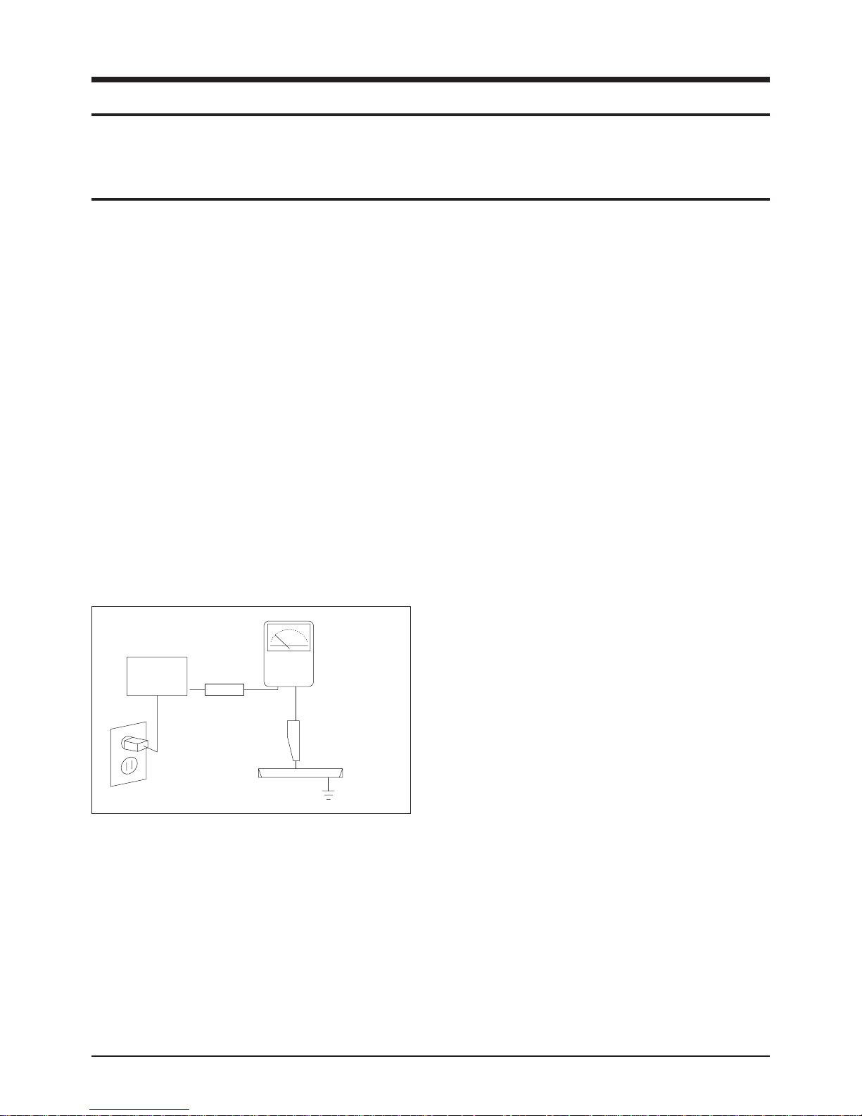
3. Check for Electricity Leakage (Figure 1-1)
Warning: Do not use an insulated transformer for checking the leakage. Use only those current leakage testers
or mirroring systems that comply with ANSIC 101.1 and
the Underwriter Laboratory's specifications (UL1410,
59.7).
Fig. 1-1 AC Leakage Test
4. A high voltage is maintained within the specified limits
using safety parts, calibration and tolerances. When
voltage exceeds the specified limits, check each special
part.
5. Warning for Engineering Changes:
Never make any changes or additions to the circuit
design or the internal part for this product.
Ex: Do not add any audio or video accessory
connectors. This might cause physical damage.
Furthermore, any changes or additions to the original
design/engineering will invalidate the warranty.
6. Warning - Hot Chassis:
Some TV chassis are directly connected to one end of
the AC power cord for electrical reasons.
Without insulated transformers, the product can only be
repaired safely when the chassis is connected to the
earthed end of the AC power source.
To make sure the AC power cord is properly connected,
follow the instructions below. Use the voltmeter to
measure the voltage between the chassis and the
earthed ground. If the measurement is over 1.0V, unplug
the AC power cord and change the polarity before reinserting it. Measure the voltage between the chassis
and the ground again.
7. Some TV chassis are shipped with an additional
secondary grounding system. The secondary system is
adjacent to the AC power line. These two grounding
systems are separated in the circuit using an
unbreakable/unchangeable insulation material.
8. When any parts, material or wiring appear overheated or
damaged, replace them with new regular ones
immediately. When any damage or overheating is
detected, correct this immediately and make a regular
check of possible errors.
9. Check for the original shape of the lead, especially that
of the antenna wiring, any sharp edges, the AC power
and the high voltage power. Carefully check if the wiring
is too tight, incorrectly placed or loose. Never change the
space between the part and the printed circuit board.
Check the AC power cord for possible damages. Keep
the part or the lead away from any heat-emitting
materials.
Precaution
Samsung Electronics 1-1
To avoid possible damages or electric shocks or exposure to radiation, follow the instructions below with regard to safety,
installation, service and ESD.
1. Precaution
1-1 Safety Precautions
(READING SHOULD
DEVICE
UNDER
TEST
EXPOSED METAL
2-WIRE CORD
ALSO TEST WITH
PLUG REVERSED
(USING AC ADAPTER
PLUG AS REQUIRED)
TEST ALL
SURFACES
LEAKAGE
CURRENT
TESTER
NOT BE ABOVE
0.5mA)
EARTH
GROUND

10. Safety Indication:
Some electrical circuits or device related materials
require special attention to their safety features, which
cannot be viewed by the naked eye. If an original part is
replaced with another irregular one, the safety or
protective features will be lost even if the new one has a
higher voltage or more watts.
Critical safety parts should be bracketed with ( ).
Use only regular parts for replacements (in particular,
flame resistance and dielectric strength specifications).
Irregular parts or materials may cause electric shock or
fire.
Precaution
1-2 Samsung Electronics
!

1. The service instructions are printed on the cabinet, and
should be followed by any service personnel.
2. Make sure to unplug the AC power cord from the power
source before starting any repairs.
(a) Remove or re-install parts or assemblies.
(b) Disconnect the electric plug or connector, if any.
(c) Connect the test part in parallel with the electrolytic
capacitor.
3. Some parts are placed at a higher position than the
printed board. Insulated tubes or tapes are used for this
purpose. The internal wiring is clamped using buckles to
avoid contact with heat emitting parts. These parts are
installed back to their original position.
4. After the repair, make sure to check if the screws, parts
or cables are properly installed. Make sure no damage is
caused to the repaired part and its surroundings.
5. Check for insulation between the blade of the AC plug
and that of any conductive materials (i.e. the metal
panel, input terminal, earphone jack, etc).
6. Insulation Check Process: Unplug the power cord from
the AC source and turn the switch on. Connect the insulating resistance meter (500v) to the AC plug blade.
The insulating resistance between the blade of the AC
plug and that of the conductive material should be more
than 1 ㏁.
7. Any B+ interlock should not be damaged.
If the metal heat sink is not properly installed, no
connection to the AC power should be made.
8. Make sure the grounding lead of the tester is connected
to the chassis ground before connecting to the positive
lead. The ground lead of the tester should be removed
last.
9. Beware of risks of any current leakage coming into
contact with the high-capacity capacitor.
10. The sharp edges of the metal material may cause
physical damage, so ensure wearing protective gloves
during the repair.
Precaution
Samsung Electronics 1-3
Warning 1: First carefully read the "Safety Instruction" in this service manual.
When there is a conflict between the service and the safety instructions, follow the safety instruction at all times.
Warning 2: Any electrolytic capacitor with the wrong polarity will explode.
1-2 Servicing Precautions

1-3 Static Electricity Precautions
1. Some semi-conductive ("solid state") devices are
vulnerable to static electricity. These devices are known
as ESD. ESD includes the integrated circuit and the field
effect transistor. To avoid any materials damage from
electrostatic shock, follow the instructions described
below.
2. Remove any static electricity from your body by
connecting the earth ground before handling any
semi-conductive parts or ass'ys. Alternatively, wear a
dischargeable wrist-belt.
(Make sure to remove any static electricity before
connecting the power source - this is a safety instruction
for avoiding electric shock)
3. Remove the ESD ass'y and place it on a conductive
surface such as aluminum foil to prevent accumulating
static electricity.
4. Do not use any Freon-based chemicals.
Such chemicals will generate static electricity that
causes damage to the ESD.
5. Use only grounded-tip irons for soldering purposes.
6. Use only anti-static solder removal devices.
Most solder removal devices do not support an
anti-static feature. A solder removal device without an
anti-static feature can store enough static electricity to
cause damage to the ESD.
7. Do not remove the ESD from the protective box until the
replacement is ready. Most ESD replacements are
covered with lead, which will cause a short to the entire
unit due to the conductive foam, aluminum foil or other
conductive materials.
8. Remove the protective material from the ESD
replacement lead immediately after connecting it to the
chassis or circuit ass'y.
9. Take extreme caution in handling any uncovered ESD
replacements. Actions such as brushing clothes or lifting
your leg from the carpet floor can generate enough static
electricity to damage the ESD.
Precaution
1-4 Samsung Electronics
CAUTION
These servicing instructions are for use by
qualified service personnel only.
To reduce the risk of electric shock do not
perform any servicing other than that contained in the
operating instructions unless you are qualified to do so.

Precaution
Samsung Electronics 1-5
1-4 Installation Precautions
1. For safety reasons, more than two people are required
for carrying the product.
2. Keep the power cord away from any heat emitting
devices, as a melted covering may cause fire or electric
shock.
3. Do not place the product in areas with poor ventilation
such as a bookshelf or closet. The increased internal
temperature may cause fire.
4. Bend the external antenna cable when connecting it to
the product. This is a measure to protect it from being
exposed to moisture. Otherwise, it may cause a fire or
electric shock.
5. Make sure to turn the power off and unplug the power
cord from the outlet before repositioning the product.
Also check the antenna cable or the external connectors
if they are fully unplugged. Damage to the cord may
cause fire or electric shock.
6. Keep the antenna far away from any high-voltage cables
and install it firmly. Contact with the high-voltage cable or
the antenna falling over may cause fire or electric shock.
7. Check the basics of the screen test.
- Image position/size, Tilt adjustment

1-6 Samsung Electronics
MEMO
Product Specification
Samsung Electronics 2-1
2. Product Specification
2-1 Product Features
Block Specfication Core Parts Remark
CRT
- Slimmer than a conventional CRT
Thickness Comparison: Conventional: 495mm → Slimfit:365mm
Vixlim CRT
RF Part - Digital + Analog Tuner (Built-In DTV Tuner)
NIM Tuner
X242H
(MPEG Decoder)
Power
- Input Voltage: AC110V
- Standby: Equal to or Less than 3W
Video
- DHC IC Adopted
- NTSC 3.58, ATSC
- 3D Comb Filter
DHC,X242H
(MPEG Decoder)
Audio
- Output : 10W x 2
- Function : SRS, Dolby Digital
MSP 4450K,TDA7297
Cabinet - New Front and Back Cabinets
FPTV LookingDesign
Black Bezel 2Tone
Color Design
New Design
Other
- Development Grade: Grade 3
- Prototype Model: TXT3093WHX/XAA
- Progressive, Digital All Format Input Support : 1080i, 720P, 480P, 480i
- Software Upgrade using the USB Port on the Back Panel
■ Major Functions of the Core Components
- TEA6425: RF-CVBS, AV, 480i, Y (Super) Switching and Monitor
- CXA2165: Component 1,2 Switch
- MST3387: 480p, 720p, 1080i Signal ADC, 2 HD
- X242H: Control of Overall System Board Operatio
- MSP4450K: SiF, Analog Audio, Digital Audio Signal Input and Decod
Product Specification
2-2 Samsung Electronics
2-2 Key Features
■ H/W Configuration
- DTV Module: 24C16, S3F84BB, MST3387, MSP4450K, 24C256, X242H, 74LS157, SPDIF, SP3232, CXA2165, 74LVTN16373,
KFG5616, MX29LV160, 4H551638,TEA6425
- Main: KA393, STV9381 (D-Glass)
- TM Block: RF Switch, HALF NIM Tuner
- Sound Amp: TDA7297 (SGS Thomson: DIP 16 Pin)
- SMPS Controller: STR-X6759F
- DTV All Format Display: ATSC
- DHC IC, 2HDMI
■ S/W Configuration
- Digital ATSC
- V-Chip, Favorite CH, Label CH
- Digital Dolby AC3 5.1 Second Signal Processing
- Clear QAM
■ Picture
- System: NTSC 3.58 / ATSC
- Progressive Scan
- On Screen Menu: OSG
- Dynamic Black Level Expansion, CTI, VM
- Auto Kinetic Bias (AKB)
■ Sound
- System: Stereo
- Sound Equalizer
- Virtual Dolby (DTV), SRS TSXT Sound
- AVL, Melody, Auto Stereo, Auto Mute
- Speaker: 1 Way x 2
- Output: 10W x 2
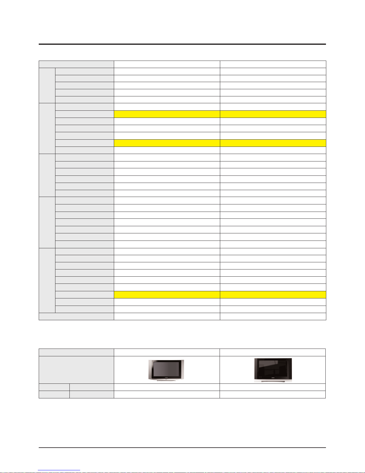
Model Name TXT3093WHX/XAA
Dimensions (mm)
TV
(Main Body)
934(Width) x 406(Depth) x 568(Height)
Weight 43kg
Adopted Display Device High Contrast Instantaneous Scan Type
Receiving Channels
Broadcast Signal Standard: NTSC-M / ATSC Type
Channels 1 ~ 135
CATV Channels: Channel 1~125
VHF, UHF: 75Ω Coaxial
AC 110V, 60Hz
Antenna IN 180W
Power IN
0 ~ 40℃
Power Consumption Insulation-Type Switching Method
Operating Temperature 10W + 10W
Rectification Method
Remote Control: IrDA Type
UHF/VHF Electronic Tuner Fine Tuning: Electronic
Electronic Function Control

Product Specification
Samsung Electronics 2-3
- AVL , Melody , Auto Stereo , Auto Mute
- Speaker : 1Way x 2
- Output : 10W x 2
■ Feature
- Auto program , Sleep timer , Clock
- V chip
- Zoom, Wide, Blue Screen, Color Tone
- Closed Caption(CC1-4/Text1-4)
- Picture Shift(HD Source)
■ In/Out Terminals
- Side: 1 CVBS Input, 1 S-VHS Input
- Rear: 2 RF Inputs, 1 CVBS Input & 2 Component Inputs
2 Component Inputs: 480i, 480P, 720P, 1080i
1 Monitor Out, 1 Anynet Port, 1 Optical Output
■ Remote Control
- Universal: TM87C
■ Power Supply
- 120V Only
■ Power Consumption
- Standby: Equal to or Less than 3W
- Max Power: 150W (32 Inch) / 120W (29 Inch)
Product Specification
2-4 Samsung Electronics
2-3 Specifications Analysis
■ Common Info
■ Option Info
Chassis K63A K71A
Basic
Product Form FLAT CRT FLAT CRT
Digital TV Digital Digital
Digital Display 1080i/720p 480p 1080i/720p 480p
Screen Size 32 32
Aspect Ratio 16:09 16:09
Video
Progressive Scan
○ ○
Digital Comb Filter 3D-COMB 3D-COMB
Screen Pitch 0.73(HI-FINE) 0.73(HI-FINE)
Digital Screen Noise Removal
○ ○
Color Adjustment (AKB)
○ ○
Visual Quality Enhancement DNle X
3:2 Pull Down Support
○ ○
Audio
Bass/Treble/Balance
×
X
EQ 5 Bands 5 Bands
Automatic Volume Level (AVL)
○ ○
Surround X X
Speaker System Direct Direct
Speaker Output 10W+10W 10W+10W
Function
Dual Screen Function
×
X
Double Screen
×
X
Caption English English
Still Image
×
X
Jack Auto Detection
×
X
Electronic Program Guide (EPG)
○ ○
Network Anynet
×
Ports
Antenna IN Rear:2 Rear:2
External IN Rear:1, Side :1 Rear:1, Side:1
S-Video Side:1 Side:1
Digital Signal IN (Y/Pb/Pr) Rear:2 Rear:2
PC
×
X
DVI
×
X
HDMI
○
O
Digital Audio OUT
○
O
Video OUT/Audio OUT Rear:1 Rear:1
Remote Controller TM87 TM87C
Model TX-S3079WH TX-T3093WH
Design
Visual Quality Digital Comb Filter 3D-COMB 3D-COMB
Port HDMI
○
O
Product Specification
Samsung Electronics 2-5
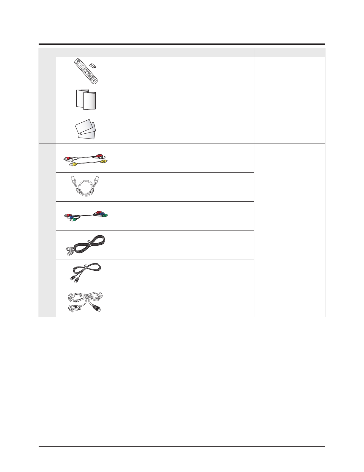
2-4 Accessories
Accessories Item Item code Remark
Supplied Accessories
Remote Control
Batteries
AA59-00411A
4301-000103
Samsung Service center
Owner's Manual
Safety Guide Manual
AA68-03739A
AA68-03242F
Warranty Card
Registration Card
AA68-00371C
AA68-03870A
Accessories that can be purchased
additionally
Video Cable /
Audio Cable
-
Electronics Store/
Internet shopping mall
Antenna Cable -
Component Cable -
Optical Cable -
HDMI Cable -
HDMI/DVI Cable -

2-6 Samsung Electronics
MEMO

Alignment & Adjustment
Samsung Electronics 3-1
3. Alignment & Adjustment
3-1 Service Instruction
1. General Adjustment :
In general, a color TV can provide ideal visual quality by adjusting the basic settings such as the vertical size, horizontal size,
focus, etc.
Display a black and white picture on the screen to check if the picture is clearly displayed.
If there are some 'spotted' points on the screen when displaying a black and white picture, degauss the screen using the
degauss coil. If the spotted points remain, re-adjust the purity and the convergence. This completes the basic performance
examination.
Notice.
■ These adjustments and the check list are only applied to K71A chassis-applied models.
■ Only use 110V for the measurement set. It is recommended using an insulation transformer when supplying power to
the set so as to prevent shock to the set or to yourself.
■ These adjustment specifications have been created on the basis of the domestic K71A chassis-applied remote control
model. Some of the contents may be changed subject to the sales location and the product specifications.
2. When replacing the System Board :
Since the software is loaded to the flash memory of the system board, check the version of the software after replacing the
board.
To check the version of the software, select Menu-Settings-Function Help-Settings and press the "Information Display" key on
the remote control. The software information will then be displayed below the OSD menu.
Software Information Representation: MODULE: T_PRIMKR0_1001 represents X242H IMAGE
"PRIME MODEL KOREA ver.1004".
MICOM: T_PRIMNKR5_0001 represents "PRIME MODEL MICOM ver.1001".
Since the settings such as the Channel Information, Deflection, etc. are saved to the
nvRAM, you have to recheck the Channel Information and Deflection settings when
replacing the System Board.
3. When Replacing the Main: Tilt, Focus, Screen Voltage, and W/B Adjustments
4. When Replacing the CRT Ass'y: No adjustments required.
5. When Replacing the Front TACT SWITCH Power Switch: No adjustments required.
6. When Replacing the Side AV: No adjustments required.
7. When Replacing the Control Switch: No adjustments required.
1. To enter Service Mode, press the keys on the remote control according to the following sequence. (in Stand-by status)
Mute → 1 → 8 → 2 → Power On
※ When failing to enter Service Mode, repeat the procedure above.
2. The initial screen of Service Mode.
3. Functions of the Keys within Service Mode
Alignment & Adjustment
3-2 Samsung Electronics
3-2 How to Access Service Mode
MENU Show all menus
▲ / ▼
Move the cursor to select an item.
◀ / ▶
Adjust the selected configuration value
Deflection
DHC Control 1
DHC Control 2
Line Setup
Local Correct
Video Adjust 1
Video Adjust 2
Video Adjust 3
Video Adjust 4
Video Adjust 5
OPTION
CHECK SUM
USER RESET
T_PRIMKR0_XXXX, XXX.XX.XXXX
T_PRIMKR0_XXX
Alignment & Adjustment
Samsung Electronics 3-3
3-3 Factory Data
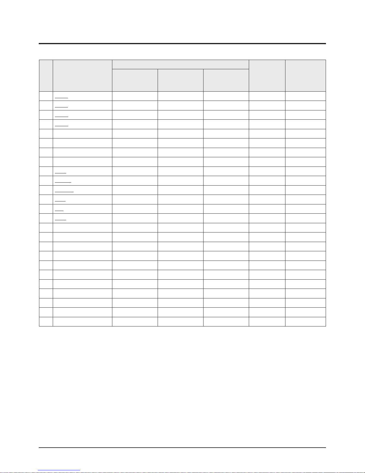
★ The underlined are items applied during the service adjustment. None of the others should be adjusted.
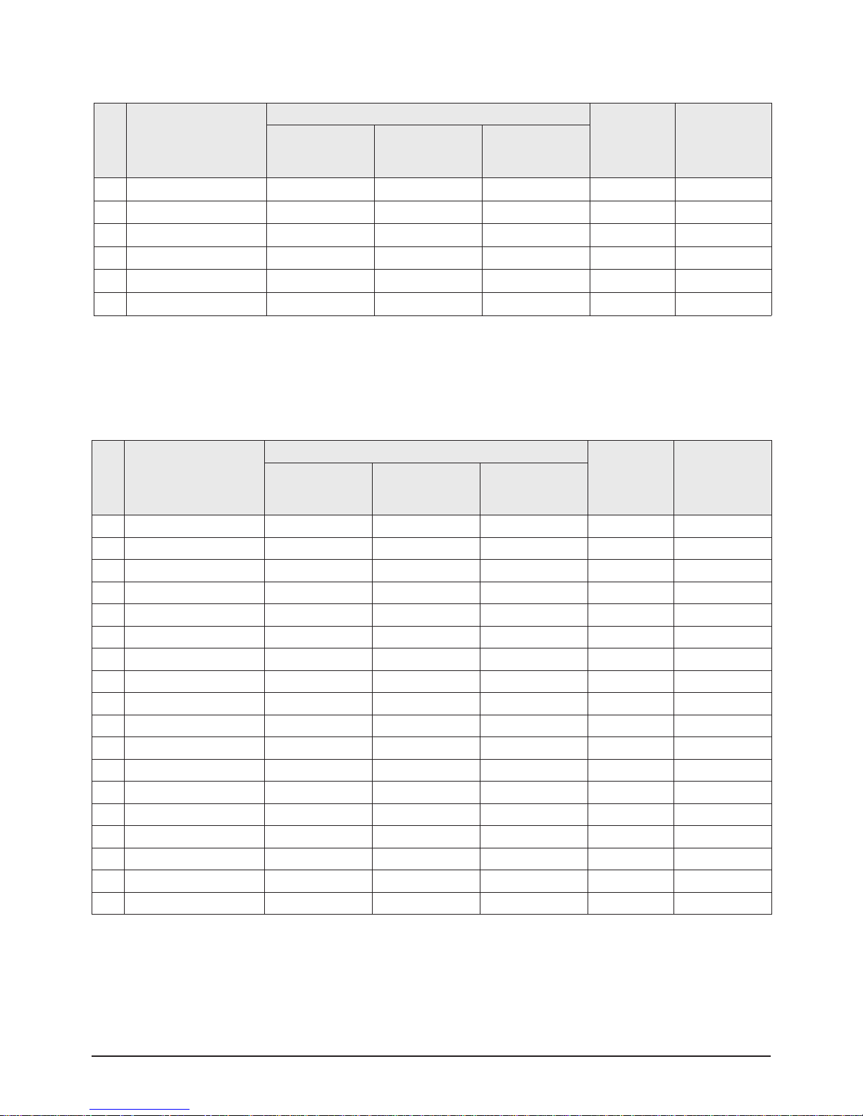
1. Deflection
NO ITEM
Data
Adjust / Fix Remark
32Z40 32Z30
29Z50
29Z40
29Z30
1 V Amp 29 29 42 Adjust
2 V Shift 28 28 25 Adjust
3 H Amp 34 34 29 Adjust
4 H Shift 32 32 35 Adjust
5 V Lin 7 7 5 Adjust
6 Up_ Lin 3 3 3 Adjust
7 Low_Lin 0 0 4 Adjust
8 V SC 2 2 5 Adjust
9 H Par 37 37 40 Adjust
10 Up_ Cor 39 39 38 Adjust
11 Low_ Cor 37 37 36 Adjust
12 H
Tra
40 40 45 Adjust
13 Bow 33 33 28 Adjust
14 Angle 29 29 28 Adjust
15 V Position 15 15 15 Fix
16 CXA Left Blk 42 42 42 Fix
17 CXA Right Blk 26 26 25 Fix
18 CXA Upper Blk 0 0 0 Fix
19 CXA Lower Blk 4 4 4 Fix
20 H Comp 2 2 2 Fix
21 V Comp 5 5 6 Fix
22 Pin Comp 3 3 3 Fix
23 AFC Comp 0 0 0 Fix
24 Horizon Line Cor -20 -20 -20 Fix
25 Output Img Pos -14 -14 -14 Fix
Alignment & Adjustment
3-4 Samsung Electronics
Alignment & Adjustment
Samsung Electronics 3-5
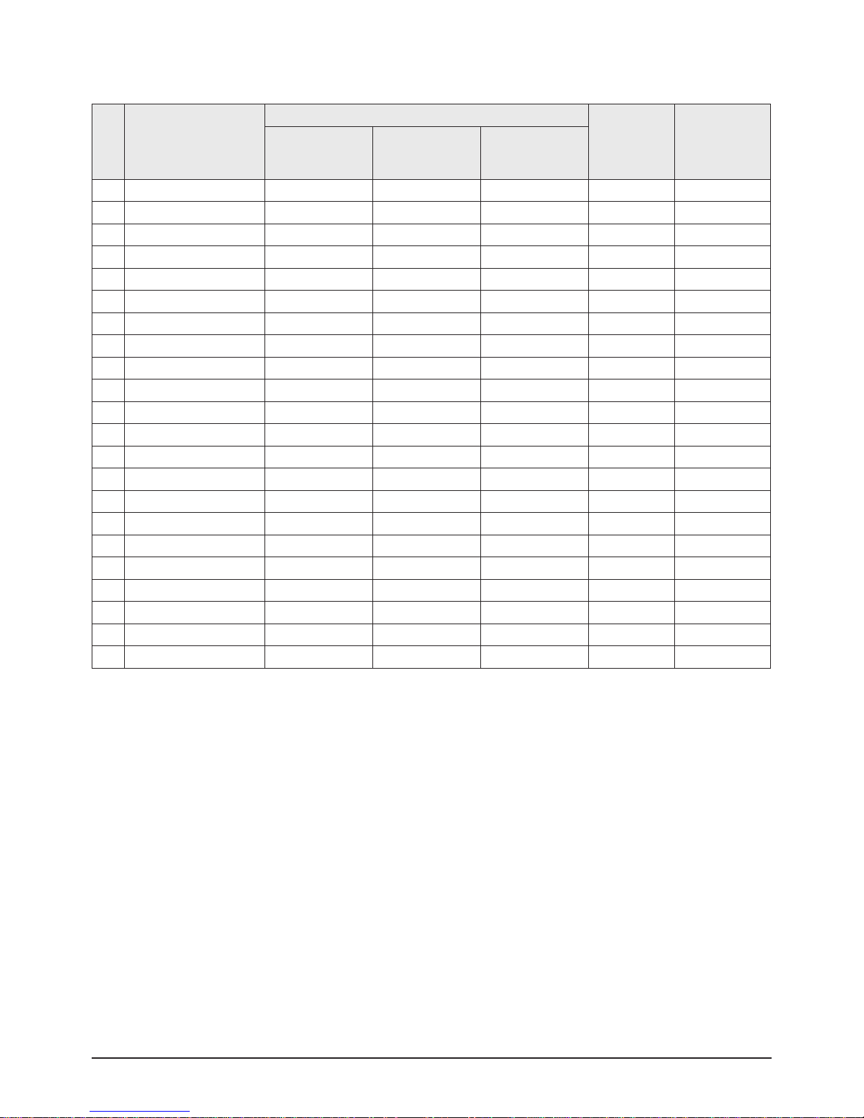
2. DHC Control 1
NO ITEM
Data
Adjust / Fix Remark
32Z40 32Z30
29Z50
29Z40
29Z30
1 Bright Comp En OFF OFF OFF Fix
2 Bright Comp H-Gair 63 63 63 Fix
3 Bright Comp V-Gair 63 63 63 Fix
4 Global Contrast 63 63 63 Fix
5 Ref Line On/Off OFF OFF OFF Fix
6 Inner-Cor En ON ON ON Fix
7 Synm Cor En ON ON ON Fix
8 Local Dst Cor En ON ON ON Fix
9 H Cor En ON ON ON Fix
10 Input Format 7 7 7 Fix
11 Input Img WidthL 128 128 128 Fix
12 Input Img WidthH 7 7 7 Fix
13 Input Img HeightL 28 28 28 Fix
14 Input Img HeightH 2 2 2 Fix
15 input H Blk PeriodL 200 200 200 Fix
16 input H Blk PeriodH 0 0 0 Fix
17 input V Blk Period 19 19 19 Fix
18 Test Patt En OFF OFF OFF Fix
19 Test Patt Form 2 2 2 Fix
20 Output Form 6 6 6 Fix
21 Output Img WidthL 128 128 128 Fix
22 Output Img WidthH 7 7 7 Fix
Alignment & Adjustment
3-6 Samsung Electronics
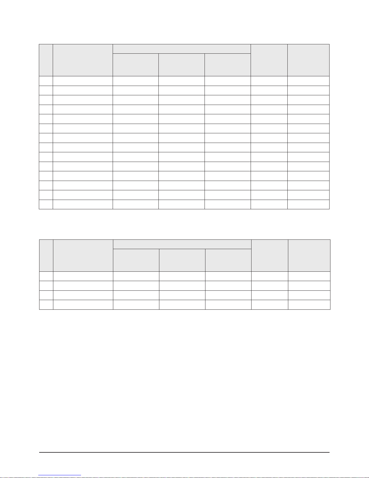
3. DHC Control 2
NO ITEM
Data
Adjust / Fix Remark
32Z40 32Z30HD
29Z50
29Z40
29Z30
1 Horizon Size Cor 127 127 127 Fix
2 Horizon Key Cor 2 2 2 Fix
3 Horizon Pin Cor -15 -15 -15 Fix
4 Horizon Pin S Cor -15 -15 -15 Fix
5 Horizon Pin W Cor 0 0 0 Fix
6 Horizon T Cor -1 -1 -1 Fix
7 Horizon B Cor 5 5 5 Fix
8 Horizon Inn Cor 3 3 3 Fix
9 Horizon Inn S Cor -8 -8 -8 Fix
10 Horizon Inn W Cor 2 2 2 Fix
11 Horizon Inn T Cor -2 -2 -2 Fix
12 Horizon Inn B Cor 4 4 4 Fix
13 Horizon Line S Cor 75 75 75 Fix
14 Horizon Line M Cor 0 0 0 Fix
4. Line Setup
NO ITEM
Data
Adjust / Fix Remark
32Z40 32Z30
29Z50
29Z40
29Z30
1 V Line Index 0 0 0 Fix
2 V Line Poistion 10 10 10 Fix
3 H Line Index 0 0 0 Fix
4 H Line Poistion 0 0 0 Fix
Alignment & Adjustment
Samsung Electronics 3-7
5. Local Correct
NO ITEM
Data
Adjust / Fix Remark
32Z40 32Z30
29Z50
29Z40
29Z30
1 Indicator X 1 1 1 Fix
2 Indicator Y 1 1 1 Fix
3 Point Data 1 1 1 Fix
4 Curve Data 0 0 0 Fix
5 Correct Reset OFF OFF OFF Fix
6 Point Line Data 0 0 0 Fix
NO ITEM
Data
Adjust / Fix Remark
32Z40 32Z30
29Z50
29Z40
29Z30
1 RED Cutoff 29 29 29 Adjust
2 GREEN Cutoff 24 24 24 Fix
3 BLUE Cutoff 34 34 34 Adjust
4 Sub Bright 20 20 20 Adjust
5 Color On/Off ON ON ON Fix
6 CR Offset 32 32 32 Fix
7 CB Offset 32 32 32 Fix
8 RED Drive 41 41 41 Adjust
9 GREEN Drive 32 32 32 Fix
10 BLUE Drive 44 44 44 Adjust
11 Sub Contrast 9 9 9 Adjust
12 Sub Color 16 16 10 Fix
13 Sub Tint 6 6 6 Fix
14 COL Axis 2 2 2 Fix
15 CTI Level 1 1 1 Fix
16 LTI Level 3 3 3 Fix
17 LTI Mode 1 1 1 Fix
18 System 2 2 2 Fix
6. Video Adjust 1
Alignment & Adjustment
3-8 Samsung Electronics
7. Video Adjust 2
NO ITEM
Data
Adjust / Fix Remark
32Z40 32Z30
29Z50
29Z40
29Z30
1 ABL Mode 3 3 3 Fix
2 Gamma 1 1 1 Fix
3 DPIC Level 3 3 3 Fix
4 DC Trans 3 3 3 Fix
5 ABL TH 3 3 3 Fix
6 VM Level 2 2 2 Fix
7 VM Coring 2 2 2 Fix
8 VM f0 0 0 0 Fix
9 VM Limit 2 2 2 Fix
10 VM Delay 2 2 2 Fix
11 SHP CD Gain 1 1 1 Fix
12 SHP f0 ON ON ON Fix
13 SHP f1 Gain 3 3 3 Fix
14 Pre/Over 0 0 0 Fix
15 AKB Timing 15 15 15 Fix
16 S ABL 2 2 2 Fix
17 P ABL 15 15 15 Fix
18 Picture Limit 3 3 3 Fix
Alignment & Adjustment
Samsung Electronics 3-9
8. Video Adjust 3
NO ITEM
Data
Adjust / Fix
480i 480p 720p 1080i
1 VIDEO_MUTE_TIME 8 8 8 8 8 8 Fix
2 RED_CUTOFF 126 126 126 126 126 126 Fix
3 GREEN_CUTOFF 108 108 108 96 96 96 Fix
4 BLUE_CUTOFF 127 127 127 127 127 127 Fix
5 Phase 0 0 0 0 0 128 Fix
6 RED_GAIN 188 188 188 188 188 188 Fix
7 GREEN_GAIN 192 192 192 192 192 192 Fix
8 BLUE_GAIN 188 188 188 188 188 188 Fix
9 PLLDIV_H 53 53 53 53 103 137 Fix
10 PLLDIV_L 9 9 9 9 1 7 Fix
11 PLLGAIN 1 1 1 4 11 11 Fix
12 CLPDLY 8 8 8 8 56 56 Fix
13 CLPDUR 8 8 8 8 32 32 Fix
14 HSOPW 24 24 24 24 48 48 Fix
15 SYNC_CTRL 64 64 64 64 64 64 Fix
16 SOGMID_CTRL 205 205 205 205 205 205 Fix
17 SEP_THR 32 32 32 32 32 32 Fix
18 PRECST 4 4 4 4 4 4 Fix
19 POSTCST 14 14 14 14 14 14 Fix
20 ADC_BW0 68 68 68 51 17 17 Fix
21 ADC_BW1 4 4 4 3 1 1 Fix
22 MDB_Effect 35 35 35 35 35 35 Fix
23 SRS_Dialog 26 26 26 26 26 26 Fix
24 PILOT_Low 128 128 128 128 128 128 Fix
25 PI LOT HIGH 96 96 96 96 96 96 Fix
26 CM_THRESHOLD 1 1 1 1 1 1 Fix
27 AduioDelay 45 45 45 121 121 121 Fix
Alignment & Adjustment
3-10 Samsung Electronics
9. Video Adjust 4
NO ITEM
Data
Adjust / Fix
RF CVBS/S-VHS
1 IN_PHASE_LINE 24 24 24 Fix
2 IN_PHASE_FRAME 26 26 26 Fix
3 OUT_PHASE_LINE 12 12 12 Fix
4 OUT_PHASE_FRAME 22 22 22 Fix
5 CORING 3 3 3 Fix
6 LUMA_BW 0 0 0 Fix
7 CHROMA_BW 3 3 3 Fix
8 CKILL_TH1 48 48 48 Fix
9 CKILL_TH2 80 80 80 Fix
10 LUMA_GAIN 522 522 522 531 Fix
11 LUMA_OFFSET 622 622 622 Fix
12 CR_GAIN 522 522 522 532 Fix
13 CR_OFFSET 0 0 0 Fix
14 CB_GAIN 522 522 522 532 Fix
15 CB_OFFSET 0 0 0 Fix
16 HUE 1024 1024 1024 Fix
17 Y_DELAY_POS 0 0 0 Fix
18 Y_DELAY_NEG 12 12 12 Fix
19 CR_DELAY_POS 0 0 0 Fix
20 CR_DELAY_NEG 13 13 13 Fix
21 CB_DELAY_POS 0 0 0 Fix
22 CB_DELAY_NEG 13 13 13 Fix
23 NOISE_ME Enter Enter Enter Fix
24 AGC Manual_Gain 538 538 538 538 Fix
25 X240_DAC_Contrast 57 57 57 57 Fix
26 X240_DAC_Color 50 50 50 50 Fix
Alignment & Adjustment
Samsung Electronics 3-11
NO ITEM
Data
Adjust / Fix Remark
COOL1 COOL1 COOL1
1 Cool2 RC Offset 1 1 1 Adjust x:264 , y:268 15,000K
2 Cool2 BC Offset 2 2 2 Fix
3 Cool2 RD Offset 1 1 1 Adjust
4 Cool2 BD Offset 3 3 3 Adjust
5 Cool 1 RC Offset 0 0 0 Fix x:269 , y:274 13,000K
6 Cool 1 BC Offset 0 0 0 Fix
7 Cool 1 RD Offset 0 0 0 Fix
8 Cool 1 BD Offset 0 0 0 Adjust
9 Normal RC Offset 1 1 1 Fix x:276, y:283 10,000K
10 Normal BC Offset -5 -5 -5 Adjust
11 Normal RD Offset 2 2 2 Adjust
12 Normal BD Offset -5 -5 -5 Fix
13 Warm 1 RC Offset 3 3 3 Fix x:295 , y:295 9,300K
14 Warm 1 BC Offset -7 -7 -7 Fix
15 Warm 1 RD Offset 1 1 1 Fix
16 Warm 1 BD Offset -10 -10 -10 Fix
17 Warm 2 RC Offset 3 3 3 Fix x:315 , y:315 6,500K
18 Warm 2 BC Offset -10 -10 -10 Fix
19 Warm 2 RD Offset 3 3 3 Fix
20 Warm 2 BD Offset -9 -9 -9 Fix
21 Movie Warm 1 RC OS 5 5 5 Fix
22 Movie Warm 1 BC OS -7 -7 -7 Fix
23 Movie Warm 1 RD OS 4 4 4 Fix
24 Movie Warm 1 BD OS -12 -12 -12 Fix
25 Movie Warm 2 RC OS 5 5 5 Fix
26 Movie Warm 2 BC OS -11 -11 -11 Fix
27 Movie Warm 2 RD OS 4 4 4 Fix
28 Movie Warm 2 BD OS -17 -17 -17 Fix
29 4:3 size H_shift offset 23 23 23 Fix
10. Video Adjust 5
Alignment & Adjustment
3-12 Samsung Electronics
# Added item
Item DATA Var/Fix
White
Balance
High : x : 269± 3 y : 274± 3 Y : 45± 3
Low : x : 269± 3 y : 274± 3 Y :1.2± 0.3
White Balance (Standardization Applied)
Screen Voltage
The Highest Voltage among RK, GK and BK
180Vp-p - 3V
screen voltage
11. OPTION
NO ITEM
Data
Adjust / Fix Remark
32Z40 32Z30
29Z50
29Z40
29Z30
1 LNA ON ON ON Fix
2 HDMI Number 1 0 0 Fix
0:No HDMI, 1:1-HDMI,
2:2-HDMI
3 DDC_Protect ON ON ON Fix
HDMI EDIE data sub-micom p/g
download EEPROM write_protect off
4 EER Reset - - - Fix
5 242 Test Pattern - - - Fix
6 WATCH DOG ON ON ON Fix
7 AGC_ ON OFF OFF OFF OFF Fix
8 SHOP_MODE OFF OFF OFF Fix
9 ScreenSize 4:3 OFF OFF ON Fix
Model inch option(p_size)
(wide CRT:off, 4:3 CRT;on)
Alignment & Adjustment
Samsung Electronics 3-13
■DHC IC Description
The DHC IC is image processor for geometry correction and brightness uniformity compensation. The input of DHC processor is digital R,G,B,
and the output of DHC processor is analog Y,Pb,Pr signal.
ITEM EXPLANATION DATA
Bright Comp En Bright uniformity compensation enable OFF
Bright Comp En H-Gain
Horizontla gain of BUC, whitch is used to Compensate the brightness distortion in
horizontal direction
63
Bright Comp En V-Gain
Horizontla gain of BUC, whitch is used to
Compensate the brightness distortion in vertical direction
63
Global Contrast Globa contrast of BUC 63
Red Line On/Off Red line display enable OFF
Inner Cor En Inner direction correction ebable ON
Sym Cor En Symmetry distortion correction enable ON
Local Dst Cor En local distortion correction enable ON
H Cor En
Enable/Disable the whole DHC geometry correction and Brightness uniformitity
compensation
ON
Input Format Input format select 7
Input Img WidthL Input width of image 128
Input Img WidthH Input width of image 7
Input Img HeightL Input height of image 19
Input Img HeightH Input height of image 200
Input H Blk PeriodL Input horizontal blanking period 2
Input H Blk PeriodH Input horizontal blanking period 0
Input V Blk PeriodL Vertical blanking period 19
Test Patt En Test pattern enable OFF
Test Patt Form Test pattern format 6
output Img WidthL width of output image 128
output Img WidthH width of output image 7
Alignment & Adjustment
3-14 Samsung Electronics
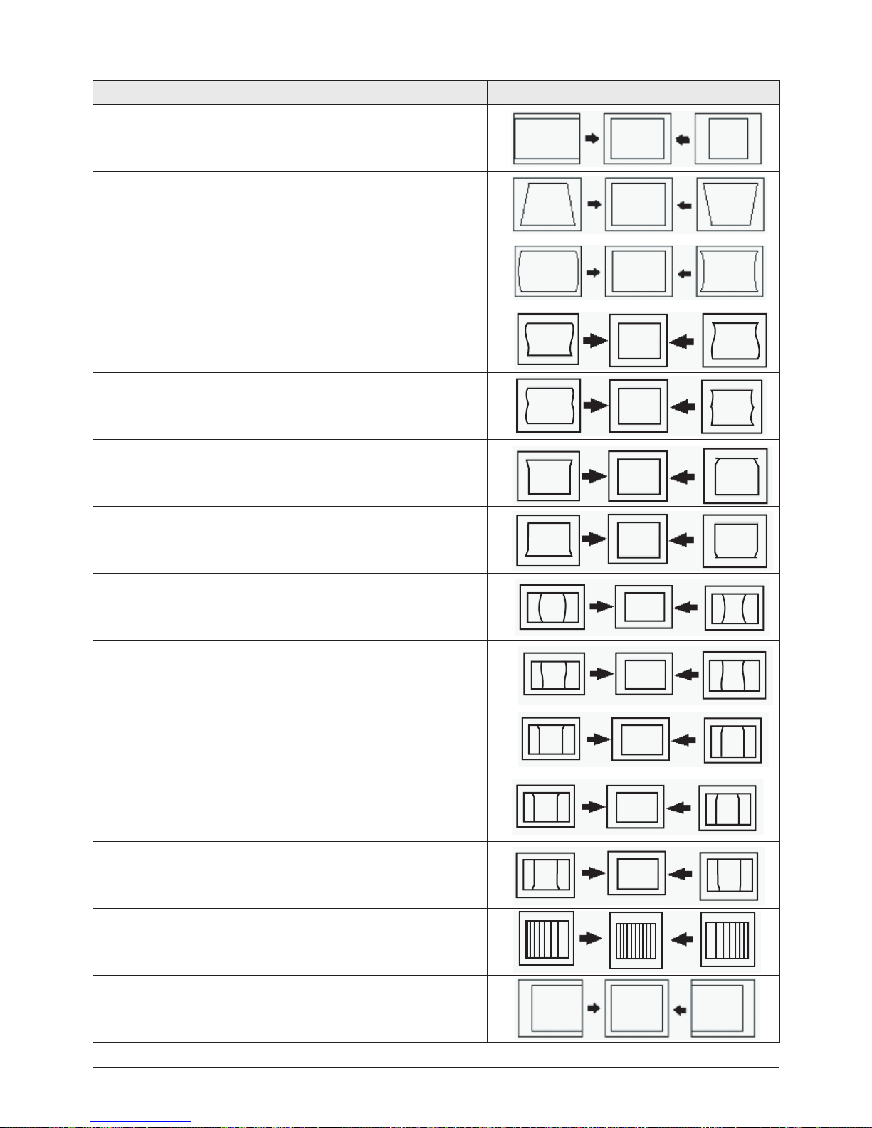
ITEM EXPLANATION DATA
Horizon Size Cor Horizontal size correction
Horizon Key Cor Horizontal Keystone correction
Horizon Pin Cor Horizontal Pincushion correction
Horizon Pin S Cor Horizontal Pincushion S correction
Horizon Pin W Cor Horizontal Pincushion W correction
Horizon T Cor
Horizontal corner correction at the top of
image
Horizon b Cor
Horizontal corner correction at the bottom of
image
Horizon Inn Cor Inner pincution correction
Horizon Inn S Cor Inner pincution s correction
Horizon Inn W Cor Inner pincution w correction
Horizon Inn T Cor Inner corner correction at the top of imag
Horizon Inn B Cor Inner corner correction at the bottom of imag
Horizon line Cor Horizontal linearity correction
output Img H Pos Horizontal posituin correction
 Loading...