


Samsung TXN3245FP, TXN2668WHF, TXN2775HF, TXN2745FP, TXN2670WHF Owner’s Manual
Owner's
Instructions
Warning ! Important
Safety Instructions
CAUTION
CAUTION: TO REDUCE THE RISK OF ELECTRIC SHOCK, DO NOT
REMOVE COVER (OR BACK). NO USER SERVICEABLE PARTS INSIDE.
REFER SERVICING TO QUALIFIED SERVICE PERSONNEL.
This symbol indicates high voltage is present inside It is
dangerous to make any kind of contact _ith any inside part of
this producl
This symbol alerts you that important literature concerning
operation and maintenance has been included with this product¸
Note to CATV s._s/em installer: This reminder is provided 1o call CATV system
inslallerg allention 1o Article 820-40 of lhe Nalional Electrical Code (5eclion 54- of
Canadian Electrical Code, Part I), lhal provides guidelines lor proper grounding
and, in particular, specifies lhal lhe cable ground shall be connected lo the
grounding sxslem (if lhe building as close to the point of cahle enlry as praclical
Caution: FCC/C SA rx:gulati, ms state that an.v unauthorized cha_ges or .lod{_ica-
tio!_s to this equipmem ma.v _oid the user_ authori(v to operate it.
Ca_*tion: To pre_enl electric shock, match the wide blade of ph*g to tile _ide slot,
and filll.v ius_ rt tile phtg.
Attelai, m: pour e_ iter Ies chocs elecoiques, introduirc la lame Ie plus large de la
fiche darts Ia borlw comspondante de la prise et pousser jusqu'au _tmd.
Important: One Federal Court has held that unauthorized recording of
copyrighted TV programs is an inlringement of US copyright lax_s
Certain Canadian programs may also he copyrighted and any unauthorized
recording in x_hole or in part *nay be in violation of these rights
To prexent damage which may result in fire or electric shock
hazard, do not expose this appliance to rain or moisture.
As an ENERGY STAR Parmer,
Samsung Eleclronics America, Inc. has delennincd Ihat fl_is pr_xluct or pRxlucl
2 m_xM meels file ENERGY STAR guidelines for energy effick,nc)_
Thank You for Choosing Samsung
Thank you for choosing Samsung! _-\_urnew Samsung TV represents die latest in television
technologp We designed it with easy-to<tse on-screen menus and closed captioning capabili-
ties, making it one of tile best ploducts in its class We are proud to offer you a Doduct that
will provide convenient, dependable seivice and enjoyment for years to come
Important Safety Information
_ Always be careful x<hen using your TV receixer To reduce tile risk of fire, electrical shock,
and other itj uries, keep these safety precautions in mind when installing, using, and
maintaining your machine
• Read all saf_'ty and operating instructions before operating your TV
• Keep the salcty and operating instructions tor future rebrence
• Heed all warnings on the TV receiver and in tile operating instructions
• Follow all operating and use instructions
• Unplug the TVreceiver from the wall outlet before cleaning Use a damp cloth; do not use
liquid or aerosol cleaners
• Never add any attachments and/or equipment without approval of tile manufacturer Such
additions can increase tile risk of fire, electric shock, or other pemonal i*j urp
• Do not use the TV receiver where contact with or immerqion in water is a possibilit}; such as
near bath tubs, sinks, washing machines, swmmmlg pools, etc
• Do not place tile TV on an unstable cart, stand, tripod, bracket, or
table where it can fall A fidlmg TV can cause serious i_jury to a
child or adult, and serious damage to tile appliance Use only with
acmt, stand, uipod, bracket, or table recommended by the manu-
factmei or sold with the T\{ Follow the manufacturel_ insuuc-
tions when mounting the unit, and use a mounting accessory rec-
ommended by tile manufacturer Move the TV and cart with care
Quick stops, excessive folce, and uneven surfaces can make tile
unit and cart unsteady and likely to oveitmn
• Provide ventilation for the TV receiver Tile unit is designed with slots in the cabinet for ven-
tilation to protect it from overheating Do not block these openings with any object, and do
not place the TV receiver on a bed, sofa, rug, or other similar surface Do not place it near a
radiator or heat resister If yogi place the TV receiver on a rack or bookcase, ensure that there
is adequate ventilation and that you've followed tile manufacturer_ instructions for mount-
ins
• Operate your TV receiver only from tile type of power source indicated on the marking label
If you are not sine of tile type of power supplied to your home, consult your appliance dealei
or local power compans:
• Use only a grounded or polarized outlet For your safeb; this TV is equipped with a polarized
ahemating current line plug having one blade widei than the other This plug will fit into tile
powei outlet only one wa> If yogiare unable to inseit the plug fidly into the outlet, try
reveising tile plug If tile plug still does *lot fit, contact your electrician to replace your outlet
3
• Protect the power cord Power supply cords should he routed so that they v,on't be _aalkecl
on or pic_clled by obiects placed on or against them Pay particular attention to cords at
plugs, comenience receptacles, arid the point whele they exit from the unit
• Uc@ug the TV from the wall outlet and disconnect the antecma or cahle system during a
lightnic_gstorm o1 v.hen left unattec<led arid Utlused for long peliods ot time This vvillpre
vent damage to the unit due to lighming and powel line stages
• Avoid ovahead power lines An outside amenna systenl should not be placed in the vicinity
of ovedlead power lines ol othel elecuic light o1 power circuits o1 vvhele it can fall into such
power lines ol circuits When installing an outside amenna systenl, he extlenlely caretul to
keep flora touching the powel lines or cilcuits Contact with such lines can he tatal
• Do riot overload the wall outlet or extec_sioncords Overloading can resuh itl fire or electric
shock
• Do not insert anything through the openings in tile unit, where they can touch dangerous
vohage points or damage parts Nexer spill liquid of any kind on the T\{
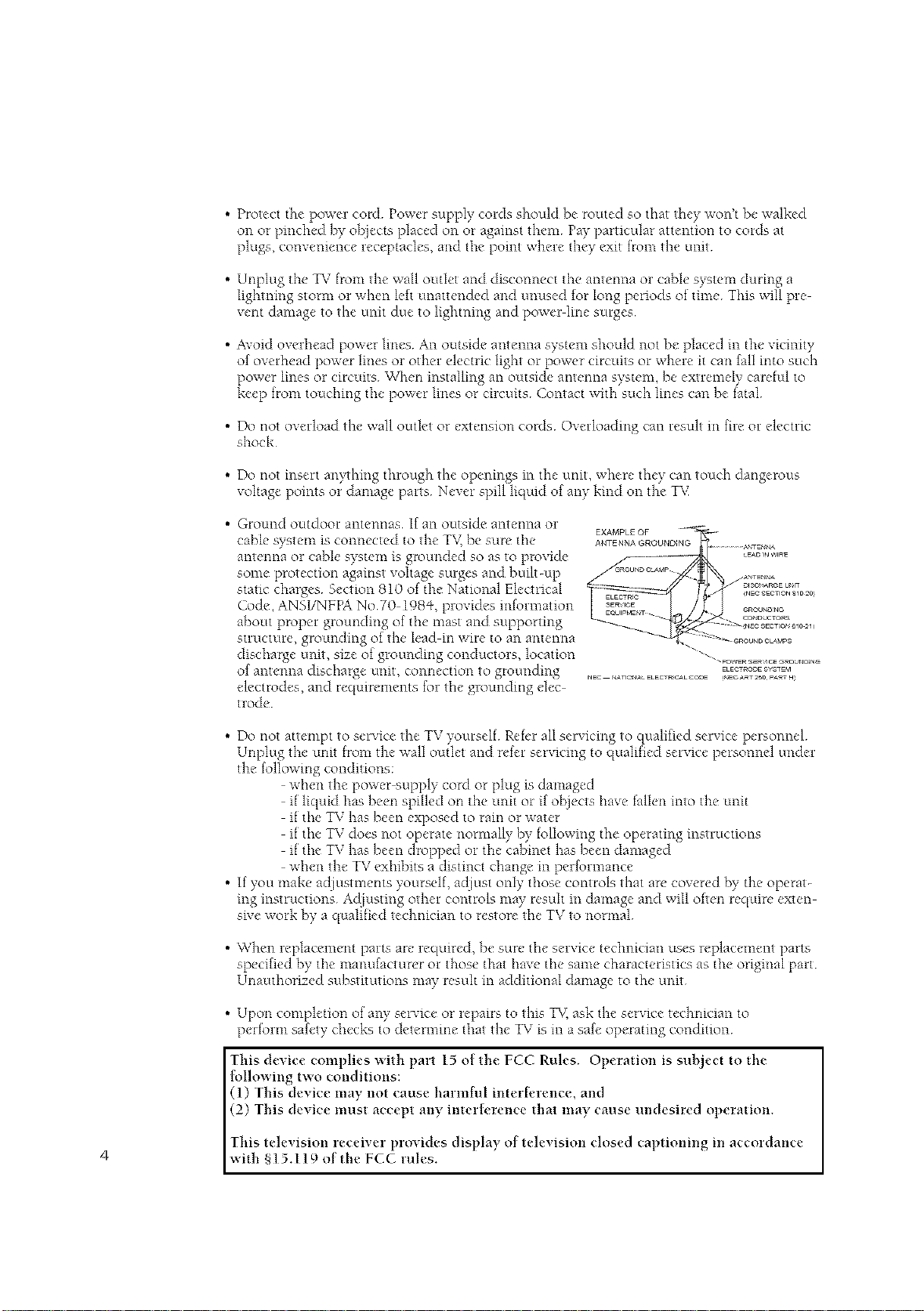
• Ground outdoor antennas If an outside antenna or
cable system is connected to the T\( he sure the ANTENNAG_OOND_NG..............._:J_N_
antecma or cable system is groutlded so as to provide /_ _-- _E.,O,._,,,R_
some protectioc_ against vohage surges and built-up ___°_"_°_ _._,N_
Cool°, ANSI/NFPA No70 I98q _,ploxicles icdomlation _]',_ ..... _.......
static: charges Section 810 ot the National Elecuical _v_ ..... _2o%_%_,%_,'_]0:0
about propel glounding of tile nlast and supporting - °_'°"°_?_
EXAMPL£ OF _ -
s.uctule,g o.nd ngoft>1,.din,,iF,.toan,,nten l , .....
discharge unit, size of grounding conductols, location "" ""- ............ .............
of ant°tins discharge unit tion to groutlcling _ ._OOE_.*'_
electrodes, and requirements tol the grounditlg dec-
uode
• Do not attempt to service the TV yourselt Ret_'r all servicing to qualified service personnel
Unplug the unit flora the wall outlet and retcr servicing to qualified service personnel under
the k_llowing conditions:
• If you make adiustments yourself, acliust only those controls that are covered by the operat-
ing instructions Acliusting other controls nmy result m damage and will otten require exten
sn'e work by a qualified technician to restore tile TV to normal
• When replacement parts are required, he sure tile service technician uses replacement parts
specified by tile manufacturer or those that have tile same characteristics as tile original [)art
Unauthorized substitutions may resuh in additional damage to tile unit
: , connec ._° t4_r<S_aCELECrRG,_LC_E,_,ECA_r250p4RrH
when the power supply cord or plug is damaged
it liquid has been spilled on the unit or if obiects have tallen into the unit
it tile TV has been exposed to ram or water
it tile TV does not operate normally by following tile operating instructions
it tile TV has been dropped or tile cabinet has heen damaged
when the TV exhibits a distinct change in performance
• Upon completion of an,,.'serxice or repairs to this T_,;ask the service technician to
pertoHn safety checks to detern'mle that the TV is in a safe operating condition
This device complies with part 15 of the FCC Rules. Operation is suhlect to the
lollowing two conditions:
(1) This device may not cause harmfiH interh'rence, and
(2) This device must accept any interh, rence that may cause undesired operation.
This televisiori receiver prmides display of tele,,'ision closed captioning in accordance
4 with §15.119 of t he FCC rules.
Important Warranty Information
Regarding Television Format
Viewing
Standard screen format televisions (4:3, the aspect ratio of the screen width to height) are
primarily designed to view standard format full-motion video The images displayed on
them should primarily be in the standard 4:3 ratio f,_rmat and constantly moving
Displaying stationary graphics and images on screen, such as the dark top and bottom
letterbox bars (wide screen pictures), should be limited to no more than 15% of the total
television viewing per week
b\qde screen format televisions (16:9, the aspect ratio of the screen width to height) are
primarily designed to view wide screen format full motion video The images displayed
on them should primarily be in the wide screen 16:9 ratio format, or expanded to fill the
screen if your model off¢'rs this frature, and constantly moving Displaying stationary
glaphics and images on screen, such as the dark side bars on non expanded standard
format television video and programming, should be limited to no more than 15% of the
total television viewing per week
Additionall),, viewing other stationary images and text such as stock market reports,
video game displa),s, station logos, web sites or computer graphics and patterns, should
be limited as described above for all televisions Displaying any stationary images that
exceed the above guidelines can cause uneven aging of picture tubes (CRTs) that leave subtle,
but permanent burned m ghost images in the television picture To avoid this, vary the pro
glare ruing
and images, and primarily display full screen moving images, not stationary patterns or
dark bara On television models that offrr picture sizing fratures, use these controls to
view the diff.'rent formats as a fldl screen picture
Be careful m the selection and duration of television formats used fol viewing Uneven
CRT aging as a result of format selection and use, as well as other burned-m images, is
not covered by your Samsung limited warrant),
5
CONTENTS J
Chapter 1: Your New TV ................ 8
List ot Featmc,s ........................................... 8
Familiadzing l\_ursclf with The TV ............................ 9
Chapter 2: Installation ................. 14
Conn_'cting VHF and UHF Antennas ......................... 14
Connecting Cable TV ..................................... 15
Connecting a VCR ........................................ 18
Connecting a DVD Player (480iP+80p) ........................ 20
Connecting a Digital 157 Set-Top Box ('+80p/1080i) ............... 21
Connecting a Camcorder ................................... 23
Installing Batteries m the Remote Control ...................... 24
Front Panel Buttons ................................ 9
Side Panvl Jacks .................................. 10
Real Panel Jacks .................................. 11
Remote Contwl ................................... l 2
Antennas with 300 ohm Flat Twin Leads ............... 14
Antennas with 75 ohm Round Leads .................. 15
Separate VHF and UHF Antennas ..................... 15
Cable without a Cahle Box .......................... 15
Connecting to a Cable Box that Descrambles All Channels .... 16
Connecting to a Cable Box that Descrambles Some Channels ..... 16
Com_ecting an S VHS VCR .......................... 19
Connecting a Second VCR to Recoid from the TV ......... 20
Connecting to Y,Pb,Pr .............................. 21
Co*mectmg to DVI (Digital Visual Interface) ............. 22
Chapter 3: Operation .................. 25
Tuining the _' On and Off ................................. 25
Plug & Play Featuie ...................................... 25
Vievdng the Menus and On Screen Displayq .................... 27
Viewing the Menus ................................ 27
\Tiewing the Display ............................... 27
Selecting a Menu Language ................................. 28
Memorizing the Channels .................................. 29
Selecting ti_e Video Signal-source ..................... 29
Storing Channels in Memoiy (Automatic Method) ........ 30
Adding and Erasing Channels (Manual Method) .......... 31
Changing Channels ....................................... 32
Using the Channel Buuons .......................... 32
Directly Accessing Channels ......................... 32
Using the PRE-CH Button to select the Previous Channel 32
Adjusting the Volume ..................................... 32
Using Mute ...................................... 32
Labeling the ChamaeE ..................................... 33
Setting the Clock ......................................... 34
Option I: Setting the Clock Manually .................. 34
Option 2: Using the Local PBS Channel to
Automatically Set the 157 Clock ...................... 35
Customimng the Pictme ................................... 37
Using Automatic Picture Settings ............................ 38
Customimng the Sound .................................... 39
Using Automatic Sound Settingq ............................. 40
Vievdng an External Signal Source ........................... 41
6
CONTENTS [
Chapter 4: Special Features ............. 42
Customizing _\_vuRemote,Lont_ol ........................... 42
SettingUp "_btlrR_'moWControl ro L)DrateYour\CR (or DVD) 42
SettingUp "_\mrR_'moteControl ro L)p_'rat_"Your(hbk" Box ..... 44
Fine Tuning ChamM_ ..................................... 45
LNA (Low Noise Amplifier) ................................. 46
Tilt ................................................... 47
DNIN" (Digital Natural Image engine) ........................ 48
Digital Noise Reduction ................................... 49
Changing the Screen Size .................................. 50
Changing the Color Tone .................................. 51
Using the RSurf Feature ................................... 52
Fleezing the Picture ...................................... 52
Setting the On/Off Timei ................................... 53
Setting the Sleep Timer .................................... 54
Choosing a Multi Channel Sound (MTS) Soundnack ............. 55
Exua sound settings (Tmbo Sound, Sulround, Auto Volume,
Melod> BBEor Woofei) ................................... 56
Viewing Closed Captions .................................. 59
Viewing Pictuie-in-Pict ure ................................. 60
Activating Pictule-in-Picture ......................... 60
Selecting a Signal Source (Exteinal A/V) for PiP .......... 61
Changing the Size of the PiP Window ................. 62
Swapping the Contents of the PiP image and Main image 63
Changing the PIP Channel .......................... 64
Using the VChip (USA) ................................... 65
Setting Up Youi Personal ID Number (PIN) ............. 65
How to Enabl¢'/Disable the \aChip .................... 66
How to Set up Restrictions Using the "TV guidelines" ..... 66
How to Set up Restrictions using the MPAA Ratings:
G, PG, PG 13, R, NC 17, X .......................... 68
How to Reset the TV aftei the VChip
Blocks a Channel (_Eme*genc), Escape") ................ 69
Using the VChip (Canada) ................................. 70
Setting Up Your Personal ID Number (PIN) ............. 70
How to Enable/Disable the \"-Chip .................... 71
How to Set up Restrictions Using the "TV guidelines" ..... 71
How to Set up Restrictions using the MPAA Ratings:
G, PG, PG 13, R, NC 17, X .......................... 73
How to Set up Restrictions Using the Canadian English .... 74
How to Set up Restrictions Using the Canadian French 75
How to Reset the TV aftel the VChip
Blocks a Channel ("Emmgency Escape") ................ 76
Viewing the Demonstration .......................... 77
Chapter 5: Troubleshooting ............. 78
Identifying Problems ...................................... 78
Appendix ............................ 79
Clvaning and Maintaining _\mt TV ........................... 79
Using _\_u_TV m Anothei Lounuy ........................... 79
Specifications ........................................... 79
7
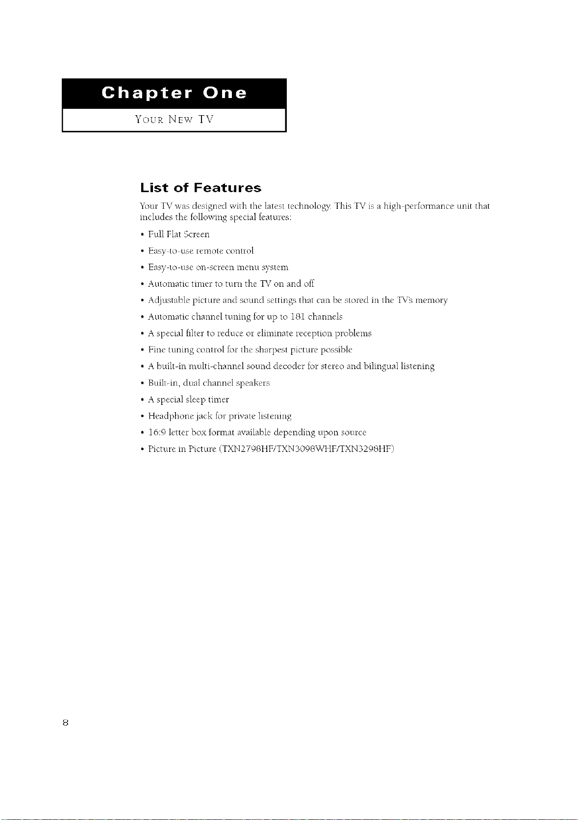
YOURNEWTV
List of Features
_ur TV was designed with the htest tecbnolog_ This TV ix a high per_rmance unit that
includes the tollowing special _atures:
Full Flat Scle_'n
Easy to us_' remow control
Easy to use Oil scrf_ell I_21C'IlH system
Automatic timer to turn the TV on and off
Adjustable, picture" and sound settings that can be stored m the" TVs memory
Automatic cha*mel tuning for up to 18I channels
A special tilter to reduce or eliminate reception problems
Free tuning control for the sharpest picture possible
A built-in muhi channel sound decoder for stereo and bilingual listening
Built-m, dual channel speakers
A special sleep timer
Headphone jack for private listening
16:9 letter box format available depending upon source
Picture m Picture (TXN2798HF/TXN3098WHF/TXN3298HF)
YouP. NEw' TV ]
Familiarizing Yourself with The TV
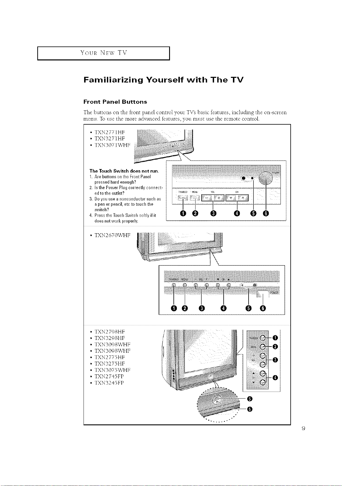
Front Panel Buttons
The buttons on d_c fRmt pand contR}l your TVg basic features, hwludmg the on scR*en
mellU To use _l_e more advanced features, VOLI must use the remote control
• TXN277IHF
• TXNo27IHF
• TXNo07IWHF
The Touch Switch does not run.
1. Are buttons on the FIont Panel
plessed hald enough?
2. Is the Power Plug correctly connect-
ed to the outlet?
3. DO you Use a 11ollcollductor such as
a pen ol pencil, ere to touch the
switch?
does not wolk ploperly.
• TXN2670WHF
00 0 0 0 0
• TXN2798HF
• TXNB298HF
• TXN 3098WHF
• TXN 3098WHF
• TXN2775HF _0
• TXN3275HF
• TXN3075WHF
• TXN27qSFP _0
• TXN32qSFP
9
YOUR NEw TV ]
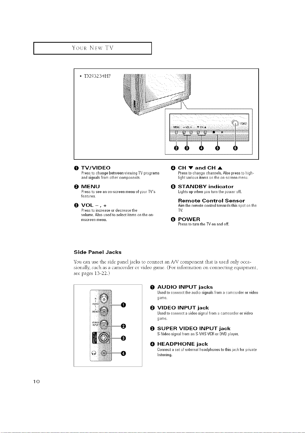
• TXN323_HF
_ %_i iJHiii;;i¸ ZI_i_;
[ •
0 TV/VIDEO
PresstocMngebetweenviewingTVpr0glams
andsignalsfromothercomponents.
0 MENU
Pressto see an oI1-screell meI1u o[ your TV's
fea[tlres.
O VOL -, +
Press to iRcrease 0r deciease the
volume. Also used to select items on the on-
mscreell meRu.
e e 0 0 O
0 CH V andCH A
Plessto changechannels.Alsopresstohigh-
light valious items oil tile o{I-sol ee{1 m e{I tl.
i_ STANDBY indicator
Lightsupwhenyouturnthepoweloff.
Remote Control Sensor
Aim the remote contlol towards this spot ontile
TV.
0 POWER
Plessto turntheTVonandoff.
10
Side Panel Jacks
You can use the side panel jacks to connect an A/V component that is used only occa-
sionall/, such as a camcorder or video game (For information on connecting equipment,
see pages 13 22 )
0
AUDIO INPUT jacks
Used to comlect tile audio signals from a canlcolder or video
game.
O
VIDEO INPUT jack
Used to comlect a video signal f=om a camcordel el video
game.
O
SUPER VIDEO INPUT jack
S-VideosignalfromanS-VHSVCRel DVDpiayeL
0
HEADPHONE jack
Connect a setof extenlal headphones to this iack for plivate
listening.
YOUR NEW TV [
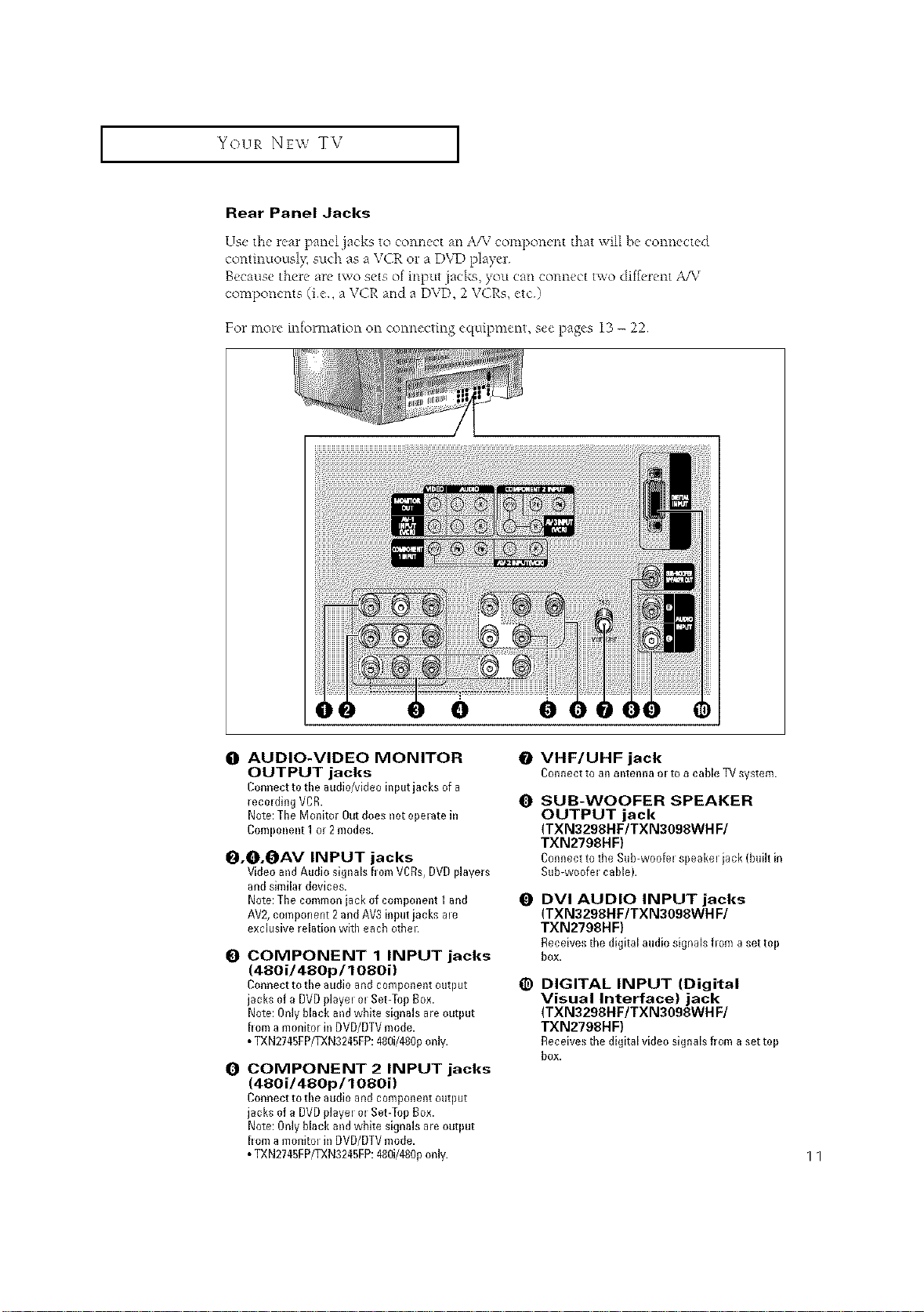
Rear Panel Jacks
Use the rear panel jacks to connect an A/M component that will he connected
continuously, such as a VCR or a DVD player
Because there are two sets of input jacks, you can connect two diff¢-rent A/V
components (ie, a VCR and a DVD, 2 VCRs, etc)
For more information on connecting equipment, see pages 13 - 22
O AUDIO-VIDEO MONITOR
OUTPUT jacks
Connectto the audi0/videoinputjacks of a
recolding VCR.
Note:TheMonitorOutdoesnotoperatein
Component1 or 2modes.
O.O.OAV INPUT jacks
Video andAudio signals bom VCRs,DVDplayers
andshnilar devices.
Note:Tile common iack of component I and
AV2,component 2andAV3 inputiacks ale
exclusive relation witll eacb otbel:
COMPONENT 1 INPUT jacks
(48Oi/480p/108Oi)
Connect to the audio and component output
jacks of a DVDplayel el Set-Top Box.
Note: Only black and white signals are output
bom a monitor in DVD/DTVmode.
• TXN2745FP/TXN3245FP:480i/480ponly.
O
COMPONENT 2 INPUT jacks
(480i/480p/1080i)
Connect to the audio and component output
jacks of a DVDplayel el Set-Top Box.
Note: Only black and white signals are output
born a monitol in DVD/DTVmode.
• TXN2745FP/TXN3245FP:480i/480ponly.
e e
0 SUB-WOOFER SPEAKER
0 DVI AUDIO INPUT jacks
_) DIGITAL INPUT (Digital
VHF/UHF jack
Connect to an antenna el to a cable TV system.
OUTPUT jack
(TXN3298HF/TXN3098WH F/
TXN2798HF)
ConnecttotbeSub-woo(elspeakeliack(buihin
Sub-woo(el cable).
(TXN3298HF/TXN3098WH F/
TXN2798HF)
Receivestbedigitalaudiosignalsflom asettop
box.
Visual Interface) jack
(TXN3298HF/TXN3098WH F/
TXN2798HF)
Receivestbedigitalvideosignalsfroma settop
box.
11
I Your NEW TV I
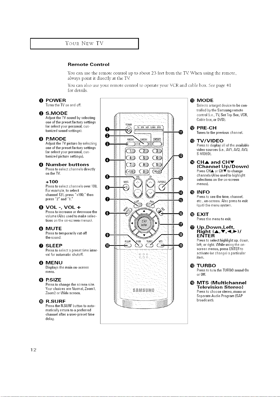
Remote Control
You can use the remote control up to about 23 feet from the T\{ "When using the remote,
always point it directly at the TV
You can also use your remote control to operate your VCR and cable box See page 41
for details
O POWER
TurnstileTVonandoff.
I_ S.MODE
Adiust tile TV sound by selecting
one of tile preset facto H settings
(or select yore pelsonal, cus-
tomized sound settings).
@ RMODE
Adiust tile TVpictm e by selecdng
one oftile preset factoH settings
(orselect yore pelsonal, cus-
tomized picture settingsb
Number buttons
Pless to select cbannels directly
onthe TV.
+1OO
Pless to select cbannels ovel 100.
Fol example, to select
chmme1121, press "+I00," then
pless "2" and "17
I_ VOL -, VOL +
Pless to blcrease 0[ decrease tbe
volume (Also used to make selec-
tions on tbe on-scleen meRusb
0 MUTE
P_essto ternpo_arily cut off
the sound.
O SLEEP
PI ass to select a preset time i{it el-
val for automatic sbuto_.
0 MENU
Displays tbe mabl orl-scIeen
me{lu.
Q P.SIZE
Pless to cbaBIge tbe scleeBI size.
Your cboices are Nolmal, Zooml,
Zoom2 or Wide screen.
(_) R.SURF
Pless tbe R.SURF button to auto-
matically return to a prefened
cballllel ariel a usePpleset time
delay.
O MODE
Selects a talget device to be coil-
trolled by tbe Samsung remote
control (i.e., TV, Set Top Box, VCR,
Cable box, or DVD).
_) PRE-CH
Tunesto tileprevious cbamlel.
_) TV/VIDEO
Pless to display all oftbe available
video sources (i.e., AVI, AV2, AV3,
S-VIDEO).
CHA and CHV
(Channel Up/Down)
Pless CHA or CHV to cbange
cbannels (Also used to bigbligbt
selections on tbe on-screen
menusb
_) INFO
Pless to see tbe time, cbannel,
etc., oR-scIeell. AiS0 press to exit
(quit) tbe menu system.
1_) EXIT
PIess tbe mellu to exit.
_) Up,Down,Left,
Right (A,V.<,I_)/
ENTER
P_essto select bigbligbt tip, down,
left, m ugbt. While usblg tile on-
screen menus, I}less ENTERto
activate (01 cbange) a particular
item.
_) TURBO
Pless to tul ntbe TURBRsound On
or Off.
_) MTS (Multichannel
Television Stereo)
Bless to cb00se stereo, m0110 01
Sol}mate Audio Program (SAP
broadcast).
12
YOUR NEW TV J
Remote Control
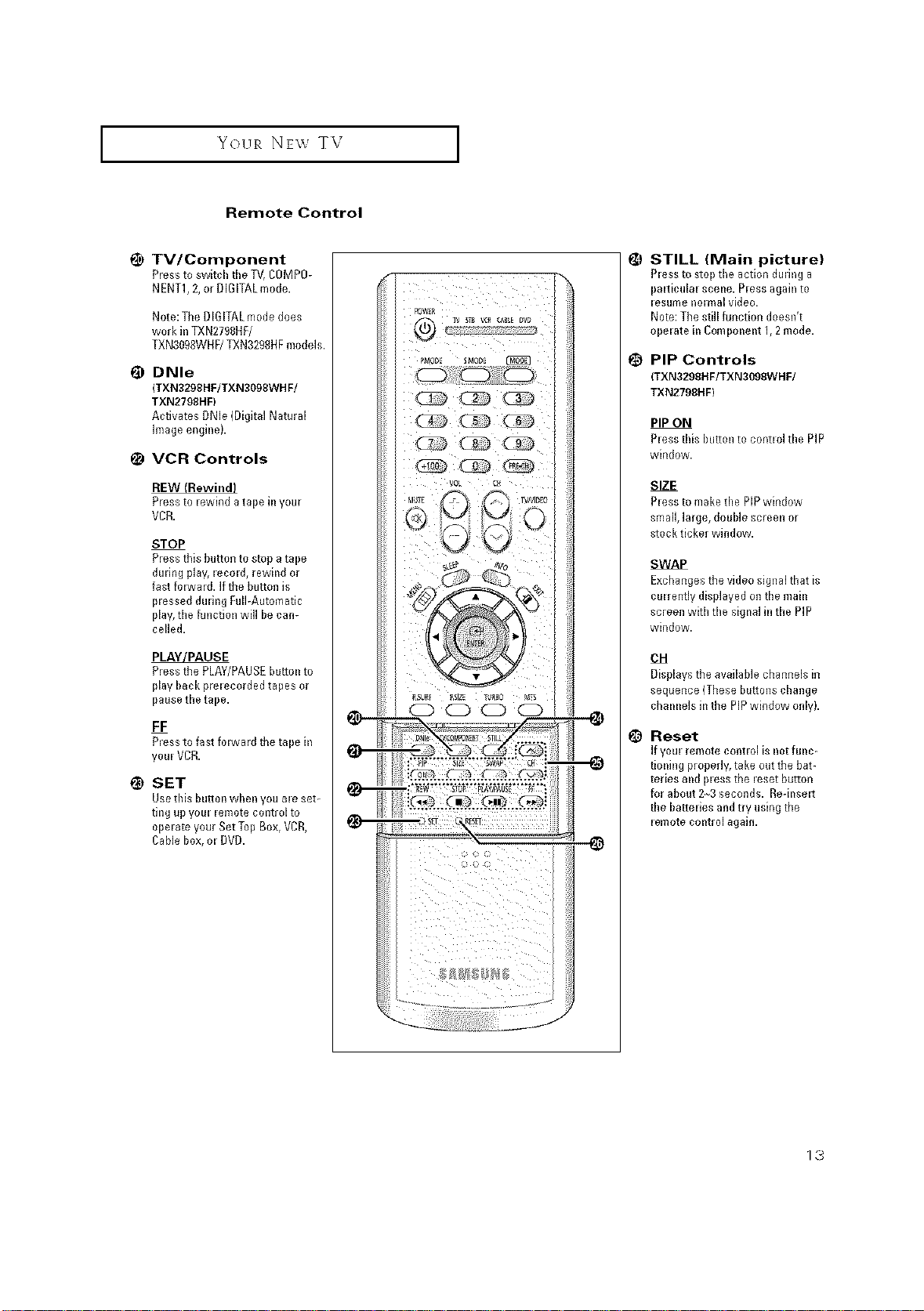
1_ TV/Component
Pressto swkch tile TV,COMP0-
NENT1,2, or DiGiTALmode.
Note:The DIGITALmode does
work in TXN2798DF/
TXN3098WHF/TXN3298HFmodels.
DNle
(TXN3298HF/TXN3098WH F/
TXN2798HF)
Activates DNle (Digital Natural
image engkleL
1_ VCR Controls
Pressto lewkld atape k_your
VCR.
STOP
Pressthis button to stop atape
during play, leco@, rewkld or
fast folward, ifthe bu_tonis
plessed during RdEAutomatic
play,the function will be cal)-
celled.
PLAYJPAUSE
Pressthe PLAY/PAUSEbutt@lto
play back prelecorded tapes or
pause the tape.
FF
P_essto fast forward the tape k_
youl VCR.
_) SET
Usethis button when you ale set-
ting up youl lemote contl olto
opelate your Set Top Box, VCR,
CaNe box, ol DVD.
STILL (Main picture)
Pless to stop tile action during a
palticulal sceile. P_essagain to
lesume nolma[ video,
Note:The still function doesn't
opelate hi Cornpoi_ei_t1,2mode.
PIP Controls
(TXN3299HF/TXN3099WHF/
TXN2798HF)
PIP ON
Pless this button to contlol the PiP
wkld0w.
SIZE
Pless to make the PIPwindow
small, large, double screen or
stock ticker window.
SWAP
Exchangesthe video signal tllat is
culrently displayed on tile mahl
screen with the sigilal in the PIP
window.
OH
Displays the available channels in
sequence (These buttons change
chamlels hi the PiPwindow only).
_) Reset
Ifyoul remote contlol is not fullc-
tioning properly, take outtile bat-
teries alld pless tile leset button
for about 23 seconds. Re-k_selt
the I)attelies andtry using the
lemote contl ol agab).
1,3
INSTALLATION
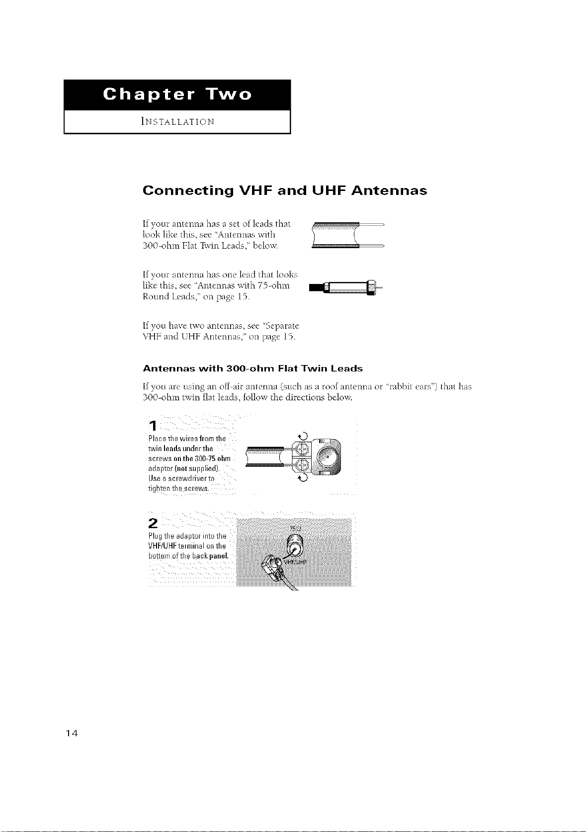
Connecting VHF and UHF Antennas
If your antenna has a set of leads that
look like this, see 'Antennas with
300 ohm Flat Twin Leads," beloxx
If your antenna has one lead that looks
like this, see 'Antenrms with 75 ohm
Round Leads," on page 15
If you have two antemlas, see ¢%eparate
VHF and UHF Antennas," on page 15
Antennas with 300-ohm Flat Twin Leads
If you are using an off air antc, nna (such as a roof antenna ot Chabbit ears') that has
300-ohm tv, in flat leads, follow the cltrections below.
alaee the wiles fi om the
PoJIn leO{Is uRile/lne
;clews on the 300_75 ohm
_OalJiO/inoi SUDDIleQ
USe 0 SCleWi111V_IIO
Ilgrlton In_ SCleWS
Plugthe adaptor into the
VHF/UHFtelminal on the
bottom of the bacl_
14
I INSTALLATION [
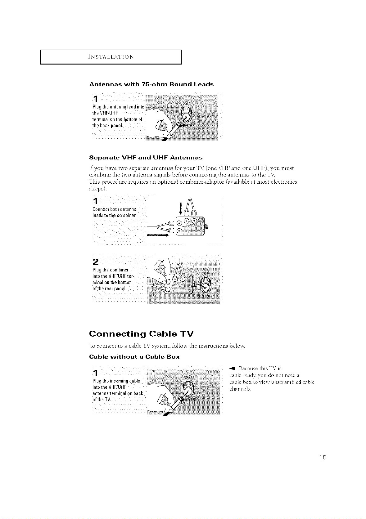
Antennas with 75-ohm Round Leads
Separate VHF and UHF Antennas
If you have two separate antennas for your TV (one VHF and one UHF), you must
combine the two antenna signals before connecting the antennas to the T\<
This procedure requires an optional combiner-adaptor (available at most electronics
shops).
Connect bothantenna
!eadsto the combiner.
2
Plugtile combiner
into the VHF/UHFter-
minal onthe bottom
ofthe rea[ panel
Connecting Cable TV
To connect to a cabb TV system, follo_x the instructions below
Cable without a Cable Box
!
Plug the incoming cab! e cane box to view unscrambled cane
int0the VHF/UHF channels
antenna terminal 0n ba_k
0fthe TV.
4'41 Becaus_ this ]\ is
cab]_le_]_ ¸,you do not need a
15
I INSTALLATION [
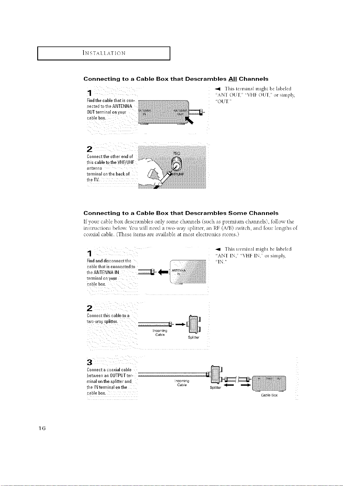
Connecting to a Cable Box that Descrambles All Channels
1
Findtbe cable tbat is con-
nected to tbe ANTENNA
OUTterminal on y0m
tbis cable D the VHF/U
aRtenna
terminal on the back of
the TV.
Connecting to a Cable Box that Descrambles Some Channels
If yore cahl_"box desc'umd>k's only some"channels (such as plemium channds), follow the
inst_Ltctions belov< You will need a two way splitter, an RF (A/B) switch, and fore lengths of
coaxial cable (These items are available at most electronics stores)
",,11 ]his hlmmal might b_ labd_d
"ANT OUT," %q[F OU] ," or simpl} ¸¸,
"OUT"
1
Findand disconnect tbe
cable box.
C0nnect this cable to a
3
Connect acoaxial cable
between an OUTPUTter
minal onth_ splitier and
tbe IN telminal ontbe
cable box.
Cable
Incoming
Cable
]his t_lminal might be labeled
"AN] IN," %qlE _IN," or simplv_
Splitter
Cable Box
1(3
I INSTALLATION I
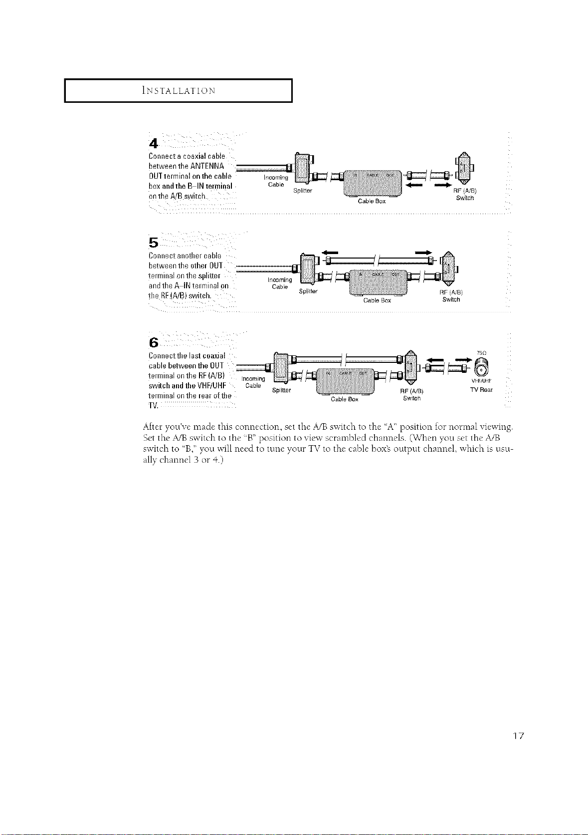
4
Connect a coaxial cable
between the ANTENNA
OUT tm minal on the cable Incomin_
box andtbe B IN terminal Cable _
ontheA/Bswitch. Splttor RF/A/B)
Connect anotber cable _
between the other OUT
terminal on the splitter incoming
andthe A IN tmminal on Cable
the RE(A/B) switch. Splitter RF (A/B)
Cable Box Swtch
Cable Box Switch
Connect tbe last coaxial
75£1
cablebetweentheOUT
terminalonthe RF(A/B) Inoomin
switcbandtbeVHF/UHF Cable
terminalonthe lear o!tile
TV.
Splr_ter RF (A/8)
Cable Box Switch
TV Rear
After you've made this connection, set the A/B switch to the A" position for normal viewing
Set the ,_13 switch to the _B" position to view scrambled channels (WI_en you set the A/B
switch to 'B," you will need to tune your TV to the cable boxE output channel, which is usu
ally channel 3 or _+)
17
I INSTALLATION [
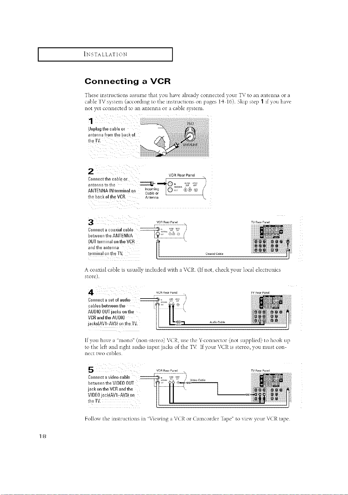
Connecting a VCR
These instruction,s assume that you have alread) connected your TV to an antenna or a
cable TV s)stem (according to tile instructions on [)ages 14- 16) Ski[) step 1 if you haxe
not yet connected to an antenna or a cable system.
JIIplug [no Ca [lie 0[
antenna flora the back of
the TV
vcRR_arpan_
VGR Rear }_ano
rgR_arPanel
]l)nnectthe ( tDle C
antenna [o ine
ANTENNA IN temlina
me Da_oftheVCR
Connect a coaxial cable
Jetween the ANTENNA
._mi.. !Q;"F' _,)® ®
Cab e el
antenna
3UTtemlinalontheVCR
ano IRe antenna
te/minalontheT\ Co_,_c_b_
lI
A coaxial cable is usually included with a VCR. (It not, check your local electronics
store).
vCRRea_Panel
eonnectasetofaudi 0 _L,_, _' I_ /I
AUDIO OUTjacks on t!le
VDD andthe AUDIO
cables between the t_ [
jacks(AV !,-AV3) on th e TV.
Aud_O_ble
TV Rea_Pa_el
If you have a 'mono" (non stereo) VCR, use tile Y connector @ot supplied) to hook up
to the left and right audio input jacks of tile TV If your VCR is stereo, you must con-
nect two cables.
VOR Rear pa_l
Connect a v de0 cab e _ i_ W }
jack ontheVDRandthe ' k
betweentheVIDE0OUT l" [l '_-'_
VIDEOjack(AVI_AV3)on
TV Re_ p_r_el
t!)eTV. II //
Follow the instructions in "Viewing a VCR or Camcorder Tape" to vie_x Four VCR tape
18
I INSTALLATION [
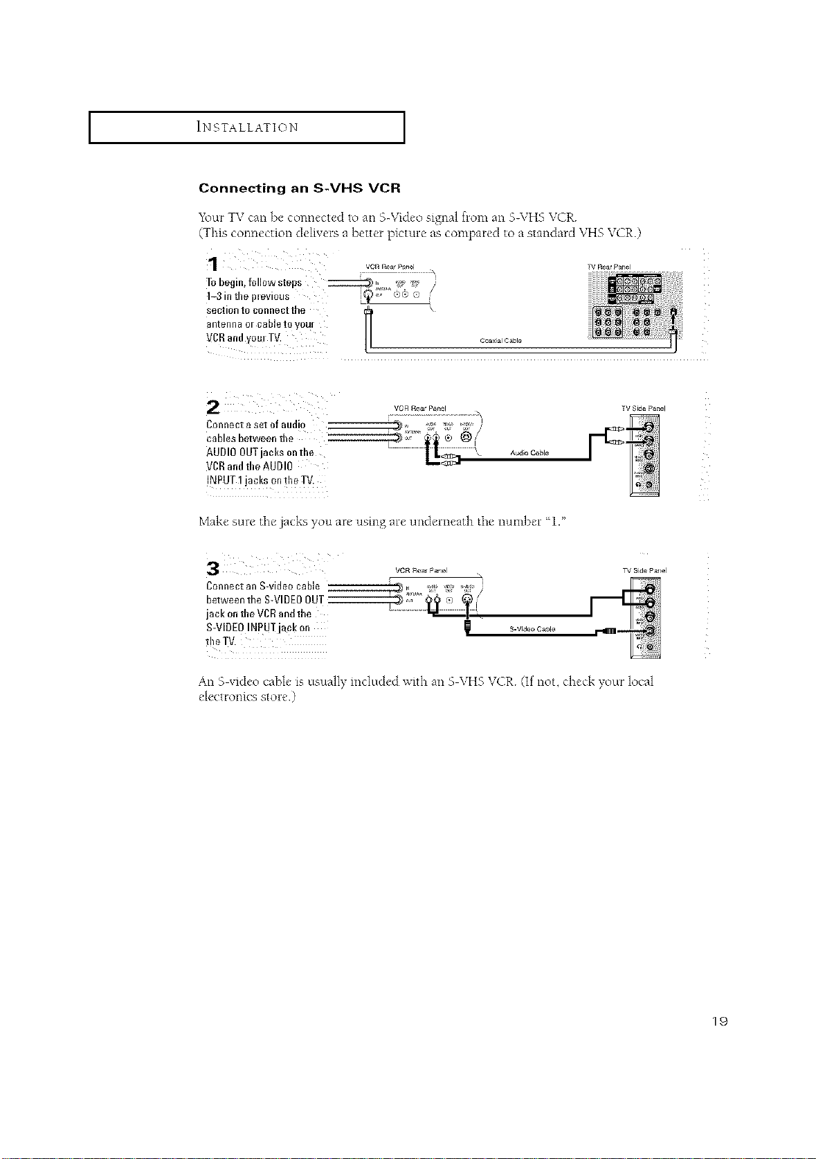
Connecting an S-VHS VCR
1\mr TV can be connected to an 5Wideo signal from an 5-\ZH5 VCR
(This connection delivers a better picture as compared to a standard VHS VCR.)
1
To begin, followsteps ::::::::::::g_ l_ _ i_" '_:" /
1_3in the il=evious S_), ®e e
section to connect tbe \
_ntenna or cable to yOUr
_CR and yoreTV.
VCR £ear P_el
Connect a set of audio
cables between the
AUDIO OUTjacks onthe
VCRandthe AUDIO
INPUT 1jacks ontke TV.
Make sure tile jacks you are using are underneath tile number 1."
3
Connect an S-video cable
between the S-VIDEOOUT
jack on the VCDandthe
S-VIDEOINpUT jack on
VCR _ea_ PaNel
Coax_alC_ble
Audio Cable
S.Vide° Cable
TVRearPanel
_VSide Panel
TV Side P_ael
An S video cable is usuall) included with an S VHS VCR (If not, check your local
e ec ro llCS S Ole )
19
I INSTALLATION [
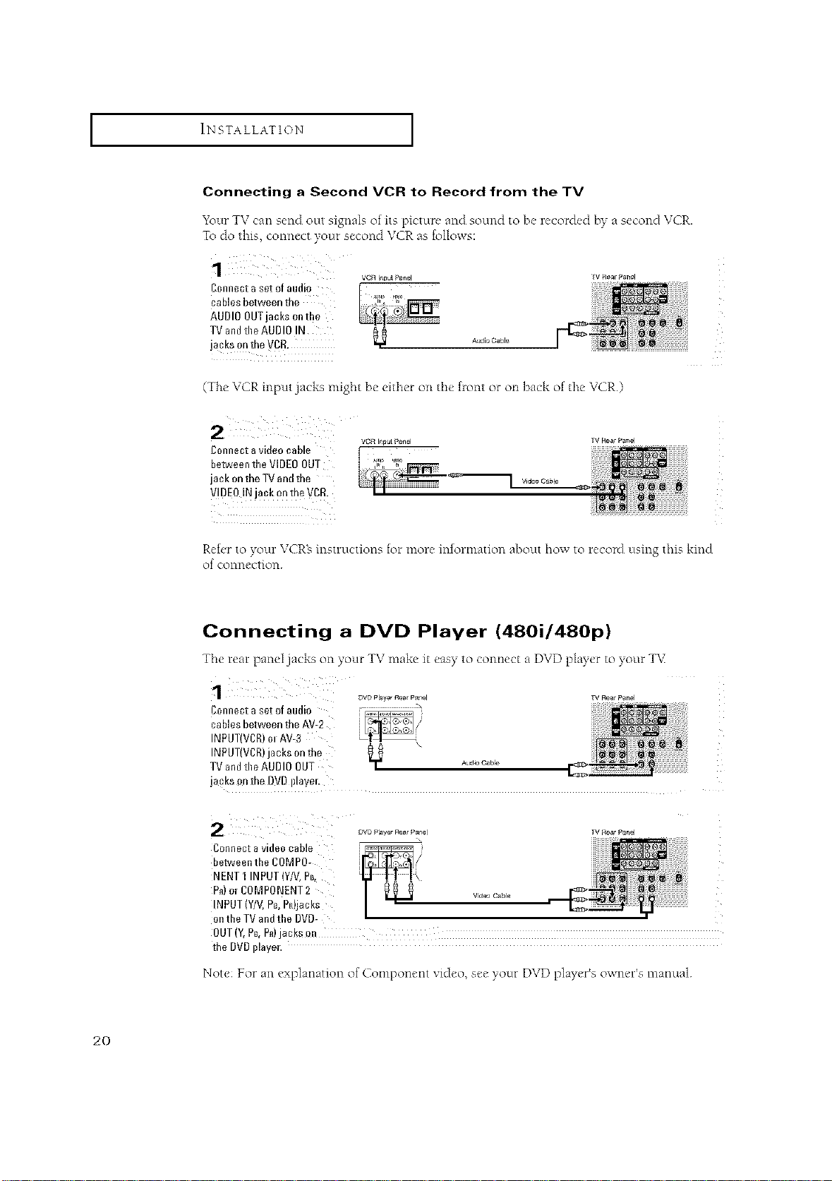
Connecting a Second VCR to Record from the TV
Your TV can send out signals of its picture and sound to be recorded by a second VCR.
To do this, connect your second VCR ;is follows:
vc_ i_pulPanel
cables between the
Connect aset of audio ,._, _
AUDIO OUTjacks onthe
TV andtheAUDIO IN
jacks on the VCR.
A_ioCaN_
Tv_earPanel
(The VCR input jacks might be either on tile front or oil back of tile VCR.)
Connect avideo cable
between the VIDEO OUT
jack onthe TV and the
V!DE0 INjack on the VCD.
Video C_le
TV RearPanel
Refer to your VCRs instructions for more information about how to record using this kind
of connection
Connecting a DVD Player (480i/480p)
Tile rear panel jacks on your TV make it easy to connect a DVD player to your TV
DYe Player r{_ar P_n,_l
_/Rea_Panel
Connect aset of audio
cables between the AV-2
INPUT(VCR)m AV-3
INPUT(VCR)jacks on the
TV andthe AUDIO OUT
y Aud4° Cable
jacks on the DVDillayel,
i_/R_ar Panel
Connect a video cable
between the COMP0-
NENTI INPUT(Y/V,PB_
P_)or C0MPONENT 2
INPUT (WV,Pc,Pn)jacks
w_e_ Cable I_
ontheTVandthe DVD-
the DVDplayer.
Not< For an explanation of Component vi&,o, se_" your DVD play,'r% owm, l s manual
20
I INSTALLATION [
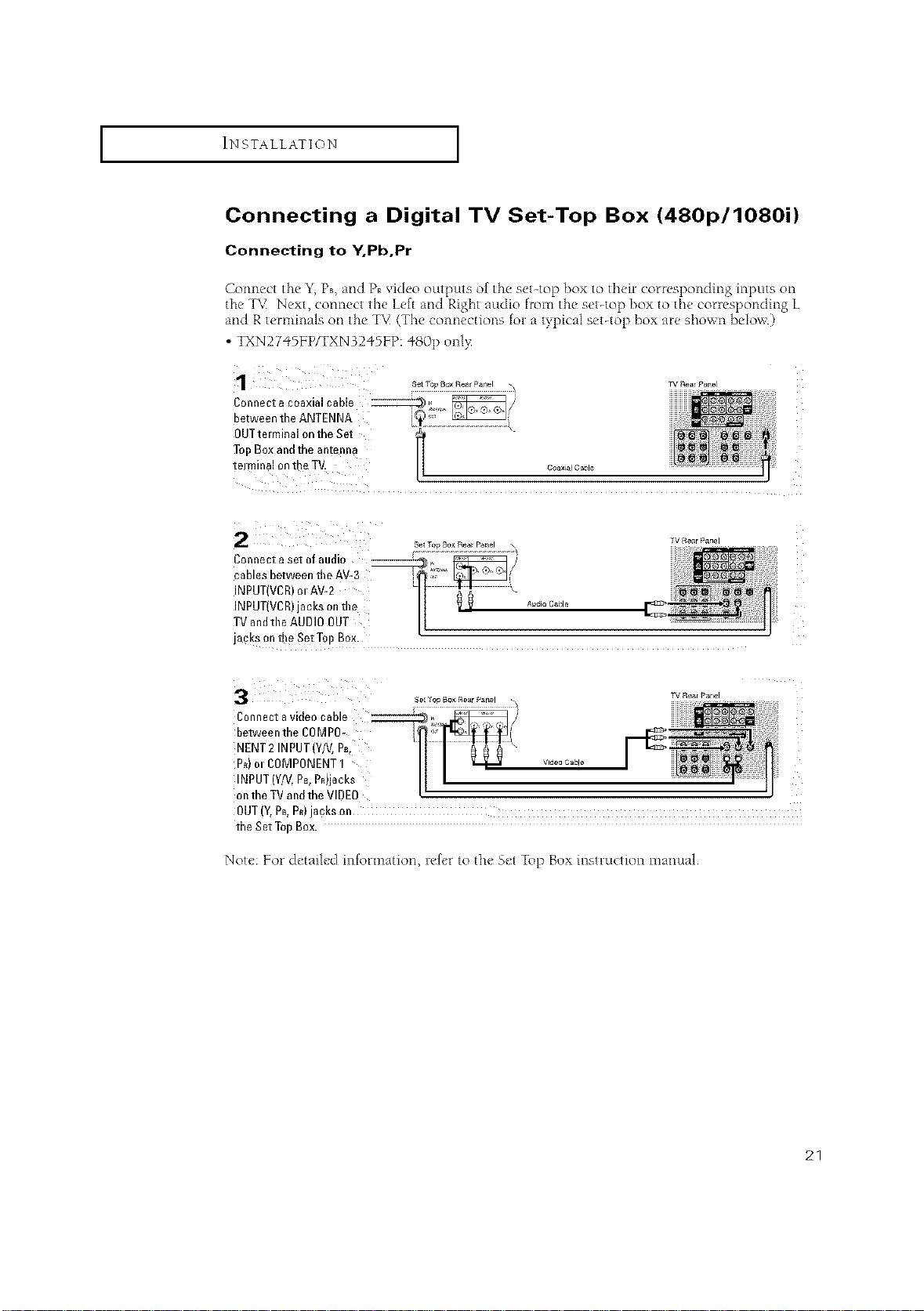
Connecting a Digital TV Set-Top Box (480p/1080i)
Connecting to Y.Pb,Pr
Connect the Y,Ps, and PRvideo outputs of the set-top box to t}_eircorresponding inputs on
the T%1Next, connect the Left and Right audio from the set-top box to the conesponding L
and R terminals on the TV (The connections fol a typical set-top box are shown ]_elow.)
• TXN27"_SFP/TXN3245FP: 480p onl>
¸1¸¸¸¸¸¸¸
OUT terminal on the Set
Top Box and the antenna
tel mina101/the TV. coaxialCaisle
Connectasetofaudio ------_, _ _/_
cables between the AV-3 '_ _i
INPUT(VCR)olAV-2 \
INPUT(VCR)janksonthe _ _ .... _ble
TV andtile AUDI0 OUT
jacks on the Set Top Box.
Connect avideo cable __
between the COMPO-
NENT2 INPUT(Y/V,P_,
P_) m COMPONENT1
INPUT (Y/V,P_,PR)jacks
on the TVand the VIDEO
OUT(Y,PB,P_)jacks on
the Set TopBox.
Note: For detailed information, refer to the Set Top Box instrwction manual
21

I INSTALLATION [
Connecting to DVI (Digital Visual Interface)
(TXN3298HF/TXN3098WHF/TXN2798HF)
B?, inputting a high bandwidth Digital Content Protection high definition picture source
to the DIGITAL INPUT jack on the T\¢ high-definition pictures can be displayed on the
screen in their digital form (This DIGITAL INPUT jack is for use m the future when
High-bandwidth Digital Content Protection DTV decoder, DVD players and D-\q4S are
put on the market.)
C0nnect a coaxial cable _,_ _/}
between the ANTENNA L_;'_
OUTterminal on the Set \
TeI) Box and tbe antenna
terminal on the T_
rv Rear _an_l
Set Ta_ Box RearPanel , TV Rear
Connect aset of audio
cables between the
AUDIO INPUTjacks ontbe
TV andtbe AUDIO OUT
jacks on the Set TopBox.
Connect a DVlcable
between tbe DI61TAL
INPUT jack on the ]'V and
the DVl OUTjack on the
Set TopBox.
No_e
Panel
• The DIGITALINPUT iack can only be use wi_h 1080i and q80p p*cture signals
Set the DTV decoder DIGITALOUTPUT jack output setting to 1080I OR 480P
For detailed info*mation, re,for to the Set Top Box inqructiot_ manual
• The DIGITALINPUT jack is not compatible wi_h the picture signal of a personal computer
• Use a DVI2%pin cane (commercially available) in order to digitally connect _heTV with a
DTVdecoder
22
I INSTALLATION [
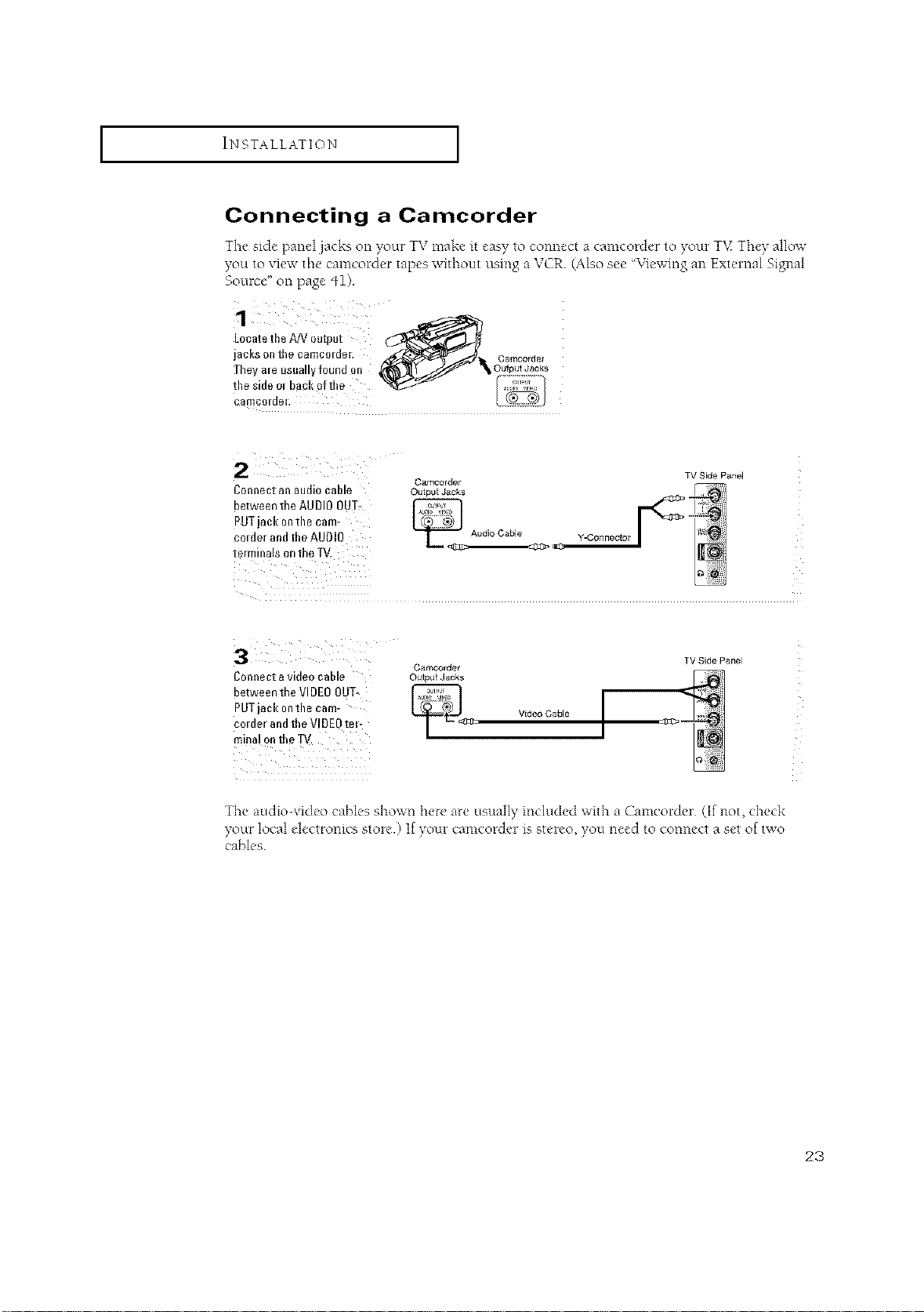
Connecting a Camcorder
The side panel jacks on your TV make it easy to connect a camcorder to your TV They allow
you to xiex_the camcolder tapes without using a VCR. (Also see %qewing an Extelnal Signal
Source" on page 41).
Locate tbe A!V output
jacks ell tbe camcOlder. Camcorde/
Tbey ale usuallyfound on OutputJacks
tbe side o, bad!oftbe
Connect all audio cable Outputj&cks
between the AUDIOOUT,
PUTjack ontile cam-
col der and tbe AUDIO Y-Connector
terminals on the TV.
Connect a videocable
between the VIDEO OUT-
PUTjack ontile cam-
col der and tbeVI DEOtel-
minal ontbe gV.
Camcorder
Camcorder
Outpu Jacks
_,=_ciJ Vide°Cable [
TV Side Panel
TV Sde Panel
The audio-video cables shown here are usually included with a Camcorder (If not, check
yoLirlocal electronics store If your camcorde_ ix stereo you need to connect a set of two
cables
23
INSTALLATION [
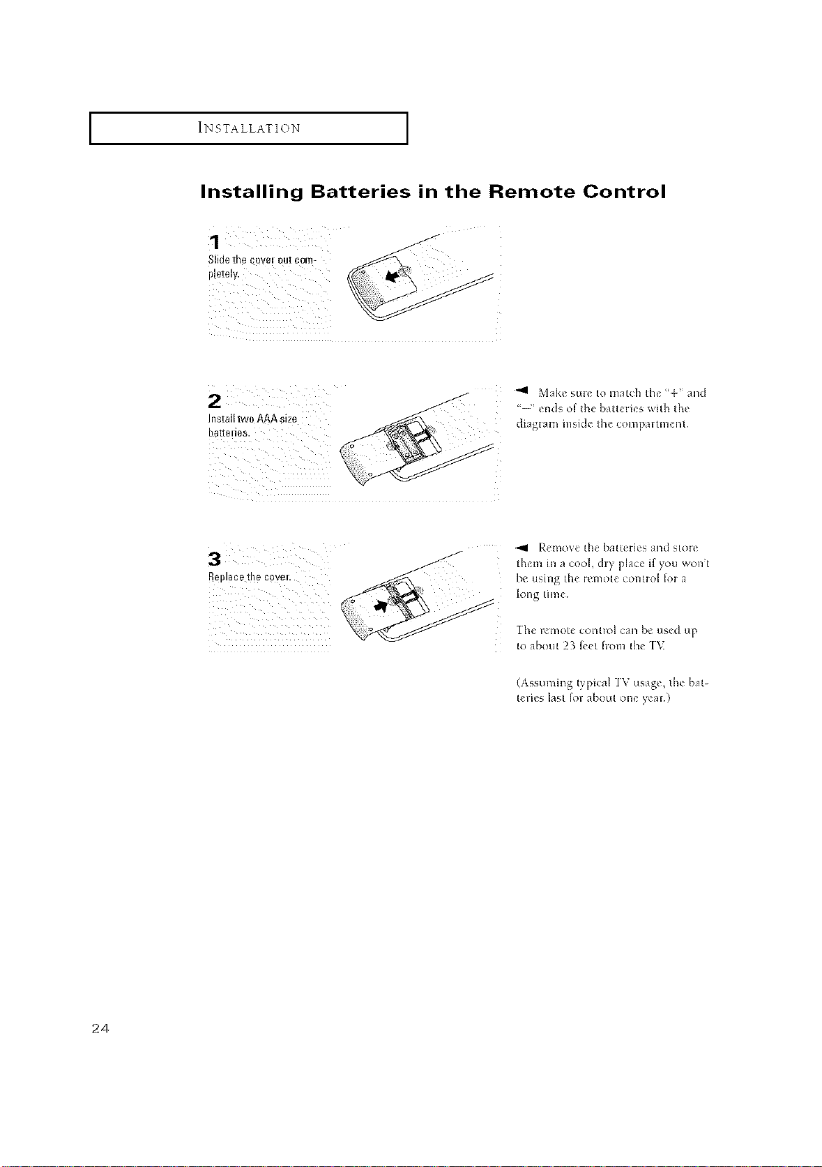
Installing Batteries in the Remote Control
1
II!etely.
Slidethe ¢ovei out ¢om-
2
ba[teiies.
Installtw0AAAsize
Replacetl!e covei.
3
-9 Mak_ stm to match 11_ <%" and
-i', ends of d_e bal[eties wi[h [he
dia_tal_l ill_i_]e [he COll_paltlllent
_91 P.emove the bat[cries and stoic
them in a cool, &y place if you won'[
be using the ienlote connol lot a
long time
_he F_I_IO[CCOI3[FOI Call be used tlp
to about 23 f_et fiom the 1\
(Assuming t pical ]\ usage, the bat-
teiies last for about one year¸¸)
24
OPERATION
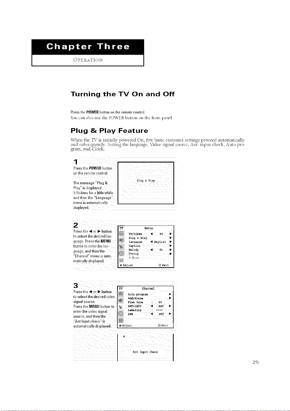
Turning the TV On and Off
P_e_sthePOWERhuron on the lem0te c0ntloL
_bll can also use the p()_EI_ but[on on the fiont panel¸
Plug & Play Feature
Vghe _ le TV s n a y )ower_'d On xe basic customer settings proc_:ed automatically
and subsec[uently: Setting the language, Video signal source, Ant input check, Auto pro-
gram, and Clod{.
1 n
_iii_:{!_i_ xiiii::{i I
The message "Plug&
Pay" s displayed,
It flickers for aIdl]e while
and thenthe 'Language:!
metl_ is automaticaLLy
dSl aye&
Plessthe • or _ bulto
ID sele_'t"thed_sJYed _a_-
guage. Pressthe MENU
button to enter the lan-
guage, and then the
!'Channel" menu is auto-
matically displayed.
3
essm_ • _r I_ buttoa
IO Sele C_ _l'l_ d_Sl|ed Vlfle{
_l_nsi SOUl£e
Press1_eMENU button to
ente/tDe video signal
;OUIC_ ano tiler tne
"Ai/t Ii- _u[ Cll egl( IS
8uionl811o8 v _ISD%8_*_
pl_/ Setllp
n
capt_o_ •
_l_dy 4 o_ •
_ Adjust _]8_xit
_q Chanz_el
AUtO pz_r_
Add/Erase
2_NT/CATV • _T •
L_elin _ ....
LNA • Off •
_ Ad_'ast 1 _x_t
_t _put Check
25