

Samsung TXM 3298HF, TXM 3296HF, TXM 3297HF, TXM 2798HF, TXM 2797HF User Manual
...
Samsung Electronics America inc.
105 Challenger Road, Ridgefield Park, N.J. 07660
SERVICE DIVISION
TEL: 1-800-SAMSUNG (1-800-726-7864)
www.samsungsupport.com
TXM3297HF / TXM3097WHF
TXM2797HF / TXM2796HF
TXM3296HF / TXM3298HF
TXM3098WHF / TXM2798HF
...........................................................................................................................
COLOR TELEVISION
AA68-02395A(ENG)
.............
Owner’s
Instructions
Warning! Important
Safety Instructions
CAUTION: TO REDUCE THE RISK OF ELECTRIC SHOCK, DO NOT
REMOVE COVER (OR BACK). NO USER SERVICEABLE PARTS INSIDE.
REFER SERVICING TO QUALIFIED SERVICE PERSONNEL.
This symbol indicates high voltage is present inside. It is
dangerous to make any kind of contact with any inside part of
this product.
This symbol alerts you that important literature concerning
operation and maintenance has been included with this product.
Note to CATV system installer: This reminder is provided to call CATV system
installer’s attention to Article 820-40 of the National Electrical Code (Section 54 of
Canadian Electrical Code, Part I), that provides guidelines for proper grounding
and, in particular, specifies that the cable ground shall be connected to the
grounding system of the building as close to the point of cable entry as practical.
Caution: FCC/CSA regulations state that any unauthorized changes or modifications to this equipment may void the user’s authority to operate it.
Caution: To prevent electric shock, match the wide blade of plug to the wide slot,
and fully insert the plug.
Attention: pour eviter les chocs electriques, introduire la lame le plus large de la
fiche dans la borne correspondante de la prise et pousser jusqu’au fond.
Important: One Federal Court has held that unauthorized recording of
copyrighted TV programs is an infringement of U.S. copyright laws.
Certain Canadian programs may also be copyrighted and any unauthorized
recording in whole or in part may be in violation of these rights.
To prevent damage which may result in fire or electric shock
hazard, do not expose this appliance to rain or moisture.
CAUTION
RISK OF ELECTRIC SHOCK
DO NOT OPEN
As an ENERGY ST AR Partner ,
Samsung Electronics America, Inc. has determined that this product or product
model meets the ENERGY ST AR guidelines for energy efficiency.

S
AFETY
1
Thank You for Choosing Samsung
Thank you for choosing Samsung! Your new Samsung TV represents the latest in television
technology. We designed it with easy-to-use on-screen menus and closed captioning capabilities, making it one of the best products in its class. We are proud to offer you a product that
will provide convenient, dependable service and enjoyment for years to come.
Important Safety Information
Always be careful when using your TV receiver. To reduce the risk of fire, electrical shock,
and other injuries, keep these safety precautions in mind when installing, using, and
maintaining your machine.
• Read all safety and operating instructions before operating your TV.
• Keep the safety and operating instructions for future reference.
• Heed all warnings on the TV receiver and in the operating instructions.
• Follow all operating and use instructions.
• Unplug the TV receiver from the wall outlet before cleaning. Use a damp cloth; do not use
liquid or aerosol cleaners.
• Never add any attachments and/or equipment without approval of the manufacturer. Such
additions can increase the risk of fire, electric shock, or other personal injury.
• Do not use the TV receiver where contact with or immersion in water is a possibility, such as
near bath tubs, sinks, washing machines, swimming pools, etc.
• Do not place the TV on an unstable cart, stand, tripod, bracket, or
table where it can fall. A falling TV can cause serious injury to a
child or adult, and serious damage to the appliance. Use only with
a cart, stand, tripod, bracket, or table recommended by the manufacturer or sold with the TV. Follow the manufacturer’s instructions when mounting the unit, and use a mounting accessory recommended by the manufacturer. Move the TV and cart with care.
Quick stops, excessive force, and uneven surfaces can make the
unit and cart unsteady and likely to overturn.
• Provide ventilation for the TV receiver. The unit is designed with slots in the cabinet for ventilation to protect it from overheating. Do not block these openings with any object, and do
not place the TV receiver on a bed, sofa, rug, or other similar surface. Do not place it near a
radiator or heat register. If you place the TV receiver on a rack or bookcase, ensure that there
is adequate ventilation and that you’ve followed the manufacturer’s instructions for mounting.
• Operate your TV receiver only from the type of power source indicated on the marking label.
If you are not sure of the type of power supplied to your home, consult your appliance dealer
or local power company.
• Use only a grounded or polarized outlet. For your safety, this TV is equipped with a polarized
alternating current line plug having one blade wider than the other. This plug will fit into the
power outlet only one way. If you are unable to insert the plug fully into the outlet, try
reversing the plug. If the plug still does not fit, contact your electrician to replace your outlet.
2 S
AFETY
• Protect the power cord. Power supply cords should be routed so that they won’t be walked
on or pinched by objects placed on or against them. Pay particular attention to cords at
plugs, convenience receptacles, and the point where they exit from the unit.
• Unplug the TV from the wall outlet and disconnect the antenna or cable system during a
lightning storm or when left unattended and unused for long periods of time. This will prevent damage to the unit due to lightning and power-line surges.
• Avoid overhead power lines. An outside antenna system should not be placed in the vicinity
of overhead power lines or other electric light or power circuits or where it can fall into such
power lines or circuits. When installing an outside antenna system, be extremely careful to
keep from touching the power lines or circuits. Contact with such lines can be fatal.
• Do not overload the wall outlet or extension cords. Overloading can result in fire or electric
shock.
• Do not insert anything through the openings in the unit, where they can touch dangerous
voltage points or damage parts. Never spill liquid of any kind on the TV.
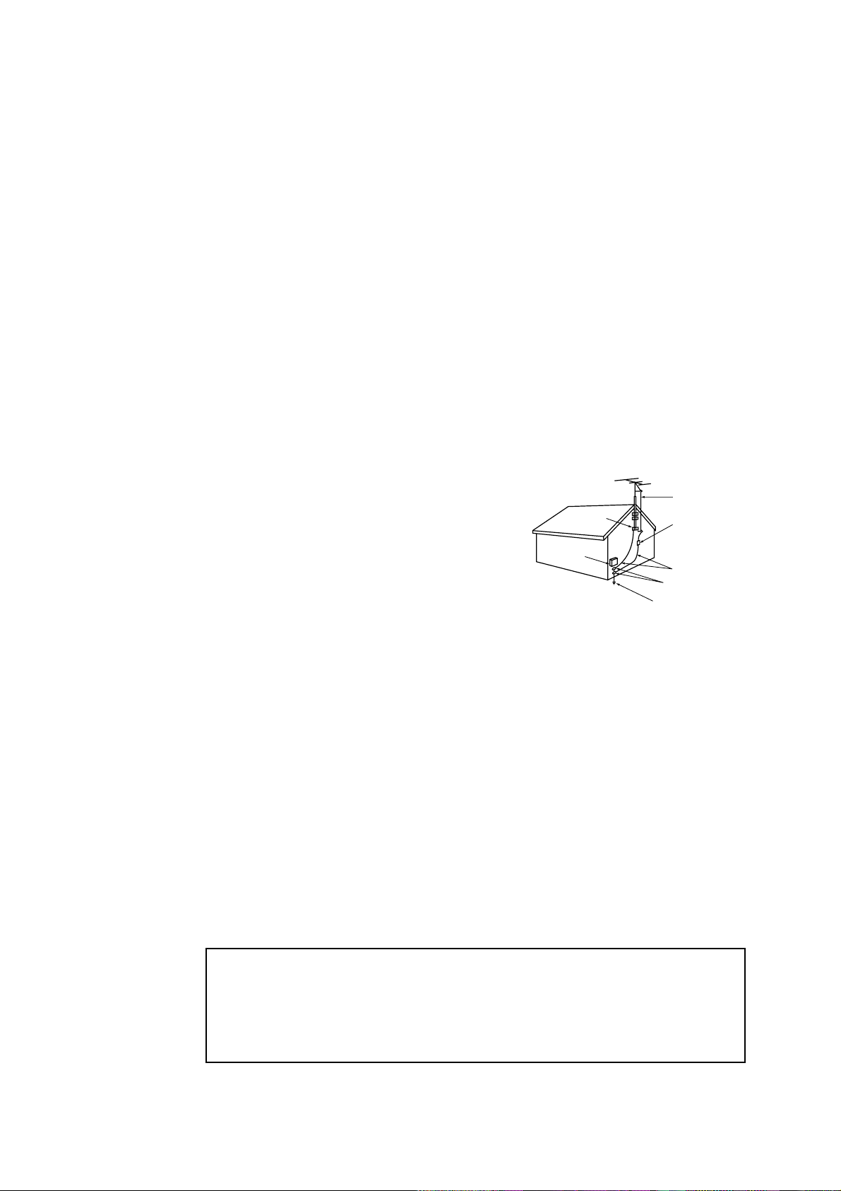
• Ground outdoor antennas. If an outside antenna or
cable system is connected to the TV, be sure the
antenna or cable system is grounded so as to provide
some protection against voltage surges and built-up
static charges. Section 810 of the National Electrical
Code, ANSI/NFPA No.70-1984, provides information
about proper grounding of the mast and supporting
structure, grounding of the lead-in wire to an antenna
discharge unit, size of grounding conductors, location
of antenna discharge unit, connection to grounding
electrodes, and requirements for the grounding electrode.
• Do not attempt to service the TV yourself. Refer all servicing to qualified service personnel.
Unplug the unit from the wall outlet and refer servicing to qualified service personnel under
the following conditions:
- when the power-supply cord or plug is damaged
- if liquid has been spilled on the unit or if objects have fallen into the unit
- if the TV has been exposed to rain or water
- if the TV does not operate normally by following the operating instructions
- if the TV has been dropped or the cabinet has been damaged
- when the TV exhibits a distinct change in performance
• If you make adjustments yourself, adjust only those controls that are covered by the operat-
ing instructions. Adjusting other controls may result in damage and will often require extensive work by a qualified technician to restore the TV to normal.
• When replacement parts are required, be sure the service technician uses replacement parts
specified by the manufacturer or those that have the same characteristics as the original part.
Unauthorized substitutions may result in additional damage to the unit.
• Upon completion of any service or repairs to this TV, ask the service technician to
perform safety checks to determine that the TV is in a safe operating condition.
This device complies with part 15 of the FCC Rules. Operation is subject to the
following two conditions:
(1) This device may not cause harmful interference, and
(2) This device must accept any interference that may cause undesired operation.
This television receiver provides display of television closed captioning in accordance
with §15.119 of the FCC rules.
EXAMPLE OF
ANTENNA GROUNDING
GROUND CLAMP
ELECTRIC
SERVICE
EQUIPMENT
NEC — NATIONAL ELECTRICAL CODE
GROUND CLAMPS
POWER SERVICE GROUNDING
ELECTRODE SYSTEM
(NEC ART 250, PART H)
ANTENNA
LEAD IN WIRE
ANTENNA
DISCHARGE UNIT
(NEC SECTION 810-20)
GROUNDING
CONDUCTORS
(NEC SECTION 810-21)

S
AFETY
3
1) Read these instructions.
2) Keep these instructions.
3) Heed all warnings.
4) Follow all instructions.
5) Do not use this apparatus near water.
6) Clean only with dry cloth.
7) Do not block any ventilation openings, Install in accordance with the manufacturer’s
instructions.
8) Do not install near any heat sources such as radiators, heat registers, or other apparatus
(including amplifiers) that produce heat.
9) Do not defeat the safety purpose of the polarized or grounding-type plug. A polarized
plug has two blades with one wider than the other. A grounding type plug has two blades
and a third grounding prong. The wide blade or the third prong are provided for your
safety. If the provided plug does not fit into your outlet, consult an electrician for replacement of the obsolete outlet.
10) Protect the power cord from being from being walked on or pinched particularly at plugs,
convenience receptacles, and the point where they exit from the apparatus.
11) Only use attachments/accessories specified by the manufacturer.
12) Use only with cart, stand, tripod, bracket, or table specified by the manufacturer, or sold
with the apparatus. When a used, caution when moving the cart/apparatus combination to
avoid injury from tip-over.
13) Unplug this apparatus. When a cart is used, use caution when moving the cart/apparatus
combination to avoid injury from tip-over.
14) Refer all servicing to qualified service personnel. Servicing is required when the apparatus
has been damaged in any way, such as power-supply cord or plug is damaged, liquid has
been spilled or objects have fallen into the apparatus, the apparatus has been exposed to
rain or moisture, does not operate normally, or has been dropped.
DOUBLE INSULATED - When servicing
use only identical replacement parts.

CONTENTS
C
ONTENTS
1
Chapter 1: Your New TV . . . . . . . . . . . . . . .1.1
List of Features. . . . . . . . . . . . . . . . . . . . . . . . . . . . . . . . . . . . . . . . . 1.1
Familiarizing Yourself with The TV. . . . . . . . . . . . . . . . . . . . . . . . . . 1.2
Front Panel Buttons . . . . . . . . . . . . . . . . . . . . . . . . . . . . . . 1.2
Front Panel Jacks . . . . . . . . . . . . . . . . . . . . . . . . . . . . . . . . 1.3
Rear Panel Jacks . . . . . . . . . . . . . . . . . . . . . . . . . . . . . . . . . 1.4
Remote Control . . . . . . . . . . . . . . . . . . . . . . . . . . . . . . . . . 1.5
Chapter 2: Installation . . . . . . . . . . . . . . . . 2.1
Connecting VHF and UHF Antennas . . . . . . . . . . . . . . . . . . . . . . . . 2.1
Antennas with 300-ohm Flat Twin Leads . . . . . . . . . . . . . . 2.1
Antennas with 75-ohm Round Leads . . . . . . . . . . . . . . . . . 2.2
Separate VHF and UHF Antennas. . . . . . . . . . . . . . . . . . . . 2.2
Connecting Cable TV . . . . . . . . . . . . . . . . . . . . . . . . . . . . . . . . . . . . 2.2
Cable without a Cable Box. . . . . . . . . . . . . . . . . . . . . . . . . 2.2
Connecting to a Cable Box that Descrambles
All Channels. . . . . . . . . . . . . . . . . . . . . . . . . . . . . . . . . . . . 2.3
Connecting to a Cable Box that Descrambles
some Channels. . . . . . . . . . . . . . . . . . . . . . . . . . . . . . . . . . 2.3
Connecting a VCR . . . . . . . . . . . . . . . . . . . . . . . . . . . . . . . . . . . . . . 2.4
Connecting an S-VHS VCR. . . . . . . . . . . . . . . . . . . . . . . . . 2.6
Connecting a Second VCR to Record from the TV . . . . . . . 2.7
Connecting a DVD Player. . . . . . . . . . . . . . . . . . . . . . . . . . . . . . . . . 2.7
Connecting a Camcorder . . . . . . . . . . . . . . . . . . . . . . . . . . . . . . . . . 2.8
Installing Batteries in the Remote Control. . . . . . . . . . . . . . . . . . . . . 2.9
Chapter 3: Operation. . . . . . . . . . . . . . . . . . 3.1
Turning the TV On and Off. . . . . . . . . . . . . . . . . . . . . . . . . . . . . . . . 3.1
Plug & Play Feature . . . . . . . . . . . . . . . . . . . . . . . . . . . . . . . . . . . . . 3.1
Viewing the Menus and On-Screen Displays. . . . . . . . . . . . . . . . . . . 3.3
Viewing the Menus. . . . . . . . . . . . . . . . . . . . . . . . . . . . . . . 3.3
Viewing the Display . . . . . . . . . . . . . . . . . . . . . . . . . . . . . . 3.3
Selecting a Menu Language. . . . . . . . . . . . . . . . . . . . . . . . . . . . . . . . 3.4
Memorizing the Channels. . . . . . . . . . . . . . . . . . . . . . . . . . . . . . . . . 3.5
Selecting the Video Signal-source. . . . . . . . . . . . . . . . . . . . 3.5
Storing Channels in Memory (Automatic Method). . . . . . . 3.6
Adding and Erasing Channels (Manual Method) . . . . . . . . 3.7
Changing Channels . . . . . . . . . . . . . . . . . . . . . . . . . . . . . . . . . . . . . 3.8
Using the Channel Buttons. . . . . . . . . . . . . . . . . . . . . . . . . 3.8
Directly Accessing Channels. . . . . . . . . . . . . . . . . . . . . . . . 3.8
Using the PRE-CH Button to select the Previous Channel. . 3.8
Adjusting the Volume. . . . . . . . . . . . . . . . . . . . . . . . . . . . . . . . . . . . 3.8
Using Mute. . . . . . . . . . . . . . . . . . . . . . . . . . . . . . . . . . . . . 3.8
Labeling the Channels . . . . . . . . . . . . . . . . . . . . . . . . . . . . . . . . . . . 3.9
Setting the Clock . . . . . . . . . . . . . . . . . . . . . . . . . . . . . . . . . . . . . . . 3.10
Option 1: Setting the Clock Manually . . . . . . . . . . . . . . . . 3.10
Option 2: Using the Local PBS Channel to
Automatically Set the TV Clock . . . . . . . . . . . . . . . . . . . . . 3.11
Customizing the Picture . . . . . . . . . . . . . . . . . . . . . . . . . . . . . . . . . . 3.13
Using Automatic Picture Settings . . . . . . . . . . . . . . . . . . . . . . . . . . . 3.14
Customizing the Sound . . . . . . . . . . . . . . . . . . . . . . . . . . . . . . . . . . 3.15
Using Automatic Sound Settings. . . . . . . . . . . . . . . . . . . . . . . . . . . . 3.16
Setting The On/Off Melody. . . . . . . . . . . . . . . . . . . . . . . . . . . . . . . . 3.17
Viewing a VCR or Camcorder Tape. . . . . . . . . . . . . . . . . . . . . . . . . . 3.18

2 CONTENTS
CONTENTS
Chapter 4: Special Features . . . . . . . . . . . . 4.1
Customizing Your Remote Control . . . . . . . . . . . . . . . . . . . . . . . . . . 4.1
Setting Up Your Remote Control to Operate Your VCR. . . . 4.1
Setting Up Your Remote Control to
Operate Your Cable Box . . . . . . . . . . . . . . . . . . . . . . . . . . . 4.3
Fine Tuning Channels. . . . . . . . . . . . . . . . . . . . . . . . . . . . . 4.4
Digital Noise Reduction . . . . . . . . . . . . . . . . . . . . . . . . . . . . . . . . . . 4.5
Changing the Screen Size . . . . . . . . . . . . . . . . . . . . . . . . . . . . . . . . . 4.6
Using the R.Surf . . . . . . . . . . . . . . . . . . . . . . . . . . . . . . . . . . . . . . . . 4.7
Setting the On/Off Timer . . . . . . . . . . . . . . . . . . . . . . . . . . . . . . . . . 4.8
Setting the Sleep Timer. . . . . . . . . . . . . . . . . . . . . . . . . . . . . . . . . . . 4.9
Sound Features. . . . . . . . . . . . . . . . . . . . . . . . . . . . . . . . . . . . . . . . . 4.10
Choosing a Multi-Channel Sound (MTS) Soundtrack. . . . . 4.10
Extra sound settings
(Turbo Sound, Surround, or Auto Volume) . . . . . . . . . . . . 4.11
Viewing Closed Captions . . . . . . . . . . . . . . . . . . . . . . . . . . . . . . . . . 4.12
Viewing Picture-in-Picture . . . . . . . . . . . . . . . . . . . . . . . . . . . . . . . . 4.13
Activation Picture-in-Picture . . . . . . . . . . . . . . . . . . . . . . . 4.13
Selecting a Signal Source (External A/V) for PIP . . . . . . . . . 4.13
Changing the Size of the PIP Window . . . . . . . . . . . . . . . . 4.13
Changing the Location (Rotating) the PIP Window . . . . . . 4.14
Swapping the Contents of the PIP image and Main image . 4.14
Changing the PIP Channel . . . . . . . . . . . . . . . . . . . . . . . . . 4.14
Using the V-Chip (Option) . . . . . . . . . . . . . . . . . . . . . . . . . . . . . . . . 4.15
Setting Up Your Personal ID Number (PIN) . . . . . . . . . . . . 4.15
How to Enable/Disable the V-Chip. . . . . . . . . . . . . . . . . . . 4.16
How to Set up Restrictions Using the “TV guidelines” . . . . 4.16
How to Set up Restrictions using the MPAA Ratings:
G, PG, PG-13, R, NC-17, X . . . . . . . . . . . . . . . . . . . . . . . . 4.18
How to Reset the TV after the V-Chip Blocks
a Channel (“Emergency Escape”) . . . . . . . . . . . . . . . . . . . . 4.19
Chapter 5: Troubleshooting . . . . . . . . . . . . 5.1
Identifying Problems . . . . . . . . . . . . . . . . . . . . . . . . . . . . . . . . . . . . 5.1
Appendix . . . . . . . . . . . . . . . . . . . . . . . . . . . A.1
Cleaning and Maintaining Your TV. . . . . . . . . . . . . . . . . . . . . . . . . . A.1
Using Your TV in Another Country . . . . . . . . . . . . . . . . . . . . . . . . . A.1
Specifications . . . . . . . . . . . . . . . . . . . . . . . . . . . . . . . . . . . . . . . . . . A.1

1.1 CHAPTER ONE: YOUR NEWTV
List of Features
Your TV was designed with the latest technology. This TV is a high-performance unit that
includes the following special features:
• Full Flat Screen
• Easy-to-use remote control
• Easy-to-use on-screen menu system
• Automatic timer to turn the TV on and off
• Adjustable picture and sound settings that can be stored in the TV’s memory
• Automatic channel tuning for up to 181 channels
• A special filter to reduce or eliminate reception problems
• Fine tuning control for the sharpest picture possible
• A built-in multi-channel sound decoder for stereo and bilingual listening
• Built-in, dual channel speakers
• A special sleep timer
• Headphone jack for private listening
• 16:9 letter box format available depending upon source
• Picture in Picture
Chapter One
YOUR NEW TV
CHAPTER ONE: YOUR NEW TV 1.2
Familiarizing Yourself with The TV
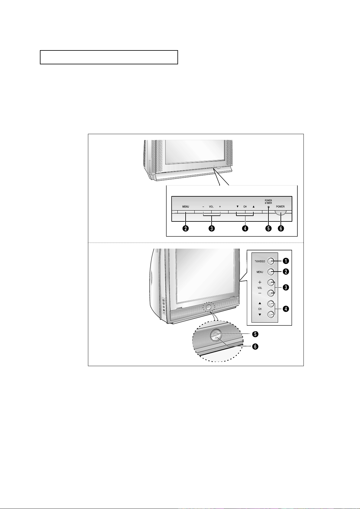
Front Panel Buttons
The buttons on the front panel control your TV’s basic features, including the on-screen
menu. To use the more advanced features, you must use the remote control.
YOUR NEW TV
Œ
TV/VIDEO
(TXM3298HF/TXM3098WHF/
TXM2798HF)
Press to change between viewing TV programs
and signals from other components.
´
MENU
Press to see an on-screen menu of your TV's
features.
ˇ
VOL – , +
Press to increase or decrease the
volume. Also used to select items on the onmscreen menu.
¨
CH ▼ and CH ▲
Press to change channels. Also press to highlight various items on the on-screen menu.
ˆ
POWER & TIMER indicator
Lights up when you turn the power off.
Ø
POWER
Press to turn the TV on and off.
• TXM3297HF
• TXM3097WHF
• TXM2797HF
• TXM2796HF
• TXM3296HF
• TXM3298HF
• TXM3098WHF
• TXM2798HF
1.3 CHAPTER ONE: YOUR NEWTV
YOUR NEW TV
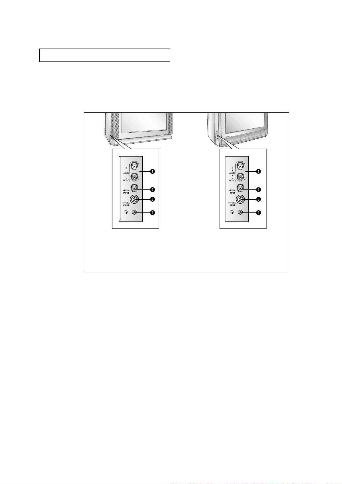
Front Panel Jacks
You can use the front panel jacks to connect an A/V component that is used only occasionally, such as a camcorder or video game. (For information on connecting equipment,
see pages 2.1 – 2.8.)
Œ
AUDIO INPUT jacks
Used to connect the audio signals from a camcorder or video game.
´
VIDEO INPUT jack
Used to connect a video signal from a camcorder or video game.
ˇ
SUPER VIDEO INPUT jack
S-Video signal from an S-VHS VCR or DVD
player.
¨
HEADPHONE jack
Connect a set of external headphones to this
jack for private listening.
• TXM3297HF
• TXM3097WHF
• TXM2797HF
• TXM2796HF
• TXM3296HF
• TXM3298HF
• TXM3098WHF
• TXM2798HF
CHAPTER ONE: YOUR NEW TV 1.4
YOUR NEW TV
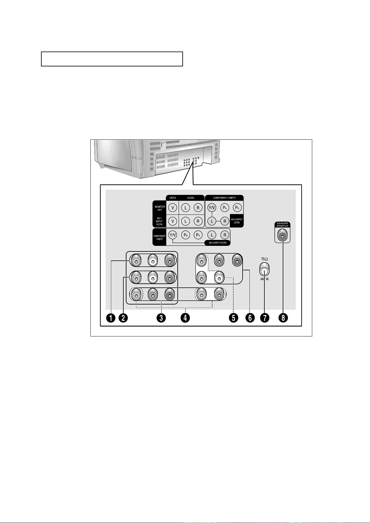
Rear Panel Jacks
Use the rear panel jacks to connect an A/V component that will be connected
continuously, such as a VCR or a DVD player.
Because there are two sets of input jacks, you can connect two different A/V
components (i.e., a VCR and a DVD, 2 VCRs, etc.)
For more information on connecting equipment, see pages 2.1 – 2.8.
Œ
AUDIO-VIDEO MONITOR
OUTPUT jacks
Connect to the audio/video input jacks of a
recording VCR.
Note: The Monitor Out does not operate in
Component 1 or 2 modes.
´,¨,ˆ
VIDEO INPUT jack
Video and Audio signals from VCRs, DVD players
and similar devices.
Note: The common jack of component 1 and
AV2, component 2 and AV3 input jacks are
exclusive relation with each other.
ˇ
COMPONENT 1 INPUT jacks
(480i/480p/1080i)
Connect to the audio and component output
jacks of a DVD player or Set-Top Box.
Note: Only black and white signals are output
from a monitor in DVD/DTV mode.
Ø
COMPONENT 2 INPUT jacks
(480i/480p/1080i)
Connect to the audio and component output
jacks of a DVD player or Set-Top Box.
Note: Only black and white signals are output
from a monitor in DVD/DTV mode.
∏
VHF/UHF
Connect to an antenna or to a cable TV system.
”
SUB-WOOFER SPEAKER
OUT
(TXM3298HF/TXM3098WHF /
TXM2798HF)
Connect to the Sub-woofer speaker jack (built in
Sub-woofer cable).
1.5 CHAPTER ONE: YOUR NEWTV
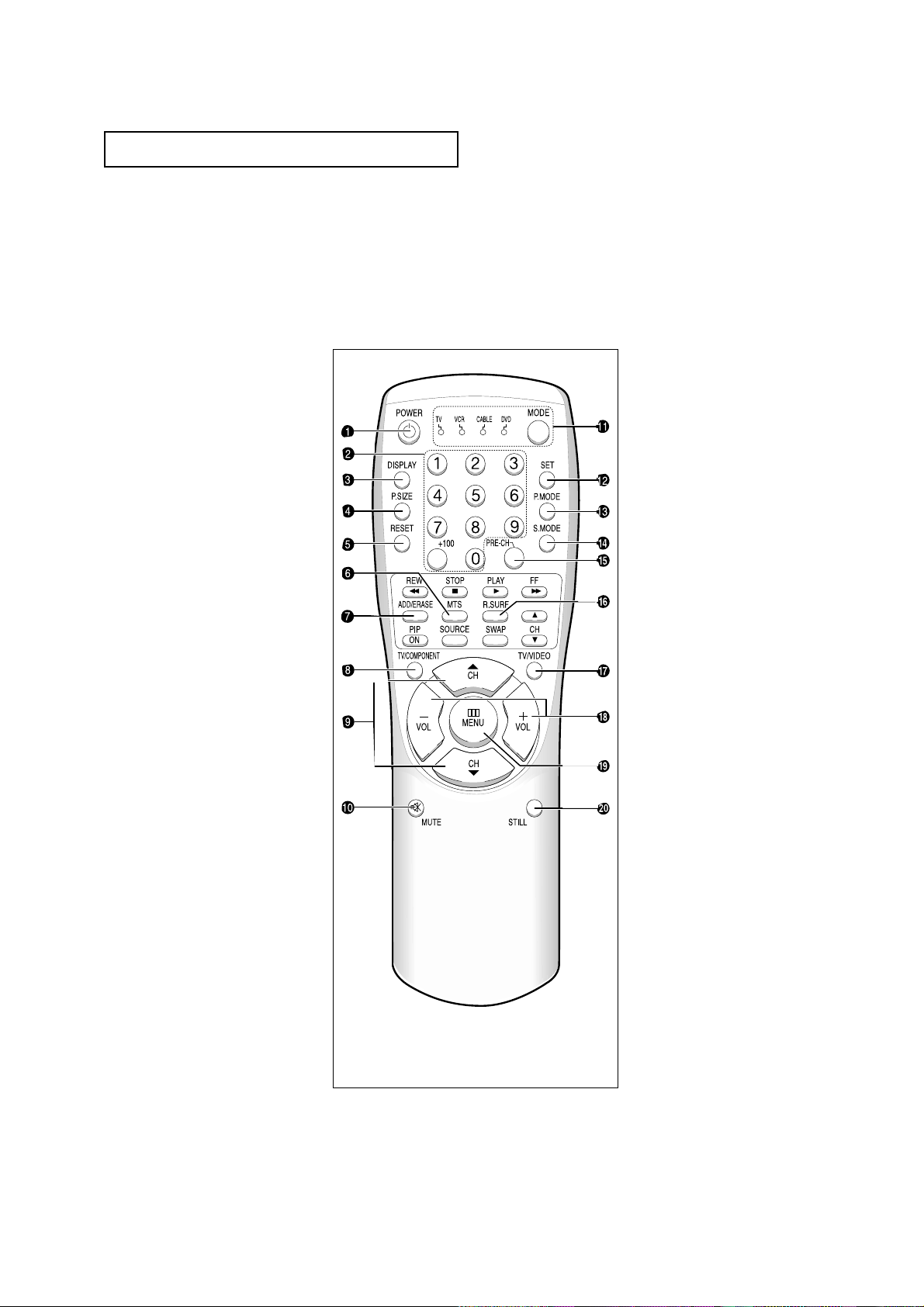
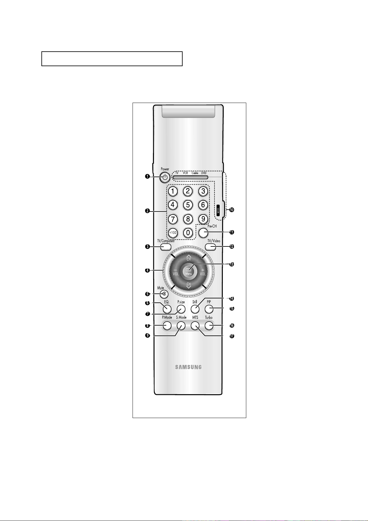
Remote Control
You can use the remote control up to about 23 feet from the TV. When using the remote,
always point it directly at the TV.
You can also use your remote control to operate your VCR and cable box. See page 4.1
for details.
Œ
POWER
Turns the TV on and off.
´
Number buttons
Press to select channels directly
on the TV.
+100
Press to select channels over 100.
For example, to select
channel 121, press “+100,” then
press “2” and “1.”
ˇ
DISPLAY
Press to see the time, channel,
etc., on-screen. Also press to exit
(quit) the menu system.
¨
P.SIZE
Press to change the screen size.
Your choices are Normal screen,
Zoom screen or Wide screen.
ˆ
RESET
If your remote control is not functioning properly, take out the batteries and press the reset button
for about 2~3 seconds. Re-insert
the batteries and try using the
remote control again.
Ø
MTS (Multichannel
Television Stereo)
Press to choose stereo, mono or
Separate Audio Program (SAP
broadcast).
∏
ADD/ERASE
Press to add or erase channels in
the TV’s memory.
”
TV/COMPONENT
Press to switch the TV or COMPONENT mode.
’
CH▲ and CH▼
(Channel Up/Down)
Press CH▲ or CH▼to change
channels. (Also used to highlight
selections on the on-screen
menus.)
˝
MUTE
Press to temporarily cut off
the sound.
Ô
MODE
Selects a target device to be controlled by the Samsung remote
control (i.e., TV, VCR, Cable box, or
DVD).
SET
Use this button when you are setting up your remote control to
operate your VCR, Cable box, or
DVD).
Ò
P.MODE
Adjust the TV picture by selecting
one of the preset factory settings
(or select your personal, customized picture settings).
Ú
S.MODE
Adjust the TV sound by selecting
one of the preset factory settings
(or select your personal, customized sound settings).
Æ
PRE-CH
Tunes to the previous channel.
ı
R.SURF
Press the R.SURF button to automatically return to a preferred
channel after a user-preset time
delay.
˜
TV/VIDEO
Press to display all of the
available video sources (i.e.,
Antenna/cable, VCR).
¯
VOL -, VOL +
Press to increase or decrease the
volume. (Also used to make selections on the on-screen menus.)
˘
MENU
Displays the main on-screen
menu.
¿
STILL(Main)
Press to stop the action during a
particular scene. Press again to
resume normal video.
YOUR NEW TV
TXM3297HF / TXM3097WHF
TXM2797HF / TXM2796HF
TXM3296HF
CHAPTER ONE: YOUR NEW TV 1.6
YOUR NEW TV
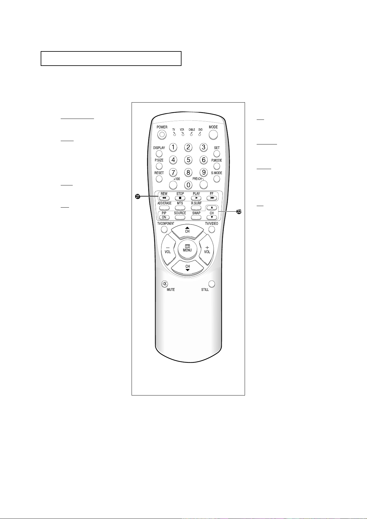
Remote Control
¸
VCR Controls
REW (Rewind)
Press to rewind a tape in your
VCR.
STOP
Press this button to stop a tape
during play, record, rewind or
fast forward. If the button is
pressed during Full-Automatic
play, the function will be cancelled.
PLAY
Press the PLAY button to play
back prerecorded tapes.
F. F
Press to fast forward the tape in
your VCR.
˛
PIP Controls
PIP
Press this button to control the PIP
window.
SOURCE
Press to select one of the available
signal sources for the PIP window.
SWAP
Exchanges the video signal that is
currently displayed on the main
screen with the signal in the PIP
window.
CH
Displays the available channels in
sequence. (These buttons change
channels in the PIP window only).
TXM3297HF / TXM3097WHF
TXM2797HF / TXM2796HF
TXM3296HF
1.7 CHAPTER ONE: YOUR NEWTV
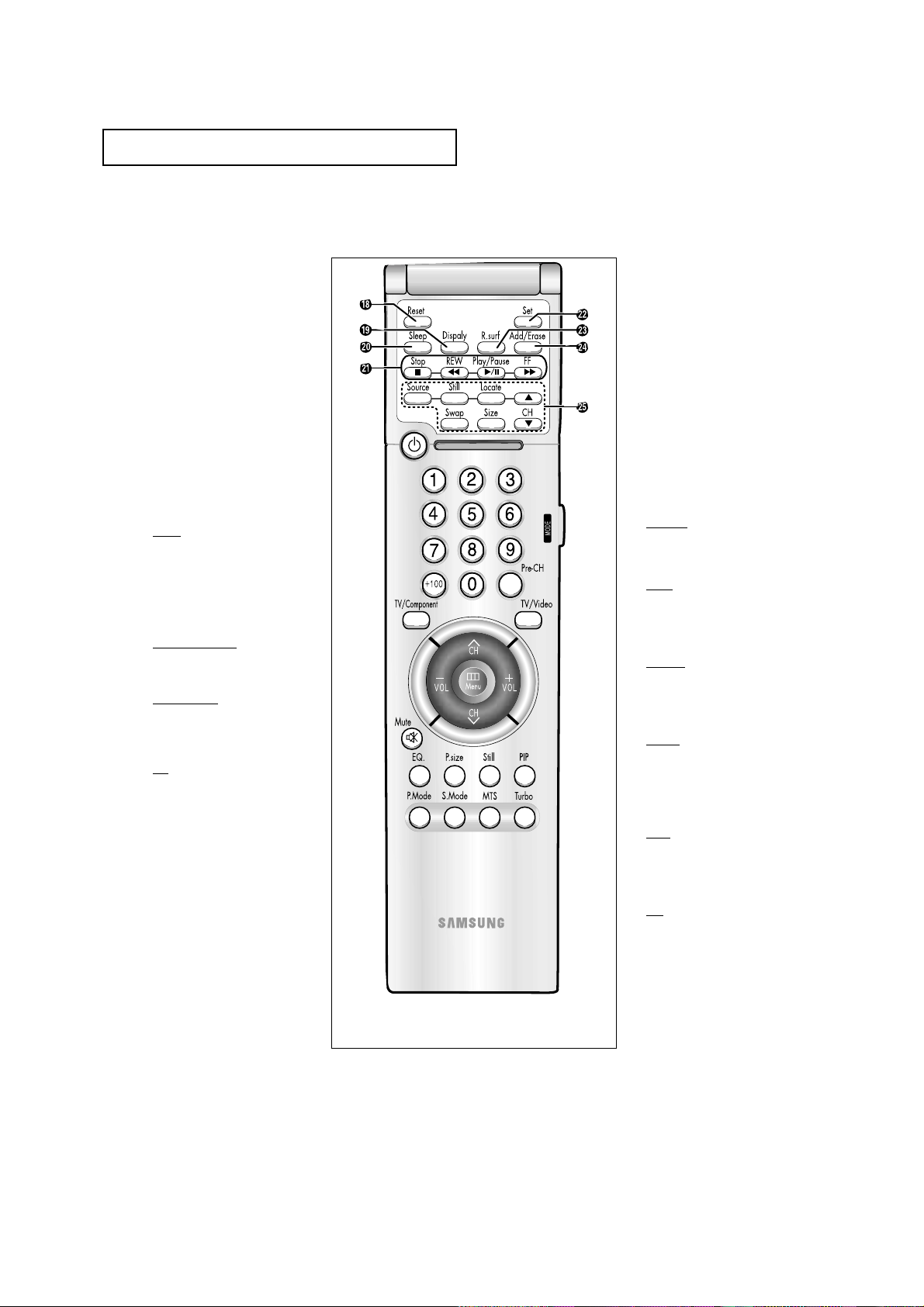
Remote Control
Œ
Power
Turns the TV on and off.
´
Number buttons
Press to select channels directly
on the TV.
+100
Press to select channels over 100.
For example, to select
channel 121, press “+100,” then
press “2” and “1.”
ˇ
TV/Component
Press to switch the TV or COMPONENT mode.
¨
CH▲ and CH▼
(Channel Up/Down)
Press CH▲ or CH▼to change
channels. (Also used to highlight
selections on the on-screen
menus.)
VOL -, VOL +
Press to increase or decrease the
volume. (Also used to make selections on the on-screen menus.)
ˆ
Mute
Press to temporarily cut off
the sound.
Ø
EQ.
Press to select Equalizer menu
directly.
∏
P.size
Press to change the screen size.
Your choices are Normal screen,
Zoom screen or Wide screen.
”
P.Mode
Adjust the TV picture by selecting
one of the preset factory settings
(or select your personal, customized picture settings).
’
S.Mode
Adjust the TV sound by selecting
one of the preset factory settings
(or select your personal, customized sound settings).
˝
MODE
Selects a target device to be controlled by the Samsung remote
control (i.e., TV, VCR, Cable box, or
DVD).
Ô
Pre-CH
Tunes to the previous channel.
TV/Video
Press to display all of the
available video sources (i.e.,
Antenna/cable, VCR).
Ò
Menu
Displays the main on-screen
menu.
Ú
Still(Main)
Press to stop the action during a
particular scene. Press again to
resume normal video.
Æ
PIP
Press this button to control the PIP
window.
ı
Turbo
Turbo sound emphasizes the bass
and treble frequencies to add fullness to the sound.
˜
MTS (Multichannel
Television Stereo)
Press to choose stereo, mono or
Separate Audio Program (SAP
broadcast).
TXM3298HF / TXM3098WHF
TXM2798HF
YOUR NEW TV
CHAPTER ONE: YOUR NEW TV 1.8
YOUR NEW TV
Remote Control
¯
Reset
If your remote control is not functioning properly, take out the batteries and press the reset button
for about 2~3 seconds. Re-insert
the batteries and try using the
remote control again.
˘
Display
Press to see the time, channel,
etc., on-screen. Also press to exit
(quit) the menu system.
¿
Sleep
Press to select a preset time interval for automatic shutoff.
¸
VCR Controls
Stop
Press this button to stop a tape
during play, record, rewind or
fast forward. If the button is
pressed during Full-Automatic
play, the function will be cancelled.
REW (Rewind)
Press to rewind a tape in your
VCR.
Play/Pause
Press the Play/Pausebutton to
play back prerecorded tapes or
pause the tape.
FF
Press to fast forward the tape in
your VCR.
˛
Set
Use this button when you are setting up your remote control to
operate your VCR, Cable box, or
DVD).
◊
R.surf
Press the R.SURF button to automatically return to a preferred
channel after a user-preset time
delay.
±
Add/Erase
Press to add or erase channels in
the TV’s memory.
≠
PIP Controls
Source
Press to select one of the available
signal sources for the PIP window.
Still
Press to stop the action during a
particular scene. Press again to
resume normal video.
Locate
Press to move the PIP window to
any of the four corners of the TV
screen.
S
wap
Exchanges the video signal that is
currently displayed on the main
screen with the signal in the PIP
window.
Size
Press to make the PIP window
small, large, double screen or
stock ticker window.
CH
Displays the available channels in
sequence. (These buttons change
channels in the PIP window only).
TXM3298HF / TXM3098WHF
TXM2798HF
2.1 CHAPTER TWO: INSTALLATION
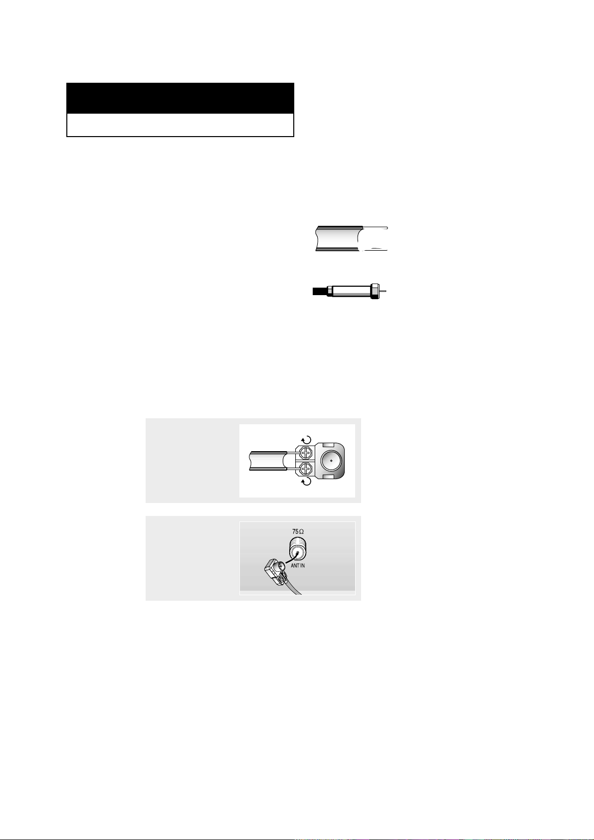
Connecting VHF and UHF Antennas
If your antenna has a set of leads that
look like this, see “Antennas with
300-ohm Flat Twin Leads,” below.
If your antenna has one lead that looks
like this, see “Antennas with 75-ohm
Round Leads,” on page 2.2.
If you have two antennas, see “Separate
VHF and UHF Antennas,” on page 2.2.
Antennas with 300-ohm Flat Twin Leads
If you are using an off-air antenna (such as a roof antenna or “rabbit ears”) that has
300-ohm twin flat leads, follow the directions below.
Chapter Two
INSTALLATION
1
Place the wires from the
twin leads under the
screws on the 300-75 ohm
adaptor (not supplied).
Use a screwdriver to
tighten the screws.
2
Plug the adaptor into the
VHF/UHF terminal on the
bottom of the back panel.
2
CHAPTER TWO: INSTALLATION 2.2
Connecting Cable TV
To connect to a cable TV system, follow the instructions below.
Cable without a Cable Box
▼
1
Plug the incoming cable
into the VHF/UHF
antenna terminal on back
of the TV.
Because this TV is
cable-ready, you do not need a
cable box to view unscrambled cable
channels.
2
Plug the combiner
into the VHF/UHF terminal on the bottom
of the rear panel.
INSTALLATION
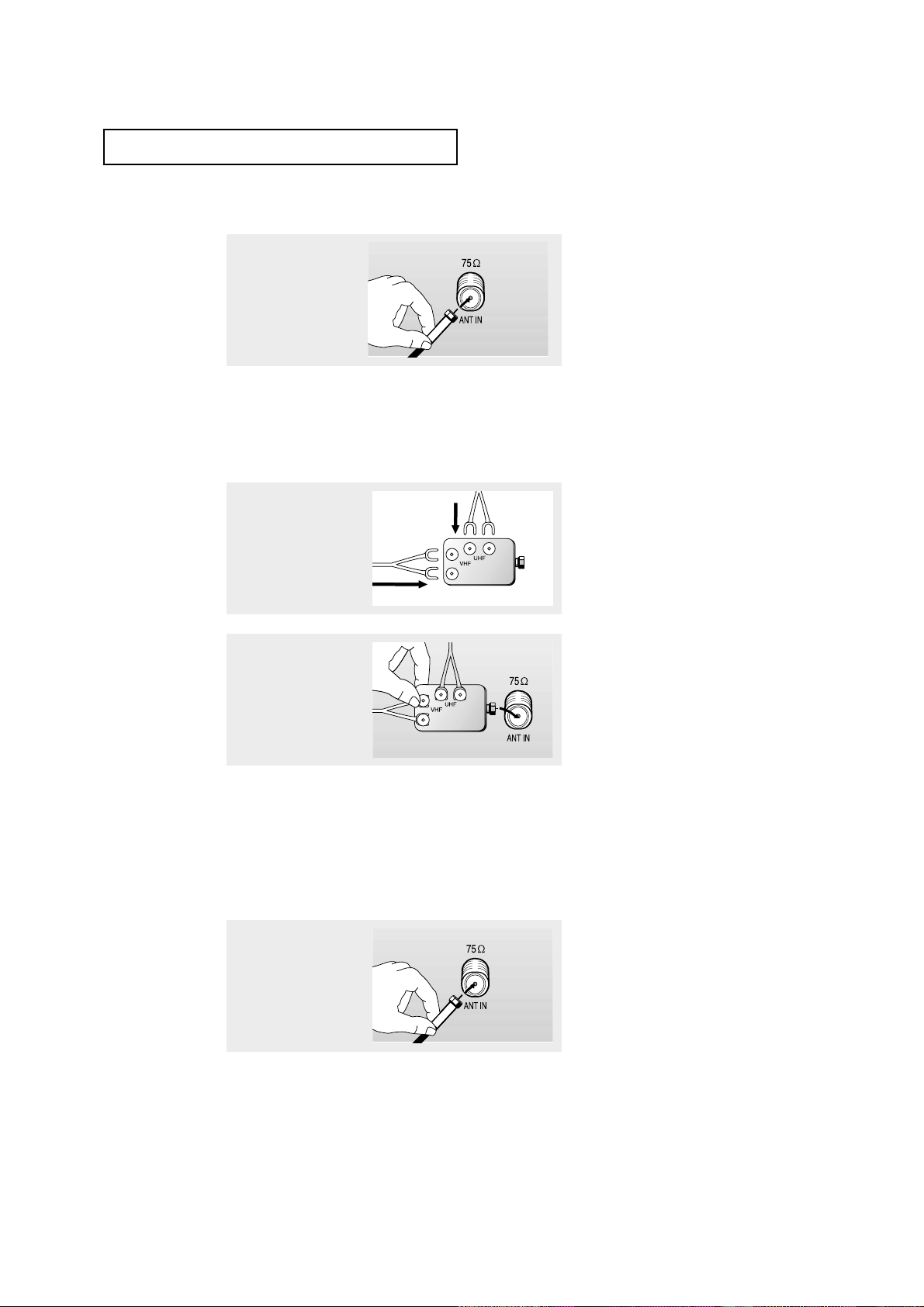
Separate VHF and UHF Antennas
If you have two separate antennas for your TV (one VHF and one UHF), you must
combine the two antenna signals before connecting the antennas to the TV. This
procedure requires an optional combiner-adaptor (available at most electronics shops).
1
Connect both antenna
leads to the combiner.
Antennas with 75-ohm Round Leads
1
Plug the antenna lead into
the VHF/UHF
terminal on the bottom of
the back panel.
2.3 CHAPTER TWO: INSTALLATION
INSTALLATION
▼
This terminal might be labeled
“ANT OUT,” “VHF OUT,” or simply,
“OUT.”
▼
This terminal might be labeled
“ANT IN,” “VHF IN,” or simply,
“IN.”
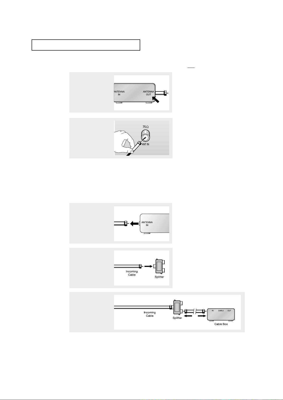
Connecting to a Cable Box that Descrambles All Channels
1
Find the cable that is connected to the ANTENNA
OUT terminal on your
cable box.
2
Connect the other end of
this cable to the VHF/UHF
antenna
terminal on the back of
the TV.
Connecting to a Cable Box that Descrambles Some Channels
If your cable box descrambles only some channels (such as premium channels), follow the
instructions below. You will need a two-way splitter, an RF (A/B) switch, and four lengths of
coaxial cable. (These items are available at most electronics stores.)
1
Find and disconnect the
cable that is connected to
the ANTENNA IN
terminal on your
cable box.
2
Connect this cable to a
two-way splitter.
3
Connect a coaxial cable
between an OUTPUT terminal on the splitter and
the IN terminal on the
cable box.
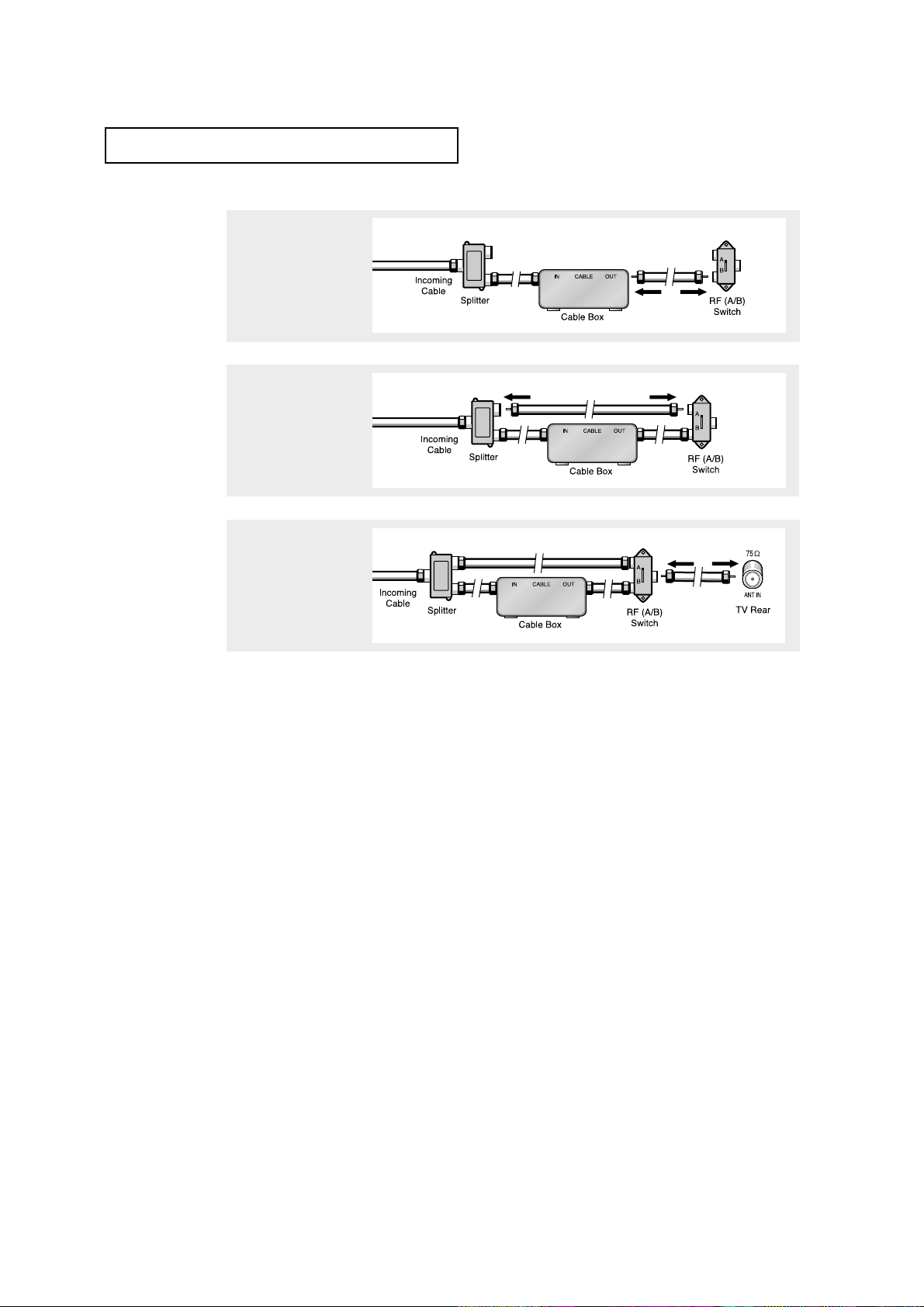
CHAPTER TWO: INSTALLATION 2.4
4
Connect a coaxial cable
between the ANTENNA
OUT terminal on the cable
box and the B–IN terminal
on the A/B switch.
5
Connect another cable
between the other OUT
terminal on the splitter
and the A–IN terminal on
the RF (A/B) switch.
6
Connect the last coaxial
cable between the OUT
terminal on the RF (A/B)
switch and the VHF/UHF
terminal on the rear of the
TV.
INSTALLATION
After you’ve made this connection, set the A/B switch to the “A” position for normal viewing.
Set the A/B switch to the “B” position to view scrambled channels. (When you set the A/B
switch to “B,” you will need to tune your TV to the cable box’s output channel, which is usually channel 3 or 4.)
2.5 CHAPTER TWO: INSTALLATION
INSTALLATION
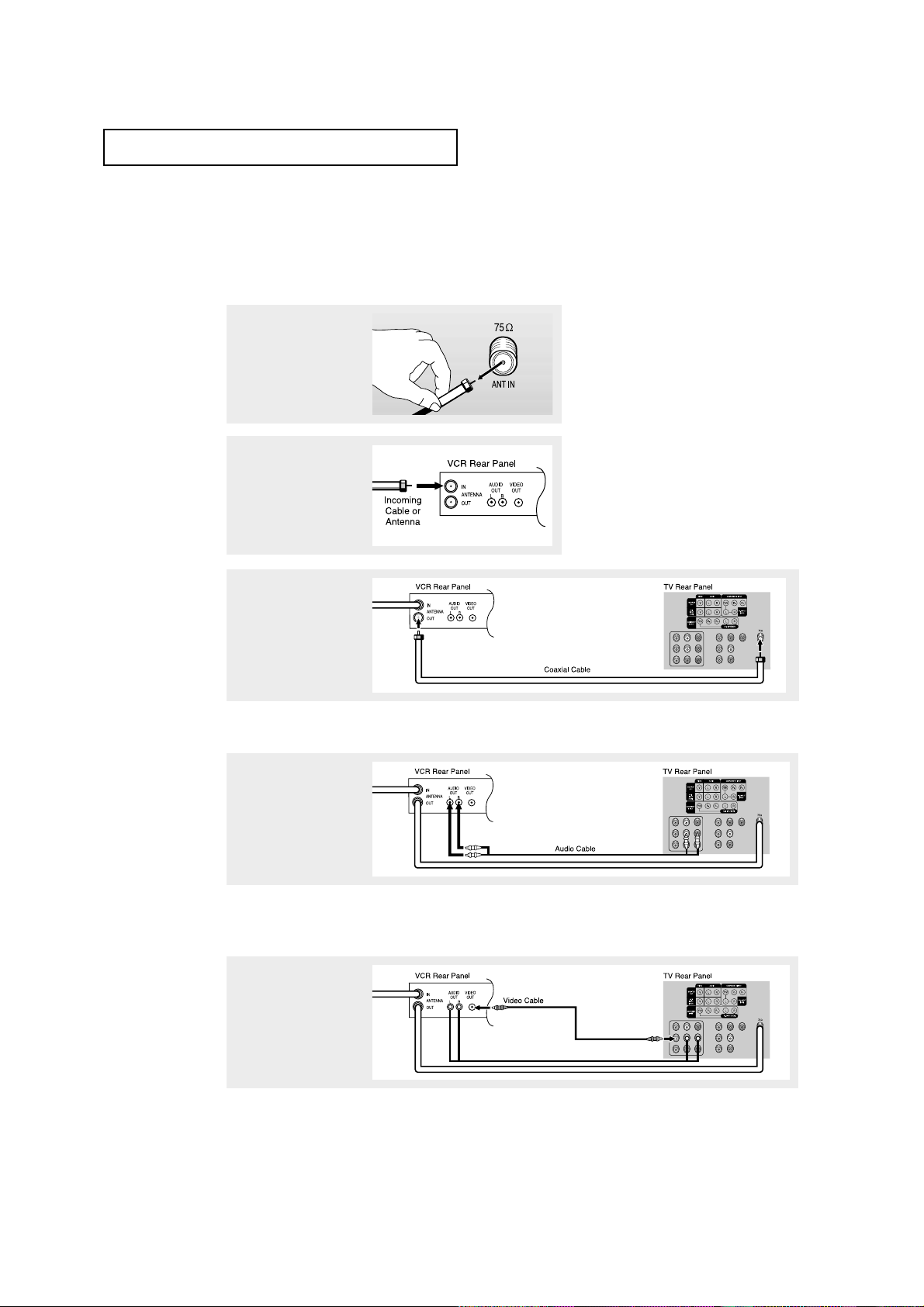
3
Connect a coaxial cable
between the ANTENNA
OUT terminal on the VCR
and the antenna
terminal on the TV.
4
Connect a set of audio
cables between the
AUDIO OUTjacks on the
VCR and the AUDIO
jacks(AV1~AV3) on the TV.
5
Connect a video cable
between the VIDEO OUT
jack on the VCR and the
VIDEO jack(AV1~AV3) on
the TV.
Follow the instructions in “Viewing a VCR or Camcorder Tape” to view your VCR tape.
A coaxial cable is usually included with a VCR. (If not, check your local electronics
store).
If you have a “mono” (non-stereo) VCR, use the Y-connector (not supplied) to hook up
to the left and right audio input jacks of the TV. If your VCR is stereo, you must connect two cables.
Connecting a VCR
These instructions assume that you have already connected your TV to an antenna or a
cable TV system (according to the instructions on pages 2.1-2.3). Skip step 1 if you have
not yet connected to an antenna or a cable system.
1
Unplug the cable or
antenna from the back of
the TV.
2
Connect the cable or
antenna to the
ANTENNA INterminal on
the back of the VCR.
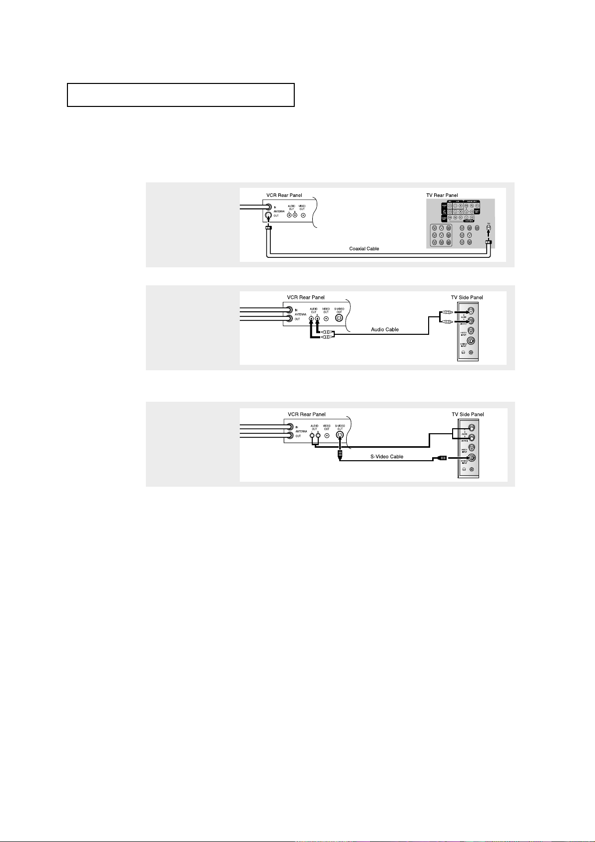
CHAPTER TWO: INSTALLATION 2.6
INSTALLATION
3
Connect an S-video cable
between the S-VIDEO OUT
jack on the VCR and the
S-VIDEO INPUT jack on
the TV.
An S-video cable is usually included with an S-VHS VCR. (If not, check your local
electronics store.)
Make sure the jacks you are using are underneath the number “1.”
2
Connect a set of audio
cables between the
AUDIO OUT jacks on the
VCR and the AUDIO
INPUT 1 jacks on the TV.
1
To begin, follow steps
1–3 in the previous
section to connect the
antenna or cable to your
VCR and your TV.
Connecting an S-VHS VCR
Your TV can be connected to an S-Video signal from an S-VHS VCR.
(This connection delivers a better picture as compared to a standard VHS VCR.)
2.7 CHAPTER TWO: INSTALLATION
Note: For an explanation of Component video, see your DVD player's owner's manual.
INSTALLATION
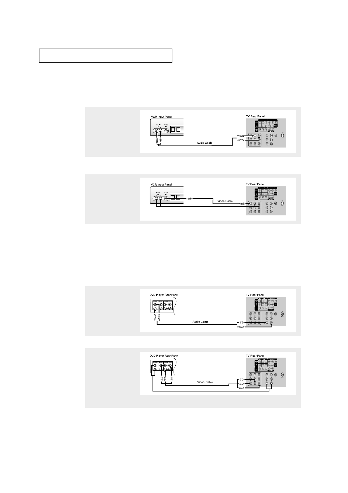
Connecting a DVD Player
(480i/480p)
The rear panel jacks on your TV make it easy to connect a DVD player to your TV.
1
Connect a set of audio
cables between the AV-2
INPUT(VCR) or AV-3
INPUT(VCR) jacks on the
TV and the AUDIO OUT
jacks on the DVD player.
2
Connect a video cable
between the COMPONENT 1 INPUT (Y/V, PB,
PR) or COMPONENT 2
INPUT (Y/V, PB, PR)jacks
on the TV and the DVDOUT (Y, PB, PR) jacks on
the DVD player.
Connecting a Second VCR to Record from the TV
Your TV can send out signals of its picture and sound to be recorded by a second VCR.
To do this, connect your second VCR as follows:
1
Connect a set of audio
cables between the
AUDIO OUTjacks on the
TV and the AUDIO IN
jacks on the VCR.
2
Connect a video cable
between the VIDEO OUT
jack on the TV and the
VIDEO IN jack on the VCR.
Refer to your VCR’s instructions for more information about how to record using this kind
of connection.
(The VCR input jacks might be either on the front or on back of the VCR.)
CHAPTER TWO: INSTALLATION 2.8
INSTALLATION
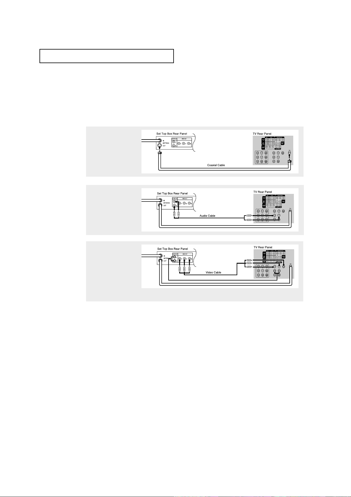
Connecting a Digital TV Set-Top Box
(480p/1080i)
Connect the Y, PB, and PRvideo outputs of the set-top box to their corresponding inputs
on the TV. Next, connect the Left and Right audio from the set-top box to the corresponding L and R terminals on the TV. (The connections for a typical set-top box are
shown below.)
2
Connect a set of audio
cables between the AV-3
INPUT(VCR) or AV-2
INPUT(VCR) jacks on the
TV and the AUDIO OUT
jacks on the Set Top Box.
3
Connect a video cable
between the COMPONENT 2 INPUT (Y/V, PB,
PR) or COMPONENT 1
INPUT (Y/V, PB, PR)jacks
on the TV and the VIDEO
OUT (Y, PB, PR) jacks on
the Set Top Box.
1
Connect a coaxial cable
between the ANTENNA
OUT terminal on the Set
Top Box and the antenna
terminal on the TV.
Note: For an explanation of Set top box, see your Set top box owner's manual.
 Loading...