

Samsung TW14N63/BWT, TX14N3F3X/NSI, TX14N53X/SEC, TX14N53X/XEE, TX14N5F3X/SEC Service Manual
...
Television Video Cassette Recorder
Chassis : C15C(REV.2)
Model : TW14N63/BWT TX14N3DF3X/XEG
TX14N3F3X/NSI TX14N53X/SEC
TX14N53X/XEE TX14N5F3X/SEC
TX14N73X/XEN TX14N7F3X/SEC
Television Video Cassette Recorder CONTENTS
Precautions
Specifications
Disassembly and Reassembly
Alignment and Adjustment (Mechanical)
Alignment and Adjustment (Electrical)
Troubleshooting
Exploded View and Parts List
Electrical Parts List
Block Diagram
Wiring Diagram
Schematic Diagrams
1.
2.
3.
4.
5.
6.
7.
8.
9.
10.
11.
1. Precautions
1-1 Safety Precautions
1. Be sure that all of the built-in protective
devices are replaced. Restore any missing
protective shields.
2. When reinstalling the chassis and its
assemblies, be sure to restore all protective
devices, including: nonmetallic control knobs
and compartment covers.
3. Make sure that there are no cabinet openings
through which people—particularly
children—might insert fingers and contact
dangerous voltages. Such openings include
the spacing between the picture tube and the
cabinet mask, excessively wide cabinet
ventilation slots, and improperly fitted back
covers.
If the measured resistance is less than 1.0
megohm or greater than 5.2 megohms, an
abnormality exists that must be corrected
before the unit is returned to the customer.
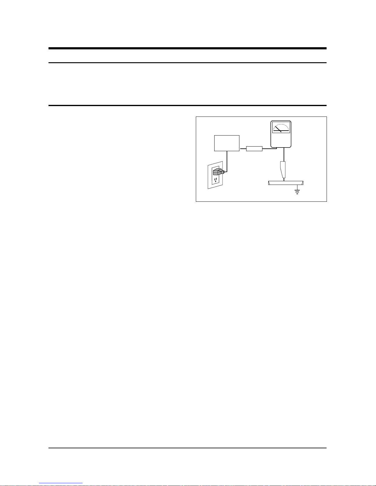
4. Leakage Current Hot Check (Figure 1-1):
Warning: Do not use an isolation
transformer during this test. Use a leakagecurrent tester or a metering system that
complies with American National Standards
Institute (ANIS C101.1, Leakage Current for
Appliances), and Underwriters Laboratories
(UL Publication UL1410, 59.7).
5. With the unit completely reassembled, plug
the AC line cord directly into the power
outlet. With the unit’s AC switch first in the
ON position and then OFF, measure the
current between a known earth ground (metal
water pipe, conduit, etc.) and all exposed
metal parts, including: antennas, handle
brackets, metal cabinets, screwheads and
control shafts. The current measured should
not exceed 0.5 milliamp. Reverse the powerplug prongs in the AC outlet and repeat the
test.
Fig. 1-1 AC Leakage Test
6. Antenna Cold Check:
With the unit’s AC plug disconnected from the
AC source, connect an electrical jumper across
the two AC prongs. Connect one lead of the
ohmmeter to an AC prong. Connect the other
lead to the coaxial connector.
7. X-ray Limits:
The picture tube is especially designed to prohibit X-ray emissions. To ensure continued
X-ray protection, replace the picture tube only
with one that is the same type as the original.
Carefully reinstall the picture tube shields and
mounting hardware; these also provide X-ray
protection.
8. High Voltage Limits:
High voltage must be measured each time servicing is done on the B+, horizontal deflection
or high voltage circuits. Correct operation of
the X-ray protection circuits must be
reconfirmed whenever they are serviced.
(X-ray protection circuits also may be called
“horizontal disable” or “hold-down”.)
Heed the high voltage limits. These include
the X–ray Protection Specifications Label, and
the Product Safety and X-ray Warning Note on
the service data schematic.
Precautions
Samsung Electronics 1-1
LEAKAGE
CURRENT
TESTER
DEVICE
UNDER
TEST
TEST ALL
EXPOSED METAL
SURFACES
3-WIRE CORD
ALSO TEST WITH
PLUG REVERSED
(USING AC ADAPTER
PLUG AS REQUIRED)
EARTH
GROUND
(READING SHOULD
NOT BE ABOVE
0.5mA)
Follow these safety, servicing and ESD precautions to prevent damage and protect against potential
hazards such as electrical shock and X-rays.

1-1 Safety Precautions (Continued)
9. High voltage is maintained within specified
limits by close-tolerance, safety-related
components and adjustments. If the high
voltage exceeds the specified limits, check
each of the special components.
10. Design Alteration Warning:
Never alter or add to the mechanical or
electrical design of this unit. Example: Do not
add auxiliary audio or video connectors. Such
alterations might create a safety hazard. Also,
any design changes or additions will void the
manufacturer’s warranty.
11. Hot Chassis Warning:
Some TV receiver chassis are electrically
connected directly to one conductor of the AC
power cord. If an isolation transformer is not
used, these units may be safely serviced only
if the AC power plug is inserted so that the
chassis is connected to the ground side of the
AC source.
To confirm that the AC power plug is inserted
correctly, do the following: Using an AC
voltmeter, measure the voltage between the
chassis and a known earth ground. If the
reading is greater than 1.0V, remove the AC
power plug, reverse its polarity and reinsert.
Re-measure the voltage between the chassis
and ground.
12. Some TV chassis are designed to operate with
85 volts AC between chassis and ground,
regardless of the AC plug polarity. These units
can be safely serviced only if an isolation
transformer inserted between the receiver and
the power source.
13. Some TV chassis have a secondary ground
system in addition to the main chassis ground.
This secondary ground system is not
isolated from the AC power line. The two
ground systems are electrically separated by
insulating material that must not be defeated
or altered.
14. Components, parts and wiring that appear to
have overheated or that are otherwise
damaged should be replaced with parts that
meet the original specifications. Always
determine the cause of damage or overheating, and correct any potential hazards.
15. Observe the original lead dress, especially
near the following areas: Antenna wiring,
sharp edges, and especially the AC and high
voltage power supplies. Always inspect for
pinched, out-of-place, or frayed wiring. Do
not change the spacing between components
and the printed circuit board. Check the AC
power cord for damage. Make sure that leads
and components do not touch thermally hot
parts.
16. Picture Tube Implosion Warning:
The picture tube in this receiver employs
“integral implosion” protection. To ensure
continued implosion protection, make sure
that the replacement picture tube is the same
as the original.
17. Do not remove, install or handle the picture
tube without first putting on shatterproof
goggles equipped with side shields. Never
handle the picture tube by its neck. Some
“in-line” picture tubes are equipped with a
permanently attached deflection yoke; do not
try to remove such “permanently attached”
yokes from the picture tube.
18. Product Safety Notice:
Some electrical and mechanical parts have
special safety-related characteristics which
might not be obvious from visual inspection.
These safety features and the protection they
give might be lost if the replacement component differs from the original—even if the
replacement is rated for higher voltage,
wattage, etc.
Components that are critical for safety are
indicated in the circuit diagram by shading,
( ) or ( ).
Use replacement components that have the
same ratings, especially for flame resistance
and dielectric strength specifications.
A replacement part that does not have the
same safety characteristics as the original
might create shock, fire or other hazards.
Precautions
1-2 Samsung Electronics
!

1-2 Servicing Precautions
1. Servicing precautions are printed on the
cabinet. Follow them.
2. Always unplug the unit’s AC power cord from
the AC power source before attempting to: (a)
Remove or reinstall any component or
assembly, (b) Disconnect an electrical plug or
connector, (c) Connect a test component in
parallel with an electrolytic capacitor.
3. Some components are raised above the printed
circuit board for safety. An insulation tube or
tape is sometimes used. The internal wiring is
sometimes clamped to prevent contact with
thermally hot components. Reinstall all such
elements to their original position.
4. After servicing, always check that the screws,
components and wiring have been correctly
reinstalled. Make sure that the portion around
the serviced part has not been damaged.
5. Check the insulation between the blades of the
AC plug and accessible conductive parts
(examples: metal panels, input terminals and
earphone jacks).
6. Insulation Checking Procedure: Disconnect the
power cord from the AC source and turn the
power switch ON. Connect an insulation
resistance meter (430V) to the blades of the AC
plug.
The insulation resistance between each blade
of the AC plug and accessible conductive parts
(see above) should be greater than 1 megohm.
7. Never defeat any of the B+ voltage interlocks.
Do not apply AC power to the unit (or any of
its assemblies) unless all solid-state heat sinks
are correctly installed.
8. Always connect a test instrument’s ground
lead to the instrument chassis ground before
connecting the positive lead; always remove
the instrument’s ground lead last.
Precautions
Samsung Electronics 1-3
Warning1: First read the “Safety Precautions” section of this manual. If some unforeseen circumstance creates a conflict between
the servicing and safety precautions, always follow the safety precautions.
Warning2: An electrolytic capacitor installed with the wrong polarity might explode.

1. Some semiconductor (“solid state”) devices
are easily damaged by static electricity. Such
components are called Electrostatically
Sensitive Devices (ESDs); examples include
integrated circuits and some field-effect
transistors. The following techniques will
reduce the occurrence of component damage
caused by static electricity.
2. Immediately before handling any semicon
ductor components or assemblies, drain the
electrostatic charge from your body by
touching a known earth ground. Alternatively,
wear a discharging wrist-strap device. (Be
sure to remove it prior to applying power—
this is an electric shock precaution.)
3. After removing an ESD-equipped assembly,
place it on a conductive surface such as
aluminum foil to prevent accumulation of
electrostatic charge.
4. Do not use freon-propelled chemicals. These
can generate electrical charges that damage
ESDs.
5. Use only a grounded-tip soldering iron when
soldering or unsoldering ESDs.
6. Use only an anti-static solder removal device.
Many solder removal devices are not rated as
“anti-static”; these can accumulate sufficient
electrical charge to damage ESDs.
7. Do not remove a replacement ESD from its
protective package until you are ready to
install it. Most replacement ESDs are
packaged with leads that are electrically
shorted together by conductive foam,
aluminum foil or other conductive materials.
8. Immediately before removing the protective
material from the leads of a replacement ESD,
touch the protective material to the chassis or
circuit assembly into which the device will be
installed.
9. Minimize body motions when handling
unpackaged replacement ESDs. Motions such
as brushing clothes together, or lifting a foot
from a carpeted floor can generate enough
static electricity to damage an ESD.
Precautions
1-4 Samsung Electronics
1-3 Precautions for Electrostatically Sensitive Devices (ESDs)

Samsung Electronics 2-1
2. Specifications
The descriptions and characteristics given in this booklet are given for information purposes only and
are subject to modification without notice.
TELEVISION PART
Colour systems PAL(option) / SECAM(option) (UK;PAL)
TV standards L/L’(option), B/G(option), D/K(option) (UK;I)
Number of channels 100 programmes
Reception range/cable TV Hyperband/interband tuner
Aerial input 75 Ohms, coaxial cable
VCR PART
Format VHS standard
(PAL / SECAM(option) / MESECAM(option) / NTSC in playback only)
Heads Video: 2 rotary heads, LP(option), 4 Heads(option)
Audio/Control: 1 stationary head (linear)
Erase: 1 full track erase head
System Video Normal CCIR
System Audio Mono / NICAM&A2-STEREO
Luminance FM azimuth recording
Colour Down converted subcarrier phase shifted direct recording
FF/REW time Less than 100 seconds in FF with E-120
Wow and flutter (WTD) 0.4% maximum (SP)
Frequency response 100 Hz - 8 KHz
GENERAL
Power supply 220-240V~, 50Hz (110-260V~, 50/60Hz; option),(160-300V~50/60Hz;Russia)
Consumption 14”15” (60W)
20”/21” (90W)
Audio output power 14”15” (1.5W)
20” (3W)
21” (1.5Watts x 2)
Number of loudspeakers 14”/15”/20” (1)
21” (2)
Tube size 14” (37cm/34cmV)
15” (39cm/36cmV)
20” (51cm/48cmV)
21” (55cm/51cmV)
Tube type BLACK MATRIX
Sockets 1 full RGB SCART on the rear
1 RCA input (audio and video) on the front
Earphones output (3.5 mm mini-jack)
1 aerial/cable TV coaxial input
Dimensions (W x D x H) 14” (368.5 x 388 x 381)
15” (411 x 401 x 417)
20” (488 x 477 x 488)
21” (520 x 495 x 508)
Weight 14” (11.7 kg)
15” (14.8 kg)
20” (20.4 kg)
21” (23.2 kg)
Operating temperature 5°C - 40°C (41°F - 104°F)
Relative humidity 10% - 75%

MEMO
2-2 Samsung Electronics
Disassembly and Reassembly
Samsung Electronics 3-1
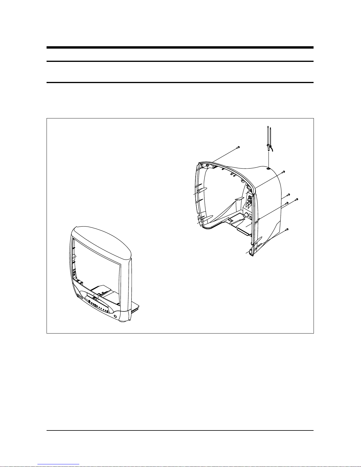
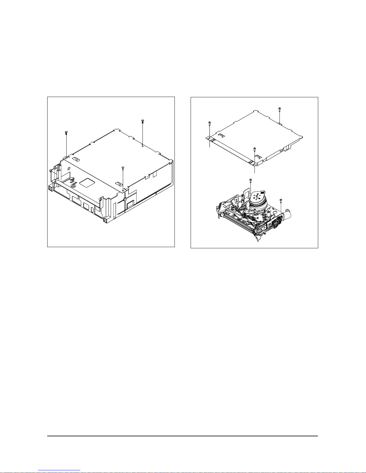
1. Remove the screws located on the side of the back cover.
3. Disassembly and Reassembly
3-1 Disassembly
3-1-1 Back Cover Removal
Disassembly and Reassembly
3-2 Samsung Electronics
Back Cover Removal
Disassembly and Reassembly
Samsung Electronics 3-3
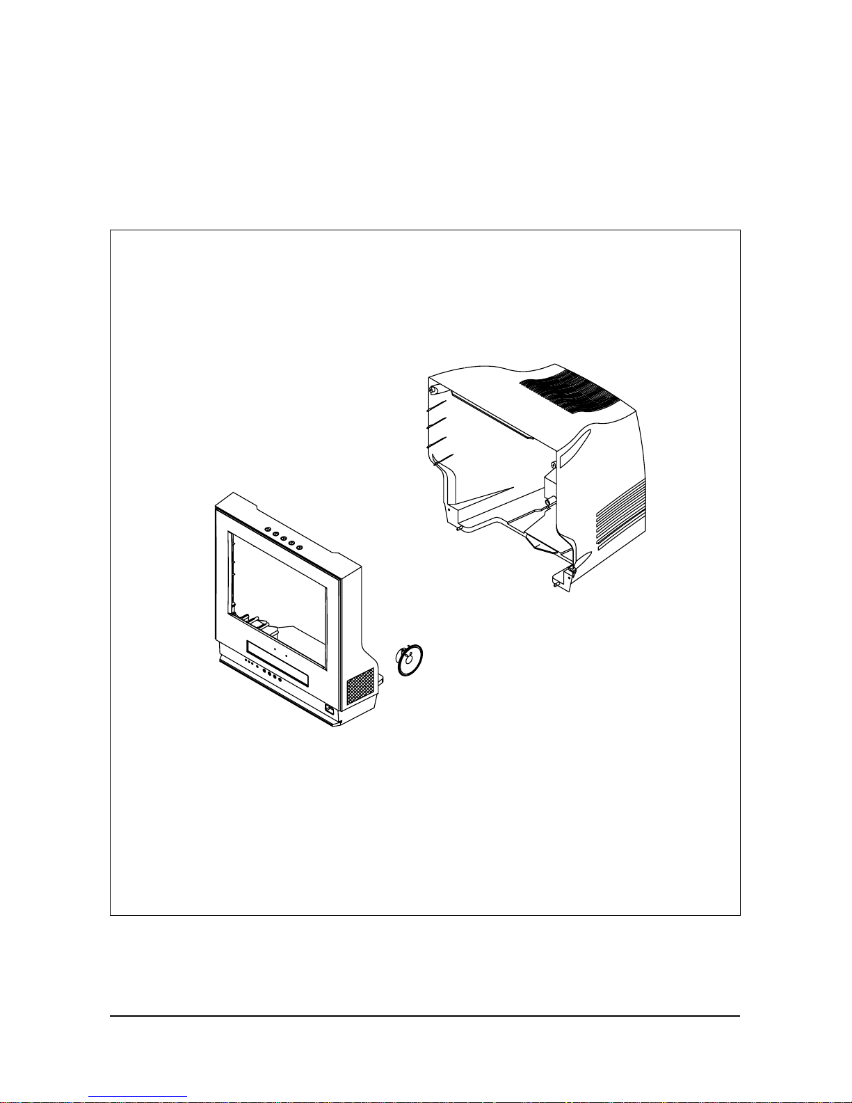
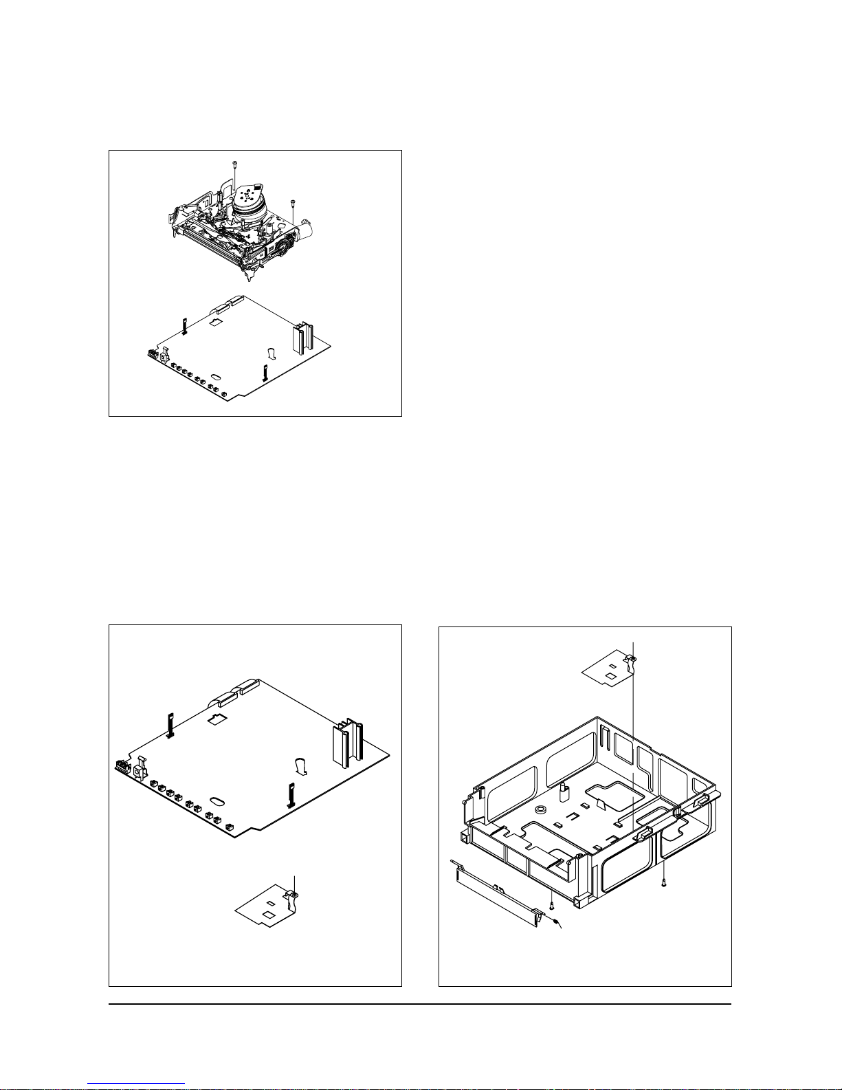
3-1-2 Main Assembly Removal
1. Release two connectors between sub PCB and Main Assembly.
2. Pull the Main Assembly backwards to remove.
Disassembly and Reassembly
3-4 Samsung Electronics
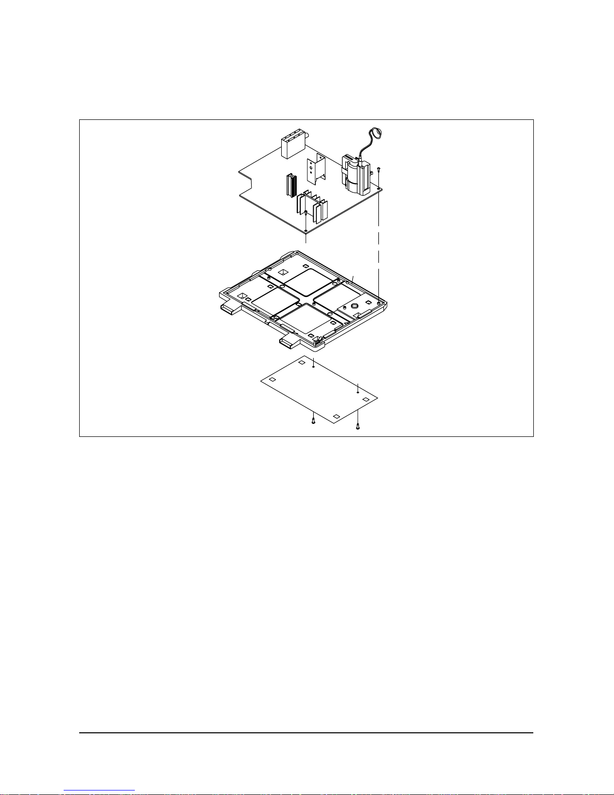
3-1-3 Monitor Frame Removal
1. Remove 3 screws from the Main Assembly. Remove the dust cover.
2. Remove 4 screws from the Deck Assembly.
Disassembly and Reassembly
Samsung Electronics 3-5
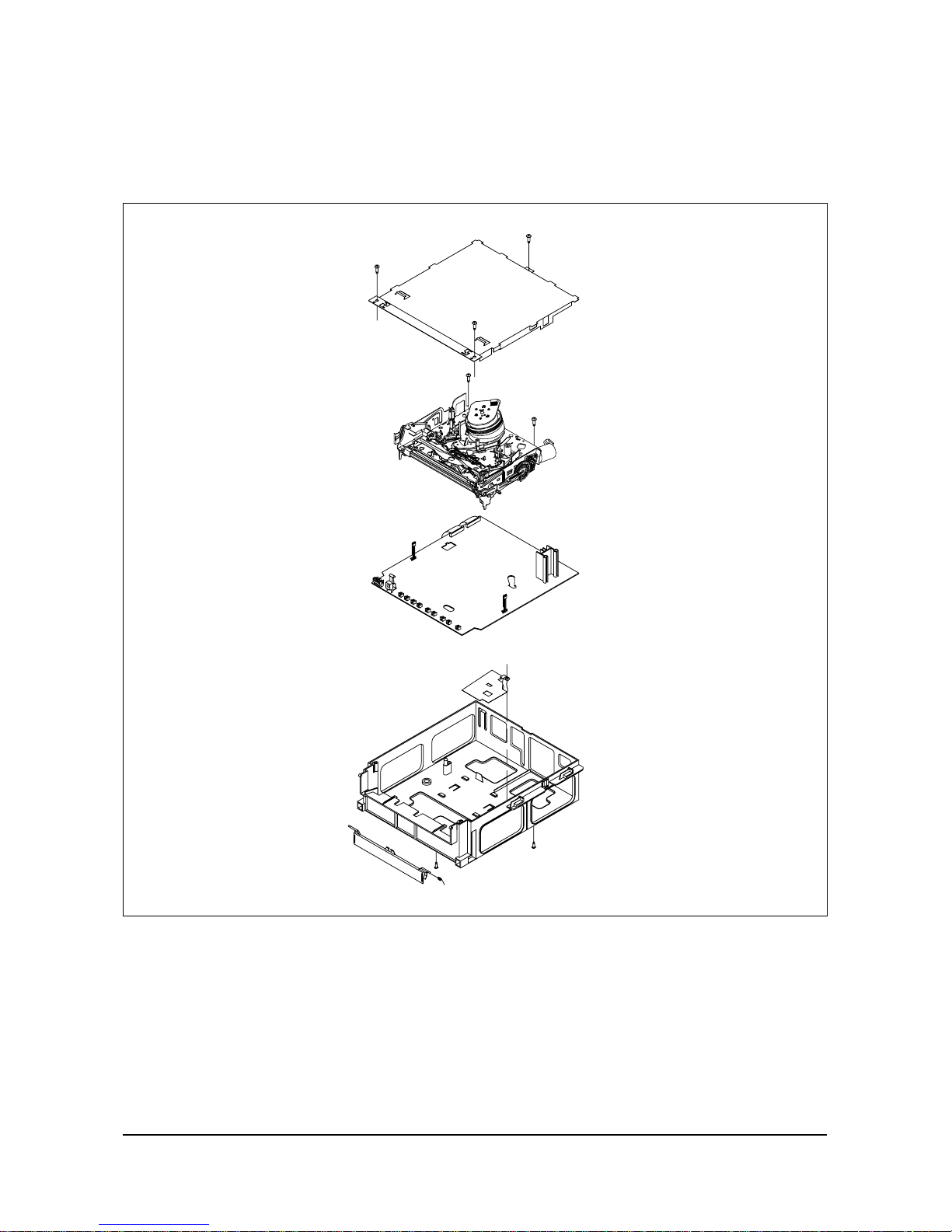
3-1-4 Deck Assembly Removal 3-1-5 Main Assembly Removal
1. Remove 2 screws holding the bottom cover.
2. Remove one screw from Main PCB
Assembly. Take off the deck Assembly.
1. Remove 2 screws holding the upper chassis
housing.
2. Remove 3 screws holding the deck assembly.
3. Lift the deck assembly upward to remove.
Disassembly and Reassembly
3-6 Samsung Electronics
3-1-6 Top Cabinet Removal
1. Remove two (2) screws located at the rear of
the top cabinet.
2. Carefully lift the back of the top cabinet and
shield it to the rear to remove.
3-1-7 Top Cabinet Removal
3-1-8 Top Cabinet Removal
Samsung Electronics
4-1
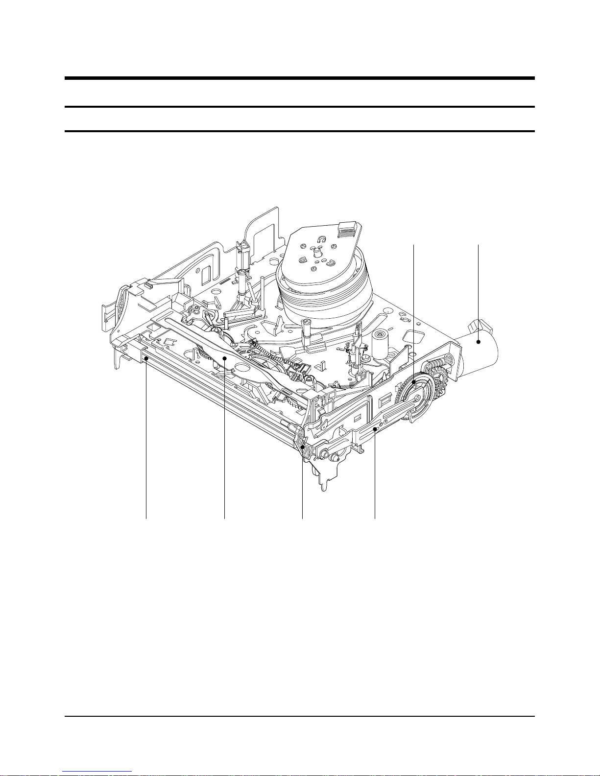
Œ
´
ˇ
¨
ˆ
Ø
Fig. 4-1 Top parts Location-1
ΠGEAR FL CAM
´ MOTOR LOADING ASS’Y
ˇ LEVER FL ARM ASS’Y
¨ HOLDER FL CASSETTE ASS’Y
ˆ LEVER FL DOOR
Ø SLIDER FL DRIVE
4. Disassembly and Reassembly
4-1 Deck Parts Locations
4-1-1 Top View
4-2
Samsung Electronics
Disassembly and Reassembly
Œ
´ ˇ ¨
ˆ
Ø
∏”’ Ô ˝
Ò
”
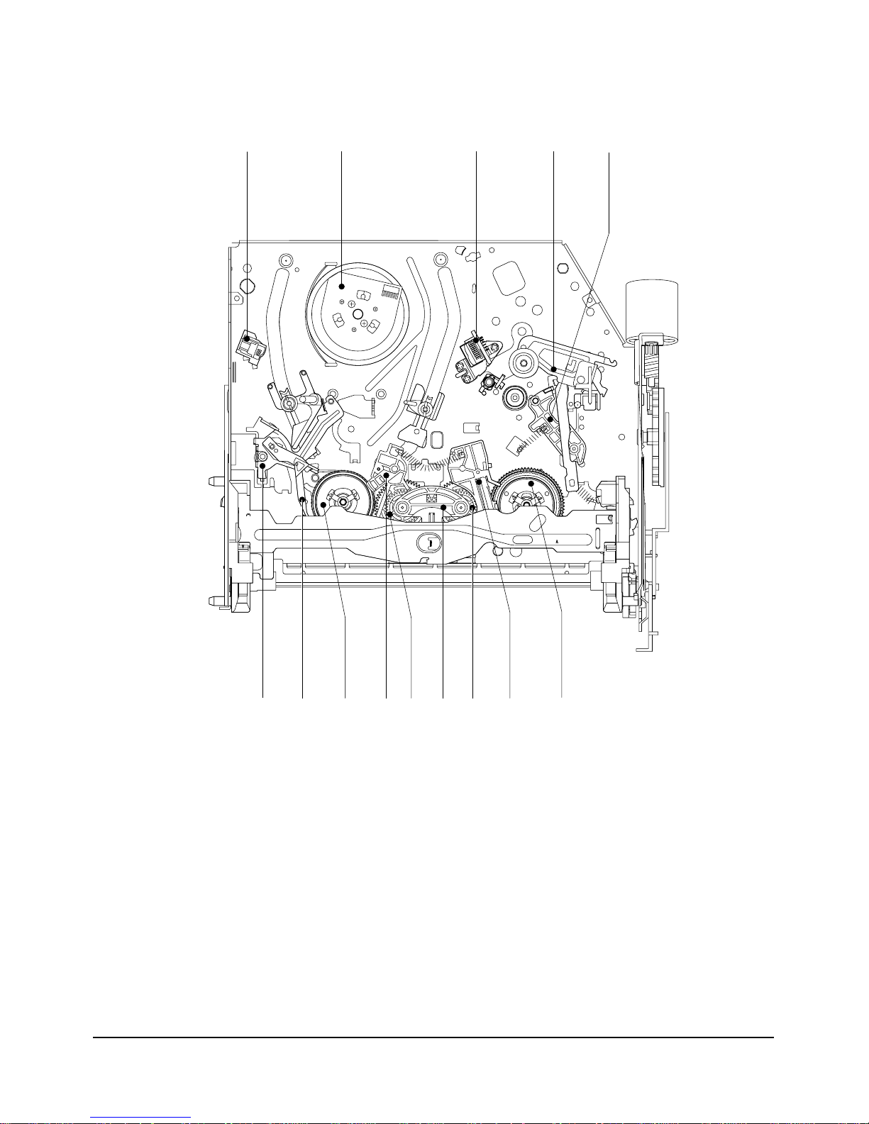
Fig. 4-2 Top Parts Location-2
ΠFE HEAD
´ CYLINDER ASS’Y
ˇ ACE HEAD ASS’Y
¨ LEVER UNIT PINCH ASS’Y
ˆ LEVER #9 GUIDE ASS’Y
Ø LEVER TENSION ASS’Y
∏ BAND BRAKE ASS’Y
” DISK S REEL
’ LEVER S BRAKE ASS’Y
˝ GEAR IDLE
Ô LEVER IDLE
LEVER T BRAKE ASS’Y
Ò DISK T REEL
Disassembly and Reassembly
Samsung Electronics
4-3
4-1-2 Bottom View
Œ
´ˇ
¨
ˆ
Ø
∏
”
’
˝
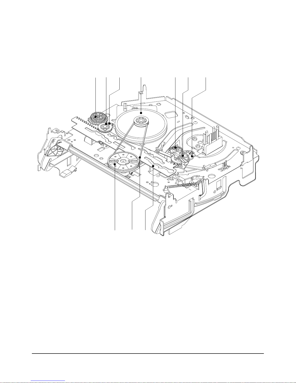
Fig. 4-3 Bottom Parts Location
ΠGEAR JOINT 1
´ GEAR JOINT 2
ˇ BRACKET GEAR
¨ MOTOR CAPSTAN ASS’Y
ˆ LEVER T LOAD ASS’Y
Ø GEAR LOADING DRIVE
∏ LEVER S LOAD ASS’Y
” HOLDER CLUTCH ASS’Y
’ BELT PULLEY
˝ SLIDER CAM
4-4
Samsung Electronics
Disassembly and Reassembly
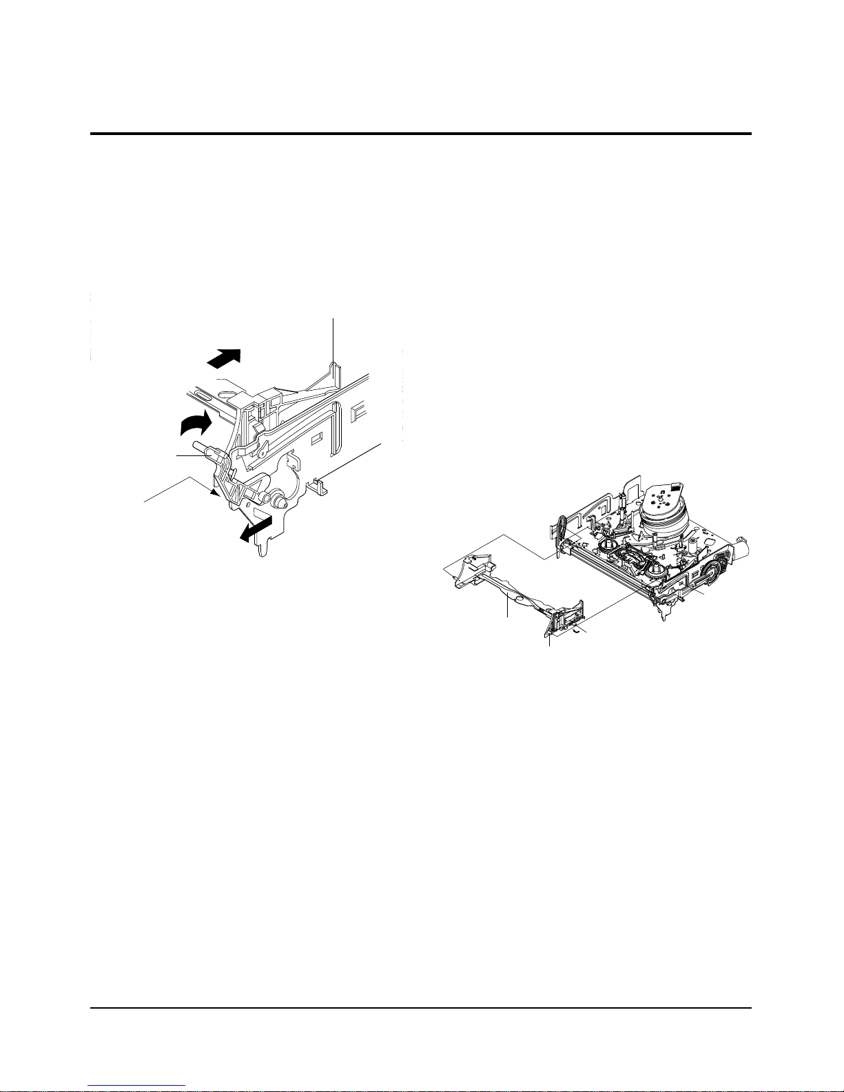
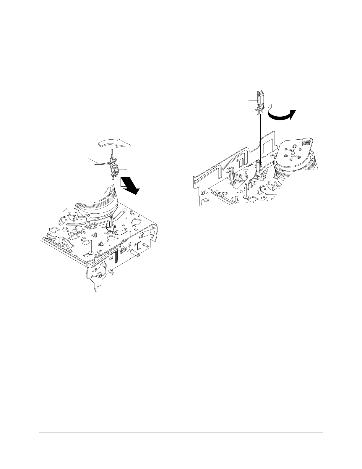
4-2-1 Lever FL Door Removal
1) Push the Holder FL Cassette Ass'y Πabout 20mm
in the direction of arrow “A”.
2) Rotate the Lever FL Door ´ in the direction of
arrow “B”.
3) Release the Hook ˇ and Remove the Lever FL
Door ´ in the direction of arrow “C”.
"B"
"C"
"A"
´ LEVER FL DOOR
ˇ HOOK
ΠHOLDER FL CASSETTE ASS'Y
4-2-2 Holder FL Cassette Ass’y Removal
1) Pull the Holder FL Cassette Ass'y Πto the eject
position.
2) Pull the Holder FL Cassette Ass'y Πas grasping
the Holder FL Cassette Ass'y Πand Lever FL
Cassette-R ´ in the same time to release hooking
from Main Base until the Boss [A] of Holder FL
Cassette Ass'y Πis taken out from the Rail [B].
3) Lift the Holder FL Cassette Ass'y Œ, in this time,
you have to grasp the Lever FL Cassette-R ´
Continuously until the Holder FL Cassette Ass'y
Πis taken out completely.
Note : Be sure to insert Lever FL Cassette-R ´ in the
direction of “A” to prevent separation and breakage
of the Lever FL Cassette-R ´ at disassembling and
reassembling.
ΠHOLDER FL
CASSETTEE ASS`Y
BOSS [A]
RAIL [B]
´ LEVER FL CASSETTEE -R
"A"
4-2 Main Deck
Fig. 4-4 Lever FL Door Removal
Fig. 4-5 Holder FL Cassette Ass’y Removal
Disassembly and Reassembly
Samsung Electronics
4-5
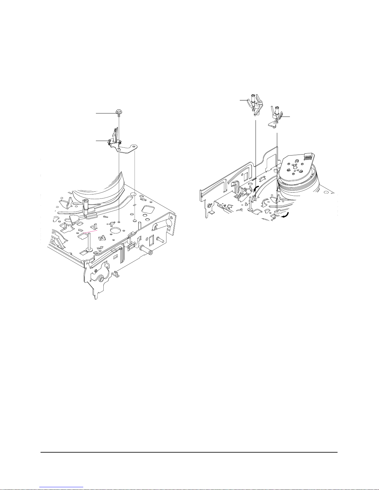
4-2-4 Lever FL Arm Ass’y Removal
1) Push the hole “A” in the direction of arrow “B”
use the pin.(about Dia. 2.5)
2) Pull out the Lever FL Arm Ass'y Πfrom the Boss
of Main Base.
3) Remove the Lever FL Arm Ass'y Πin the direction
of arrow “C”.
ΠGEAR FL CAM
GEAR WORM WHEEL
POST
TIMING POINT
Fig. 1-7 Gear FL Cam, Gear Worm
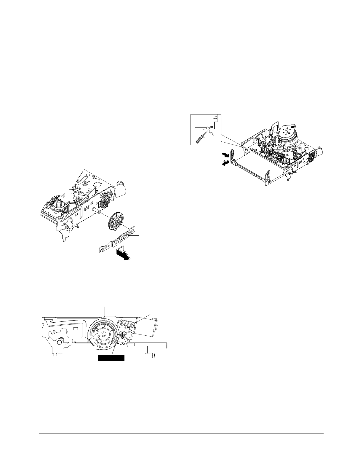
4-2-3 Slider FL Drive, Gear FL Cam Removal
1) Pull the Slider FL Drive Πto the front direction.
2) Remove the Slider FL Drive Πin the direction of
arrow. (Refer to Fig. 1-6)
3) Remove the Gear FL cam ´.
Note : When reinstalling be sure to reassemble Slider
FL drive Πafter you insert the Boss of Lever FL
ARM-R in Groove of Slider Fl drive Œ.
Assembly : Align the Gear FL Cam Πwith the Gear
worm wheel Post as shown drawing.
(Refer to Timing point)
ΠSLIDER FL DRIVE
´ GEAR FL CAM
Fig. 4-6 Slider FL Drive Removal
ΠLEVER FL ARM ASS`Y
"C"
"B"
PIN
HOLE "A"
Fig. 4-8 Lever FL Arm Ass’y Removal
4-6
Samsung Electronics
Disassembly and Reassembly
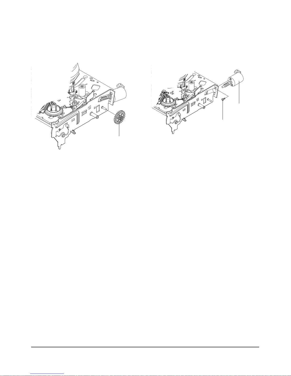
4-2-5 Gear Worm Wheel Removal
1) Remove the Gear Worm wheel Œ.
ΠGEAR WORM WHEEL
Fig. 4-9 Gear Worm Wheel Removal
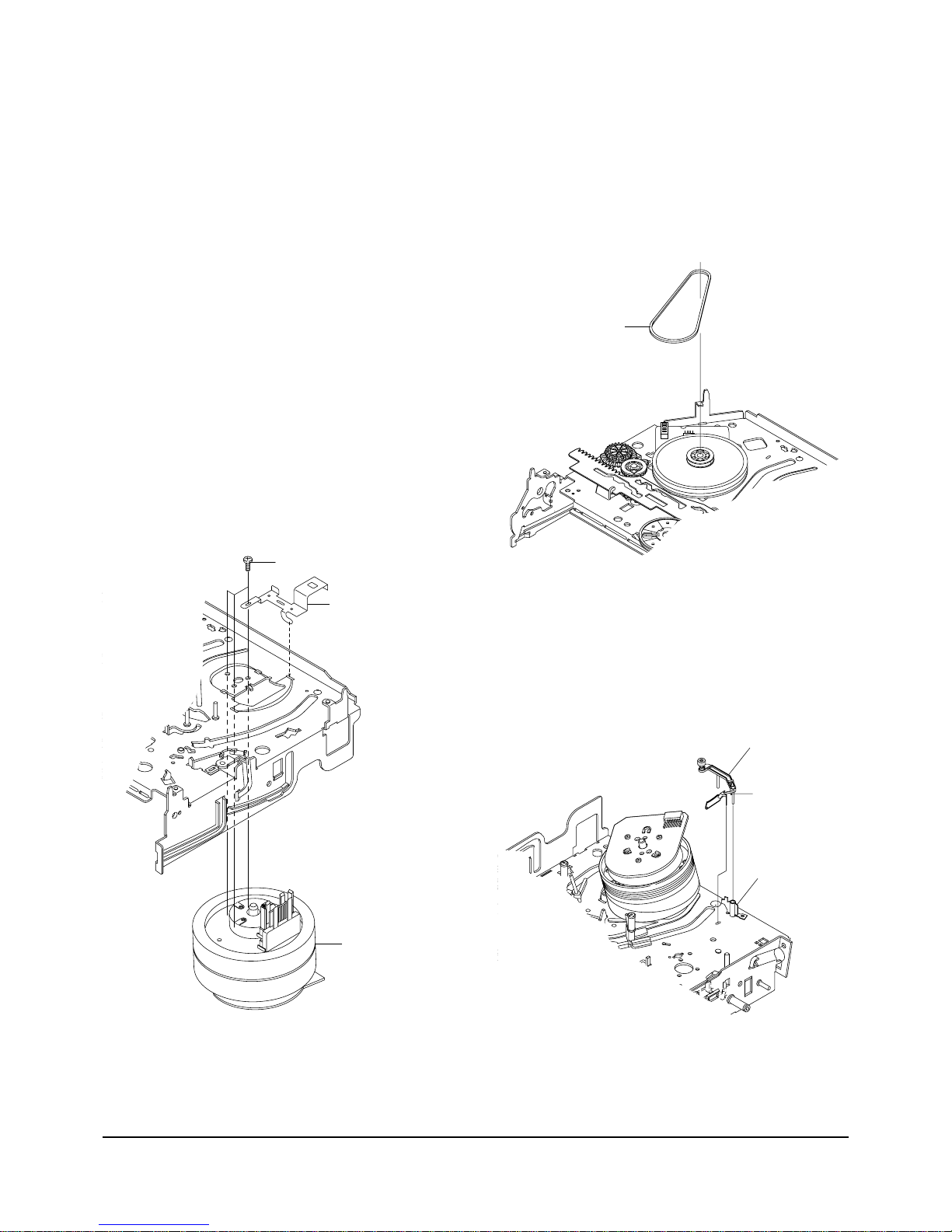
4-2-6 Motor Loading Ass’y Removal
1) Remove the screw Œ.
2) Remove the Motor Loading Ass’y ´.
´ MOTOR LOADING ASS`
Y
ΠSCREW
Fig. 4-10 Motor Loading Ass’y Removal
Disassembly and Reassembly
Samsung Electronics
4-7
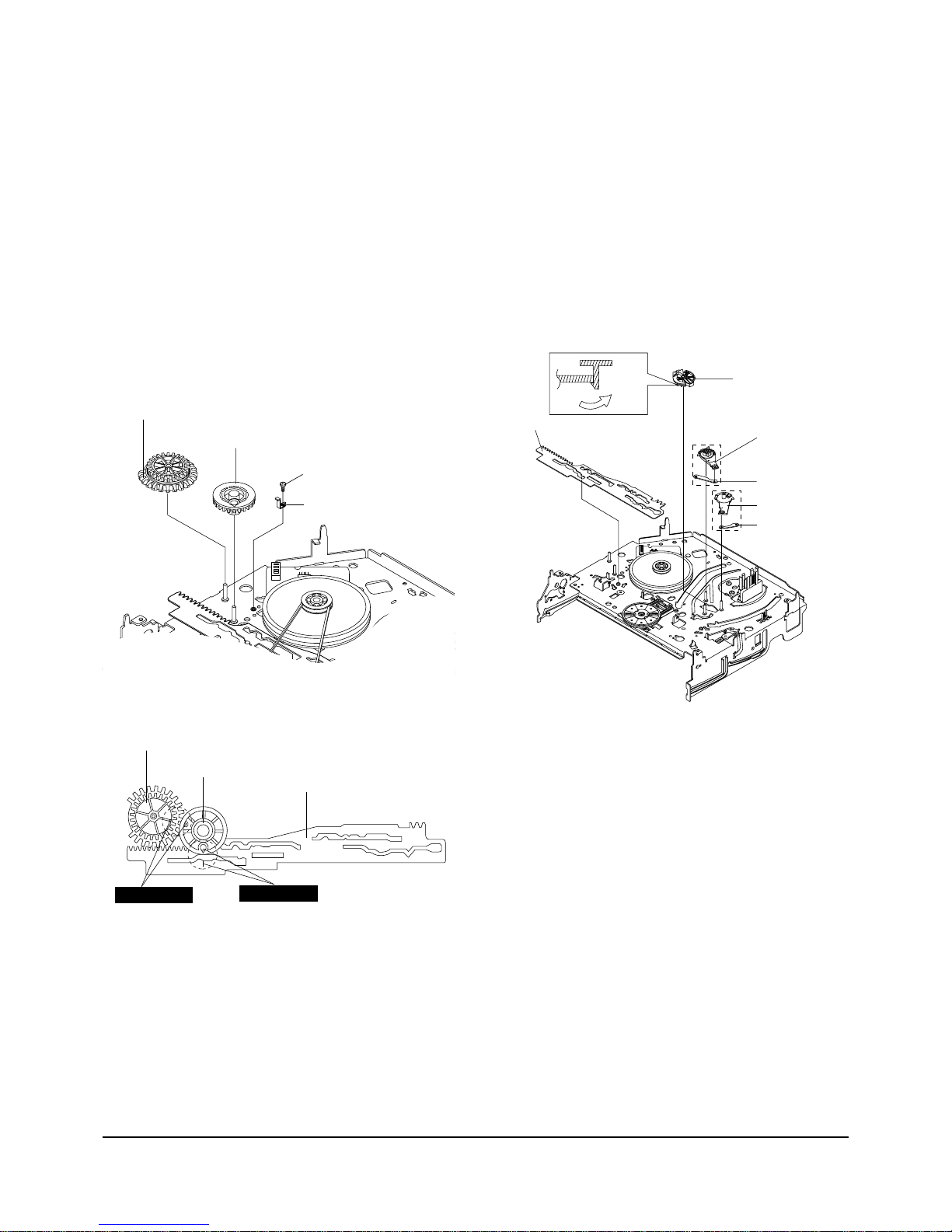
4-2-7 Bracket Gear, Gear Joint 2, 1 Removal
1) Remove the SCREW Œ.
2) Remove the Bracket Gear ´.
3) Remove the Gear Joint 2 ˇ.
4) Remove the Gear Joint 1 ¨.
Assembly :
1) Be sure to align dot mark of Gear Joint 1
Œ
with
dot mark of Gear Joint 2 ´ as shown Fig 4-12.
(Refer to Timing point1)
2) Confirm the Timing Point 2 of the Gear Joint 2 ´
and Slider Cam ˇ.
ΠSCREW
´ BRAKET GEAR
¨ GEAR JOINT 1
ˇ GEAR JOINT 2
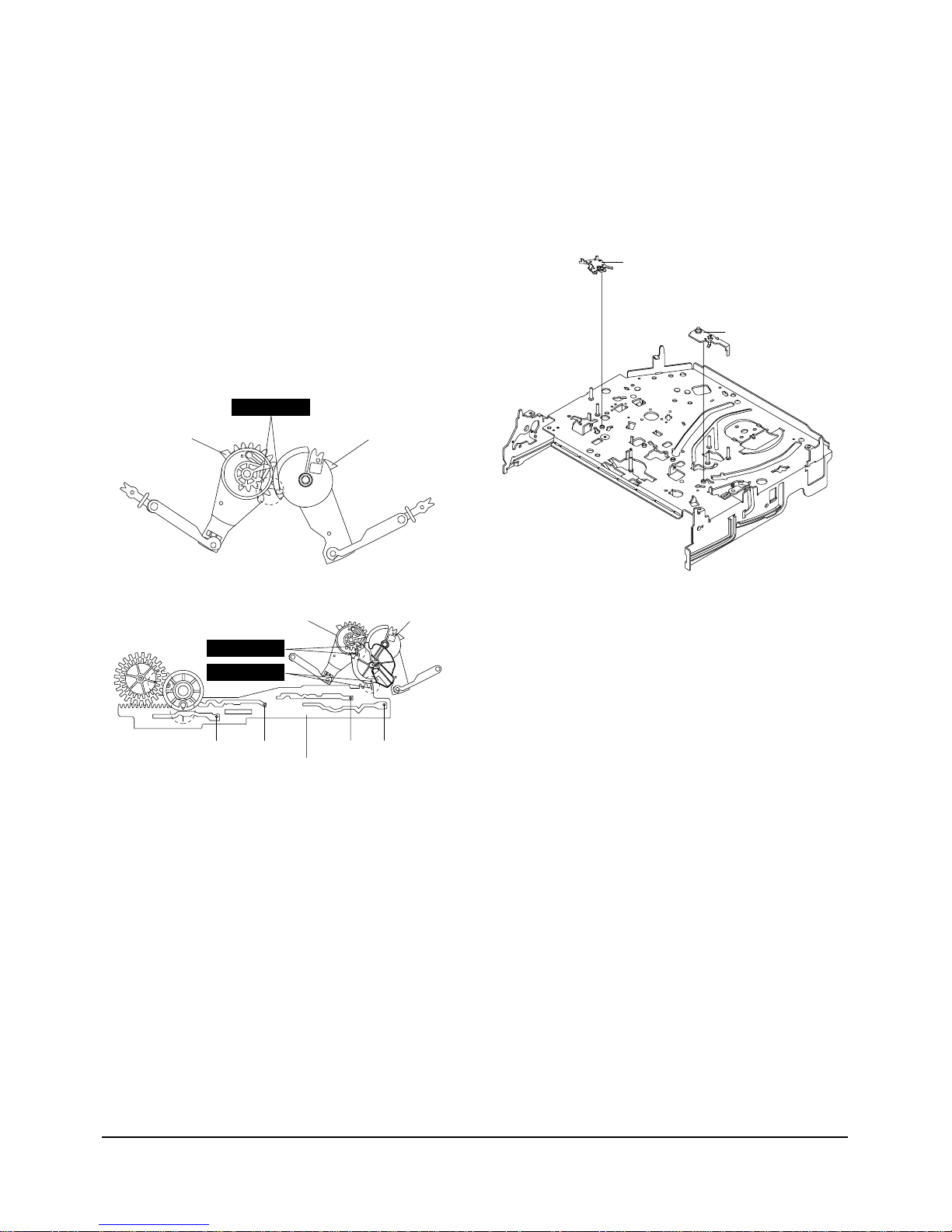
4-2-8 Gear Loading Drive, Slider Cam,
Lever Load S, T Ass’y Removal
1) Remove the Belt Pulley. (Refer to Fig. 4-30)
2) Remove the Gear Loading Drive Πafter releasing
Hook [A] in the direction arrow as shown in detail
drawing.
3) Remove the Slider Cam ´.
4) Remove the Lever Load ˇ, Link Load ˆ & Lever
Load ¨, Link Load Ø.
ΠGEAR LOADING DRIVE
ˆ LINK LOAD S
ˇ LEVER LOAD S
¨ LEVER LOAD T
Ø LINK LOAD T
´ SLIDE CAM
HOOK(A)
Fig. 4-11 Bracket Gear, Gear Joint 1,2 Removal
ΠGEAR JOINT1
´ GEAR JOINT2
ˇ SLIDER CAM
TIMING POINT 1
TIMING POINT 2
Fig. 4-12 Gear Joint 1,2 Assembly
Fig. 4-13 Gear Loading Drive, Slider Cam,
Lever T, S Load Ass’y Removal
4-8
Samsung Electronics
Disassembly and Reassembly
4-2-9 Gear Loading Drive, Slider Cam,
Lever Load S, T Ass’y Assembly
1) When reinstalling, be sure to align dot of Lever
Load T Ass'y
Œ
with dot of Lever Load S Ass'y ´
as shown in drawing, (Refer to Timing Point 1).
2) Insert the Pin A,B,C,D into the Slider Cam ˇhole,
3) Be sure to align dot of Lever Load T Πand dot of
Gear Loading Drive ¨, (Refer to Timing Point 2).
4) Aline dot of Gear Loading drive ¨ with mark of
Slider Cam ˇ as shown in drawing(Refer to
Timing Point 3).
´ LEVER LOAD S
Œ
LEVER LOAD T
LEVER LOAD S
LEVER LOAD T
PIN A
PIN C
PIN B
PIN D
ˇ SLIDER CAM
TIMING POINT 2
TIMING POINT 1
TIMING POINT 3
4-2-10 Lever Pinch Drive,
Lever Tension Drive Removal
1) Remove the Lever Pinch Drive Œ, Lever Tension
Drive ´.
ΠLEVER PINCH DRIVE
´ LEVER TENSION DRIVE
Fig. 4-14 Gear Loading Drive, Slider Cam,
Lever Load S, T Ass’y Assembly
Fig. 4-15 Lever Pinch Drive,
Lever Tension Drive Removal
Disassembly and Reassembly
Samsung Electronics
4-9
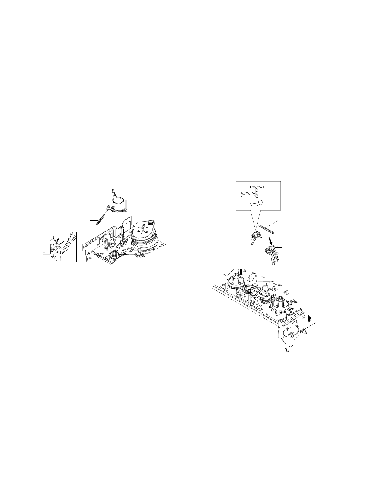
4-2-11 Lever Tension Ass’y,
Band Brake Ass’y Removal
1) Remove the Lever Brake S Ass'y (Refer to Fig 4-17).
2) Remove the Spring Tension Lever Œ.
3) Rotate stopper of Main Base in the direction of
arrow “A”.
4) Lift the Lever Tension Ass'y ´ & Band brake
Ass'y ˇ.
Note :
1) When replacing the Lever Tension Ass'y ´, be sure
to apply Grease on the post,
2) Take care not to touch stain on the felt side, and not
to be folder and broken Band brake Ass'y
3) After Lever Tension Ass'y seated, Rotate stopper of
Main Base to the Mark[B].
ΠSPRING TENTION LEVER
STOPPER
MARK[B]
"A"
´ LEVER TENTION ASS`Y
ˇ BAND BRAKE ASS`Y
4-2
-12 Lever Brake S, T Ass’y
Removal
1) Release the Hook [A] and the Hook [B], [C] in the
direction of arrow as shown in Fig 4-17.
2) Lift the Lever S, T Brake Ass'y Œ, ´ with spring
brake ˇ.
Assembly :
1)Assembly the Lever S Brake Ass'y Πon the Main
Base.
2)Assembly the Lever T Brake Ass'y ´ with spring
brake ˇ.
Note : Take extreme care not to be folded and
transformed Spring Brake at removing or reinstalling.
ΠLEVER S BRAKE ASS`Y
´ LEVER T BRAKE ASS`Y
ˇ SPRING BRAKE
HOOK(B)
HOOK(C)
HOOK(A)
Fig. 4-16 Lever Tension Ass’y,
Band Brake Ass’y Removal
Fig. 4-17 Lever Brake S, T Ass’y Removal
4-10
Samsung Electronics
Disassembly and Reassembly
ΠDISK S REEL
´ DISK T REEL
Fig. 4-19 Disk S, T Reel Removal
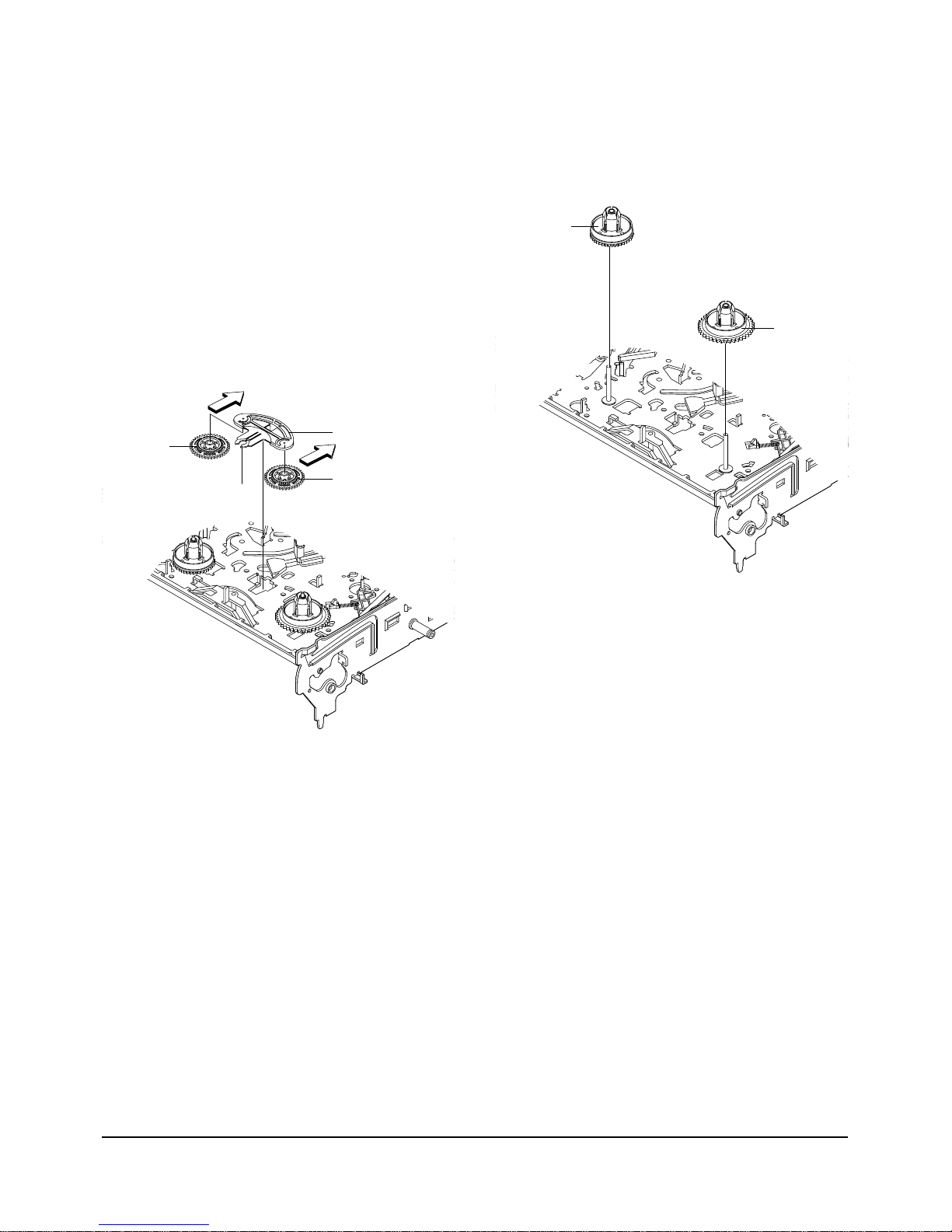
4-2-13 Gear Idle Ass’y Removal
1) Push the Lever Idle Πin the direction of arrow
“A”, “B”.
2) Lift the Lever Idle Œ.
Assembly :
1) Apply oil in two Bosses of Lever Idle Œ.
2) Assemble the Gear Idle ´ with the Lever Idle Œ.
Note : When replacing the Gear Idle ´, be sure to
add oil in the boss of Lever Idle Œ.
4-2-14 Disk S, T Reel Removal
1) Lift the Disk S, T Reel Œ, ´.
´ GEAR IDLE
´ GEAR IDLE
ΠLEVER IDLE
"A"
HOOK "C"
"B"
Fig. 4-18 Gear Idle Ass’y Removal
Disassembly and Reassembly
Samsung Electronics
4-11
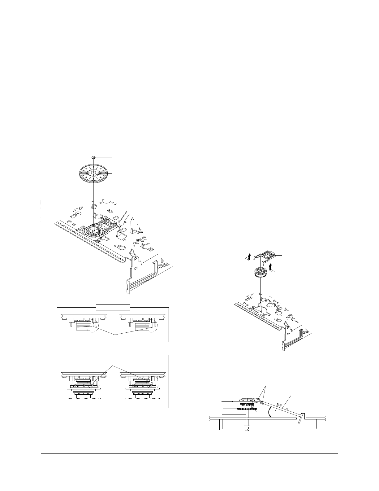
4-2-15 Holder Clutch Ass’y Removal
1) Remove the Washer Slit Œ.
2) Lift the Holder Clutch Ass’y ´.
Note : When you reinstall Holder Clutch Ass'y
1) Check the condition of spring as shown in detail A.
2) Don't push Holder Clutch Ass'y down with excessive force Just insert Holder Clutch Ass'y into post
center with dead force and Rotate it smoothly.
Be sure to confirm that spring is in the slit of Gear
Center Ass'y as shown in detail B.
ΠWASHER SLIT
´ HOLDER CLUTCH ASS`Y
<BAD>
<GOOD>
<BAD>
<GOOD>
SPRING
SPRING
DETAIL A
DETAIL B
Fig. 4-20 Holder Clutch Ass’y Removal
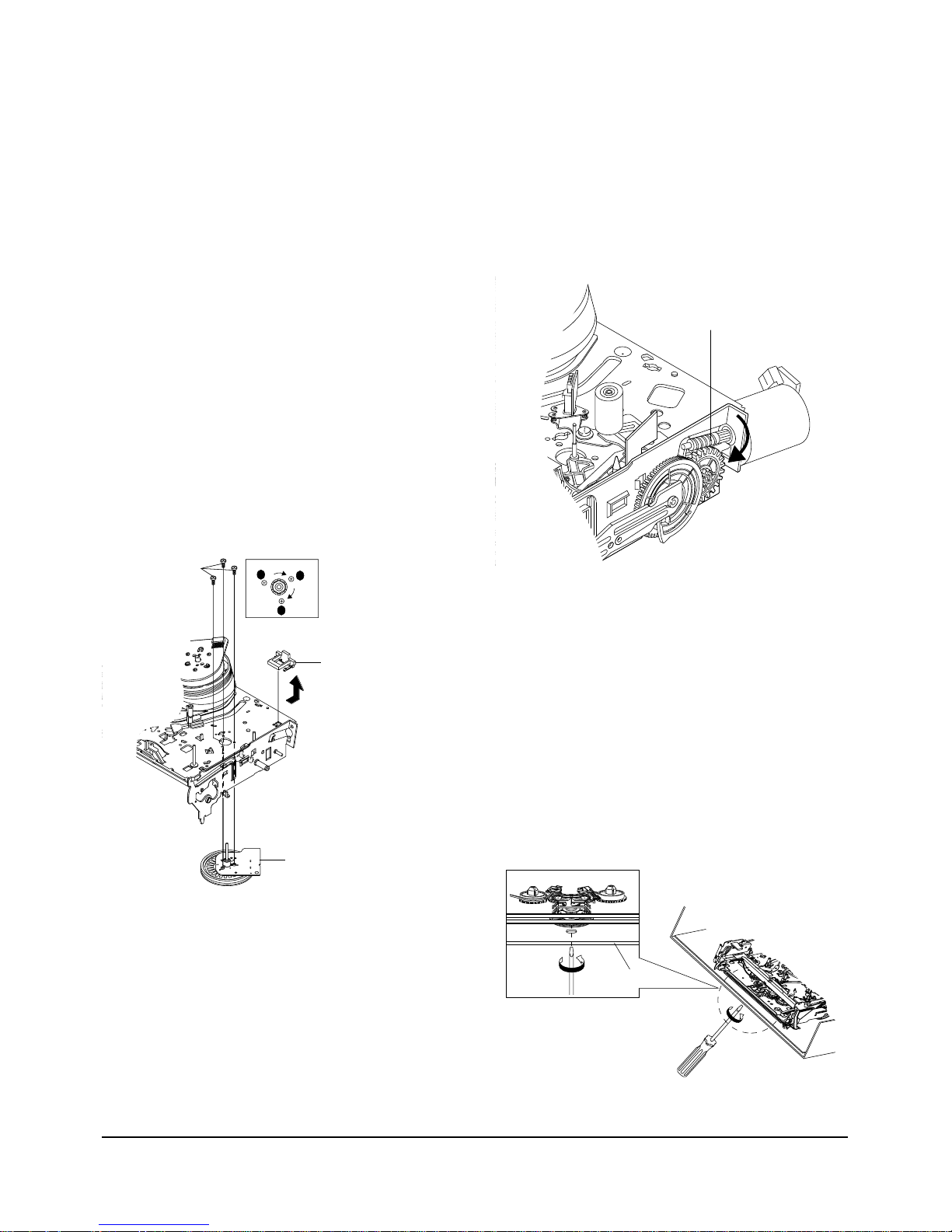
4-2-16 Lever Up Down Ass’y, Gear Center
Ass’y Removal
1)
Remove the 2 hooks in the direction of arrow as
shown Fig. 4-21 and lift the Lever Up Down Ass’y
Œ.
2) Lift the Gear Center Ass’y ´.
Assembly :
1) Insert the Lever Up Down Ass'y Πin the rectangular holes on Main Base as shown in Fig 4-22.
2) Lift the Lever Up Down Ass'y Œ about 35°.
(Refer to Fig 4-22)
3) Insert Ring of the Gear Center Ass'y ´ in the
Guide of the Lever Up Down Ass'y Œ.
4) Insert the Gear Center Ass'y ´ in the post on
Main Base.
5) Push down the Lever Up Down Ass'y Πfor
locking of the Hook.
Note :
1) Take care not to separate and sentence does not
mark sense.
2) Be sure to confirm that Ring of the Gear Center
Ass'y ´ is in the Guide of the Lever Up Down
Ass'y Πafter finishing assembly of Lever Up
Down Ass'y Œ and Gear Center Ass'y ´.
ΠLEVER UP DOWN ASS`Y
´ GEAR CENTER ASS`Y
MAIN BASE
LEVER UP DOWN ASS'Y
GUIDE
GEAR CENTER ASS'Y
RING
GEAR
POST
HOOK
35
Fig. 4-21 Lever Up Down Ass’y Removal
Fig. 4-22 Lever Up Down Ass’y Removal
4-12
Samsung Electronics
Disassembly and Reassembly
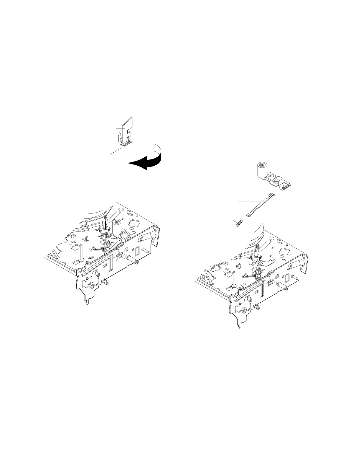
ΠGUIDE CASSETTE DOOR
HOOK [A]
4-2-18 Lever Unit Pinch Ass’y, Plate Joint,
Spring Pinch Drive Removal
1) Lift the Unit Pinch Ass’y Œ.
2) Remove the Plate Joint ´ from Lever Pinch Drive.
3) Remove the Spring Pinch Drive ˇ.
Note :
1) Take extreme care not to touch the grease on the
Roller Pinch.
2) When reinstalling, be sure to apply grease on the
post pinch roller.
ˇ SPRING PINCH DRIVE
ΠLEVER UNIT PINCH ASS`Y
´ PLATE JOINT
Fig. 4-23 Guide Cassette Door Removal
Fig. 4-24 Lever Unit Pinch Ass’y, Plate Joint,
Spring Pinch Drive Removal
4-2-17 Guide Cassette Door Removal
1) Lift the Hook [A].
2) Rotate the Guide Cassette Door Πin the direction
of arrow.
Note : After reinstalling the Guide Cassette Door Œ
sure the Hook [A].
Disassembly and Reassembly
Samsung Electronics
4-13
4-2-19 Lever #9 Guide Ass’y Removal
1) Remove the Spring #9 Guide Œ.
2) Lift the Spring #9 Guide Ass’y ´ in the direction
of arrow “A”.
Note :
1) Take extreme care not to get grease on the tape
Guide Post.
2) After reinstalling, check the bottom side of the Post
#9 Guide to the top side of Main Base.
ΠSPRING #9 GUIDE
´ LEVER #9 GUIDE ASS`Y
"A"
"B"
Fig. 4-25 Lever #9 Guide Ass’y Removal
4-2-20 FE Head Removal
1) Remove the screw Œ.
2) Lift the FE Head ´.
ΠFE HEAD
Fig. 4-26 FE Head Removal
4-14
Samsung Electronics
Disassembly and Reassembly
4-2-21 ACE Head Removal
1) Pull out the FPC from connector of ACE Head
Ass’y ´.
2) Remove the screw Œ.
3) Lift the ACE Head Ass’y ´.
ΠSCREW
´ HEAD ACE ASS`Y
4-2-22 Slider S, T Ass’y Removal
1) Move the Slider S, T Ass’y Œ, ´ to slot, and then
lift it to remove. (Refer to arrow)
ΠSLIDER S ASS`Y
´ SLIDER T ASS`Y
Fig. 4-27 ACE Head Removal
Fig. 4-28 Slider S, T Ass’y Removal
Disassembly and Reassembly
Samsung Electronics
4-15
4-2-23
Plate Ground Deck, Cylinder Ass’y Removal
1) Remove the 3 Screws Œ.
2) Lift the Plate Ground Deck ´.
3) Lift the Cylinder Ass’y ˇ.
Assembly :
1) Match the 3 holes in the bottom of Cylinder ass'y
ˇ to the 3 holes of Main Base as attending not to
drop or knock the Cylinder ass'y ˇ.
2) Tighten the 1 Screw Œ.
3) Match the Plate Ground Deck ´ to the Hole of
Base Main.
4) Tighten the other 2 Screws Œ.
Note :
1) Take care not to touch the Cylinder Ass'y ˇ and
the tape guide post at reinstalling.
2) When reinstalling, Don't push down too much on
Screw Driver.
Π3 SCREWS
´ PLATE GROUND DECK
ˇ CYLINDER ASS'Y
Fig. 4-29 Plate Ground Deck, Cylinder Ass’y Removal
4-2-24 Belt Pulley Removal
1) Remove the Belt Pulley Œ.
Note : Take extreme care not to get grease on Belt
Pulley Πat assembling or reassembling.
ΠBELT PULLEY
Fig. 4-30 Belt Pulley Removal
1-2-25 Level Head Cleaner Ass’y Removal
(Optional)
1) Release the Hook Œ.
2) Lift the Lever Head Cleaner Ass’y
´.
ΠHOOK
´ LEVER HEAD CLEANER ASS'Y
SLEEVE-HEAD CLEANER
Fig. 4-31 Level Head Cleaner Ass’y Removal
4-16
Samsung Electronics
Disassembly and Reassembly
4-2-26 Damper Capstan, Motor Capstan Ass’y
Removal
1) Remove the Damper Capstan Πin the direction
of arrow.
2) Remove the 3 Screws ´.
3) Remove the Motor Capstan Ass’y ˇ.
Assembly :
1) Match the 3 holes of Motor Capstan Ass’y ˇ to the
3 holes of Main Base. Be careful not to drop or
knock the Motor Capstan Ass'y ˇ.
2) Tighten the 3 Screws ´ in the direction of arrow
as shown detail drawing.
3) Assemble the Damper Capstan Œ.
Note : After tightening screws, check if there is gap
between the head of screws and the top side of Main
Base. There should have no gap between the head of
screws and the top side of Main Base.
After reinstalling, adjusting the tape transport
system again.
B
C
A
´ 3 SCREWS
ΠDAMPER CAPSTAN
ˇ MOTOR CAPSTAN ASS'Y
4-2-27 How to Eject the Cassette Tape
(If the unit does not operate on condition that is
inserted into housing ass’y)
1) Turn the Gear worm Πclockwise with screw
driver.(Refer to arrow)
(Other method : Remove the Screw of Motor Load
Ass'y, Separate the Motor Load Ass'y)
ΠGEAR WORM
Fig. 4-32 Damper Capstan,Motor Capstan Ass’y Removal
Fig. 4-33
2) When Slider S,T are approched in the position of
unloading, rotate holder Clutch counterclockwise
after inserting screw driver in the hole of frame's
bottom in order to wind the unwinded tape.
(Refer to Fig.4-34)
(If you rotate Gear Worm Πcontinuously when
tape is in state of unwinding, you may cause a
tape contamination by grease and tape damage.
Be sure to wind the unwinded tape in the state of
set horizently.)
3) Rotate Gear Worm Πclockwise using screw driver
again up to the state of eject mode and then pick
out the tape.(Refer to Fig.4-33)
FRAME
Fig. 4-33
Disassembly and Reassembly
Samsung Electronics
4-17
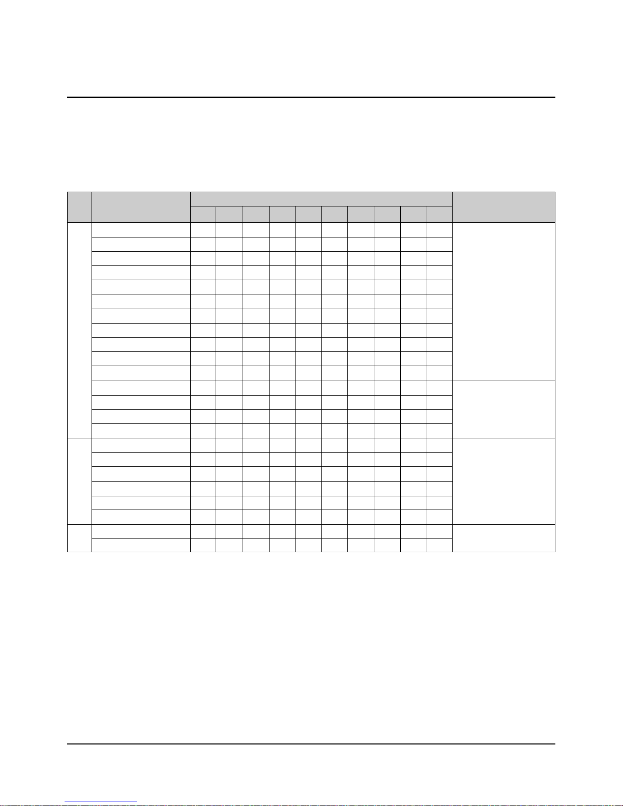
4-3 The table of clearing, Lubrication and replacement time about principal parts
1) The replacement time of parts is not life of parts.
2) The table 1-1 is that the VCR Set is in normal condition (normal temperature, normal humidity).
The checking period may be changed owing to the condition of use, runtime and environmental conditions.
3) Life of the Cylinder Ass’y is depend on the condition of use.
4) See exploded view for location of each parts.
<Table 1-1>
∆ : Cleaning O : Check and replacement in necessary : Add Oil
T
A
PE
P
A
T
H
S
Y
S
T
E
M
D
R
I
V
I
N
G
* Parts Name
Checking Period
Remark
500 1000 1500 2000 2500 3000 3500 4000 4500 5000
POST TENSION ∆∆∆∆∆∆∆∆∆∆
SLANT POST S, T ∆∆∆∆∆∆∆∆∆∆
#8 GUIDE SHAFT ∆∆∆∆∆∆∆∆∆∆
CAPSTAN SHAFT ∆∆∆∆∆∆∆∆∆∆
#9 GUIDE POST ∆∆∆∆∆∆∆∆∆∆
#3 GUIDE POST ∆∆∆∆∆∆∆∆∆∆
GUIDE ROLLER S, T ∆∆∆OOOOOOO
CYLINDER ASS’Y ∆ OOOOOOOOO
FE HEAD ∆∆∆OOOOOOO
ACE HEAD ∆ OOOOOOOOO
PINCH ROLLER ∆ OOOOOOOOO
POST REEL S, T
SLEEVE TENSION
POST CENTER
LEVER IDLE BOSS (2Point)
CAPSTAN MOTOR PULLEY
∆∆∆∆∆OOOOO
BELT PULLEY O O O O O O O
HOLDER CLUTCH ASS’Y
∆ OOOOOOOOO
GEAR CENTER ASS’Y OOOOOOOOO
GEAR IDLE (2Point) O O O O O O O O O
LOADING MOTOR O O O O O O O O O
BAND BRAKE ASS’Y OOOOOOOOO
BRAKE T ASS’Y OOOOOOOOO
S
Y
S
T
E
M
- Periodic time of applying oil (Apply
oil after cleaning)
- The excessive applying oil may be
the cause of
malfunction.
- To clean the parts, use patch and
alcohol (solvent).
- After cleaning, use the video tape
after alcohol is gone away completely.
- We recommend to use oil [EP-50]
or solvent.
- One or two drops of oil should be
applied after
cleaning with alcohol.
B
R
A
K
E
S
Y
S
T
E
M
 Loading...