

Samsung CXJ1352AX, CXJ1331AX, CXJ1964AX, CXJ1364AX, CXJ1952AX Service Manual
...
Television Video Cassette Recorder
Chassis : V15A(REV.2)
Model : CXJ1352AX CXJ1364AX
CXJ1331AX CXJ1931AX
CXJ1952AX CXJ1964AX
Television Video Cassette Recorder CONTENTS
Precautions
Specifications
Alignment and Adjustment (VCR)
Alignment and Adjustment (TV)
Timing Chart
Troubleshooting
Exploded View and Parts List
Electrical Parts List
Block Diagram
Wiring Diagram
Schematic Diagrams
1.
2.
3.
4.
5.
6.
7.
8.
9.
10.
11.

ELECTRONICS
© Samsung Electronics Co., Ltd. JUL. 2000
Printed in Korea
3V15A-1922
1. Precautions
1-1 Safety Precautions
1. Be sure that all of the built-in protective
devices are replaced. Restore any missing
protective shields.
2. When reinstalling the chassis and its
assemblies, be sure to restore all protective
devices, including: nonmetallic control knobs
and compartment covers.
3. Make sure that there are no cabinet openings
through which peopleÑparticularly
childrenÑmight insert fingers and contact
dangerous voltages. Such openings include
the spacing between the picture tube and the
cabinet mask, excessively wide cabinet
ventilation slots, and improperly fitted back
covers.
If the measured resistance is less than 1.0
megohm or greater than 5.2 megohms, an
abnormality exists that must be corrected
before the unit is returned to the customer.
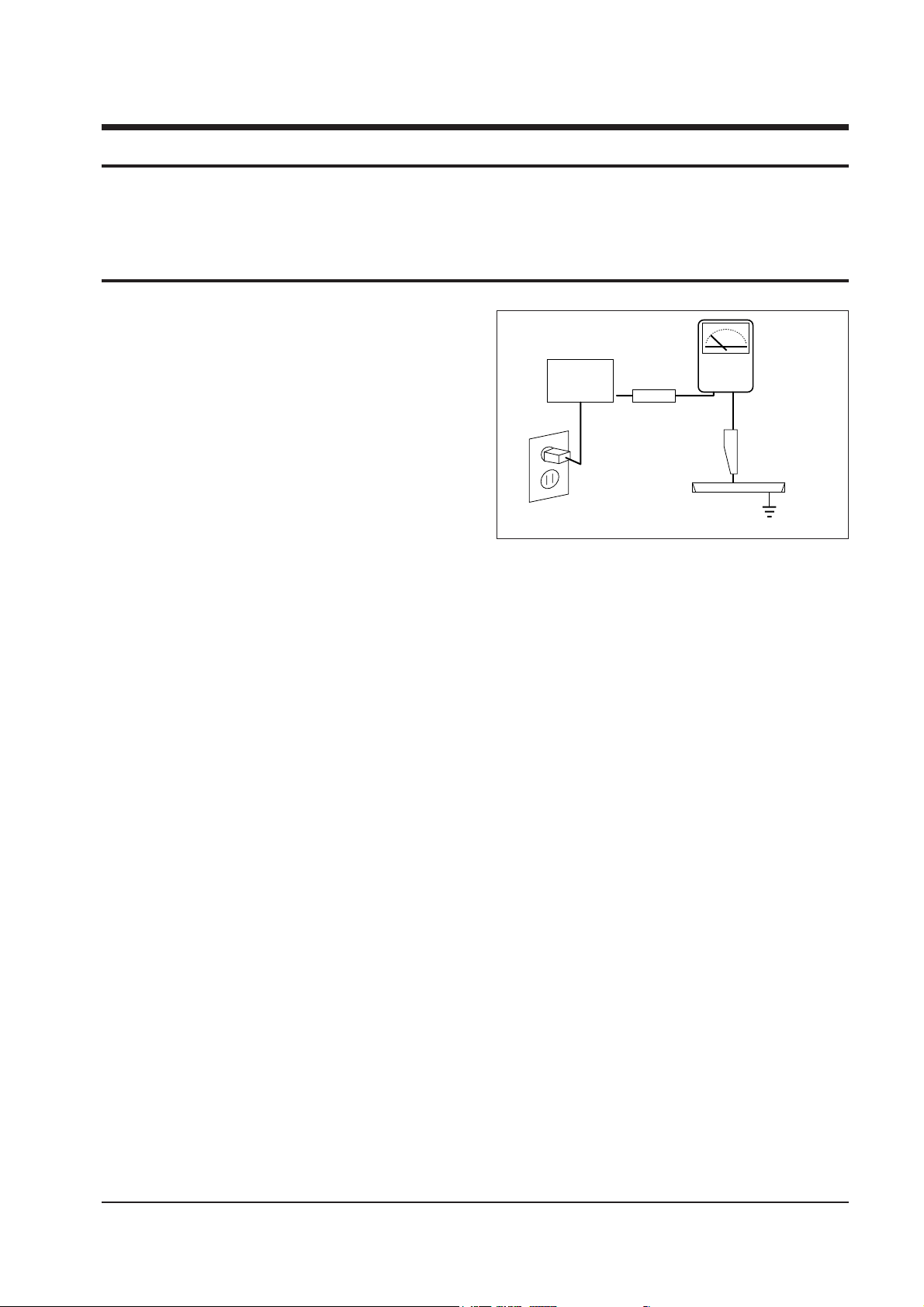
4. Leakage Current Hot Check (Figure 1-1):
Warning: Do not use an isolation
transformer during this test. Use a leakagecurrent tester or a metering system that
complies with American National Standards
Institute (ANIS C101.1, Leakage Current for
Appliances), and Underwriters Laboratories
(UL Publication UL1410, 59.7).
5. With the unit completely reassembled, plug
the AC line cord directly into the power
outlet. With the unitÕs AC switch first in the
ON position and then OFF, measure the
current between a known earth ground (metal
water pipe, conduit, etc.) and all exposed
metal parts, including: antennas, handle
brackets, metal cabinets, screwheads and
control shafts. The current measured should
not exceed 0.5 milliamp. Reverse the powerplug prongs in the AC outlet and repeat the
test.
Fig. 1-1 AC Leakage Test
6. Antenna Cold Check:
With the unitÕs AC plug disconnected from the
AC source, connect an electrical jumper across
the two AC prongs. Connect one lead of the
ohmmeter to an AC prong. Connect the other
lead to the coaxial connector.
7. X-ray Limits:
The picture tube is especially designed to
prohibit X-ray emissions. To ensure continued
X-ray protection, replace the picture tube only
with one that is the same type as the original.
Carefully reinstall the picture tube shields and
mounting hardware; these also provide X-ray
protection.
8. High Voltage Limits:
High voltage must be measured each time
servicing is done on the B+, horizontal
deflection or high voltage circuits. Correct
operation of the X-ray protection circuits must
be
reconfirmed whenever they are serviced.
(X-ray protection circuits also may be called
Òhorizontal disableÓ or Òhold-downÓ.)
Heed the high voltage limits. These include
the XÐray Protection Specifications Label, and
the Product Safety and X-ray Warning Note on
the service data schematic.
Precautions
Samsung Electronics 1-1
LEAKAGE
CURRENT
TESTER
DEVICE
UNDER
TEST
TEST ALL
EXPOSED METAL
SURFACES
2-WIRE CORD
ALSO TEST WITH
PLUG REVERSED
(USING AC ADAPTER
PLUG AS REQUIRED)
EARTH
GROUND
(READING SHOULD
NOT BE ABOVE
0.5mA)
Follow these safety, servicing and ESD precautions to prevent damage and protect against potential
hazards such as electrical shock and X-rays.

1-1 Safety Precautions (Continued)
9. High voltage is maintained within specified
limits by close-tolerance, safety-related
components and adjustments. If the high
voltage exceeds the specified limits, check
each of the special components.
10. Design Alteration Warning:
Never alter or add to the mechanical or
electrical design of this unit. Example: Do not
add auxiliary audio or video connectors. Such
alterations might create a safety hazard. Also,
any design changes or additions will void the
manufacturerÕs warranty.
11. Hot Chassis Warning:
Some TV receiver chassis are electrically
connected directly to one conductor of the AC
power cord. If an isolation transformer is not
used, these units may be safely serviced only
if the AC power plug is inserted so that the
chassis is connected to the ground side of the
AC source.
To confirm that the AC power plug is inserted
correctly, do the following: Using an AC
voltmeter, measure the voltage between the
chassis and a known earth ground. If the
reading is greater than 1.0V, remove the AC
power plug, reverse its polarity and reinsert.
Re-measure the voltage between the chassis
and ground.
12. Some TV chassis are designed to operate with
85 volts AC between chassis and ground,
regardless of the AC plug polarity. These units
can be safely serviced only if an isolation
transformer inserted between the receiver and
the power source.
13. Some TV chassis have a secondary ground
system in addition to the main chassis ground.
This secondary ground system is not
isolated from the AC power line. The two
ground systems are electrically separated by
insulating material that must not be defeated
or altered.
14. Components, parts and wiring that appear to
have overheated or that are otherwise
damaged should be replaced with parts that
meet the original specifications. Always
determine the cause of damage or
overheating, and correct any potential
hazards.
15. Observe the original lead dress, especially
near the following areas: Antenna wiring,
sharp edges, and especially the AC and high
voltage power supplies. Always inspect for
pinched, out-of-place, or frayed wiring. Do
not change the spacing between components
and the printed circuit board. Check the AC
power cord for damage. Make sure that leads
and components do not touch thermally hot
parts.
16. Picture Tube Implosion Warning:
The picture tube in this receiver employs
Òintegral implosionÓ protection. To ensure
continued implosion protection, make sure
that the replacement picture tube is the same
as the original.
17. Do not remove, install or handle the picture
tube without first putting on shatterproof
goggles equipped with side shields. Never
handle the picture tube by its neck. Some
Òin-lineÓ picture tubes are equipped with a
permanently attached deflection yoke; do not
try to remove such Òpermanently attachedÓ
yokes from the picture tube.
18. Product Safety Notice:
Some electrical and mechanical parts have
special safety-related characteristics which
might not be obvious from visual inspection.
These safety features and the protection they
give might be lost if the replacement
component differs from the originalÑeven if
the replacement is rated for higher voltage,
wattage, etc.
Components that are critical for safety are
indicated in the circuit diagram by shading,
( ) or ( ).
Use replacement components that have the
same ratings, especially for flame resistance
and dielectric strength specifications.
A replacement part that does not have the
same safety characteristics as the original
might create shock, fire or other hazards.
Precautions
1-2 Samsung Electronics
!

1-2 Servicing Precautions
1. Servicing precautions are printed on the
cabinet. Follow them.
2. Always unplug the unitÕs AC power cord from
the AC power source before attempting to: (a)
Remove or reinstall any component or
assembly, (b) Disconnect an electrical plug or
connector, (c) Connect a test component in
parallel with an electrolytic capacitor.
3. Some components are raised above the printed
circuit board for safety. An insulation tube or
tape is sometimes used. The internal wiring is
sometimes clamped to prevent contact with
thermally hot components. Reinstall all such
elements to their original position.
4. After servicing, always check that the screws,
components and wiring have been correctly
reinstalled. Make sure that the portion around
the serviced part has not been damaged.
5. Check the insulation between the blades of the
AC plug and accessible conductive parts
(examples: metal panels, input terminals and
earphone jacks).
6. Insulation Checking Procedure: Disconnect the
power cord from the AC source and turn the
power switch ON. Connect an insulation
resistance meter (500V) to the blades of the AC
plug.
The insulation resistance between each blade
of the AC plug and accessible conductive parts
(see above) should be greater than 1 megohm.
7. Never defeat any of the B+ voltage interlocks.
Do not apply AC power to the unit (or any of
its assemblies) unless all solid-state heat sinks
are correctly installed.
8. Always connect a test instrumentÕs ground
lead to the instrument chassis ground before
connecting the positive lead; always remove
the instrumentÕs ground lead last.
Precautions
Samsung Electronics 1-3
Warning 1 : First read the “Safety Precautions” section of this manual. If some unforeseen circumstance creates
a conflict between the servicing and safety precautions, always follow the safety precautions.
Warning 2 : An electrolytic capacitor installed with the wrong polarity might explode.

1. Some semiconductor (Òsolid stateÓ) devices
are easily damaged by static electricity. Such
components are called Electrostatically
Sensitive Devices (ESDs); examples include
integrated circuits and some field-effect
transistors. The following techniques will
reduce the occurrence of component damage
caused by static electricity.
2. Immediately before handling any semicon
ductor components or assemblies, drain the
electrostatic charge from your body by
touching a known earth ground. Alternatively,
wear a discharging wrist-strap device. (Be
sure to remove it prior to applying powerÑ
this is an electric shock precaution.)
3. After removing an ESD-equipped assembly,
place it on a conductive surface such as
aluminum foil to prevent accumulation of
electrostatic charge.
4. Do not use freon-propelled chemicals. These
can generate electrical charges that damage
ESDs.
5. Use only a grounded-tip soldering iron when
soldering or unsoldering ESDs.
6. Use only an anti-static solder removal device.
Many solder removal devices are not rated as
Òanti-staticÓ; these can accumulate sufficient
electrical charge to damage ESDs.
7. Do not remove a replacement ESD from its
protective package until you are ready to
install it. Most replacement ESDs are
packaged with leads that are electrically
shorted together by conductive foam,
aluminum foil or other conductive materials.
8. Immediately before removing the protective
material from the leads of a replacement ESD,
touch the protective material to the chassis or
circuit assembly into which the device will be
installed.
9. Minimize body motions when handling
unpackaged replacement ESDs. Motions such
as brushing clothes together, or lifting a foot
from a carpeted floor can generate enough
static electricity to damage an ESD.
Precautions
1-4 Samsung Electronics
1-3 Precautions for Electrostatically Sensitive Devices (ESDs)
Samsung Electronics 2-1
Specifications
2. Specifications
Format VHS Standard
Recording System Rotary, azimuth two-head or four-head helical scanning system
Luminance : FM azimuth recording
Color signal : converted subcarrier phase shift recording
Television System NTSC-type color signal EIA standard (525 lines, 60 fields)
Audio Track 1 track
Tape Width 12.7 mm (1/2 inch)
SP 33.35 mm/s (1.31 in./s)
SLP 11.12 mm/s (0.43 in./s)
Record/Playback Time 480 min. with T-160 used in SLP mode
FF/Rew Time Less than 100 sec. with T-120
Heads Video : 2 rotary heads, 4 rotary head
Audio/Control : 1 stationary head
Erase : 1 full track erase
1 audio track erase
VIDEO
VIDEO
Input VIDEO IN jack (RCA) 1.0Vp-p, 75 ohm unbalanced
Signal-to-Noise Ratio Better than 35dB
Horizontal Resolution Color/Monochrome: more than 220 lines
AUDIO
AUDIO
Input AUDIO IN jack (RCA) -8dBm,50kohm unbalanced
Horizontal Resolution Color/Monochrome : more than 220 lines
Frequency Response
SP : - 6dB 100Hz - 10KHz
SLP : - 6dB 100Hz - 5KHz
VHF input : Ch.2 - Ch.13, Cable channels 4A, A~W,
W+1~W+84, A-5~A-1
75 ohm unbalanced
UHF input : Ch.14-Ch.69
VHF,UHF one input 75 ohm unbalanced
Power Consumption 13 (14) Inch : Approx. 65 watts when on
19 (20) Inch : Approx. 80 watts when on
Operating Humidity 10%-75%
Operating Temperature 41°F - 104°F (5°C - 40°C)
Power Requirement 120V AC, 60Hz (USA/CANADA), 100V ~ 240V (LATIN)
Equipment specifications are subject to change without notice.
TV Tuner
Record Speed

2-2 Samsung Electronics
MEMO
Alignments and Adjustments (VCR)
Samsung Electronics 3-1
3-1 Mechanical Adjustments
3. Alignments and Adjustments (VCR)
3-1-1 Tape Transport Adjustment
Note : The tape transport system was adjusted precisely in the factory, any adjustments is
unnecessary except for:
✦ Noise on the screen.
✦ Tape damage.
✦ Parts replacement in the tape transport system.
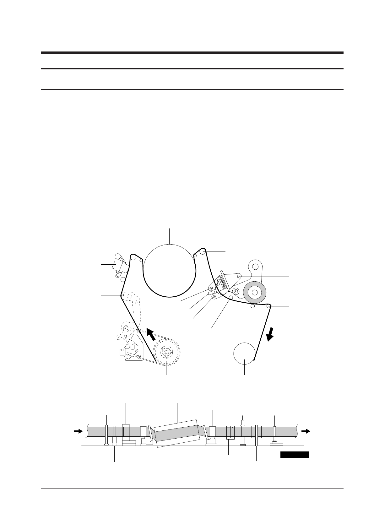
3-1-1(A) PARTS LOCATIONS
The lower flange height of tape guide is used as the reference height for the transport adjustment. To
maintain the height of the tape guide, do not apply excessive force onto the main base.
CYLINDER ASS'Y
TAKE UP REEL DISK
#8 GUIDE POST
#9 GUIDE POST
SUPPLY REEL DISK
CAPSTAN
PINCH ROLLER
GUIDE ROLLER "T"
GUIDE ROLLER "S"
FULL ERASE HEAD
#3 GUIDE POST
TENSION POST
HEIGHT SCREW
TILT SCREW
X - POSITION
ADJUST SILT
AZIMUTH SCREW
Fig. 3-1 Parts Locations of transport system
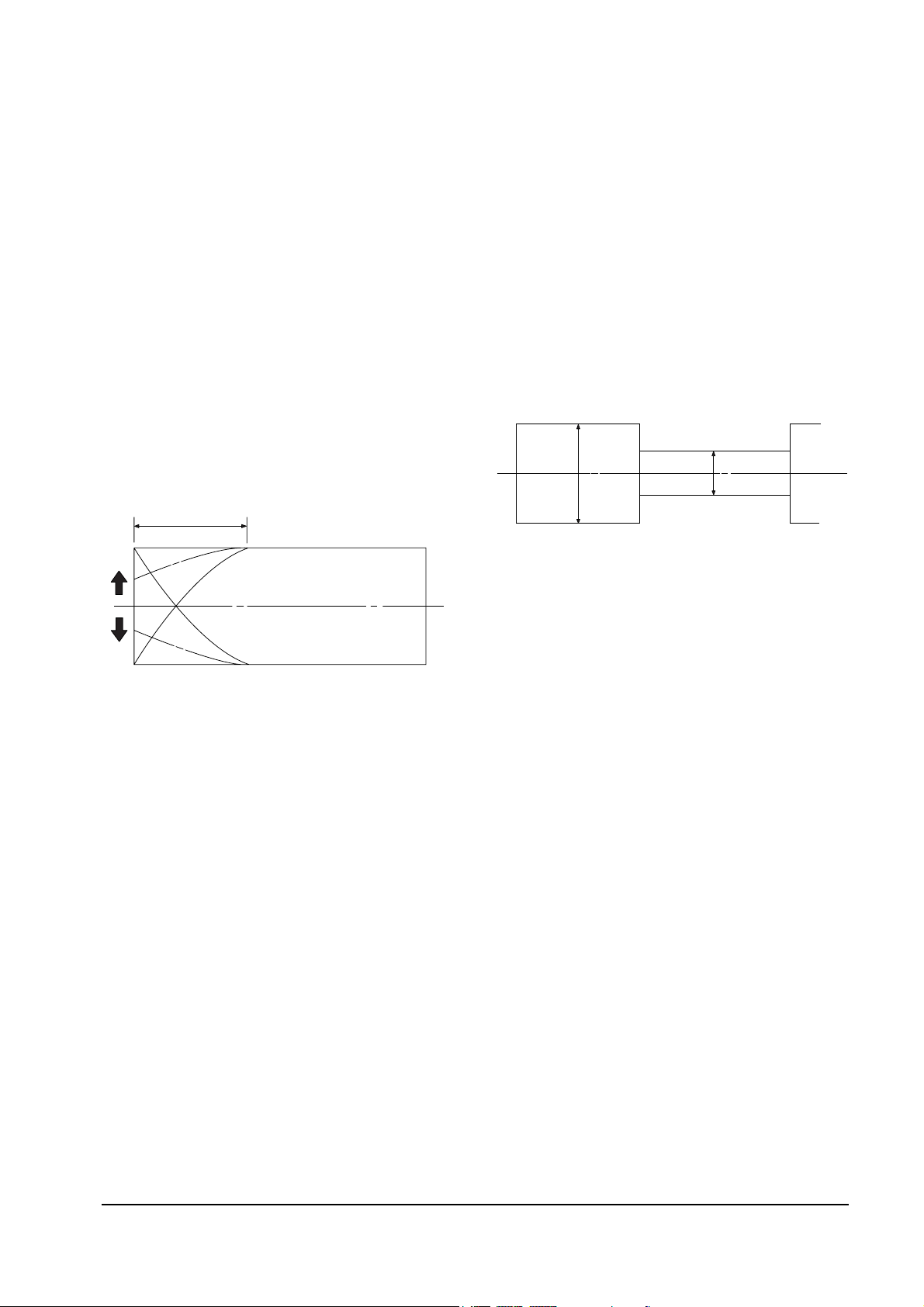
Fig. 3-2 Vertical section of tape transport system
POST TENSION
MAIN BASE
FE HEAD CYLINDER ASS'Y PINCH ROLLER
GUIDE ROLLER "S" GUIDE ROLLER "T"
#8 GUIDE POST #9 GUIDE POST
CAPSTAN SHAFT
ACE HEAD
#3 GUIDE POST
Alignments and Adjustments (VCR)
3-2
Samsung Electronics
Fig. 3-3
3-2 Adjustments
3-2-1 Preadjustment
1. When parts are replaced, the tape ran sport
system may be changed. When many
different parts are replaced, refer to the
procedures for the tape transport system.
To begin run a T-120 tape and make sure that
excessive tape wrinkle does not occur at each
of the tape guides.
2. If tape wrinkle occurs at the S, T-guide rollers,
turn the S, T-guide rollers until the tape
wrinkle disappears.
3. If tape wrinkle still occurs at the tape guide,
adjust the tilt of A/C head.
4. A/C head adjustment locations
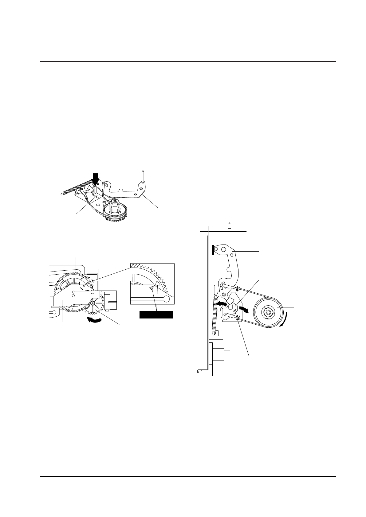
3-2-2 Adjustments
3-2-2(A) A/C HEAD HEIGHT ADJUSTMENT
1. Run the alignment tape (Color bar) in the
playback mode.
2. Observe surface of the audio head using a
dental mirror.
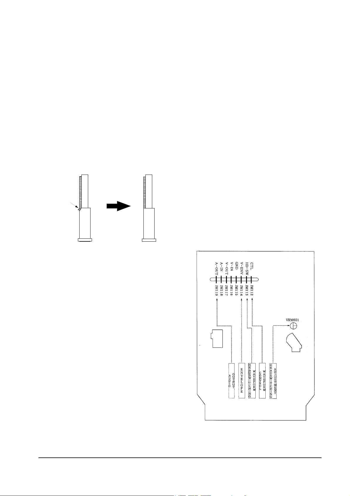
3. Turn screw (C) clockwise or counterclockwise
until the gap of lower tape edge and the lower
edge of the control head is about 0.25mm
(Refer to Fig. 3-4 and 3-5).
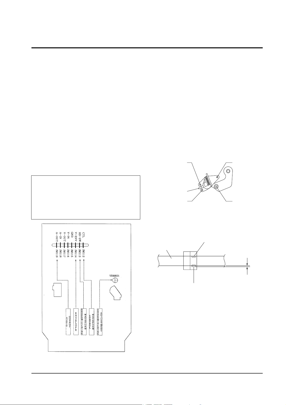
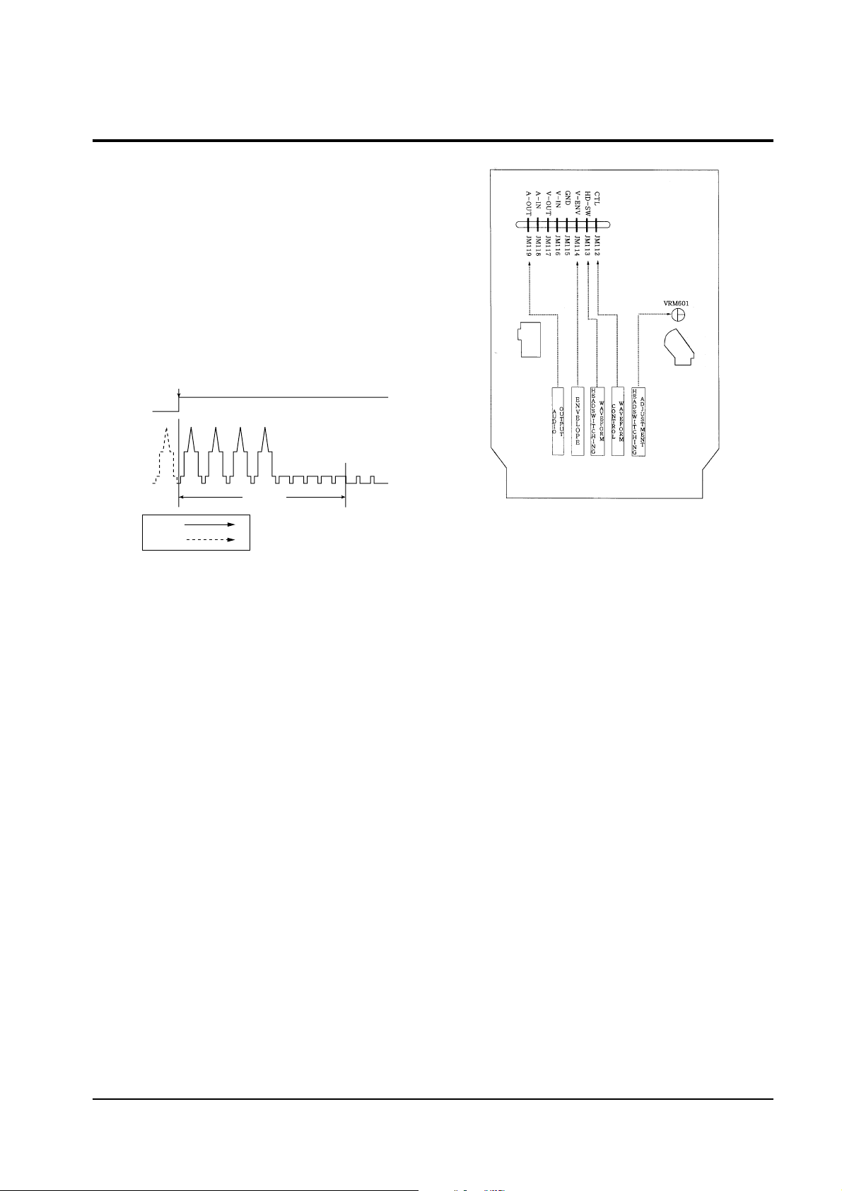
Test Points : JM112-CTL (control waveform)
JM113-H’D SW (head switching sync)
JM114-EnV (envelope waveform)
JM119-A.OUT (audio output)
Test Tape : Color bar (1 KHz)
Lion pattern(7 KHz)
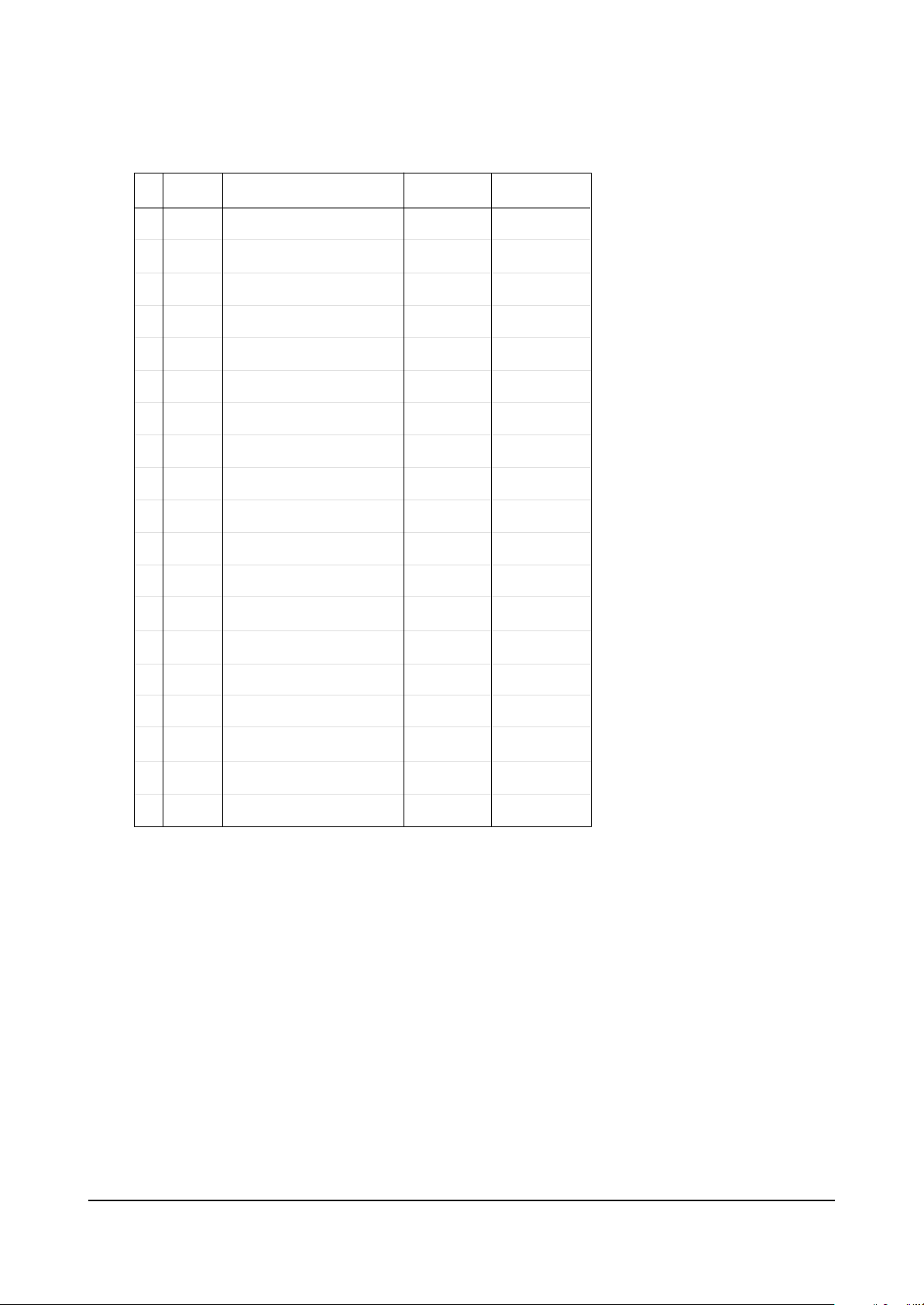
Fig. 3-4 Location of A/C Head Adjustment Screw
SCREW (A)
TLIT ADJUST
X-POSITION
ADJUSTING SLIT
SCREW (C)
HEIGHT ADJUST
SCREW (D)
X-POSITION
LOCKING
SCREW (B)
AZIMUTH ADJUST
Fig. 3-5 A/C Head Height Adjustment
0 ~ 0 .25 mm
AUDIO HEAD
VIDEO HEAD
CONTROL HEAD
Alignments and Adjustments (VCR)
Samsung Electronics 3-3
Fig. 3-7 Test Point Position (Main PCB : Parts)
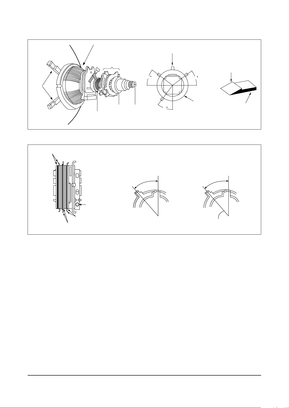
3-2-2 (B) A/C HEAD TILT ADJUSTMENT
1. Playback a blank tape and observe the
position of the tape at the lower flange of tape
guide.
2. Confirm that there is no curl or wrinkle at the
lower flange of tape guide as shown in
(Fig. 3-6).
3. If a curl or wrinkle of the tape occurs, slightly
turn the screw (A) tilt adjust on the ACE head
assÕy.
4. Reconfirm the ACE head height.
3-2-2(D) A/C HEAD POSITION (X-POINT) ADJUSTMENT
1. Load alignment tape (Mono Scope) and play
back a 7KHz signal (SP Mode).
2. Connect Ch1 scope probe to JM119 (A-out),
Ch2 scope probe to JM113-HÕD SW Adjust
sync to Channel 1.
3. 4HD Model : Set the control pulse to 6.5 msec
using the Fine tracking buttons +/- on the
remote control (see Fig. 3-8, 3-9).
2HD Model : 2.5msec (see Fig. 3-8, 3-9).
4. Connect Ch1 scope probe to JM114-ENV.
5. Insert the adjusting driver into the X-position
adjusting gear and adjust the driver for
maximum envelope waveform.
Note :
Do not adjust the X-point using excessive
force. After turning the X-point adjusting
screw (D) counterclockwise a little, perform
the adjustment and then tighten the screw
(See Fig. 3-4).
3-2-2(C) AUDIO AZIMUTH ADJUSTMENT
1. Load alignment tape (Mono Scope) and play
back a 7KHz signal.
2. Connect Ch1 scope probe to JM119(A-OUT).
3. Adjust A/C head azimuth adjustment screw B
for maximum audio output level (see Fig. 3-4).
Fig. 3-6 Tape Guide Check
WRINKLE
(BAD)
(GOOD)
(A)
(B)
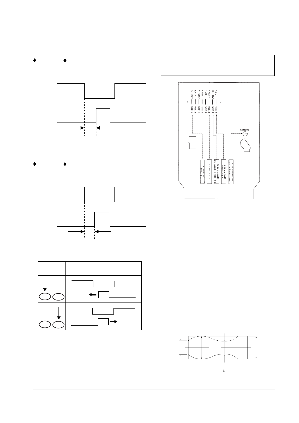
2.5 msec
CH-2 PROBE
H'D SW
PULSE
CH-1 PROBE
CTL PULSE
-Time/div. ; 5 msec
Setting of Scope
- Volt/div. ; CH-1 = 0.1V
CH-2 = 0.2V
6.5 msec
CH-2 PROBE
H'D SW
PULSE
CH-1 PROBE
CTL PULSE
-Time/div. ; 5 msec
Setting of Scope
- Volt/div. ; CH-1 = 0.1V
CH-2 = 0.2V
Alignments and Adjustments (VCR)
3-4
Samsung Electronics
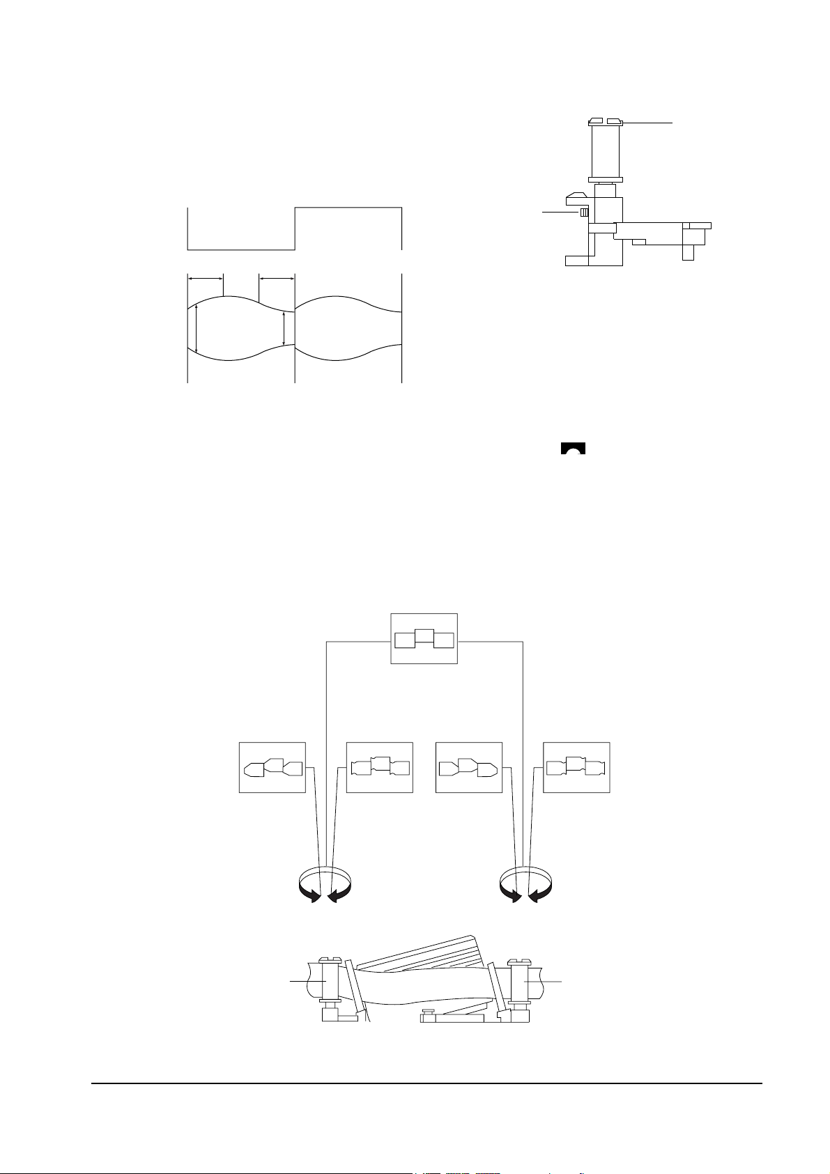
3-2-2(E) LINEARITY ADJUSTMENT
(GUIDE ROLLER S,T ADJUSTMENT)
Fig. 3-8 (A) Tracking Preset Adjustment (4HD)
Fig. 3-8 (B) Tracking Preset Adjustment (2HD)
SCOPE SETTINGS
Fig. 3-9 Control Pulse Adjustment
CONTROL PULSE REMOVE
REMOTE
BUTTONS
_
+
_
+
Fig. 3-10 Test Point Position (Main PCB : Parts)
Test Points : JM113-H’D SW (head switching sync)
JM114-EnV (envelope waveform)
1. Play back the Mono Scope alignment tape (SP
Mode).
2. Observe the video envelope signal on the
oscilloscope after taking sync with the video
switching pulse.
3. Make sure that the video envelope meets the
specifications of Fig. 3-11 (especially for
minimum values).
Note :
a = Maximum output of the video RF envelope
b = Minimum output of the video RF envelope at the
entrance side
c = Minimum output of the video RF envelope at
the center point
d = Maximum output of the video RF envelope at the exit
side
Fig. 3-11 Envelope Waveform Adjustment
a
a b c d
c,b,d/a
63%
bcd
Alignments and Adjustments (VCR)
Samsung Electronics 3-5
4. If Fig. 3-12 A does not meet the specification,
adjust the S-guide roller up or down.
5. If Fig. 3-12 B does no meet the specification,
adjust the T-guide roller up or down.
6. Slightly loosen the set screw at the lower part
of S, T-guide rollers using a hex wrench
(diameter : 0.9mm), so that the guide rollers
can be adjusted with reasonable tightness
(Fig. 3-13).
Fig. 3-12 Adjustment Points
AB
A
B
H'D SWITCHING
PULSE
ENVELOPE
7. Play back the Mono Scope alignment tape (SP
Mode).
8. Connect CH1 to JM114 (ENV), and CH2 to
JM113 (HÕD) for taking sync (located on the
same PCB).
9. Turn the guide roller head with a flat head
screw driver ( ) to obtain a flat video RF
envelope as shown in Fig. 3-14.
10. After completing the adjustments, tighten the
set screw.
Fig. 3-13
SET SCREW
GUIDE ROLLER
Fig. 3-14 S, T-Guide Roller Height Adjustment
IDEAL ENVELOPE
S HEIGHT
TOO HIGH
S HEIGHT
TOO LOW
T HEIGHT
TOO LOW
T HEIGHT
TOO HIGH
GUIDE ROLLER S
GUIDE ROLLER T
Alignments and Adjustments (VCR)
3-6
Samsung Electronics
3-2-3 Check Switch over from RPS to
Playback Mode
1. Check the transition from RPS to playback
mode using a pre-recorded SP tape.
Make sure that the leading edge of envelope
comes to an appropriate steady state within 3
seconds as shown in Fig. 3-15.
2. If the leading edge of envelope waveform
does not meet the specification within 3
seconds, make sure that there is no gap
between the S-roller lower flange and the
tape. If there is a gap, readjust the S-guide
roller.
3 Change operation from RPS to Play back
Mode, and make sure that the leading edge
3-2-4 Envelope Check
1. Make recordings on T-120 and T-160 tapes,
and make sure that the playback output
envelope meets the specification show in Fig.
3-16.
2. Play back a self recorded tape (use a T-120).
The video envelope should meet the
specification shown in Fig. 3-16.
In SLP Mode, (A) should be the same as (B). If
the head gap is wide, check the cylinder
3-2-5 Tape Wrinkle Check
1. Run the T-180 tape in playback, FPS, RPS and
the Pause Modes, and observe the tape
wrinkle at each guide.
2. If excessive tape wrinkle is observed during
the above modes, do the following
adjustments :
If tape wrinkle occurs at S, T-guide rollers, do
a linearity adjustment. If tape wrinkle exists
at the tape guide flange, do an A/C head
assembly adjustment.
Fig. 3-15 Video envelope rise (when transiting from RPS to
Playback mode)
ENTRANCE SIDE ENVELOPE
Fig. 3-16 Envelope Output and Output Level Difference
Playback mode)
A
B

MODE TORQUE g/cm GAUGE
PB
NTSC 82.5 ± 27.5
Cassette Torquemeter
PAL 79 ±27
RPS 145 ± 30
Cassette Torquemeter
Alignments and Adjustments (VCR)
Samsung Electronics 3-7
3-3 Reel Torque Adjustments
1. The rotation of the capstan motor causes the Holder Clutch AssÕy to
rotate through the Belt Pulley.
2. The spring wrap PLAY/REV of holder clutch assÕy drives the disk
reel S, T through gear idle by rotation of gear center assÕy.
3. Brake is operated by slider cam at FF/REW mode.
4. Transportation of accurate driving force is done by gears (Gear Center
AssÕy).
Note : If the spec. does not meet the followings specifications, replace
the holder clutch assÕy and then recheck.
Alignments and Adjustments (VCR)
3-8
Samsung Electronics
4. As rotating Disk S Reel Πclockwise and the
region of adjusting in the Main Base (in shape
of slit) clockwise or counterclockwise after
inserting screw driver in the slit on Main Base.
Adjust the left end edge of Lever Tension
AssÕy ˇ to 1.3+1.5/-0.5mm from the location
of mark in the Main Base.
5. As rotating Disk S Reel Œ, double-check the
location of the left end edge of Lever Tension
AssÕy and the quantity of crossing from mark
on Main Base. (+1.0/-0.5mm)
Counterclockwise : Torque UP
Clockwise : Torque DOWN
Back Tension should be 56 ± 15g.cm at
inspecting it with Back Tension Meter.
1.0mm
0.5mm
ˇ LEVER TENSION ASS'Y
ΠDISK S REEL
´ ADJUSTING
ADJUSTING SLIT
1.3
Fig. 3-19 Tension Pole and Back Tension Adjustment
1. Remove the holder cassette assÕy and then
push the lever FL Arm-R to the direction of
loading.
2. Push the lever tension drive Πin the
direction of arrow. (See Fig. 3-17)
3. Turn the gear worm wheel ´ clockwise so
that ÒTiming PointÓ of the slider FL drive ˇ
and gear FL cam ¨ can be aligned
(See Fig. 3-18).
Fig. 3-17
Fig. 3-18
¨ GEAR FL CAM
´ GEAR WORM WHEEL
ˇ SLIDER FL DRIVE
P
TIMING POINT
ΠLEVER TENSION DRIVE
LEVER TENSION
Note :
1. Mark on Main Base is located in about 1.3mm
from inside of bending line.
2. Be careful not to deform the region of
adjusting on Main Base up and down at
adjusting.
3-4 Location Adjustment and Confirmation of Tension Post
Alignments and Adjustments (VCR)
Samsung Electronics 3-9
3-5-1 Adjust the switching point.
1. Play back the SP standard tape.
2. Connect the oscilloscope CH1 to EYM03 (HÕD)
and CH2 to EYM11 (V.OUT)
3. Set the oscilloscope sync to CH1, and adjust
VRM601 for 6.5H ± 0.5H waveform as shown
in the figure.
3-5 Circuit (SERVO) Adjustment
6.5H 0.5H
+
_
VIDEO
OUTPUT
SWITCHING POINT
SW30Hz
PULSE
Ch2
Ch1
VR
TR
Fig. 3-20
Fig. 3-21

MEMO
3-10
Samsung Electronics
Alignment and Adjustments (TV)
Samsung Electronics 4-1
4. Alignment and Adjustments (TV)
4-1 Factory Alignment
4-1-1 Factory Mode Menus
Since there are no VRs in the V15A chassis, all adjustments must be
performed in the “Factory mode.” Factory Mode adjustments are necessary
if either the EEPROM (IC902) or the CRT is replaced. Do not attempt to
make adjustments in either the Play Mode or Line-in Mode.
4-1-2 Entering the Factory Mode
Press the following transmitter keys in
STANDBY mode:
MUTE → 1 → 8 → 2 → POWER
“Factory Mode Menu” is displayed
10
VCO 45
AGC 45 BC 0
VCO 40 GG 128
SCT 30 BG 128
SCR 20 SB 15
STT 36 VA 36
RC 0 VS 0
GC 0 HS 16
SVC, MUTE
Example for “VCO” : Use the CH down key to select VCO, and use the
Volume + (or VOL - key) to change the data.
PICTURE CONTROL
Alignment and Adjustments (TV)
4-2 Samsung Electronics
4-1-3 Factory Mode Adjustment Settings
Notes:
1. Press MUTE to enter Horizontal Line mode. In this mode, the screen voltage
is checked before adjusting the RGB cut-off.
2. Use Trap On mode to bypass the comb-filter.
3. In the Option mode, adjustments are usually “Analog” (“Digital” is used to
widen the AFT pull-in range).
4. When the VOLUME + key is pressed in the EEPROM mode, all of the “useradjusted” data is reset to the factory-preset values.
5. The ACS/V-CHIP mode is available only in USA and CANADA.
So set ACS/V-CHIP ON only for those two countries.
Initialization
MICOM Data
1
2
3
4
5
6
7
8
9
10
11
12
13
14
15
16
17
18
19
AGC
VCO
SCT
SCR
STT
RC
GC
BC
GG
BG
SB
VA
VS
HS
AFN
ACS/VCHIP
TRAP
OPTION
EEPROM
RF AGC Adjustment
PIF VCO Adjustment
SUB-CONTRAST Adjustment
SUB-COLOR Adjustment
SUB-TINT Adjustment
RED-CUT OFF Adjustment
GREEN-CUT OFF Adjustment
BLUE-CUT OFF Adjustment
GREEN-GAIN Adjustment
BLUE-GAIN Adjustment
SUB-BRIGHTNESS Adjustment
VERTICAL SIZE Adjustment
VERTICAL CENTER Adjustment
HORIZONTAL Phase Adjustment
3.58MHz Switch
AFT Adjustment
User Mode Initialization
No
Item
Function
Range
0 ~ 63
0 ~ 127
0 ~ 63
0 ~ 63
0 ~ 63
0 ~ 255
0 ~ 255
0 ~ 255
0 ~ 255
0 ~ 255
0 ~ 63
0 ~ 63
0 ~ 4
0 ~ 31
ON or OFF
ON or OFF
ON or OFF
ANALOG/DIGITAL
INITIALIZE
45
40
30
20
36
0
0
0
128
128
15
36
0
16
OFF
OFF
ON
ANALOG
INITIALIZE

Alignment and Adjustments (TV)
Samsung Electronics 4-3
4-1-9 White Balance Adjustment
4-1-9 (A) LOW-LIGHT ADJUSTMENTS
1. Input either a lion head or “pure white” color
pattern.
2. Warm up the receiver for 30 minutes.
3. Check data in the Factory mode:
RC, GC, BC should be “0”.
Steps BG and GG should be 128.
4. Enter Horizontal Line mode by pressing the
MUTE key.
5. Adjust the screen VR on T444 (FBT) until a
dim colored line (red,green or blue) appears
on the screen.
6. Adjust RC, BC, GC so that the dim colored
line becomes white.
7. Exit the horizontal line via the MUTE key.
4-1-9 (B) HIGH-LIGHT ADJUSTMENTS
1. After adjusting the low-light,
input a high-light pattern.
2. Adjust GG, BG in the Factory Mode.
3. Recheck in low-light.
4-1-4 IC902 Replacement
1. When IC902 is replaced, all values are reset to
“Initialized MICOM Data,” so readjustment is
necessary.
2. Press the POWER button 10 seconds after
plug-in.
3. To enter the factory mode, refer to 4-1-2
(Factory Mode Adjustment).
4-1-5 PIF VCO Adjustment
1. Without connecting an antenna to the tuner,
feed a 45.75MHz signal to C104. Use a
pattern generator (Marked : ).
2. Adjust the VCO in the service mode; set IC200
Pin 44 (AFT) to 2.5V.
4-1-6 Sub-Contrast Adjustment
1. Set sub-contrast to step 36 (13 inch) or step 40
(19 inch).
4-1-7 Sub-Contrast Adjustment
1. Set sub-tint to step 27.
4-1-8 Sub-Color Adjustment
1. Set sub-tint to step 5.
IF

Alignment and Adjustments (TV)
4-4 Samsung Electronics
4-1-10 Sub-Brightness Adjustment
1. Input a Toshiba pattern.
2. Warm up the receiver for 10 minutes.
3. Enter the Factory mode. Set SB to the point
where the 6th point is brighter in the gray
scale.
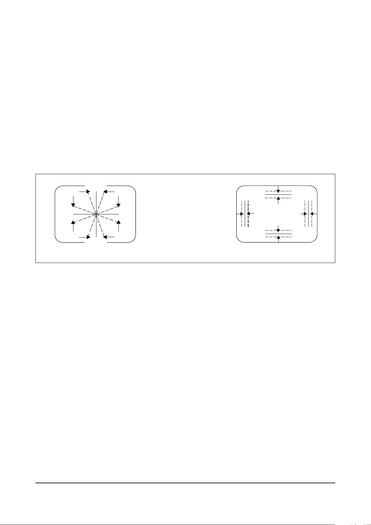
4-1-13 Horizontal Size Adjustment
1. Input a lion head pattern.
2. Enter the Factory mode.
3. Adjust HS so that both left and right
of the pattern are 5.0±0.5.
4-1-14 When CRT Is Replaced
Do the following AFTER the basic purity and
convergence adjustments:
1. White Balance Adjustment
2. Sub-brightness Adjustment
3. Vertical Center Adjustment (VS)
4. Vertical Size Adjustment (VA)
5. Horizontal Size Adjustment (HS)
Notes :
1. After completing all adjustments, press
DISPLAY, 6, 1, 4 and POWER ON while in the
Stand By Mode.
2. Commercial use on/off displays: While the
receiver is off, re-press POWER ON to
restore the adjusted data.
Example 1: If the main power is off while the
receiver is “on” and the receiver is powered
off for a long time, the latest adjusted data
will remain intact when the power is
reapplied.
Example 2: If condition “1”—described
above—occurs while a tape is playing in the
“True Repeat On” mode, the set will revert to
True Repeat when power is reapplied.
Important: Check if the Commercial Use
mode is on. If so, switch it off. Also, it is
impossible to enter the Commercial Mode
when a tape is loaded (i.e., unload the tape
and press DISPLAY, 6, 1, 4, POWER ON).
4. If there is no Toshiba pattern available,
use a 10 step pattern and adjust as follows:
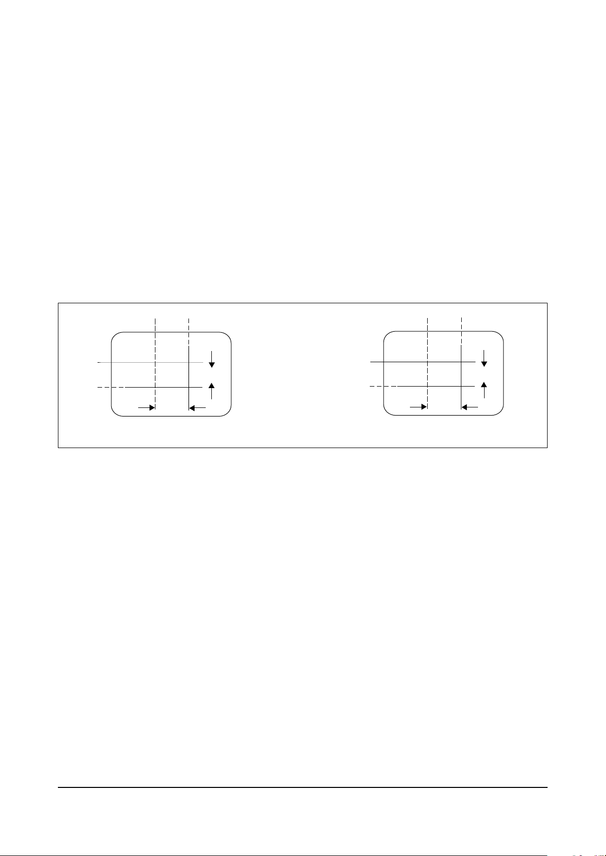
4-1-11 Vertical Center Adjustment
1. Input a lion head pattern.
2. Enter the Factory mode.
3. Set VS so that the vertical center point in the
lion head pattern coincides with the CRT
center.
4-1-12 Vertical Size Adjustment
1. Input a lion head pattern.
2. After the vertical center adjustment, enter the
Factory mode.
3. Adjust VA so that both the top and bottom of
the screen are 3.5. If the top and bottom
values are not equal, adjust so that the sum of
the two values is 7.0.
W
5
4 3
2
1
6
2.5 BLOCKS
BLACK
HALF BLACK
Fig. 4-4

Alignment and Adjustments (TV)
Samsung Electronics 4-5
4-2 Electrical Adjustment
4-2-1 General Alignment Instructions
1. Usually, a color TV-VCR needs only a slight
touch-up adjustment upon installation. Check
the basic characteristics such as picture height,
focus and horizontal and vertical sync.
2. Observe the picture for good black and white
details; there should be no objectionable color
shading. If color shading is present,
demagnetize the receiver. If color shading
persists, perform purity and convergence
adjustments described below.
3. Use the specified test equipment or its
equivalent.
4. Correct impedance matching is essential.
5. Avoid overload. Excessive signal from a
sweep generator might overload the front-end
of the TV. When inserting signal markers, do
not allow the marker generator to distort the
test results.
6. Connect the TV only to an AC power source
with voltage and frequency as specified on the
back-cover nameplate.
7. Do not attempt to connect or disconnect any
wires while the TV is turned on. Make sure
that the power cord is disconnected before
replacing any parts.
8. To protect against shock hazard, use an
isolation transformer.
4-2-2 Fail Safe Circuit Check (FS)
1. The failsafe check must be the final step in
servicing.
2. Turn the power switch ON and adjust
customer controls for normal operation.
3. Temporarily short pin X to pin R on the main
board with a jumper wire. Raster and sound
will disappear.
4. The TV must remain in this state even after
removing the jumper wire. This shows that
the failsafe circuit is working properly.
5. To recover picture and sound, temporarily
turn off the TV and allow the failsafe circuit
more than 30 seconds to reset; switch power
ON to restore normal picture and sound.
4-2-3 Focus Adjustment
Adjust the focus control (T444) for well
defined scanning lines on the picture screen.
4-2-4 High Voltage Check
Caution: There is no high voltage adjustment
on this chassis. The B+ power supply (+125
volts) must be checked to ensure the correct
high voltage. The check point is the D807
cathode.
1. Connect a digital voltmeter to the second
anode of the picture tube.
2. Turn on the TV. Set the Brightness and
Contrast controls to minimum (zero beam
current).
3. The high voltage should be about 24KV.
4. Rotate the Brightness control to both extremes.
Ensure that the high voltage does not exceed
the 30KV limit under any conditions.

Alignment and Adjustments (TV)
4-6 Samsung Electronics
4-2-5 CRT Gray Scale Adjustment
1. Set the Color control to minimum.
2. Adjust the Brightness and Contrast controls
for a low light area.
3. Adjust the Red, Green and Blue Bias controls
to obtain a gray raster of low brightness.
4. Adjust the Brightness and Contrast controls to
maximum.
5. Adjust the Blue Drive and Red Drive controls
for a properly white-balanced picture in high
light areas.
6. Repeat steps 2 through 5 for correct gray
scale.
4-2-6 Automatic Degaussing
A degaussing coil is mounted around the
picture tube. External degaussing after
moving the TV should be unnecessary, but the
receiver must be properly degaussed upon
installation.
The degaussing coil operates for about 1
second after the power is switched ON. If the
set is moved or turned in a different direction,
the power should be OFF for at least 10
minutes.
If the chassis or parts of the cabinet become
magnetized, poor color purity will result; if
this condition occurs, use an external
degaussing coil. Slowly move the degaussing
coil all around receiver, including its faceplate,
picture tube, sides and front. Slowly
withdraw the coil to a distance of about 6 feet
before turning the TV OFF or disconnecting it
from the AC source.
If color shading still persists, do the following
Color Purity and Convergence adjustments.
4-2-7 Color Purity Adjustment
1. If a magnetic-tape beam bender is mounted on
the neck of the picture tube, replace it with an
adjustable-type (Magnet Assembly) prior to
center-purity and center-convergence
adjustments. Consult the replacement parts
list for the correct part number.
2. Warm up the MVCR for 20 minutes, with
Brightness set to maximum.
3. Fully degauss the receiver. Use an external
degaussing coil.
4. Roughly adjust convergence.
5. Input a black and white signal.
6. Turn the low-light controls (Red and Blue)
fully counterclockwise to obtain a green field.
Adjust the Drive controls for a green field.
7. Loosen the Deflection Yoke clamp screw, and
move the Deflection Yoke as close to the
purity magnet as possible.
8. Loosen the purity magnet clamp. Adjust the
purity magnet to set a vertical green raster
precisely at the center of the screen. Then
tighten the clamp.
9. Slowly move the Deflection Yoke forward, and
adjust it for the best overall green screen.
10. Tighten the Deflection Yoke clamp screw.
11. Produce a blue and red raster. Turn the bias
controls fully clockwise. Ensure that good
purity is obtained on each field.
Alignment and Adjustments (TV)
Samsung Electronics 4-7
RUBBER WEDGES
30
30
LOCATION
DEFLECTION
YOKE
30
RUBBER WEDGE
ADHESIVE
RUBBER
WEDGES
KIT
RUBBER
WEDGES
PURITY AND
CONVERGENCE
MAGNET ASS'Y
CRT
DEFLECTION
YOKE
TAPE
CLOTH
GRASS
(1-3/16")
31 mm
Fig. 4-5 Tube Assembly
2 POLE
PURITY
YOKE
CLAMP
SCREW
6 POLE
CONVERGENCE
4 POLE
CONVERGENCE
ADJUST THE ANGLE
(VERTICAL LINES)
FIXED
ROTATE TWO TABS
AT THE SAME TIME
(HORIZONTAL LINES)
Fig. 4-6 Purity and Convergence Magnets
Alignment and Adjustments (TV)
4-8 Samsung Electronics
4-2-8 Center Convergence Adjustment
1. Before attempting convergence adjustments,
the receiver should be powered on for at least
20 minutes.
2. Input a crosshatch pattern from a color bar
generator.
3. Adjust the Brightness and Contrast controls
for a well defined pattern.
4. Adjust the two tabs of the 4-pole magnets.
Change the angle between the tabs, and
superimpose red and blue vertical lines in the
center area of the picture screen.
5. Next, turn both tabs at the same time. Keep
the angle constant, and superimpose red and
blue horizontal lines at the center of the
screen.
6. Adjust the two tabs of 6-pole magnets.
Superimpose the red/blue lines with the
green. Adjusting the angle affects the
horizontal lines.
7. Repeat adjustments 3, 4 and 5. Because the
4-pole and 6-pole magnets interact, the dot
movement is complex.
RED
BLUE
BLUE
RED
4-Pole Magnet Movement
GREEN
RED/BLUE
RED/BLUE
GREEN
6-Pole Magnet Movement
Fig. 4-7 Center Convergence Adjustment
Alignment and Adjustments (TV)
Samsung Electronics 4-9
1. Tilt the yoke by loosening the clamp screw.
2. Insert a temporary mounting wedge. Do not
remove the cover paper on the adhesive part
of the wedge.
3. Tilt the front of the Deflection Yoke up or
down to obtain the best convergence in
circumference. Push the mounted wedge into
the space between the picture tube and the
yoke. This will hold the yoke temporarily in
place.
4. Place the other wedge into the bottom space
and remove the cover paper.
5. Tilt the front of the yoke right or left to obtain
better convergence in circumference.
4-2-9 Circumference Convergence Adjustment
Incline the Yoke Up (or Down)
B G R
R
G
B
R G B
B
G
R
Incline the Yoke Right (or Left)
B G R
R G B
R
G
B
B
G
R
Fig. 4-8 Circumference Convergence Adjustment

MEMO
4-10 Samsung Electronics
Timing Chart
Samsung Electronics 5-1
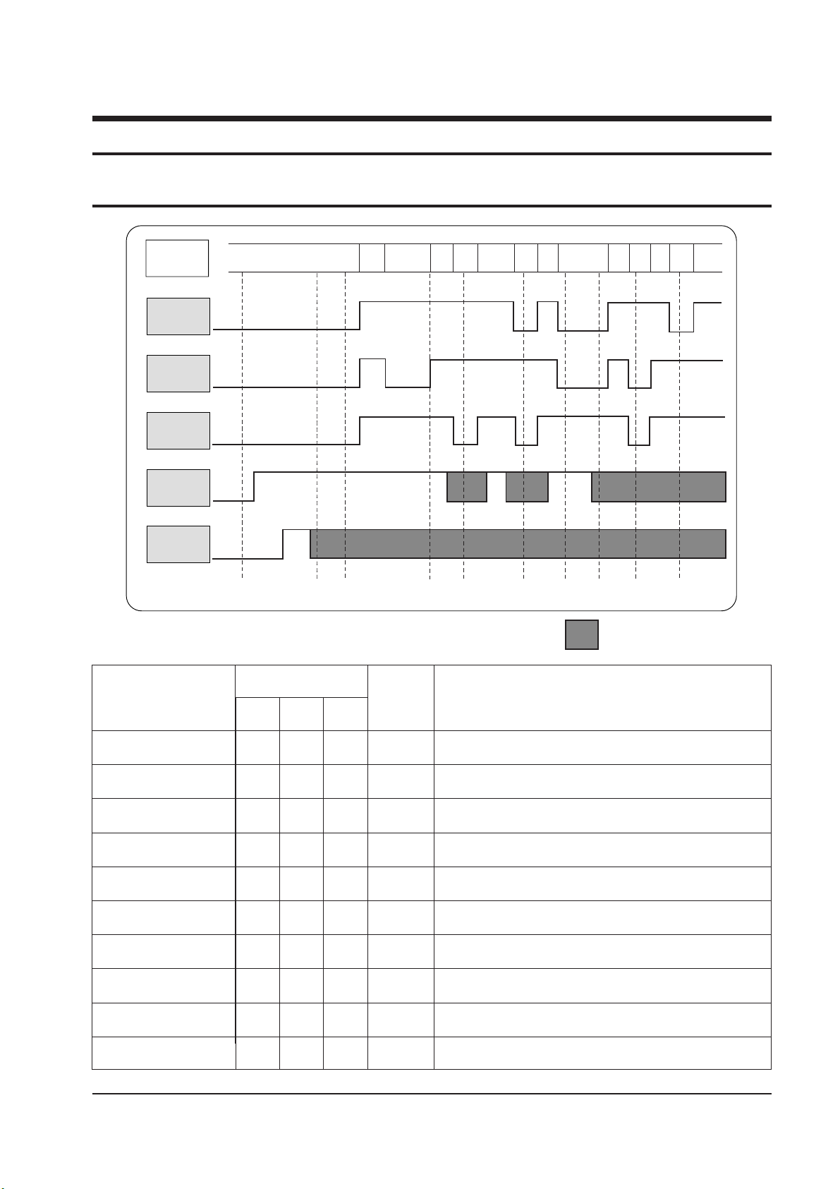
5. Timing Chart
5-1 Program S/W Timing Chart
CAM
POSITION
SW A
SW B
SW C
S/SEN
E/SEN
A
a
B
b
C
c
D
d
E
e
F
f
G
STAND-BY
PWR
OFF
LOAD
START
LOAD
END
REV
PLAY
STP1 STP2
F/R1 F/R2
OFF
OFF
ON
ON
START/END SENSOR : ON - "L", OFF - "H"
: DON'T CARE
0
0
0
1
1
0
0
0
1
0
0
0
0
0 ®1
1
1
0
0
0
1
0
0
0
1
0
0
1
1
0
1
STAND BY
POWER OFF
LOADING START
LOADING END
REV
PLAY
STOP1
STOP2
FF/REV1
FF/REV2
0
1
1
1
X
X
1
X
X
X
Eject
Unload Power Off
(Tape loading start point)
(Tape loading end point)
Reverse Picture Search, Reverse SLOW
Play, Rec, F-PS, Still, SLOW, F-ADV
Stop (Play position 5 Min, over)
(MAIN Break ON MODE)
High speed Rew, Low speed FF
High speed FF, Low speed REW
POSITION
AB
CAM S/W
C
START
SEN
ACTION MODE

MEMO
5-2 Samsung Electronics
 Loading...