

Samsung TSL3295HFX, TSL3295HF, TSL3294HFX, TSL3294HF, TSL2795HFX Owner’s Manual
...
ELECTRONICS
Owner's
Instructions

l Warninq ! Important
Safety Instructions
CAUTION
CAUTION: TO REDUCE THE RISK OF ELECTRIC SHOCK, DO NOT
REMOVE COVER (OR BACK). NO USER SERVICEABLE PARTS INSIDE.
REFER SERVICING TO QUALIFIED SERVICE PERSONNEL.
dangerous to make any kind of contact with any inside part of
This symbol indicates high voltage is present inside, It is
this product.
This symbol alerts you that important literature concerning
operation and maintenance has been included with this producL
Note to CATV system installer: This reminder is provided to call CATV system
installer's attention to Article 820 40 of the National Electrical Code (Section 54 of
Canadian Electrical Code, Part I), that provides guidelines for proper grounding
and, in particular, specifies that the cable ground shall be connected to the
grounding system of the building as close to the point of cable entry as practical.
Caution: FCC/CSA regulations state that any unauthorized ehanges or modillca
tlons to this equipment may void the user's authority to operate it.
Caution: To prevent etectric shoek, match the wide Made of plug to the wide slot,
and fully insert the plug.
Attention: pour eviter les chocs electriques, introduire la lame le ptus large de la
fiche dans la borne correspondante de la prise et pousserjusqu'au fond.
Important: One Federal Court has held that unauthorized recording of
copyrighted TV programs is an infringement of U.S. copyright laws.
Certain Canadian programs may also be copyrighted and any unauthorized
recording in whole or in part may be in violation of these rights.
To prevent damage which may result in fire or electric shock
hazard, do not expose this appliance to rain or moisture.
<Option>
As an ENERGY STAR Partner,
Samstmg Electronics America, Inc. has determined that this product or product
model meets the ENERGY STAR guidelines for energy efficiency
Thank You for Choosing Samsung
Thank you for choosing Samsung! Your new Samsung TV represents the latest in television
technology, We designed it with easy to use on screen menus and closed captioning capabili
ties, makhlg it one of the best products in its class. We are proud to offbr you a product that
will provide convenient, dependable service and enjoyment fur years to come.
Important Safety Information
Always be careful when using your TV receiver. To reduce the risk of fire, electrical shock,
and other injuries, keep these safety precautions in mind when installing, using, and
maintaining your machine.
• Read all safety and operating instructions before operating your T_
• Keep the safety and operating instructions for future re%fence.
• Heed all warnings on the TV receiver and in the operating instructions.
• Follow all operating and use instructions.
• Unplug the TV receiver from the wall outlet befure cleaning. Use a damp cloth; do not use
liquid or aerosol cleaners.
• Never add any attachments and/or equipment without approval of the manufacturer. Such
additions can increase the risk of fire, electric shock, or other personal injury,
• Do not use the TV receiver where contact with or immersion in water is a possibility, such as
near bath tubs, sinks, washing machines, swimming pools, etc.
• Do not place the TV on an unstable cart, stand, tripod, bracket, or
table where it can fail. A falling TV can cause serious injury to a
child or adult, and serious damage to the appliance. Use only with
a cart, stand, tripod, bracket, or table recommended by the manu
facturer or sold with the TV[ Pollow the manufacturer_ instruc
tions when mounting the unit, and use a mounting accessory rec
ommended by the manufacturer. Move the TV and cart with care.
Quick stops, excessive force, and uneven surfaces can make the
unit and cart unsteady and likely to overturn.
• Provide ventilation fur the TV receiver. The unit is designed with
slots in the cabinet for ventilation to protect it from overheating. Do not block these openings
with any object, and do not place the TV receiver on a bed, sofa, rug, or other similar sur
face. Do not place it near a radiator or heat register. If you place the TV receiver on a rack or
bookcase, ensure that there is adequate ventilation and that you've followed the manufactur
er_ instructions fur mounting.
• Operate your TV receiver only from the type of power source indicated on the marking label.
If you are not sure of the type of power supplied to your home, consult your appliance dealer
or local power company
• Use only a grounded or polarized outlet. For your safety, this TV is equipped with a polarized
alternating current line plug having one blade wider than the other. This plug will fit into the
power outlet only one way If you are unable to insert the plug fully into the outlet, try
reversing the plug. If the plug still does not fit, contact your electrician to replace your outlet.
SAFELY
• Protect the power cord. Power supply cords should be routed so that they won't be walked on
or pinched by objects placed on or against them. Pay particular attention to cords at plugs, con
venience receptacles, and the point where they exit from the unit.
• Unplug the TV from the wall outlet and disconnect the antenna or cable system during a light
ning storm or when left unattended and unused for long periods of time. This will prevent dam
age to the unit due to lightning and power line surges.
• Avoid overhead power lines. An outside antenna system should not be placed in the vich]ity of
overhead power lines or other electric light or power circuits or where it can fail into such
power lines or circuits. When installing an outside antenna system, be extremely careful to keep
from touching the power lines or circuits. Contact with such lines can be fatal.
• Do not overload the wall outlet or extension cords. Overloading can result in fire or electric
shock.
• Do not insert anything through the openings in the unit, where they can touch dangerous volt
age points or damage parts. Never spill liquid of any kind on the TV
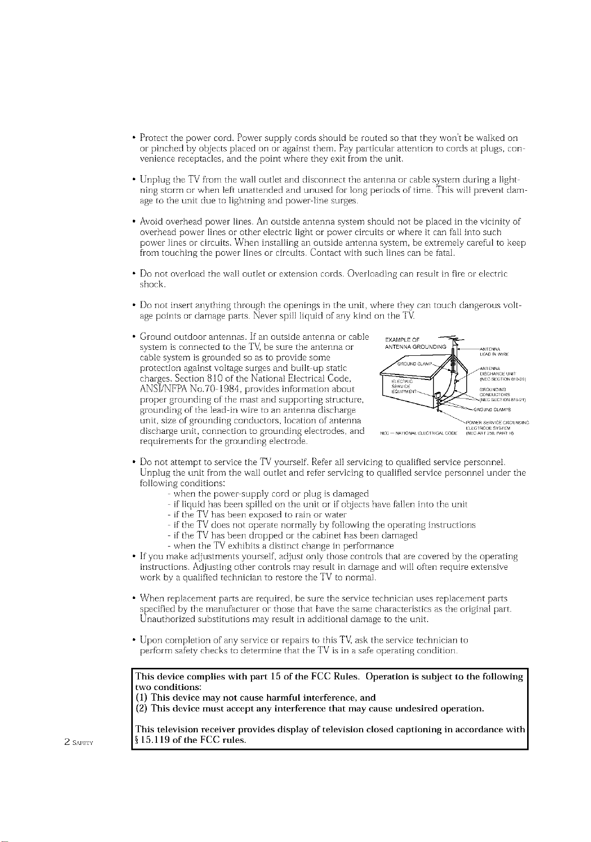
• Ground outdoor antennas. If an outside antenna or cable
system is connected to the TV_be sure the antenna or
EXAMPLEQF
ANTENNAGROUNDING
cable system is grounded so as to provide some
protection against voltage surges and built up static
charges. Section 810 of the National Electrical Code,
ANSI/NFPA No.70 1984, provides infurmation about
proper grounding of the mast and supporting structure,
grounding of the lead in wire to an antenna discharge
unit, size of grounding conductors, location of antenna
discharge unit, connection to grounding electrodes, and
requirements for the grounding electrode.
• Do not attempt to service the TV yourself. Refer all servicing to qualified service personnei.
Unplug the unit from the wall outIet and refer servicing to qualified service personnel under the
fullowing conditions:
when the power supply cord or plug is damaged
if liquid has been spilIed on the unit or if objects have fallen into the unit
if the TV has been exposed to rain or water
if the TV does not operate normally by following the operating instructions
if the TV has been dropped or the cabinet has been damaged
when the TV exhibits a distinct change in performance
• If you make adjustments yourself, adjust only those controls that are covered by the operating
instructions. Adjusting other controls may result in damage and will often require extensive
work by a qualified technician to restore the TV to normal.
• When replacement parts are required, be sure the service technician uses replacement parts
specified by the manufacturer or those that have the same characteristics as the original part.
Unauthorized substitutions may result in additional damage to the unit.
• Upon completion of any service or repairs to this TV] ask the service technician to
perform safety checks to determine that the TV is in a safe operating condition.
This device complies with part 15 of the FCC Rules. Operation is subject to the following
two conditions:
(1) This device may not cause harmful interference, and
(2) This device must accept any interference that may cause undesired operation.
This television receiver provides display of television closed captioning in accordance with
2 s_._ 15.119 of the FCC rules.
CONTENTS ]
Chapter 1: Your New TV ............... 1.1
List of Featuzes ......................................... 1,1
Familiarizing Yuursetf with Yuuz New TV ..................... 1,2
Front Pane[ Buttons .............................. 1,2
Side Panet Jacks ................................. 1,3
Rear Pane[ .Jacks ................................. 1.4
Remote Control ................................. 1.5
Chapter 2: Installation ................ 2.1
Connecting VHF and UHF Antennas ........................ 2.1
Antennas with 300 ohm Flat %vin Leads .............. 2.1
Antennas with 75 ohm Round Leads ................. 2.2
Separate VHF and UHF Antennas .................... 2.2
Connecting Cable TV .................................... 2.2
Connecting a VCR ...................................... 2.,5
Connecting a DVD Player ................................. 2.7
Connecting a Digital TV Set Tup Box ........................ 2.7
Connecting a Surzound Speakers ........................... 2.8
Connecting a Speakezs (Vaziable Autio output) ................. 2.8
Connecting a Camcorder ................................. 2.9
Installing Battezies in the Remote Control ..................... 2.10
Cabte without a Cable Box ......................... 2.2
Connecting to a Cable Box that Desci-amb[es
All Channels .................................... 2.3
Connecting to a Cable Box that Desczamb[es
some Channels .................................. 2.3
Connecting an S VHS VCR......................... 2.6
Connecting a Second VCR to Record from Yuur TV ...... 2.8
1 (]ON] EN] S
Chapter 3: Operation .................. 3.1
Turning the TV On and Off................................ 3.1
Plug & Play Featuze ..................................... 3.1
Viewing the Menus and On Sczeen Displays ................... 3.3
Viewing the Menus ............................... 3.3
Viewing the Display .............................. 3.3
Selecting a Menu Language ................................ 3.4
Memozizing the Channels ................................. 3.5
Selecting the Video Signal source .................... 3.5
Stozing Channels in Memozy (Automatic Method) ....... 3.6
Adding and Ezasing Channels (Manual Method) ........ 3.7
Changing Channels ..................................... 3.7
Using the Channel Buttons ......................... 3.7
Dii-ectly Accessing Channels ........................ 3.7
Using the Pre CH Button to select the PIevious Channel . . 3.7
Adjusting the Vdume .................................... 3.8
Using Mute ..................................... 3.8
Labeling the Channels ................................... 3.9
Setting the Clock ....................................... 3.10
Customizing the Picture .................................. 3.13
Using Automatic Picture Settings ........................... 3. ] 4
Customizing the Sound .................................. 3. ] 5
Using Automatic Sound Settings ............................ 3.16
Viewing a VCR or Camcozdez '.Cape.......................... 3.17
CONTENTS
Chapter 4: Special Features ............ 4.1
Customizing Yuuz Remote ContzoI .......................... 4.1
Setting Up Youz Remote Contzol to Opezate Yuur
VCR (or DVD) .................................. 4.1
Setting Up Youz Remote Contzol to Opezate Yuur
Cable Box...................................... 4.3
Fine Tuning Channels .................................... 4.4
LNA(Low Noise Amplfftez) ................................ 4.5
Digital Noise Reduction .................................. 4.@
Tilt .................................................. 4.7
Changing the Sczeen Size ................................. 4.8
Freezing the Picture ..................................... 4.9
Using the R.surf ........................................ 4.9
Special Sound Options: Dolby Surround, MTS, Auto Vdume and
Headphone ............................................ 4. l0
Dolby Pzo Logic ................................. 4.10
Choosing a Mutti Channel Sound (MTS) Soundtrack ..... 4.11
Adjusting the Headphone Sound .................... 4.12
Auto Volume ..................................... 4.13
Switching the Internal Speakezs On/Off ........................ 4.14
Setting the On/Off Timez ................................. 4.15
Setting the Steep Timer ................................... 4. l@
Viewing Ctosed Captions ................................. 4.17
Viewing Picture in Pictuze ................................ 4.18
Activating Pictuze in Picture ........................ 4.18
Selecting a Signal Source (External A/V) for PIP ......... 4.19
Swapping the Contents of the PIP image and Main image . 4.19
Changing the PIP Charmer ......................... 4.19
Changing the Location (Rotating) the PIP Window ...... 4.19
Changing the Size of the PIP Window ................ 4.19
Scanning the Avaitable Channels .................... 4.19
Using the VChip (Option) ................................ 4.20
Setting Up Youz Pezsonal ID Number (PIN) ............ 4.20
How to Enabte/Disabte the VChip ................... 4.21
How to Set up Restzictions Using the "TV guidelines" . . .. 4.21
How to Set up Restzictions using the MP/\A Ratings:
G, PG, PG 13, R, NC 17, X ........................ 4.23
How to Reset the TV after the VChip Blocks
a Channel ("Emergency Escape") .................... 4.24
Chapter 5: Troubleshooting ............ 5.1
Identifying Pi-oblems .................................... 5.1
Appendix ........................... A.1
Cteaning and Maintaining YuuzTV.......................... A.1
Using Yuuz TV in Anothez Countzy ......................... A.1
Specifications .......................................... A.1
( _H_H_s 2
YOUR NEW TV
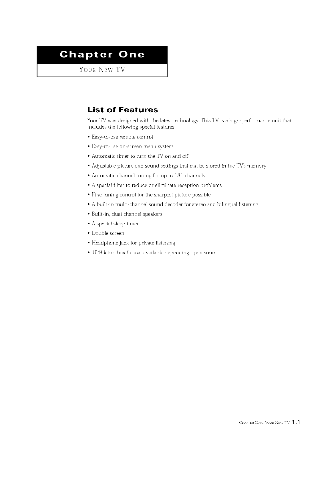
List of Features
Your TV was designed with the latest technology. This TV is a high performance unit that
includes the following special features:
• Easy to use remote control
• Easy tO use on screen _]erlu system
• Automatic timer to turn the TV on and off
• Adjustable picture and sound settings that can be stored in the TV_ memory
• Automatic channel tuning for up to 181 channels
• A special filter to reduce or eliminate reception problems
• Fine tuning control fur the sharpest picture possible
• A built in multi channel sound decoder foF stereo and bilingual listening
• Built in dual channel speakers
• A special sleep timer
• Double screen
• Headphone jack fur private listening
• 16:9 letter box furmat available depending upon sourc
(2HAP] k ON YOll NEW ]V _ .
I Your NEw TV
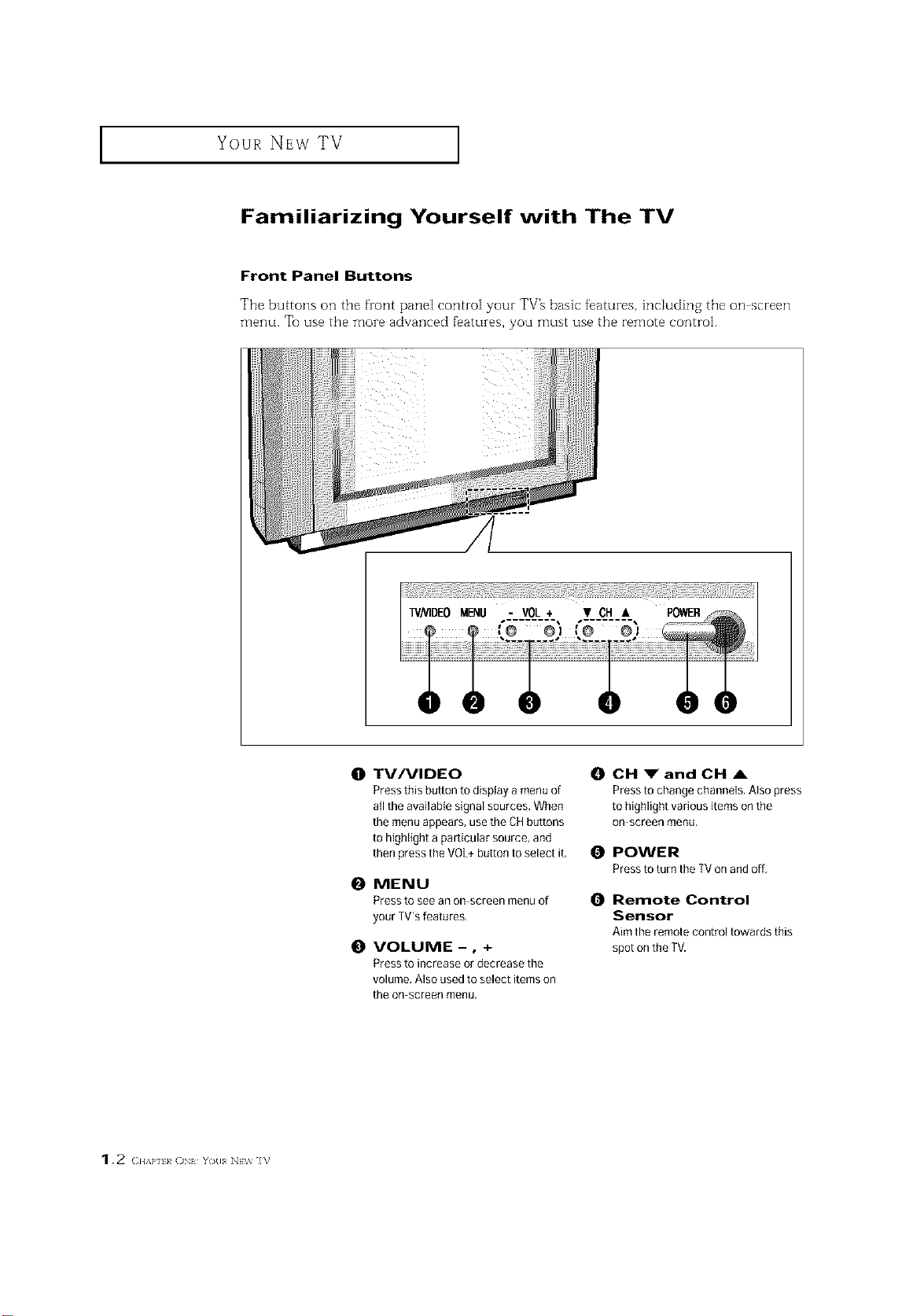
Familiarizing Yourself with The TV
Front Panel Buttons
The buttons on the front pane[ corm-o[ your TV% basic features, includin 8 the on screen
menu. Tu use the more advanced f'eatures, you must use the remote control.
1.2 (2HAP] k ()N YO{I NEV_ IV
0 TV/VIDEO
Press this button to display a menu of
all the available signal sources, When
the menu appears, use the CH buttons
to highlight a particular source, and
then press the VOL+button to select it,
0 MENU
Press to see an on screen menu of
your TVrsfeatures,
0 VOLUME-, +
Press to increase or decrease the
volume, Also used to select items on
the on screen menu.
0 CH _" and CH ,&
Pressto change channels. Atso press
to highlight various items onthe
On screen menu,
0 POWER
Pressto turn the TV on and off,
0 Remote Control
Sensor
Aim the remote control towards this
spot on the TV.
YOUR NEW TV ]
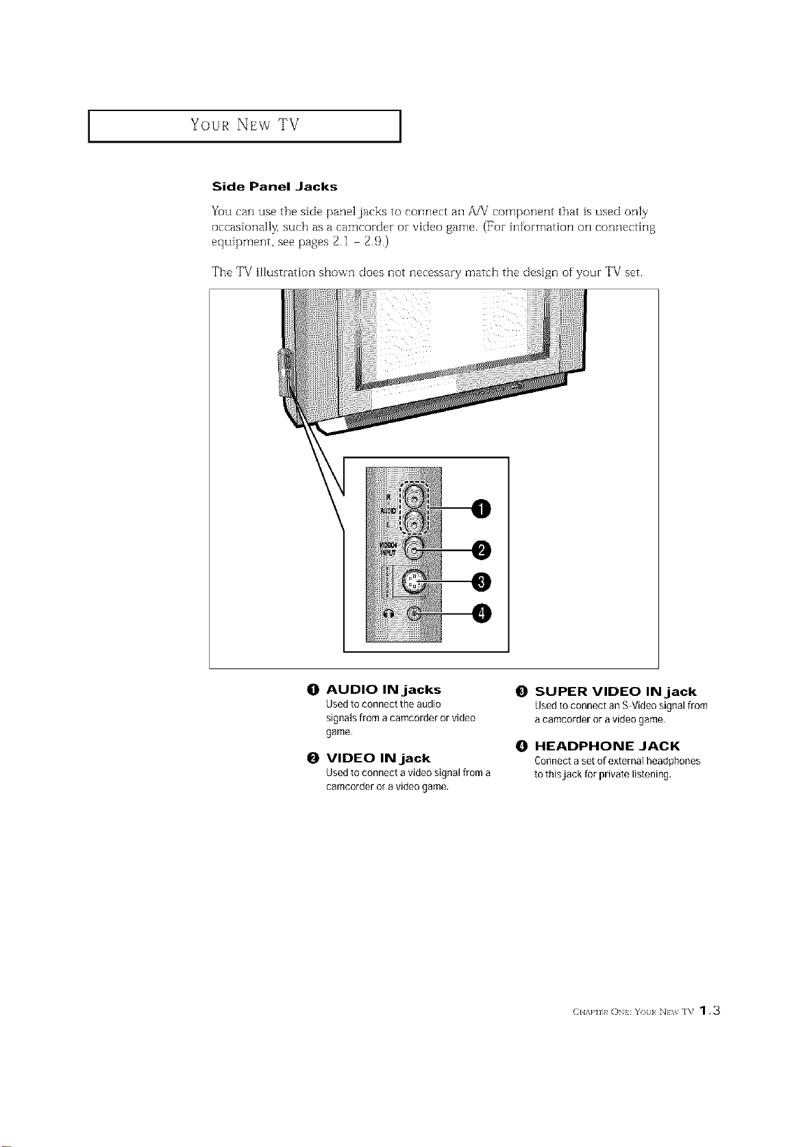
Side Panel Jacks
Yuu can use the side panel jacks to connect an A/V component that is used only
occasionally, such as a camcorder or video game. (For in%rmation on connecting
equipment, see pages 2.1 2.9.)
The TV illustration shown does not necessary match the design of your TV set.
O AUDIO IN jacks
Usedto connect the audio
signals from acamcorder or video
game,
O VIDEO IN jack
Usedto connect a video signal from a
camcorder or a video game.
@
SUPER VIDEO IN jack
Used to connect an S Video signal from
a camcorder or a video game,
O HEADPHONE JACK
Connect aset of external headphones
to thisjack for private listening.
(]HAP] h ON YOll NEV_ IV 1.3
Your NEw TV ]
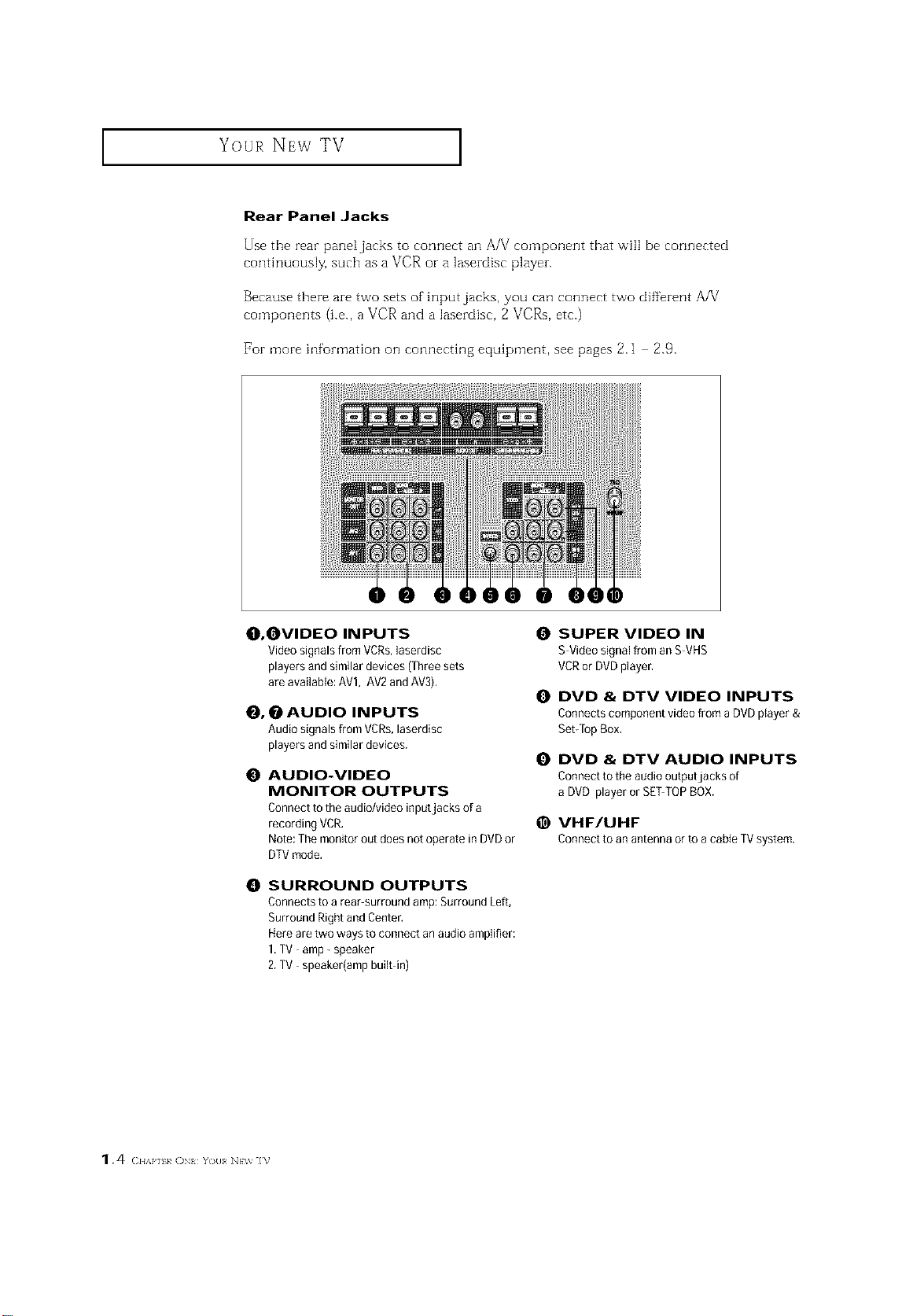
Rear Panel Jacks
Use the rear pane[jacks to connect an A/V component that will be connected
continuously, such as a VCR or a lasezdisc playen
Because there are two sets of input jacks, you can connect two different AA/
components (i.e., a VCR and a lasezdisc, 2 VCRs, etc.)
For more infomlation on connecting equipment, see pages 2.1 2.9.
O, OVIDEO INPUTS
Video signals from VCRs,laserdisc
players and similar devices (Three sets
are availaMe: AVl, AV2 andAV3),
_, _ AUDIO INPUTS
Audio signals from VCRs,laserdisc
players and similar devices.
O AUDIO-VIDEO
MONITOR OUTPUTS
Connect to the audio/video inputjacks of a
recording VCR,
Note:The monitor out does not operate in DVD or
DTVmode,
0 SURROUND OUTPUTS
Connects to a rear surround amp: Surround Left,
Surround Right and Center.
Hereare two ways to connect an audio amplifier:
1,TV amp- speaker
2.TV speaker(amp built in)
SUPER VIDEO IN
S Video signal from an S VHS
VCRor DVDplayer,
O DVD & DTV VIDEO INPUTS
Connects component video from a DVD player &
Set-TopBox,
DVD & DTV AUDIO INPUTS
Connect to the audio outputjacks of
a DVD player or SETTOPBOX.
@ VHF/UHF
Connectto anantennaorto acableTVsystem.
1.4 (2HAP] k ON You NEV_ ]V
Your NEw TV ]
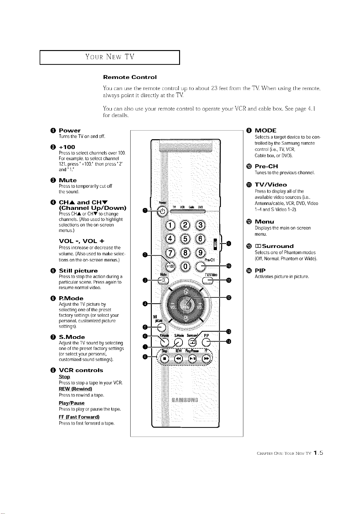
Remote Control
You can use the remote control up to about 23 feet from the TE When using the remote,
always point it directly at the T_
You can also use your remote control to operate your VCR and cable box. See page 4.1
for details.
O Power
Turnsthe TVon and off.
0 +100
Pressto select channels over 100.
For example, to select channel
121,press" +100: then press "2"
and"1 ,"
0 Mute
Pressto temporarily cut off
the sound.
0 OH& and OHm"
(Channel Up/Down)
PressCHA or CHV to change
channels. (Also used to highlight
selections on the on screen
menus,)
VOL -, VOL +
Press increase or decrease the
volume, (Also used to make selec
tions onthe on screen menus.)
0 Still picture
Pressto stop the action during a
particular scene. Press again to
resume normal video.
0 P. Mode
Adjust the TVpicture by
selecting one of the preset
factory settings (or select your
personal, customized picture
settings).
S.Mode
Adjust the TVsound by selecting
oneof the preset factory settings
(orselect your personal
customized sound settings).
0 VCR controls
Stop
Pressto stop a tape in your VCR.
iiiilililililililililil
0
MODE
Selects a target device to be con
trolled by the Samsung remote
control (i,e,,TV,VCR,
Cablebox, or DVD).
@
Pre-CH
Tunestothepreviouschannel
TV/Video
@
Pressto display all of the
available video sources (i.e.,
Antenna/cable, VCR,DVD, Video
1-4 andS Video 1-2).
@
Menu
Displays the main on screen
menu.
@
BOSurround
Selects one of Phantom modes
(Off,Normal, Phantom or Wide).
@ PIP
Activatespictureinpicture,
Pressto rewind a tape,
Pla_/Pause
Pressto playor pause the tape.
FF (Fast Forward)
Pressto fast forward a tape.
(:I{A}'][}/ ()N{ Y()[I N}W ]V 1.5
I Your NEw TV
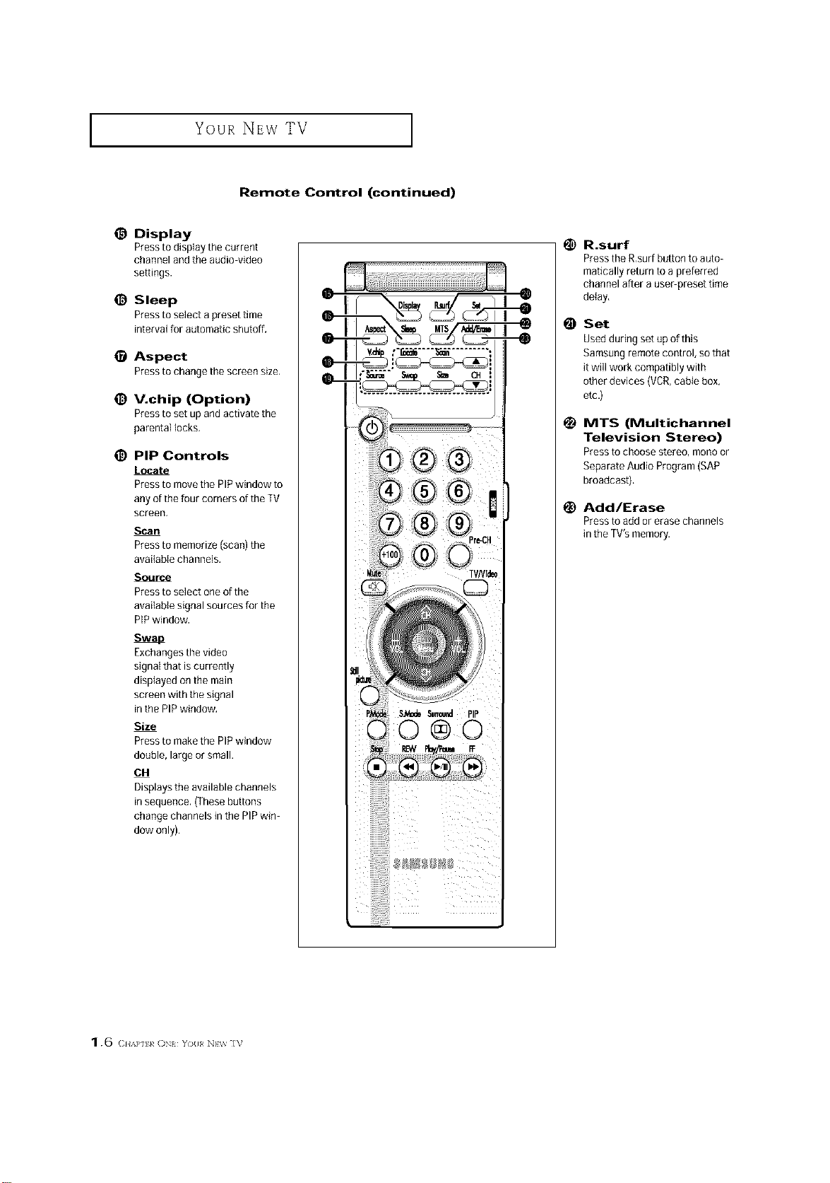
Remote Control (continued)
@ Display
Presstodisp]aythecurrent
channel and the audio video
settings.
@ Sleep
Pressto select a preset time
interval for automatic shutoff,
Aspect
Presstochangethescreensize,
@ V.chip (Option)
Pressto set up and activate the
parental locks,
_) PiP Controls
Locate
Pressto movethe PIPwindow to
any of the four corners of the TV
screen,
Scan
Pressto memorize(scan) the
available channels,
Source
Pressto select one of the
avai{able signal sources for the
PIPwindow.
':....... =.... =-:==J il
il
1_ R.surf
Press the R,surfbutton to auto-
matically return to a preferred
channel after a useepreset time
delay,
Set
Used during set up of this
Samsungremote control, so that
it will work compatibly with
other devices (VCR,cabie box,
etc.)
1_ MTS (Multichannel
Television Stereo)
Press to choose stereo, mono or
Separate Audio Program (SAP
broadcast).
Add/Erase
Press to add or erase channels
in the TV's memory.
Exchangesthe video
signal that is currently
displayed on the main
screen with the signal
in the PIP window.
Size
Pressto makethe PIPwindow
double, large or small.
OH
Displays the available channels
in sequence. (These buttons
change channels in the PIP win
dow only).
1.6 <:.,,},,._ (]N{ Y(_II N}w ]V
INSTALLATION
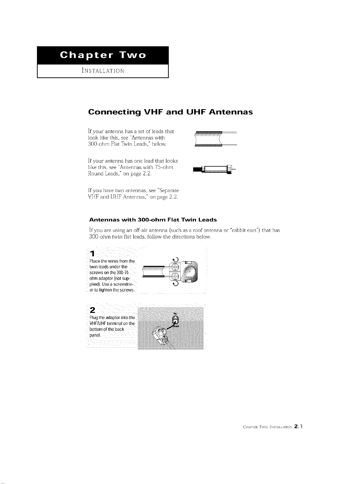
Connecting VHF and UHF Antennas
If your antenna has a set of leads that
look like this, see "Antennas with
300 ohm Flat _vin Leads," below.
If your antenna has one lead that looks
like this, see "Antennas with 75 ohm
Round Leads," oil page 2.2.
If you have two antennas, see "Separate
VHF and UHF Antennas," ollpage 2.2.
Antennas with 300-ohm Flat Twin Leads
If"you are using an offair antenna (such as a roof antenna or "rabbit ears") that has
300-ohm twin flat leads, follow the directions below.
1
r ace the wires from the
[wJn eads under the
screws on the 300_75
ohm aeautor mot su[
ledl Use a screworlv-
er to tighten the screws.
Plug the adaptor into the
bottom of the back
INSTALLATION ]
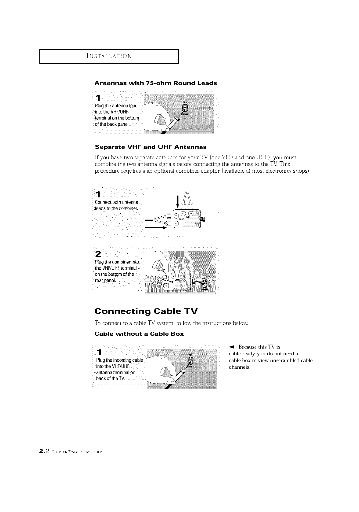
Antennas with 75-ohm Round Leads
1 i
Plugtheantennalead
intotheVHF/UHF
terminalonthebottom
of the back panel.
Separate VHF and UHF Antennas
If you have tvvo separate antennas for your TV (one VHF and one UHF), you must
combine tile two antenna signals before connecting the antennas to tile T_/_This
procedure requiresa an optional combiner adaptor (available at most electronics shops).
Connectbothantenna
leadstothecombiner.
Plugthecombinerinto
theVHF/UHFtermina!
on thebottomofthe
rearpanel
l
Connecting Cable TV
To connect to a cable TV system, foBow tbe instructions below.
Cable without a Cable Box
Because this TV is
cable_ready, you do not need a
Plug the incoming cable cable box to view unscrambled cable
intotheVHF/UHF channels.
antenna terminat 0n
back ofthe IV.
2, 2 < H,',a']l}a J\_o INs],_J] AnON
INSTALLATION ]
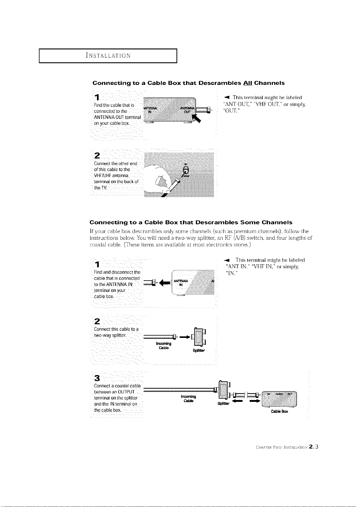
Connecting to a Cable Box that Descrambles All Channels
H
1
Findthe cable that is
connected to the _ _
ANTENNA OUTterminaI
Onyour cable box, ..................' _
Connect the other end
of this cable to the
VHF/UHFantenna
terminal onthe back of
the TV.
-.9 This terminal might be labeled
"ANT OUT," "VI[F OUT," or simply,
"OUT."
Connecting to a Cable Box that Descrambles Some Channels
If"your cable box descrambles only some channels (such as premium channels), fullow the
hlstructions below. You wilI need a two way splitter, an RF (A/B) switch, and fuur lengths of'
coaxial cable. (These items are available at most electronics stores.)
1
Findand disconnect the f
cable that is connected d'totheANTENNA N _ _
terminal or your L _ '
CaD _ DOX
IN
2
Connect this cable [o
two-way spit[tel
Cable
8platmr
3
Connect a coaxial cable
between an OUTPUT
termtnat onthe spmter
and the IN terminal on
the cable box,
InCOming
Cable
--4 This terminal might be labeled
"ANT IN," "VI [F IN," or simply,
"IN."
m
CableBox
(:IIAP] }/ IV() ]NSI%I]AI /IN 2.3
INSTALLATION ]
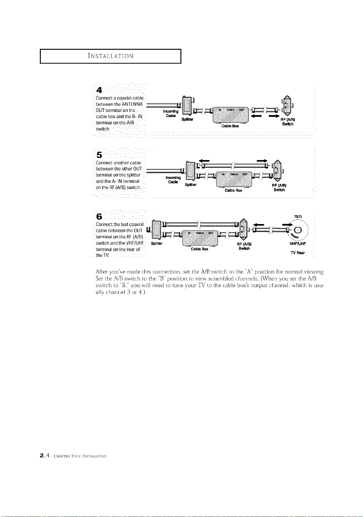
Connect a coaxial cable
OUTterminal 0nthe
between the ANTENNA
cable box andthe B- tN Cable _
terminal onthe A/B Splitter RF(NB)
switch.
Connect another cable
between the other OUT
terminal onthe splitter
and the A* IN terminal
on the RF(A/B)switch,
Incoming
Cable
Splitter
Connect the Iast coaxiaI
cable between the OUT
terminal onthe RF(A/B)
switch and the VHF/UHE Spinier
terminal onthe rear of
Cable Box
the TV.
GableBox Switch
CableBox Switoh
RF(A/B) VHF/UHF
75Q
13/Rear
After you've made this connection, set the A/B switch to the "A" position foz normal viewing.
Set the A/B switch to the "B" position to view scrambled channels. (When you set the A/B
switch to "B," you will need to tune youz TV to the cable box's output channel, which is usu
ally channel 3 or 4.)
2.4 ( ,,A,.,,,_h,o: ]NS,.,,,A,,ON
INSTALLATION ]
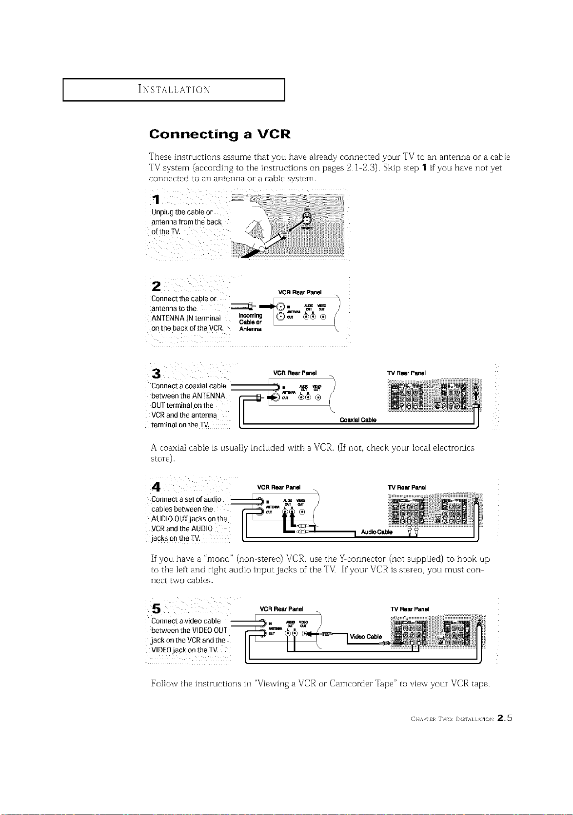
Connecting a VCR
These instructions assume that you have akeady connected youz TV to an antenna oz a cable
TV system (according to the instructions on pages 2.1 2.3). Skip step 1 if you have not yet
connected to an antenna or a cable system.
Connectthecableor / E
VCR Rear Panel
antennatothe _ _II_Q. _ _
ANTENNAINterminat I_ab_, @_ _)_ ®
onthe backoftheVCR. Arr_n_
Connect a coaxial cable
between the ANTENNA
OUTterminal onthe
VCRand the antenna
terminai onthe TM.
A coaxiaI cable is usuaIiy included with a VCR. (If' not, check your local electronics
s[oie).
Connect a set of audio __
cables between the
AUDIOOUTjacks onthe
VCRand the AUDI0
jacks onthe fV.
r L
%
CoaxialCable
VCR Rear Panel TV Rear Panel
l_/RearPanelVCR RearPanel
If'you have a "mono" (non stereo) VCR, use the _connector (not supplied) to hook up
to the left and right audio input jacks of the TV] If'your VCR is stereo, you must con
nect two cables.
VCR Rear Panel TV Rear Panel
Connect a video cable
between the VIDEOOUT
jack on the VCRand the
Video Cable
VIDEOjack on the TV,
[_ollow the instructions in "Viewing a VCR or Camcorder Tape" to view your VCR tape.
(]]]'kl'll l r\_(): INs],_] [,\]l() 2,5
I I
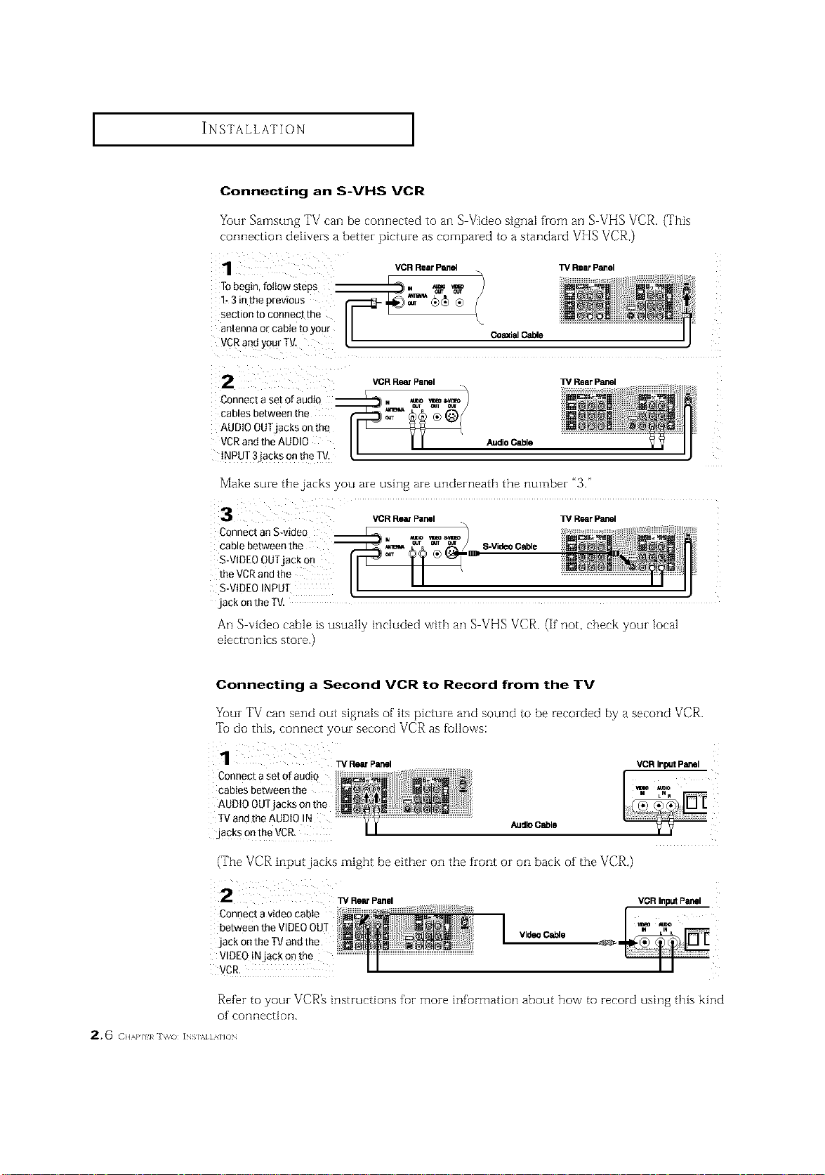
Connecting an S-VHS VCR
Your Samsung TV can be connected to an S Video signal from an S VHS VCR. (This
connection delivers a better picture as compared to a standard VHS VCR.)
VCR Rear Panel ]_ Rear Panel
2
Connect a set ofaudiQ
cables between the
AUDIO OUTjacks on th_
VCRand the AUDIO
iNPUT 3`jackson the TV,
VCR RemPanel TV Rear Panel
Audio Cable
Make sure the jacks you are using are underneath the number "3."
VCRRearPanel W RearPanel
Connect anS-video
cable between the S-VideoCable
S-VIDEOOUTjack on _:
the VCRand the
S-VIDEOINPUT
`jackon the TV.
An S video cable ts usually included vvith all S VHS VCR. (If not, check your Mcal
electronics store.)
Connecting a Second VCR to Record from the TV
Your TV can send out signals of its picture and sound to be recorded by a second VCP,.
Tu do this, connect your second VCR as fullows:
Connecta set ofaudio
cablesbetweenthe
AUDIO OUTjacks on the
TVandthe AUDIO !N AudioCable
,jacksontheVCR.
(The VCR input jacks might be either on the front or on back of the VCR.)
i 2 w RearPanel
Connectavideocable
betweentheVIDEOOUT
.jackontheTVandthe
VIDEOtNjack onthe
VCR.
Refbr to your VCR_ instructions for more information about how to record using this kind
of connection.
2, 6 ( H,,,aq_}_ i_s],v] AHO_
VCR InputPanel
VideoCable
_" !i i
I I ii
INSTALLATION ]
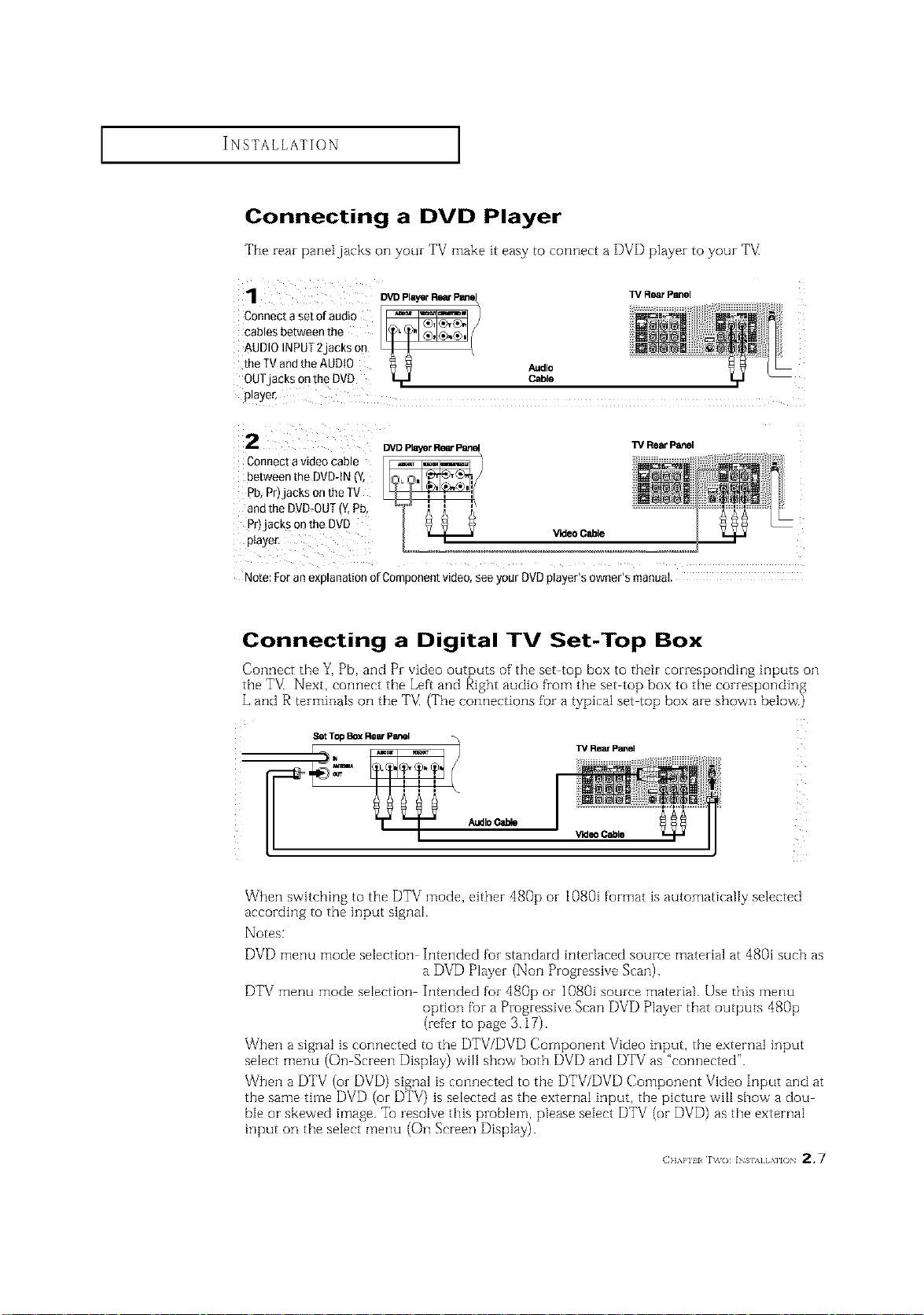
Connecting a DVD Player
The rear paneljacks on your TV make it easy to connect a DVD player to your TM
1
Connect a set of audio
cables between the
AUDIO INPUT 2 laCKSon
the TVand the AUDIO
OUTjacKs on the DVD
p_aye_
2
Connect a video cable
between the DVD-tN _v
_b,Pri acksonthe IV
andthe DVD-OUT{Y.Pb
_r)jacks on the DVD
piayer,
Note: For an exD anation of Comoonent VlCteo,see your DVD player's owner's manual.
_DPlayerRearP_
Audio
Cable
V'KleoCable
W R_rP_el
Rear Panel
Connecting a Digital TV Set-Top Box
Connect the Y, Pb, and Pr video outputs of' the set top box to their corresponding inputs on
the TV_Next, connect the Left and Right audio from the set top box to the corresponding
L and R terminaIs on the TM (The connections for a typical set top box are shown below.)
Set Top Box Rear Panel
TV Rear Panel
AudioCable
When switching to the DTV mode, either dg0p or 1080i format is automatically selected
according to the input signal.
Notes:
_rldeo Cable
DVD menu mode selection Intended for standard interlaced source material at 480i such as
a DVD Player (Non Progressive Scan).
DTV menu mode selection Intended for 480p or 1080i source material. Use this menu
option fur a Progressive Scan DVD Player that outputs 480p
(refer to page 3.17).
When a signal is connected to the DTV/DVD Component Video input, the external input
select menu (On Screen Display) will show both DVD and DTV as "connected".
When a DTV (or DVD) signal is connected to the DTV/DVD Component Video Input and at
the same time DVD (or DTV) is selected as the external input, the picture will show a dou
ble or skewed image. Tel resolve this problem, please select DTV (or DVD) as the external
input on the select menu (On Screen Display).
(]]]'kPlll r\_o: INs],,] [,\]lO 2,7
INSTALLATION ]
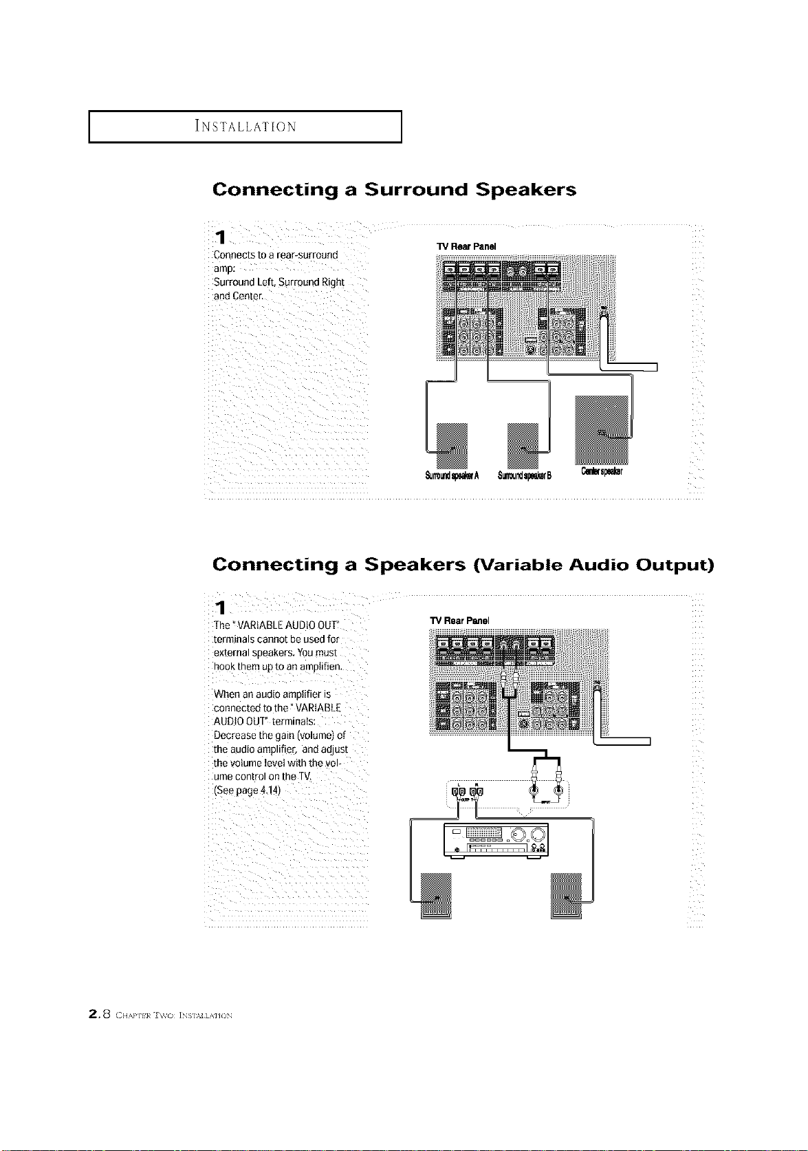
Connecting a Surround Speakers
Connects to a rear-surround
Surround Left, SurrQund Right
W Rear Panel
_Jrmundspem'A 8_Jsp_rB
Connecting a Speakers (Variable Audio Output)
1
The °VARIABLEAUDIO OUT
terminals cannot be usedfor
external soeakers. Youmust
nOOKmere up to an amo(if(en,
TV Rear Panel
When an auo(o amotifier is
connected to the" VARIABLE
AUDIOOUT" terminals
Decrease the _aln IVOlumetOl
me auo(o amolifier, and adjust
me volume level with the vol-
ume con[romon the TV,
(See page4.141
2.8 ( ,,,.,.,.,,,, iNs].%_]AH(3N
 Loading...