

Samsung TNO-4030T, TNO-4030TR, TNO-4050T, TNO-4041TR, TNO-4040TR User Manual

THERMAL
NETWORK CAMERA
User Manual
TNO-4030T/TNO-4040T/TNO-4041T
TNO-4050T/TNO-4051T
TNO-4030TR/TNO-4040TR/TNO-4041TR

Thermal Network Camera
User Manual
Copyright
Hanwha Techwin
©2018
Tra dema rk
Each of trademarks herein is registered. The name of this product and other trademarks mentioned in this manual are the registered trademark of their
respective company.
Restriction
Copyright of this document is reserved. Under no circumstances, this document shall be reproduced, distributed or changed, partially or wholly, without
formal authorization.
Disclaimer
Hanwha Techwin
provided. Use of this document and the subsequent results shall be entirely on the user’s own responsibility.
right to change the contents of this document without prior notice.
Design and specications are subject to change without prior notice.
The initial administrator ID is “admin” and the password should be set when logging in for the rst time.
Please change your password every three months to safely protect personal information and to prevent the damage of the information
theft.
Please, take note that it’s a user’s responsibility for the security and any other problems caused by mismanaging a password.
makes the best to verify the integrity and correctness of the contents in this document, but no formal guarantee shall be
Co., Ltd. All r ights reser ved.
Hanwha Techwin
reserves the

overview
IMPORTANT SAFETY INSTRUCTIONS
1. Read these instructions.
2. Keep these instructions.
3. Heed all warnings.
4. Follow all instructions.
5. Do not use this apparatus near water.
6. Clean the contaminated area on the product surface with a soft, dry cloth or a damp cloth.
(Do not use a detergent or cosmetic products that contain alcohol, solvents or surfactants or oil constituents
as they may deform or cause damage to the product.)
7. Do not block any ventilation openings, Install in accordance with the manufacturer’s instructions.
8. Do not install near any heat sources such as radiators, heat registers, stoves, or other apparatus (including
amplifiers) that produce heat.
9. Do not defeat the safety purpose of the polarized or grounding-type plug. A polarized plug has two blades
with one wider than the other. A grounding type plug has two blades and a third grounding prong. The wide
blade or the third prong are provided for your safety. If the provided plug does not fit into your outlet, consult
an electrician for replacement of the obsolete outlet.
10. Protect the power cord from being walked on or pinched particularly at plugs, convenience receptacles, and
the point where they exit from the apparatus.
11. Only use attachments/ accessories specified by the manufacturer.
12. Use only with the cart, stand, tripod, bracket, or table specified by the manufacturer,
or sold with the apparatus. When a cart is used, use caution when moving the cart/
apparatus combination to avoid injury from tip-over.
13. Unplug this apparatus during lighting storms or when unused for long periods of time.
14. Refer all servicing to qualified service personnel. Servicing is required when the apparatus
has been damaged in any way, such as power-supply cord or plug is damaged, liquid has
been spilled or objects have fallen into the apparatus, the apparatus has been exposed to rain or moisture,
does not operate normally, or has been dropped.
15. This product is intended to be supplied by a Listed Power Supply Unit marked “Class 2” or “LPS” and rated
from 24 Vac (50/60 Hz) min.0.91 A or 12 Vdc, min.0.83 A.
16. If you use excessive force when installing the product, the camera may be damaged and malfunction.
If you forcibly install the product using non-compliant tools, the product may be damaged.
17. Do not install the product in a place where chemical substances or oil mist exists or may be generated. As
edible oils such as soybean oil may damage or warp the product, do not install the product in the kitchen or
near the kitchen table.
This may cause damage to the product.
18. When installing the product, be careful not to allow the surface of the product to be stained with chemical
substance.
Some chemical solvents such as cleaner or adhesives may cause serious damage to the product’s surface.
19. If you install/disassemble the product in a manner that has not been recommended, the production functions/
performance may not be guaranteed.
Install the product by referring to “Installation & connection” in the user manual.
20. Installing or using the product in water can cause serious damage to the product.
WARNING
TO REDUCE THE RISK OF FIRE OR ELECTRIC SHOCK, DO NOT EXPOSE THIS PRODUCT
TO RAIN OR MOISTURE. DO NOT INSERT ANY METALLIC OBJECT THROUGH THE
VENTILATION GRILLS OR OTHER OPENINGS ON THE EQUIPMENT.
Apparatus shall not be exposed to dripping or splashing and that no objects filled with liquids,
such as vases, shall be placed on the apparatus.
To prevent injury, this apparatus must be securely attached to the Wall/ceiling in accordance
with the installation instructions.
CAUTION
CAUTION
RISK OF ELECTRIC SHOCK.
DO NOT OPEN
CAUTION
: TO REDUCE THE RISK OF ELECTRIC SHOCK.
DO NOT REMOVE COVER (OR BACK).
NO USER SERVICEABLE PARTS INSIDE.
REFER SERVICING TO QUALIFIED SERVICE PERSONNEL.
EXPLANATION OF GRAPHICAL SYMBOLS
The lightning flash with arrowhead symbol, within an equilateral triangle, is
intended to alert the user to the presence of “dangerous voltage” within the
product’s enclosure that may be of sufficient magnitude to constitute a risk of
electric shock to persons.
The exclamation point within an equilateral triangle is intended to alert the user to
the presence of important operating and maintenance (servicing) instructions in
the literature accompanying the product.
●● OVERVIEW
English _3

overview
Class construction
An apparatus with CLASS construction shall be connected to a MAINS socket outlet with a
protective earthing connection.
Battery
Batteries(battery pack or batteries installed) shall not be exposed to excessive heat such as
sunshine, fire or the like.
Disconnection Device
Disconnect the main plug from the apparatus, if it’s defected. And please call a repair man in
your location.
When used outside of the U.S., it may be used HAR code with fittings of an approved
agency is employed.
CAUTION
RISK OF EXPLOSION IF BATTERY IS REPLACED BY AN INCORRECT TYPE.
DISPOSE OF USED BATTERIES ACCORDING TO THE INSTRUCTIONS.
ATTENTION
IL Y A RISQUE D’EXPLOSION SI LA BATTERIE EST REMPLACÉE PAR UNE BATTERIE DE
TYPE INCORRECT.
METTRE AU REBUT LES BATTERIES USAGÉES CONFORMÉMENT AUX INSTRUCTIONS.
These servicing instructions are for use by qualified service personnel only.
To reduce the risk of electric shock do not perform any servicing other than that contained in
the operating instructions unless you are qualified to do so.
The CVBS out terminal of the product is provided for easier installation, and is not
recommended for monitoring purposes.
Please use the input power with just one camera and other devices must not be connected.
The ITE is to be connected only to PoE networks without routing to the outside plant.
The wired LAN hub providing power over the Ethernet (PoE) in accordance with IEEE
802-3af shall be a UL Listed device with the output evaluated as a Limited Power Source
as defined in UL60950-1.
Unit is intended for installation in a Network Environment 0 as defined in IEC TR 62102.
As such, associated Ethernet wiring shall be limited to inside the building.
Please read the following recommended safety precautions carefully.
yDo not place this apparatus on an uneven surface.
yDo not install on a surface where it is exposed to direct sunlight, near heating equipment or
heavy cold area.
yDo not place this apparatus near conductive material.
yDo not attempt to service this apparatus yourself.
yDo not place a glass of water on the product.
yDo not install near any magnetic sources.
yDo not block any ventilation openings.
yDo not place heavy items on the product.
yPlease wear protective gloves when installing/removing the camera.
The high temperature of the product surface may cause a burn.
User’s Manual is a guidance book for how to use the products.
The meaning of the symbols are shown below.
yReference : In case of providing information for helping of product’s usages
yNotice : If there’s any possibility to occur any damages for the goods and human caused by
not following the instruction
Please read this manual for the safety before using of goods and keep it in the safe place.
4_ overview

CONTENTS
overview
3
3 Important Safety Instructions
6 Recommended PC Specifications
6 Recommended Micro SD/SDHC/SDXC
Memory Card Specifications
6 NAS recommended specs
7 What’s Included (TNO-4030T/4040T/4050T
/4030TR/4040TR)
8
What’s Included (TNO-4041T/4051T/4041TR)
9
At a Glance (TNO-4030T/4040T/4050T/4030TR
/4040TR)
9 At a Glance (TNO-4041T/4051T/4041TR)
web viewer
24
appendix
25
24 Connecting to the Camera
24 Password setting
24 Login
24 Camera Web Viewer Setup
●● OVERVIEW
25 Specification
29 Product Overview
30 Troubleshooting
31 Open Source Announcement
installation & connection
10
network connection and
setup
18
10 Installation (TNO-4030T/4040T/4050T/
4030TR/4040TR)
11 Installation (TNO-4041T/4051T/4041TR)
13 Inserting/Removing a Micro SD Memory
Card
14 Memory Card Information (Not Included)
14 Connecting with other Device
18 Connecting the Camera Directly to Local
Area Networking
18 Connecting the Camera Directly to a DHCP
Based DSL/Cable Modem
19 Connecting the Camera Directly to a
PPPoE Modem
19 Connecting the Camera to a Broadband
Router with the PPPoE/Cable Modem
20 Buttons used in IP Installer
20 Static IP Setup
22 Dynamic IP Setup
22 Port Range Forward (Port Mapping) Setup
23 Connecting to the Camera from a Shared
Local PC
23 Connecting to the Camera from a Remote
PC via the Internet
English _5

overview
RECOMMENDED PC SPECIFICATIONS
• CPU : Intel(R) Core(TM) i7 3.4 GHz or higher
• RAM : 8G or higher
• Supported OS : MS Windows, Mac OS X
• Recommended browser: Google Chrome
Supported browsers: MS Explorer, MS Edge, Mozilla Firefox (Window 64bit only), Apple Safari (Mac OSX only)
※ Please see the appendix for detailed information on verified OS and browsers.
RECOMMENDED MICRO SD/SDHC/SDXC MEMORY CARD SPECIFICATIONS
• Recommended capacity : 16GB to 256GB (MLC type)
• The following types of memory cards from the following manufacturers are recommended for this camera.
- Manufacturer : SanDisk, Transcend
- Product family : High endurance
NAS RECOMMENDED SPECS
• Recommended capacity : 200GB or higher is recommended.
• Simultaneous access : One unit of NAS can accept a maximum of sixteen camera accesses.
• For this camera, you are recommended to use a NAS with the following manufacturer’s specs.
Recommended products Available sizes
QNAP NAS A maximum of 16 cameras can access simultaneously.
Synology NAS A maximum of 16 cameras can access simultaneously.
If you use NAS equipment for purposes other than video saving, the number of accessible cameras may be reduced.
`
J
6_ overview
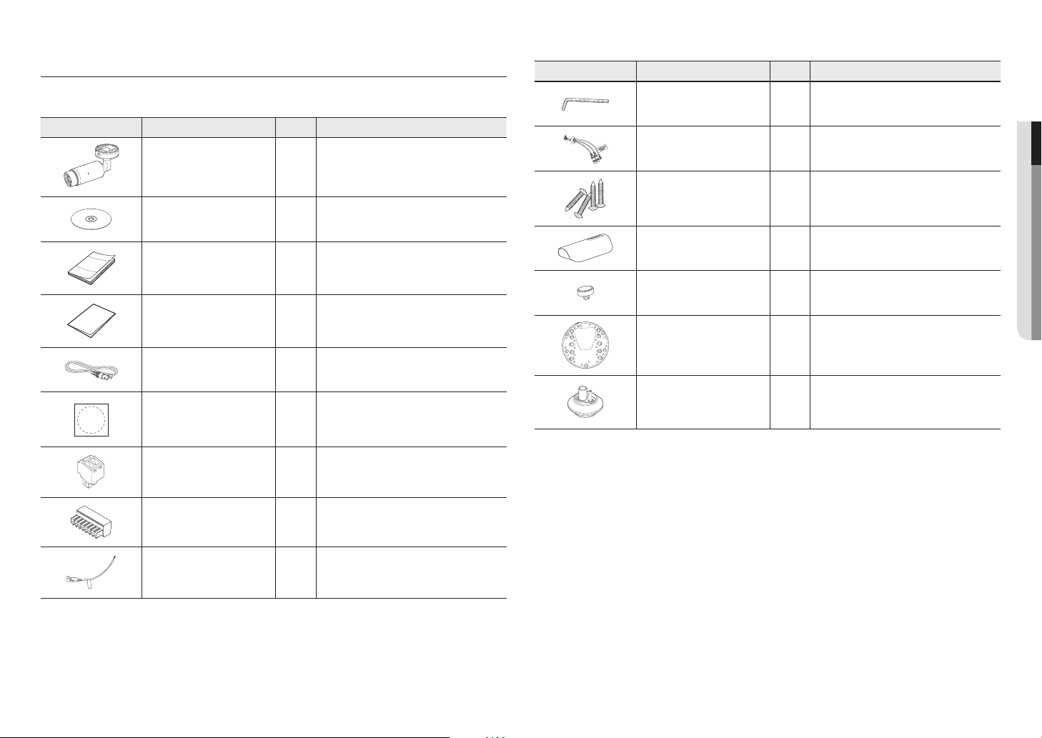
WHAT’S INCLUDED (TNO-4030T/4040T/4050T/4030TR/4040TR)
Please check if your camera and accessories are all included in the product package.
(As for each sales country, accessories are not the same.)
Appearance Item Name Quantity Description
Camera
1
Appearance Item Name Quantity Description
L Wrench
Audio/alarm cable
1
1
Used to control the direction of the camera
Used to connect with the audio and alarm port
●● OVERVIEW
Tapping Screw
Instruction book,
Installer S/W CD
1
Sunshield
Quick Guide
(Optional)
1
Sunshield Hold
Warranty card
(Optional)
1
CONDUIT
BASE WALL MOUNT
Cable for the testing monitor
Used to test the camera connection to a portable
1
display device
Cable bush
Template
Power Terminal Block
Audio/alarm Terminal Block
CAUTION: Be ware of the
Rated Voltage and Polarity
of the power connection.
Power Cable
1
1
1
1
Product installation guide
Plugged in the power plug
Plugged in the audio/alarm plug
Used to plug into the power port
4
1
1
1
1
Used for installation on the wall or ceiling
It protects the camera from the direct sunlight.
It fixes the sunshield with the camera.
The adapter that should be adjusted in order to hang
the camera on the wall
Used to connect the LAN cable with a diameter of
Ø7~8.5.
English _7
overview
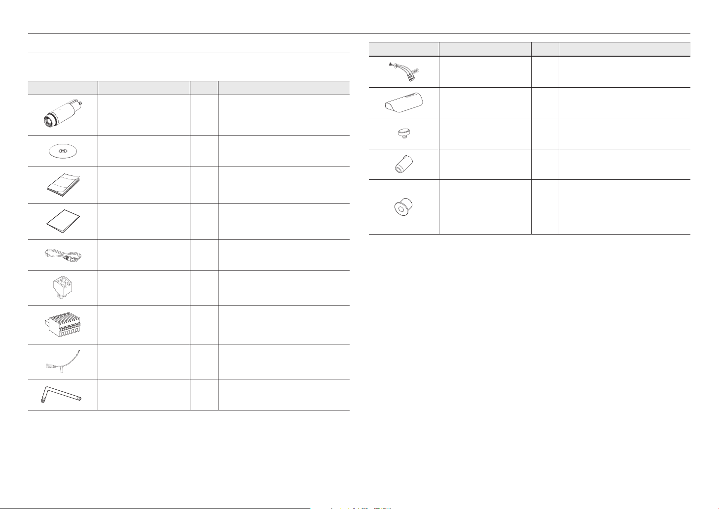
WHAT’S INCLUDED (TNO-4041T/4051T/4041TR)
Please check if your camera and accessories are all included in the product package.
(As for each sales country, accessories are not the same.)
Appearance Item Name Quantity Description
Camera
Instruction book,
Installer S/W CD
Quick Guide
(Optional)
Warranty card
(Optional)
Cable for the testing monitor
Power Terminal Block
Audio/alarm Terminal Block
1
1
1
1
Used to test the camera connection to a portable
1
1
1
Plugged in the power plug
Plugged in the audio/alarm plug
display device
Appearance Item Name Quantity Description
Audio/alarm cable
Sunshield
Sunshield Hold
Waterproof stopper
1
Used to connect with the audio and alarm port
1
It protects the camera from the direct sunlight.
1
1
It fixes the sunshield with the camera.
Used to block a hole from which the cable does not
come out
Cable range: Ø2mm(minimum) ~ Ø6mm(maximum)
Used for connecting cables (Ex: Power cable)
Waterproof adapter
1
※
Provided cable glands from the camera will be
applicable to Ø4.5mm(minimum) ~ Ø10mm(maximum)
cable
Rated Voltage and Polarity
of the power connection.
8_ overview
CAUTION: Be ware of the
Power Cable
Star-Shape wrench
1
1
Used to plug into the power port
Used to fasten the PT bracket to the main body

AT A GLANCE (TNO-4030T/4040T/4050T/4030TR/4040TR)
12345 67 8
1:LINE IN
2:GND
3:AUDIO OUT R
4:AUDIO OUT L
5:GND
6:ALARM IN
7:ALARM OU T
8:ALARM OUT 2
AT A GLANCE (TNO-4041T/4051T/4041TR)
Appearance & Components
Item Description
Network Port Used to connect the PoE or Ethernet cable for network connection.
a
Power Port Used to plug the power cable.
b
Audio and alarm cable port Port to connect audio and alarm cables.
c
Sunshield Hold It fixes the sunshield with the camera.
d
Sunshield It protects the camera from the direct sunlight.
e
Test Monitor Out
f
Reset Button
g
MICRO USB port
h
Micro SD card slot This is a slot in which you can insert a Micro SD card.
i
b ca
d e
f g
hi
Output port for test monitoring the video output. Use the test monitor cable to connect to a
mobile display and check the test video.
The button restores all camera settings to the factory default.
Press and hold for about 5 seconds to reboot the system.
If you reset the camera, the network settings will be adjusted so that DHCP can be
J
enabled. If there is no DHCP server in the network, you must run the IP Installer
program to change the basic network settings such as IP address, Subnet mask,
Gateway, etc., before you can connect to the network.
Port to connect the Wi-Fi dongle.
You can check the installation video through the applications installed in the smartphone.
Refer to “Connect to WiFi dongle” on page 15.
WiFi dongle and OTG adapter are sold separately.
`
Appearance & Components
ba c d
Item Description
Audio and alarm cable port Port to connect audio and alarm cables.
a
Test Monitor Out
b
Power Port Used to plug the power cable.
c
Network Port Used to connect the PoE or Ethernet cable for network connection.
d
Micro SD card slot This is a slot in which you can insert a Micro SD card.
e
Reset Button
f
Output port for test monitoring the video output. Use the test monitor cable to connect to a
mobile display and check the test video.
The button restores all camera settings to the factory default.
Press and hold for about 5 seconds to reboot the system.
If you reset the camera, the network settings will be adjusted so that DHCP can be
J
enabled. If there is no DHCP server in the network, you must run the IP Installer
program to change the basic network settings such as IP address, Subnet mask,
Gateway, etc., before you can connect to the network.
●● OVERVIEW
ef
English _9

installation & connection
installation & connection
INSTALLATION (TNO-4030T/4040T/4050T/4030TR/4040TR)
This camera is waterproof and in compliance with the IP66 spec, but the jack connected to the external cable is not. You are
`
J
recommended to install this product below the edge of eaves to prevent the cable from being externally exposed.
Precautions before installation
Ensure you read out the following instructions before installing the camera:
• It must be installed on the area (ceiling or wall) that can withstand 5 times the weight of the camera
including the installation bracket.
• Stuck-in or peeled-off cables can cause damage to the product or a fire.
• For safety purposes, keep anyone else away from the installation site.
And put aside personal belongings from the site, just in case.
• Do not use the sunshield hole for any purpose other than for connecting the sunshield.
• If you use excessive force when installing the product, the camera may be damaged and malfunction.
If you forcibly install the product using non-compliant tools, the product may be damaged.
Installation
1. Use the four tapping screws provided to secure the base wall
mount.
CONDUIT
6. Adjust the camera direction using the L wrench provided.
When you adjust the camera position using a bracket, please loosen the
`
J
bracket screw, adjust the camera, and tighten it. If you attempt to adjust it
forcibly while the screw is tight, it may result in a scratch or other problems.
Connecting waterproof power cable and LAN cable
1. Pick off the extruded part of the rubber cover on the bottom side of
the bottom cover as shown in the figure below.
Use an appropriate cable bush for the LAN cable to be connected.
`
J
- Basic camera : Use the cable with a diameter of Ø5~6.5.
- Components provided : Use the cable with a diameter of Ø7~8.5.
2. Insert the power cable into the small hole made by removing the
projected part of the rubber plug in step 1 above.
3. Connect the power cable with the power terminal block.
1:LINE IN
2:GND
3:AUDIO OUT R
4:AUDIO OUT L
5:GND
6:ALARM IN
7:ALARM OUT
8:ALARM OUT2
123456 78
2. Hang the safety cable up on a hook that looks like an arrow in the
Bottom cover.
3. Connect the appropriate cables with camera terminals.
4. After placing the bottom cover on the base wall mount, use the L
wrench provided to connect and secure the three screws.
5. After placing the camera on the bottom cover, use the L wrench
provided to connect the three screws on the top cover.
10_ installation & connection
CAUTION: Be ware of the
Rated Voltage and Polar ity
of the power conn ectio n.

4. Insert the LAN cable into the large hole made by removing the
projected part of the rubber plug in step 1 above.
5. Remove the sheath with a cable cutter, and align the cables.
6. Connect the LAN cable with a LAN connector, and insert it into the
LAN tool.
7. Connect the finished cable to the Ethernet port.
1:LINE IN
2:GND
3:AUDIO OUT R
4:AUDIO OUT L
5:GND
6:ALARM IN
7:ALARM OUT
8:ALARM OUT2
123456 78
Outdoor installation
When you install it outside of the building, please waterproof it with waterproof butyl rubber tape (can be
purchased in stores) so that water does not leak from the gap of the cable connected to the outside.
1. Connect to cables, such as I/O and audio.
2. Wrap the black cable jacket (Area A) and the cable connection
area with waterproof (butyl rubber) tape so that more than half of
the butyl rubber tape is overlapped.
If the cable jacket is not waterproofed properly, then it can directly cause
`
J
CAUTION: Be ware of the
Rated Voltage and Polar ity
of the power conn ectio n.
leakage. Make sure to protect the cable with a dense layer of taping.
Waterproof butyl tape is made of butyl rubber that can be stretched to
`
Camera
Camera
Camera
System
●● INSTALLATION & CONNECTION
System
AA
System
twice its normal length.
Connecting the alarm and audio cable
1. Remove the rubber cover on the bottom side of the bottom cover
as shown in the figure below.
2. Insert the alarm/audio cable through the hole created by removing
the rubber cap in No. 1, and connect the cable to the alarm
terminal.
3. Align the cable so that it should not be damaged or jammed
when installing the camera.
4. Put the rubber cap located on the alarm/audio cable in the hole.
INSTALLATION (TNO-4041T/4051T/4041TR)
This camera is waterproof and in compliance with the IP66 spec, but the jack connected to the external cable is not. You are
`
J
recommended to install this product below the edge of eaves to prevent the cable from being externally exposed.
Precautions before installation
Ensure you read out the following instructions before installing the camera:
• It must be installed on the area (ceiling or wall) that can withstand 5 times the weight of the camera
including the installation bracket.
• Stuck-in or peeled-off cables can cause damage to the product or a fire.
• For safety purposes, keep anyone else away from the installation site.
And put aside personal belongings from the site, just in case.
• Do not use the sunshield hole for any purpose other than for connecting the sunshield.
1:LINE IN
2:GND
3:AUDIO OUT R
4:AUDIO OUT L
5:GND
6:ALARM IN
7:ALARM OUT
8:ALARM OUT2
1234567 8
CAUTION: Be ware o f the
Rated Voltage and P olari ty
of the power conne ction .
• If you use excessive force when installing the product, the camera may be damaged and malfunction.
If you forcibly install the product using non-compliant tools, the product may be damaged.
English _11

installation & connection
Installation
1. Use the star-shaped wrench to separate the
PT bracket from the main body.
2. Tighten the PT driver and PT bracket by fixing screws into the three holes as
shown in the figure.
PT driver is not provided.
`
M
3. Use the star-shaped wrench to tighten the PT
bracket and main body.
When you adjust the camera position using a
`
J
bracket, please loosen the bracket screw, adjust
the camera, and tighten it. If you attempt to adjust
it forcibly while the screw is tight, it may result in
a scratch or other problems.
Connecting waterproof power cable and LAN cable
1. Pick off the extruded part of the rubber cover on
the bottom side of the bottom cover as shown in
the figure below.
Use an appropriate cable bush for the LAN cable to
`
J
be connected.
- Basic camera : Use the cable with a diameter of
Ø5~6.5.
- Components provided : Use the cable with a diameter of Ø7~8.5.
2. Insert the power cable into the center hole made by removing the projected part of the rubber plug in step
1 above.
3. Connect the power cable with the power terminal block.
4. Insert the LAN cable into the right hole made by removing the projected part of the rubber plug in step 1
above.
5. Remove the sheath with a cable cutter, and align the cables.
6. Connect the LAN cable with a LAN connector, and insert it into the LAN tool.
7. Connect the finished cable to the Ethernet port.
8. Insert the terminal block cable into the left hole made by removing the projected part of the rubber plug in
step 1 above.
left
center
right
Outdoor installation
When you install it outside of the building, please waterproof it with waterproof butyl rubber tape (can be
purchased in stores) so that water does not leak from the gap of the cable connected to the outside.
1. Connect to cables, such as I/O and audio.
2. Wrap the black cable jacket (Area A) and the cable connection
area with waterproof (butyl rubber) tape so that more than half of
the butyl rubber tape is overlapped.
If the cable jacket is not waterproofed properly, then it can directly cause
`
J
leakage. Make sure to protect the cable with a dense layer of taping.
Waterproof butyl tape is made of butyl rubber that can be stretched to
`
twice its normal length.
Camera
Camera
Camera
System
System
AA
System
12_ installation & connection

INSERTING/REMOVING A MICRO SD MEMORY CARD
Disconnect the power cable from the camera before inserting the Micro SD memory card.
`
J
Do not insert the Micro SD memory card while it’s upside down by force.
`
Otherwise, it may damage the Micro SD memory card.
When it rains or the humidity is high, insertion or ejection of a Micro SD card is not recommended.
`
Inserting a Micro SD Memory Card
Insert a Micro SD card in the arrow direction shown in the figure.
Removing a Micro SD Memory Card
Gently press down on the exposed end of the memory card as shown in the diagram to eject the memory
card from the slot.
●● INSTALLATION & CONNECTION
<
TNO-4030T/4040T/4050T/4030TR/4040TR
<
TNO-4041T/4051T/4041TR
>
<
TNO-4030T/4040T/4050T/4030TR/4040TR
>
<
TNO-4041T/4051T/4041TR
Pressing too hard on the Micro SD memory card can cause the card to shoot out uncontrollably from the slot when released.
`
J
Before removing the Micro SD memory card, in <Storage>, set the device to <Off> and press the [Apply] button and turn
`
the camera off.
If you turn off the camera or remove the Micro SD memory card that contains data from the product, the data may be lost or
`
damaged.
>
>
English _13
 Loading...