

Samsung TMC-FSCM1-B, TMC-FSCM1ACM-A, TMC-FSCM1POEM-A, TMC-FSCS1-B, TMC-FSCS1ACM-A User Manual
...Page 1
INSTALLATION AND OPERATION MANUAL TMC-F SERIES
TMC-F Series
10/100 MBPS ETHERNET 2 PORT MEDIA CONVERTER
This manual serves the
following Model Names:
TMC-FSTM1ACM-A
TMC-FSTS1ACM-A
TMC-FSTM1POEM-A
TMC-FSTS1POEM-A
TMC-FSTM1-B
TMC-FSTS1-B
TMC-FSCM1ACM-A
TMC-FSCS1ACM-A
TMC-FSCM1POEM-A
TMC-FSCS1POEM-A
TMC-FSCM1-B
TMC-FSCS1-B
TMC-FSFPPOE30M
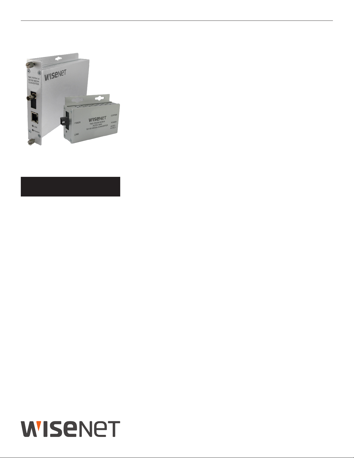
1 CHANNEL: ELECTRICAL
The TMC-F series converts 10/100 Mbps Fast Ethernet from an electrical signal to an
optical signal and back to an electrical signal. The electrical connection uses an RJ45
data connector.
Depending on the specific model in use, the optical connector is either a ST or SC, 1
or 2 Fibers, multimode (M) or singlemode (S), and the unit operates on either AC /
DC or DC only power.
The TMC-F Series standard size units may be directly plugged into the SBP-C14 or
SBP-C03 Racks or operated as a standalone module. The TMC-F-M small size units
operate as standalone modules only.
OPTICAL
1
INS_TMC-F_REV– 08/12/19 PAGE 1
Page 2
INSTALLATION AND OPERATION MANUAL TMC-F SERIES
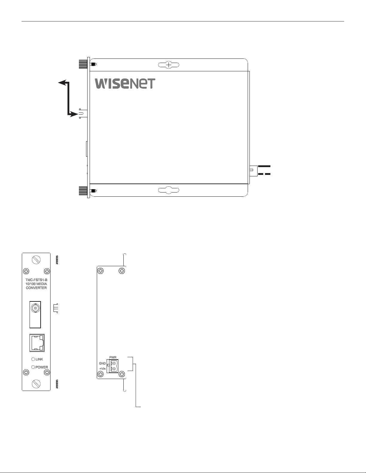
FIGURE 1 – TMC-F SERIES STANDARD SIZE UNIT
MULTIMODE OR
SINGLE MODE
OPTICAL FIBER
BLACK
BLACK WITH WHITE STRIPE
FIGURE 2 – TMC-F SERIES STANDARD SIZE UNIT
REAR PANELFRONT PANEL
NOTE: Remove Electrical Connector for Rack Mount Units
INS_TMC-F_REV– 08/12/19 PAGE 2
Page 3

INSTALLATION AND OPERATION MANUAL TMC-F SERIES
FIGURE 3 – TMC-F SERIES SMALL SIZE UNIT
MULTIMODE OR
SINGLE MODE
OPTICAL FIBER
BLACK
BLACK WITH WHITE STRIPE
FIGURE 4 – TMC-F SERIES SMALL SIZE UNIT
REAR PANELFRONT PANEL
INS_TMC-F_REV– 08/12/19 PAGE 3
Page 4

INSTALLATION AND OPERATION MANUAL TMC-F SERIES
FIGURE 5 – TMC-F SERIES SMALL SIZE UNIT WITH 30 W PoE
CAT5e/6
BLACK
BLACK
W/WHITE STRIPE
Surface Mount
Power Supply: 48VDC @ 1.25A
FIGURE 6 – TMC-F SERIES SMALL SIZE UNIT WITH 30 W PoE
REAR PANELFRONT PANEL
OPTICAL FIBER
DEPENDENT ON
MODEL NAME
INS_TMC-F_REV– 08/12/19 PAGE 4
Page 5

INSTALLATION AND OPERATION MANUAL TMC-F SERIES
FIGURE 7– POSSIBLE ETHERNET CONFIGURATION
Ethernet IEEE 802.3 Network Element determined by user.
Optical Fiber
ST
Connectors
CAT5e/6 with
RJ45 Connections
Ethernet IEEE 802.3
Network Element
A Unit B Unit
FIGURE 8 – LED INDICATORS
FX LINK/ACT POE POWER
GREEN
OFF
Fiber interface linked
(when lit or flashing)
Fiber interface not
linked.
FIGURE 9 – PoE PIN ASSIGNMENT
Power is being
supplied by unit
Power not supplied
by unit.
(No PoE device)
CAT5e/6 with
RJ45 Connections
Ethernet IEEE 802.3
Network Element
Unit powered up
Unit powered down
RJ-45 port supports IEEE802.3af/IEEE802.3at
End-point: Positive (VCC+): RJ45 pin 1, 2 or 4, 5
Negative (VCC-): RJ45 pin 3, 6 or 7,8
Data: (1, 2, 3, 6)
INS_TMC-F_REV– 08/12/19 PAGE 5
Page 6

INSTALLATION AND OPERATION MANUAL TMC-F SERIES
INSTALLATION CONSIDERATIONS
This fiber-optic link is supplied as a Standalone/Rack module. Units should
be installed in dry locations protected from extremes of temperature and
humidity.
SBP-C14 / SBP-C03 CARD CAGE RACKS
CAUTION: Although the units are hot-swappable and may be installed
without turning
power off to the rack, Hanwha recommends that the
power supply be turned off and that the rack power supply is
disconnected from any power source. Note: Remove electrical connector
before installing in card cage rack.
1.
Make sure that the card is oriented
card guides in the rack
until the edge connector at the back of the card
right side up, and slide it into the
seats in the corresponding slot in the rack’s connector panel. Seating
may require thumb pressure on the top and bottom of the card’s front
panel.
CAUTION: Take care not to press on any of the LEDs.
2. Tighten the two thumb screws on the card until the front panel of the
card is seated against the front of the rack.
WARNING: Unit is to be used with a Listed Class 2 power supply.
FIGURE A
Dimensions are for a small size module
FIGURE B
Dimensions are for a standard one slot module
IMPORTANT SAFEGUARDS:
A) Elevated Operating Ambient - If installed in a closed or multi-unit rack
assembly, the operating ambient temperature of the rack environment
may be greater than room ambient. Therefore, consideration should
be given to installing the equipment in an environment compatible
with the maximum ambient temperature (Tma) specified by the
manufacturer.
B) Reduced Air Flow - Installation of the equipment in a rack should be
such that the amount of air flow required for safe operation of the
equipment is not compromised.
.156 [3.96 mm]
.313 [7.95 mm]
INS_TMC-F_REV– 08/12/19 PAGE 6
 Loading...