

Samsung THxxxEAVx Installation Manual
ENGLISH
System Air Conditioner
(Cooling and Heating)
ESPAÑOLFRANÇAISITALIANOPORTUGUÊSDEUTSCHEΛΛHNIKARUSSIAN
DB98-24340A(5)SE F I DP G R
INSTALLATION
MANUAL
Cassette Type Series
TH
EAV
E-2
Safety Precautions
(Carefully follow the precautions listed below because they are essential to guarantee the safety of the equipment.)
WARNING
• Always disconnect the air conditioner from the power supply before servicing it or
accessing its internal components.
•
Verify that installation and testing operations are performed by qualified personnel.
• Verify that the air conditioner is not installed in an easily accessible area.
GENERAL INFORMATION
Carefully read the content of this manual before installing the air conditioner and store the manual in a safe place in order to be
able to use it as reference after installation.
For maximum safety, installers should always carefully read the following warnings.
Store the operation and installation manual in a safe location and remember to hand it over to the new owner if the
air conditioner is sold or transferred.
This manual explains how to install an indoor unit with a split system with two SAMSUNG units. The use of other types of units
with different control systems may damage the units and invalidate the warranty. The manufacturer shall not be responsible for
damages arising from the use of non compliant units.
The manufacturer shall not be responsible for damage originating from unauthorized changes or the improper connection of electric
and hydraulic lines. Failure to comply with these instructions or to comply with the requirements set forth in the “Operating limits”
table, included in the manual, shall immediately invalidate the warranty.
The air conditioner should be used only for the applications for which it has been designed: the indoor unit is not suitable to be
installed in areas used for laundry.
Do not use the units if damaged. If problems occur, switch the unit off and disconnect it from the power supply.
In order to prevent electric shocks, fires or injuries, always stop the unit, disable the protection switch and contact SAMSUNG’s
technical support if the unit produces smoke, if the power cable is hot or damaged or if the unit is very noisy.
Always remember to inspect the unit, electric connections, refrigerant tubes and protections regularly. These operations should be
performed by qualified personnel only.
The unit contains moving parts, which should always be kept out of the reach of children.
Do not attempt to repair, move, alter or reinstall the unit. If performed by unauthorized personnel, these operations may cause
electric shocks or fires.
Do not place containers with liquids or other objects on the unit.
All the materials used for the manufacture and packaging of the air conditioner are recyclable.
The packing material and exhaust batteries of the remote control(optional) must be disposed of in accordance with current laws.
The air conditioner contains a refrigerant that has to be disposed of as special waste. At the end of its life cycle, the air conditioner
must be disposed of in authorized centers or returned to the retailer so that it can be disposed of correctly and safely.
INSTALLING THE UNIT
IMPORTANT: When installing the unit, always remember to connect first the refrigerant tubes, then the electrical lines.
Always disassemble the electric lines before the refrigerant tubes.
Upon receipt, inspect the product to verify that it has not been damaged during transport. If the product appears damaged,
DO NOT INSTALL it and immediately report the damage to the carrier or retailer (if the installer or the authorized technician has
collected the material from the retailer.)
After completing the installation, always carry out a functional test and provide the instructions on how to operate
the air conditioner to the user.
Do not use the air conditioner in environments with hazardous substances or close to equipment that release free flames to avoid
the occurrence of fires, explosions or injuries.
POWER SUPPLY LINE, FUSE OR CIRCUIT BREAKER
Always make sure that the power supply is compliant with current safety standards. Always install the air conditioner in compliance
with current local safety standards.
Always verify that a suitable grounding connection is available.
Verify that the voltage and frequency of the power supply comply with the specifications and that the installed power is sufficient
to ensure the operation of any other domestic appliance connected to the same electric lines.
Always verify that the cut-off and protection switches are suitably dimensioned.
Verify that the air conditioner is connected to the power supply in accordance with the instructions provided in the wiring
diagram included in the manual.
Always verify that electric connections (cable entry, section of leads, protections…) are compliant with the electric specifications
and with the instructions provided in the wiring scheme. Always verify that all connections comply with the standards applicable
to the installation of air conditioners.

E-3
ENGLISH
Contents
Preparation for Installation. . . . . . . . . . . . . . . . . . . . . . . . . . . . . . . . . . . . . . . . . . 4
Deciding on Where to Install the Indoor Unit . . . . . . . . . . . . . . . . . . . . . . . 5
Indoor Unit Installation . . . . . . . . . . . . . . . . . . . . . . . . . . . . . . . . . . . . . . . . . . . . . 7
Purging the Unit . . . . . . . . . . . . . . . . . . . . . . . . . . . . . . . . . . . . . . . . . . . . . . . . . . . . 8
Connecting the Refrigerant Pipe . . . . . . . . . . . . . . . . . . . . . . . . . . . . . . . . . . . 9
Cutting/Flaring the Pipes . . . . . . . . . . . . . . . . . . . . . . . . . . . . . . . . . . . . . . . . . . 10
Performing Leak Test & Insulation . . . . . . . . . . . . . . . . . . . . . . . . . . . . . . . . . 11
Drainpipe and Drain Hose Installation . . . . . . . . . . . . . . . . . . . . . . . . . . . . . 12
Connecting the Connection Cord . . . . . . . . . . . . . . . . . . . . . . . . . . . . . . . . . 14
Assigning Address to Indoor Unit . . . . . . . . . . . . . . . . . . . . . . . . . . . . . . . . . 15
Installing the Safety Net & Air blocking kits . . . . . . . . . . . . . . . . . . . . . . . . 17
Technical Specification & Product feature . . . . . . . . . . . . . . . . . . . . . . . . . 17
Troubleshooting . . . . . . . . . . . . . . . . . . . . . . . . . . . . . . . . . . . . . . . . . . . . . . . . . . . 18
Additional Accessories . . . . . . . . . . . . . . . . . . . . . . . . . . . . . . . . . . . . . . . . . . . . . 22

E-4
Preparation for Installation
When deciding on the location of the air conditioner with the owner,
the following restrictions must be taken into account.
General
Do NOT install the air conditioner in a location where it will come into contact
with the following elements:
Combustible gases
Saline air
Machine oil
Sulphide gas
Special environmental conditions
If you must install the unit in such conditions, first consult your dealer.
Avoid installing the air conditioner:
In areas where it is exposed to direct sunlight. Close to heat sources.
In damp areas or locations where it could come into contact with water.
(for example rooms used for laundry)
In areas where curtains and furniture could affect the supply and discharge of air.
Without leaving the required minimum space around the unit. (as shown in the
drawing)
In scarcely ventilated areas.
On surfaces that are unable to support the weight of the unit without deforming,
breaking or causing vibrations during the use of the air conditioner.
In a position that does not enable the condensate drainage pipe to be correctly
installed. (at the end of the installation. It is always essential to check the efficiency
of the drainage system)
Accessories
The following accessories are supplied with the indoor unit.
The type and quantity may differ depending on the specifications.
Pattern sheet Insulation drain hose Insulation pipe Insulation cover band Cable-tie
Flexible hose M4x12
tapped screw
Pad stopper
User's manual
Installation
manual
Safety net M4x12
tapped screw
E-5
Deciding on Where to Install the Indoor Unit
Indoor Unit
There must be no obstacles near the air inlet and outlet.
Install the indoor unit on a ceiling that can support its weight.
Maintain sufficient clearance around the indoor unit.
Make sure that the water dripping from the drain hose runs away correctly and
safely.
The indoor unit must be installed in this way, that they are out of public access.
(Not touchable by the users)
ENGLISH
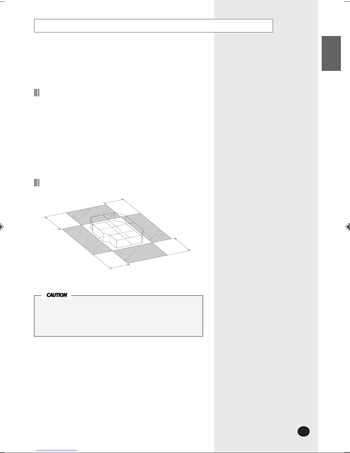
Space Requirements for Indoor Unit
The units must be installed according to distances declared,
in order to permit accessibility from each side, either to guarantee
correct operation of maintenance or repairing products.
The unit’s parts must be reachable and removable completely
under safety condition (for people or things).
CAUTION
1500 mm or more
1500 mm or more
1500 mm or more
1500 mm or more
E-6
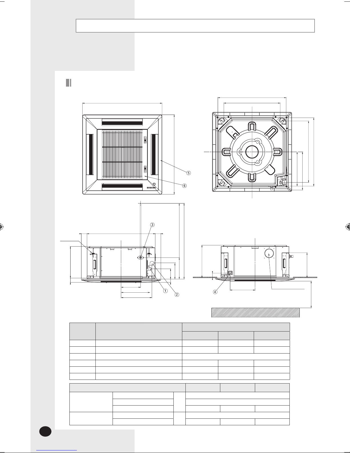
Drawing of the indoor unit
No. Name
Description
026/035
052
060
1
Liquid pipe connection
ø
6.35
ø
6.35
ø
6.35
2
Gas pipe connection
ø
9.52
ø
12.70
ø
15.88
3
Drain pipe connection
OD: 29/ ID: 25
4
Power supply connection
- - -
5
Air discharge grille
- - -
6
Air suction grille
- - -
Deciding on Where to Install the Indoor Unit (continued)
Dimension and weight
026/035
052
060
Net dimension
Indoor unit
mm
575X260X575
Panel size
670X35X670
Outdoor unit
790X548X285 880X638X310 880X798X310
Net weight
Indoor unit+Panel
kg
19.6
Outdoor unit
32.6 50 57
Unit : mm
577~610 (Ceiling opening)
577~610 (Ceiling opening)
476 (Suspension position)
518 (Suspension position)
Required space
Fresh air intake hole
Suspension
bolt
4-M8~M10
670
670
288
321
Adjustable (0~570)
750
180
133
86
28
26736
1000 or more
275
212
39
575 4848
210
164
244
260
E-7
20mm
Indoor Unit
Ceiling
Gauge of
Dimensions
17mm
ENGLISH
Indoor Unit Installation
It is recommended to install the refnet joint before installing the indoor unit.
1
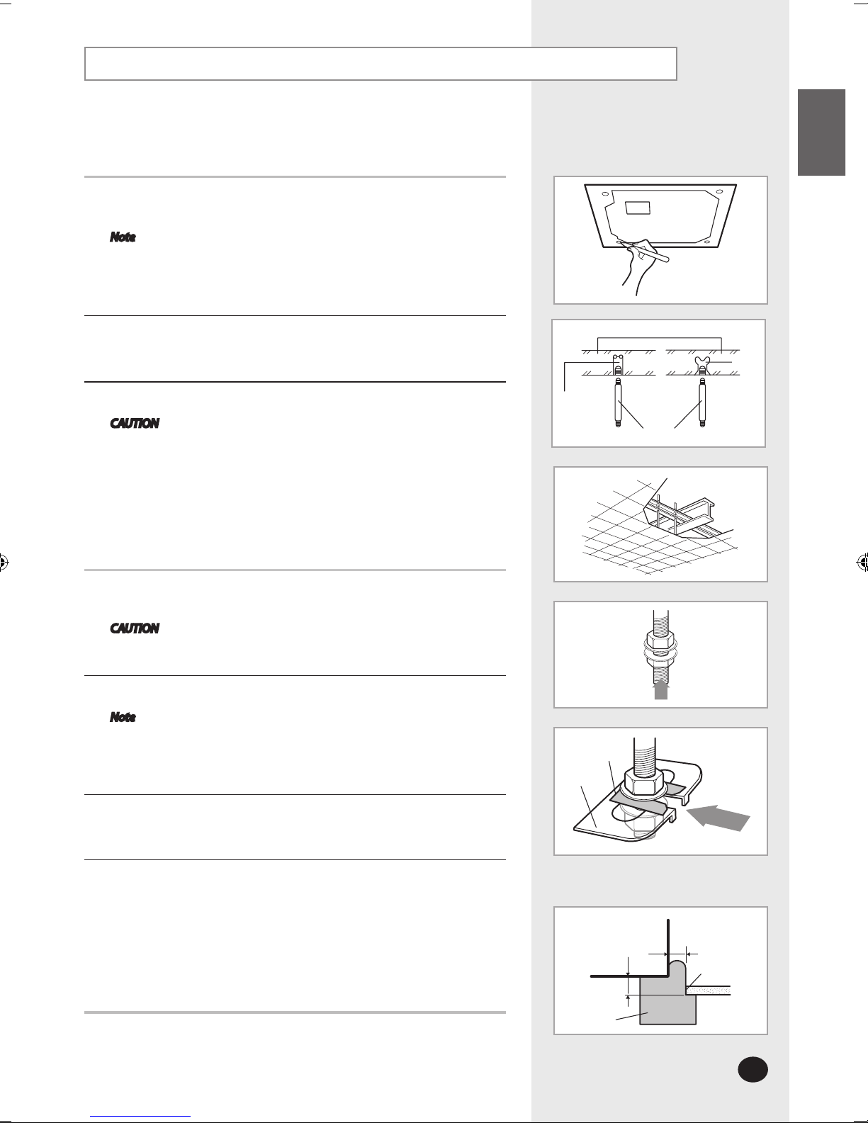
Place the pattern sheet on the ceiling at the spot where you want to install
the indoor unit.
Note
Since the diagram is made of paper, it may shrink or stretch
slightly due to temperature or humidity. For this reason, before
drilling the holes maintain the correct dimensions between the
markings; refer to page 6.
2
Insert bolt anchors, use existing ceiling supports or construct a suitable
support as shown in figure.
3
Install the suspension bolts depending on the ceiling type.
CAUTION Ensure that the ceiling is strong enough to support the
weight of the indoor unit. Before hanging the unit, test
the strength of each attached suspension bolt.
If the length of suspension bolt is more than 1.5m,
it is required to prevent vibration.
If this is not possible, create an opening on the false
ceiling in order to be able to use it to perform the
required operations on the indoor unit.
4
Screw eight nuts to the suspension bolts making space for hanging the
indoor unit.
CAUTION You must install the suspension bolts more than four when
installing the indoor unit.
5
Hang the indoor unit to the suspension bolts between two nuts.
Note Piping must be laid and connected inside the ceiling when
suspending the unit. If the ceiling is already constructed,
lay the piping into position for connection to the unit before
placing the unit inside the ceiling.
6
Screw the nuts to suspend the unit. Cut a pad stopper and place it on the
bracket at this time.
7
Adjust the unit to the appropriate position considering the installation area for the
front panel.
7-1 Place the pattern sheet on the indoor unit.
7-2 Adjust a space between the ceiling and the indoor unit by using the gauge
of dimensions.
7-3 Fix the indoor unit securely after adjusting level of the unit by using a leveler.
7-4 Remove the pattern sheet, connect the other cables and install the front panel.
Concrete
Suspension bolt(M8)-field supply
Hole in anchor
Hole in plug
Insert
Ceiling support
Pad stopper
Bracket
E-8
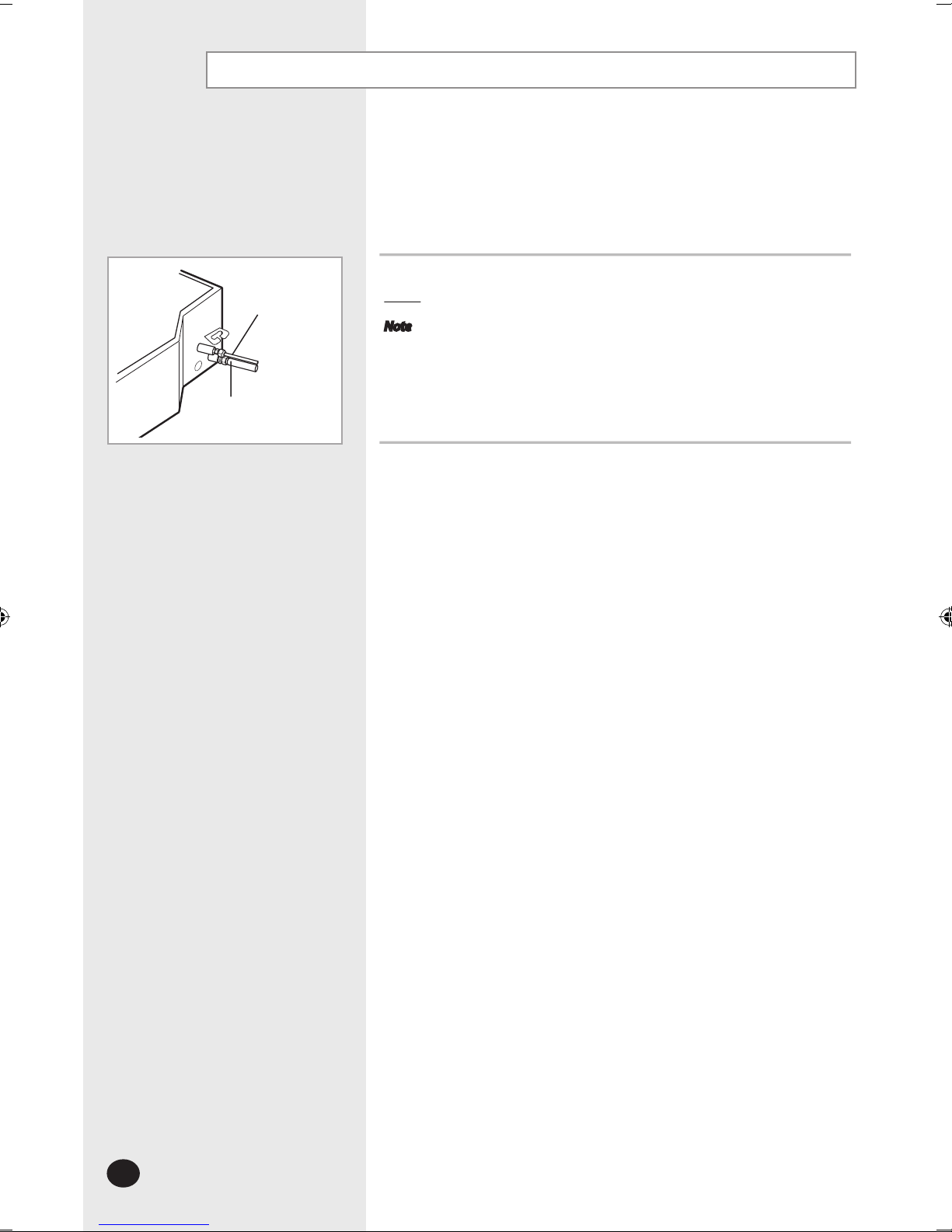
Purging the Unit
Liquid refrigerant
port
Gas refrigerant port
From factory the unit is supplied and set with a pre-charge of nitrogen gas
(insert gas). Therefore, all insert gas must be purged before connecting the
assembly piping.
Unscrew the pinch pipe at the end of each refrigerant pipe.
Result:
All inert gas escapes from the indoor unit.
Note
To prevent dirt or foreign objects from getting into the pipes during
installation, do NOT remove the pinch pipe completely until you are ready to
connect the piping.
 Loading...