

Samsung KX20, TX22, TX25, THX22, THX25 Schematic
...
DVD RECEIVER AMP
BASIC MODEL: HT-X20
SERVICE
Manual
DVD RECEIVER AMP SYSTEM Features
* Multi-Disc Playback & FM Tuner
* Dolby Pro Logic II
* DTS (Digital Theater Systems)
* TV Screen Saver Function
* Customized TV Screen Display
- Confidential -
MODEL : HT-X20
* Application : HT-X20/ KX20/ TX22/ TX25
HT-THX22/ THX25
HT-TKX22/ TKX25
© Samsung Electronics Co.,Ltd.MAR. 2005
Printed in Korea
Code no.AH68-01771Y
ELECTRONICS

Ch1 Precautions
1-1. Safety Precautions 1-1
1-2. Servicing Precautions 1-2
1-3. Precautions for Electrostatically
Sensitive Device (ESDs) 1-3
1-4. Special Precautions and Warning
Lables for Laser Products 1-4
1-5. Special Precautions for HDD 1-5
INDEX
Ch2 Product Descriptions
1. Product Feature 2-1
2. Specifications 2-2
3. Notes on Discs 2-3
4. Accessories 2-4
Ch3 Product Functions
1. SPK Connection & Setup 3-1
2. Main Functions 3-2
3. New Functions 3-3
Ch4 Adjustments
Protection Mode Explanation 4-1
Ch5 How to disassemble
How to disassemble 5-1
Ch6 Troubleshooting
1. No Power 6-1
2. No Output 6-2
3. DVD MPEG 6-4
4. DVD SERVO 6-6
Ch7 Exploded View & Parts List
1. Total Exploded View 7-1
2. Parts List 7-5
Ch8 Electrical Parts List
Electrical Parts List 8-1
Ch9 Block Diagram
MAIN 9-1
DVD 9-2
Ch10 Wiring Diagram
Wiring Diagram 10-1
Ch11 PCB Diagram
1. MAIN 11-1
2. AMP 11-2
Ch12 Schematic Diagram
1. AMP 12-1
2. MAIN 12-2
3. FRONT 12-3
4. AUX 12-4
5. MPEG 12-5
6. KARAOKE 12-6
Ch13 Circuit Description
Circuit Board Description 13-1
Ch14 HTS Reference
1. HTS (Home Theater Sytsem) 14-1
2. About “Sound” 14-2
3. 5.1 Channel Sound 14-3
4. HTS Sound Format 14-4
5. HTS Devices 14-5
1. Precautions
Follow these safety, servicing and ESD precautions to prevent damage and protect against potential hazards
such as electrical shock and X-rays.
Samsung Electronics 1-1
1-1 Safety Precautions
1. Be sure that all of the built-in protective
devices are replaced.
2. When reinstalling the chassis and its
assemblies, be sure to restore all protective
devices, including control knobs and
compartment covers.
3. Make sure that there are no cabinet
openings through which people-particularly children--might insert fingers
and contact dangerous voltages. Such
openings include the spacing between the
picture tube and the cabinet mask,
excessively wide cabinet ventilation slots,
and improperly fitted back covers.
4. Design Alteration Warning:
Never alter or add to the mechanical or
electrical design of the unit. Example: Do
not add auxiliary audio or video connectors. Such alterations might create a safety
hazard. Also, any design changes or additions will void the manufacturer's warranty.
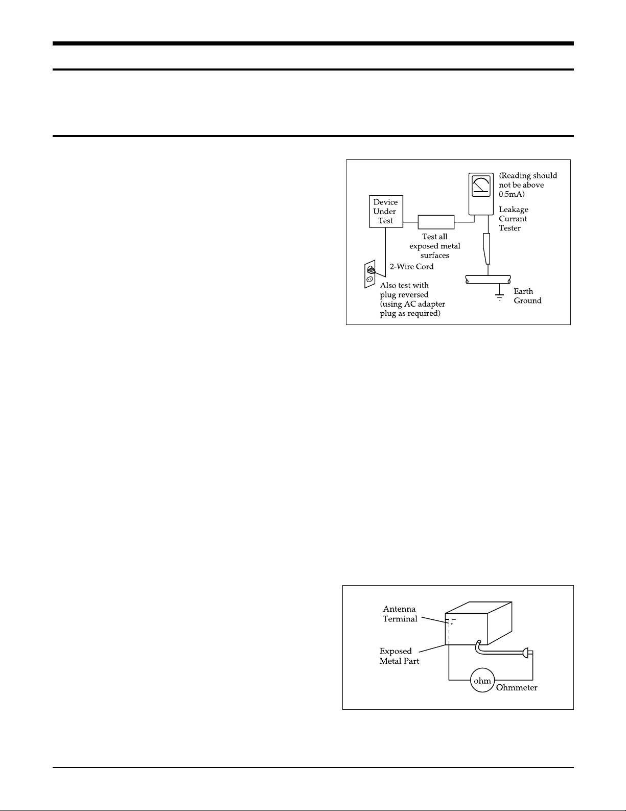
5. Leakage Current Hot Check (Figure 1-1):
Warning: Do not use an isolation
transformer during this test. Use a leakagecurrent tester or a metering system that
complies with American National Standards
Institute (ANSI C101.1, Leakage Current for
Appliances), and Underwriters Laboratories
(UL Publication UL1410, 59.7).
With the unit completely reassembled, plug
the AC line cord directly into a 120V AC
outlet. With the unit's AC switch first in
the ON position and then OFF, measure the
current between a known earth ground
(metal water pipe, etc.) and all exposed
metal parts. Examples: Handle brackets,
metal cabinets, screwheads and control
shafts. The current measured should not
exceed 0.5 milliamp. Reverse the powerplug prongs in the AC outlet and repeat.
6. Insulation Resistance Cold Check:
(1) With the unit's AC plug disconnected
from the AC source, connect an electrical
jumper across the two AC prongs. (2) Set
the power switch to ON. (3) Measure the
resistance between the shorted AC plug and
any exposed metallic parts. Example:
Screwheads, antenna, control shafts or
handle brackets.
If any of the exposed metallic parts has a
return path to the chassis, the measured
resistance should be between 1 and 5.2
megohms. If there is no return path, the
measured resistance should be "infinite." If
the resistance is outside these limits, a shock
hazard might exist. See Figure 1-2
Fig. 1-1 AC Leakage Test
Fig. 1-2 Insulation Resistance Test

Samsung Electronics1-2
1-1 Safety Precautions (Continued)
7. Components, parts and wiring that appear
to have overheated or that are otherwise
damaged should be replaced with parts
that meet the original specifications.
Always determine the cause of damage or
overheating, and correct any potential
hazards
8. Observe the original lead dress, especially
near the following areas: Antenna
wiring, sharp edges, and especially the
AC and high voltage power supplies.
Always inspect for pinched, out-of-place,
or frayed wiring. Do not change the
spacing between components and the
printed circuit board. Check the AC
power cord for damage. Make sure that
no wires or components touch thermally
hot parts.
9. Product Safety Notice:
Some electrical and mechanical parts
have special safety-related characteristics
which might not be obvious from visual
inspection. These safety features and the
protection they give might be lost if the
replacement component differs from the
original--even if the replacement is rated
for higher voltage, wattage, etc.
10 Components that are critical for safety are
indicated in the circuit diagram by
shading, or . Use replacement
components that have the same ratings,
especially for flame resistance and
dielectric strength specifications. A
replacement part that does not have the
same safety characteristics as the original
might create shock, fire or other hazards.
1-2 Servicing Precautions
1. Servicing precautions are printed on the
cabinet. Follow them.
2. Always unplug the unit's AC power cord
from the AC power source before
attempting to: (a) Remove or reinstall any
component or assembly, (b) Disconnect an
electrical plug or connector, (c) Connect a
test component in parallel with an
electrolytic capacitor.
3. Some components are raised above the
printed circuit board for safety. An
insulation tube or tape is sometimes used.
The internal wiring may be clamped to
prevent contact with thermally hot
components. Reinstall all such elements to
their original position.
4. After servicing, always check that the
screws, components and wiring have been
correctly reinstalled. Make sure that the
portion around the serviced part has not
been damaged.
5. Check the insulation between the blades of
the AC plug and accessible conductive parts
(examples: metal panels, input terminals
and earphone jacks).
6. Insulation Checking Procedure: Disconnect
the power cord from the AC source and
turn the power switch ON. Connect an
insulation resistance meter (500V) to the
blades of the AC plug.
The insulation resistance between each
blade of the AC plug and accessible
conductive parts (see above) should be
greater than 1 megohm.
7. Never defeat any of the B+ voltage
interlocks. Do not apply AC power to the
unit (or any of its assemblies) unless all
solid-state heat sinks are correctly installed.
8. Always connect a test instrument's ground
lead to the instrument chassis ground
before connecting the positive lead; always
remove the instrument's ground lead last.
Precautions
Warning1: First read the "Safety Precautions" section of this manual. If some unforeseen circumstance creates a conflict
between the servicing and safety precautions, always follow the safety precautions.
Samsung Electronics 1-3
1-3 Precautions for Electrostatically Sensitive Devices (ESDs)
1-4 Special Precautions and Warning Labels for Laser Products
1. Some semiconductor ("solid state") devices
are easily damaged by static electricity.
Such components are called Electrostatically
Sensitive Devices (ESDs). Examples include
integrated circuits and some field-effect
transistors. The following techniques will
reduce the occurrence of component
damage caused by static electricity.
2. Immediately before handling any
semiconductor components or assemblies,
drain the electrostatic charge from your
body by touching a known earth ground.
Alternatively, wear a discharging
wrist-strap device. (Be sure to remove it
prior to applying power--this is an electric
shock precaution.)
3. After removing an ESD-equipped assembly,
place it on a conductive surface such as
aluminum foil to prevent accumulation of
electrostatic charge.
4. Do not use freon-propelled chemicals.
These can generate electrical charges that
damage ESDs.
5. Use only a grounded-tip soldering iron
when soldering or unsoldering ESDs.
6. Use only an anti-static solder removal
device. Many solder removal devices are
not rated as "anti-static" (these can
accumulate sufficient electrical charge to
damage ESDs).
7. Do not remove a replacement ESD from its
protective package until you are ready to
install it. Most replacement ESDs are
packaged with leads that are electrically
shorted together by conductive foam,
aluminum foil or other conductive
materials.
8. Immediately before removing the protective
material from the leads of a replacement
ESD, touch the protective material to the
chassis or circuit assembly into which the
device will be installed.
9. Minimize body motions when handing
unpackaged replacement ESDs. Motions
such as brushing clothes together, or lifting
a foot from a carpeted floor can generate
enough static electricity to damage an ESD.
Precautions
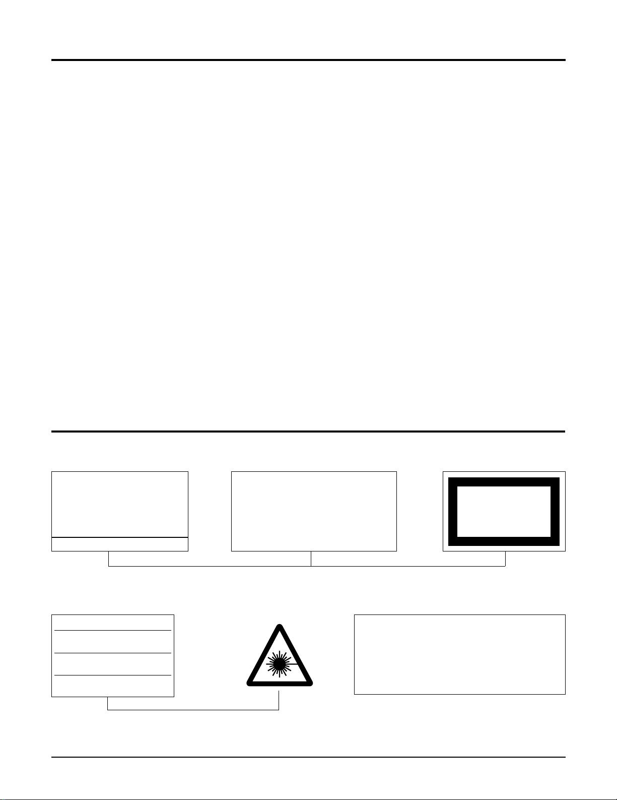
UL : Manufactured for U.S.A. Market.
CSA : Manufactured for Canadian Market.
EU : Manufactured for European Market.
SCAN : Manufactured for Scandinavian
Market.
This Product Complies with
DHHS Rules 21CFR, Sub
chapter J.At date of Manufacture
(UL)
(UL,CSA,SCAN)
(EU)
CERTIFIED ONLY TO CANADIAN
ELECTRICAL CODE.
CERTIFIE EN VERTU DU CODE
CANADIAN DE LELETRICITE
SEULEMENT
(CSA)
CLASS 1
LASER PRODUCT
(UL,CSA,EU)
Fig. 1-3 Warning Labels (Location: Enclosure Block)
Fig. 1-4 Warning Labels (Location: Disc Clamper, Inner Side of Unit Door or Nearby Unit Chassis )
CAUTION :
INVISIBLE LASER RADIATION WHEN OPEN
AND INTERLOCKS DEFEATEO AVOIDEXPOSURE TO BEAM
ADVARSEL:USYNLIG LASERSTRÅLING VED ABNING
NÅR SIKKERHEDSAFBRYDERE ER UDE AF FUNKTION
UNDGA UDSAETTELSE FOR STRALING
VARO:AVATTAESSA JA SUOJALUKITUS OHITETTAESSA
OLET ALTTINA NAKYMATTÖMALLE LASERSATEILYLLE ALA
KATSO SATEESEEN!
VARNING:
OSYNLIG LASERSTRÅLNING NAR DENNA DEL
AR OPPNAD OCH SPARREN AR URKOPPLAD BETRAKTA
EJSTRÅLEN!
Samsung Electronics1-4
1-4 Special Precautions and Warning Labels for Laser Products (Continued)
1-4-1 Warnings
1. When servicing, do not approach the LASER
exit with the eye too closely. In case it is
necessary to confirm LASER beam emission,
be sure to observe from a distance of more
than 30 cm from the surface of the objective
lens on the optical pick-up block.
2. Do not attempt to handle the objective lens
when the DISC is not on the tray.
1-4-2 Laser Diode Specifications
Material: GaAs+ GaAlAs
Wavelength: 760-800 nm
Emission Duration: Continuous
Laser Output: 0.2 mw (measured at a
1.6 mm distance from the objective lens
surface on the optical pick-up block.)
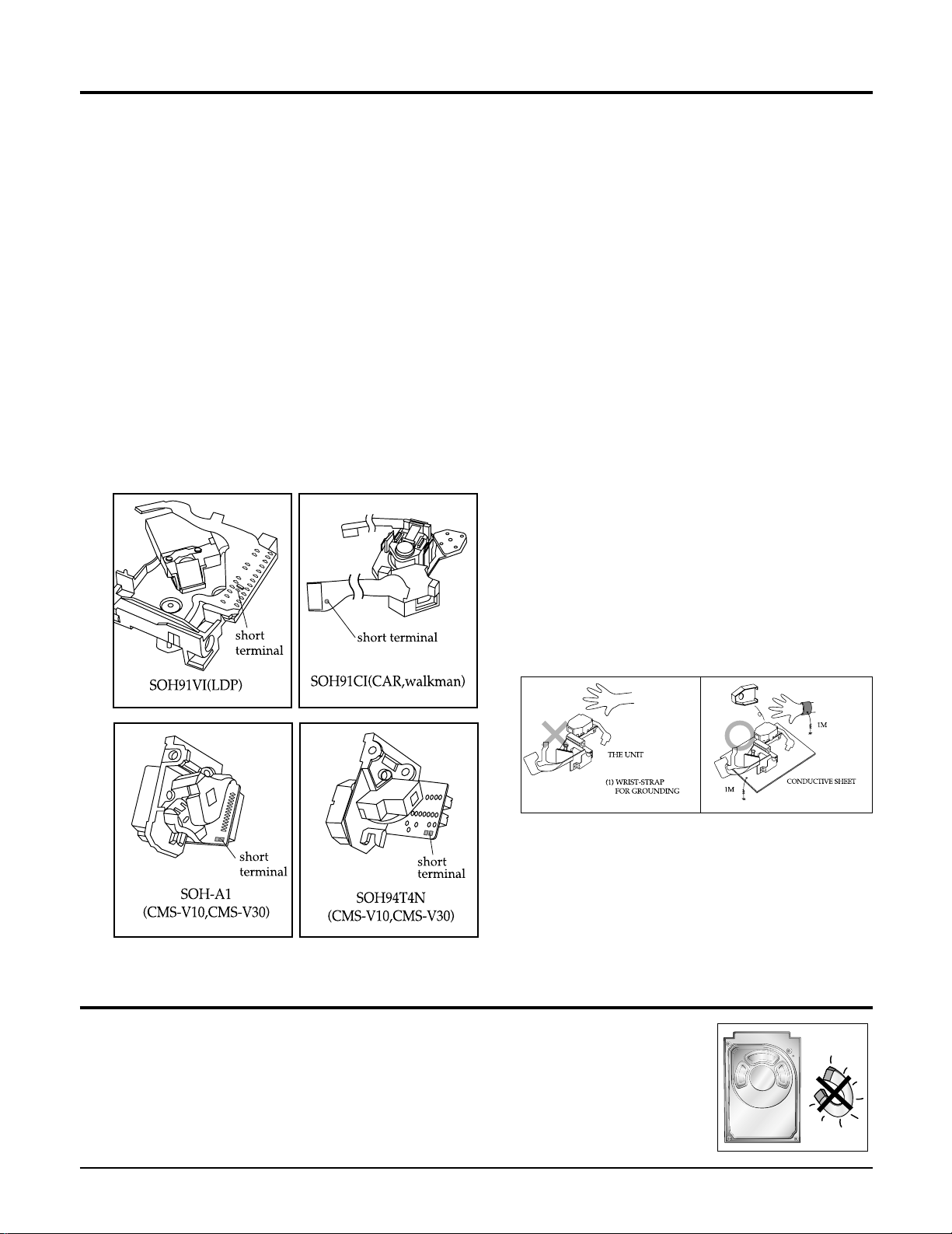
1-4-3 Handling the Optical Pick-up
1. Static electricity from clothing or the body
may cause electrostatic breakdown of the
laser diode in the Optical Pickup. Follow
this procedure:
2. Place a conductive sheet on the work bench
(i.e., the black sheet used for wrapping
repair parts.) Note: The surface of the work
bench should be covered by a copper
ground plane, which is grounded.
3. The repair technician must wear a wrist
strap which is grounded to the copper sheet.
4. To remove the Optical Pickup block:
Place the set on the conductive sheet, and
momentarily touch the conductive sheet
with both hands. (While working, do not
allow any electrostatic sources--such as
clothes--to touch the unit.)
5. Ground the "Short Terminal" (located on the
PCB, inside the Pickup Assembly) before
replacing the Pickup. This terminal should
be shorted whenever the Pickup Assembly
is lifted or moved.
6. After replacing the Pickup, reopen the Short
Terminal. See diagrams below:
Precautions
1-5 Special Precautions for HDD
* HDD Data Maintenance Step
1. Since the data on the HDD is weak to mechanical shock, place the HDD in a safe
location that is free from mechanical shock once it is removed from the main unit.
2. In order to safe keep the data on the HDD, back up the data before the repair or
make sure not to place the HDD near any electrical appliance that generates a strong
magnetic field.
Samsung Electronics 2-1
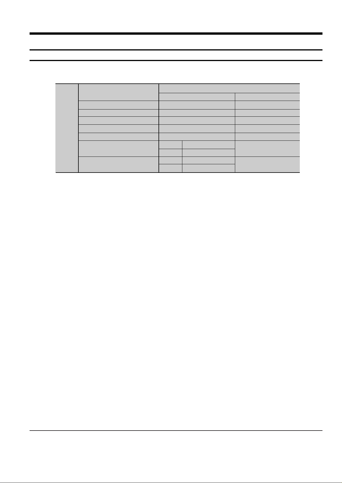
2. Product Description
1. Specifications
HT-X20
Speaker system
Impedance
Frequency range
Output sound pressure level
Rated input
Maximum input
Dimensions (W x H x D)
Weights
S
P
E
A
K
E
R
Subwoofer speaker
3Ω
35Hz~160Hz
85dB/W/M
100W
200W
175 x 320 x 381 mm
5.1 kg
Front/Rear
Center
90 x 152x 90 mm
200 x 90 x 92 mm
0.5 Kg/0.4 Kg
0.6 Kg
Front/Rear
Center
Front/Center/Rear speaker
3Ω x 5
140Hz~20KHz
82dB/W/M
80W
160W
5.1ch speaker system
2-2 Samsung Electronics
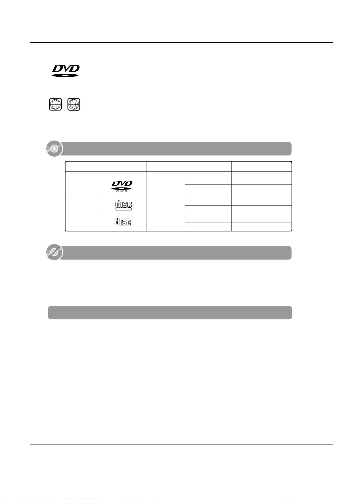
2. Notes on discs
DVD (Digital Versatile Disc) offers fantastic audio and video, thanks to Dolby Digital sur-
round sound and MPEG-2 video compression technology. Now you can enjoy these realistic
effects in the home, as if you were in a movie theater or concert hall.
V I D E O
DVD players and the discs are coded by region. These regional codes must match in order
for the disc to play. If the codes do not match, the disc will not play.
The Region Number for this player is given on the rear panel of the player.
(Your DVD player will only play DVDs that are labeled with identical region codes.)
1 6
~
•
LD, CD-G, CD-I, CD-ROM and DVD-ROM cannot be played on this player.
If such discs are played, a "WRONG DISC FORMAT" message appears on the TV screen.
•
DVD discs purchased abroad may not play on this player.
If such discs are played, a "WRONG REGION CODE" message appears on the TV screen.
Do not use the following types of disc!
•
Many DVD discs are encoded with copy protection. Because of this, you should only connect
your DVD player directly to your TV, not to a VCR. Connecting to a VCR results in a distorted picture from copy-protected DVD discs.
•
This product incorporates copyright protection technology that is protected by methods claims of certain
U.S. patents and other intellectual property rights owned by Macrovision Corporation and other rights
owners. Use of this copyright protection technology must be authorized by Macrovision Corporation, and
is intended for home and other limited viewing uses only unless otherwise authorized by Macrovision
Corporation. Reverse engineering or disassembly is prohibited.
Copy Protection
COMPACT
DIGITAL VIDEO
COMPACT
DIGITAL AUDIO
Mark (Logo)
Audio + Video
DVD
VIDEO-CD
AUDIO-CD
12cm
Approx. 240 min. (single-sided)
Approx. 480 min. (double-sided)
Approx. 80 min. (single-sided)
Approx. 160 min. (double-sided)
74 min.
20 min.
74 min.
20 min.
8cm
12cm
8cm
12cm
8cm
Audio + Video
Audio
Recorded Signals
Disc Type Disc Size Max. Playing Time
Playable Discs

Samsung Electronics 2-3
CD-R Discs
•
Some CD-R discs may not be playable depending on the disc recording device (CD-Recorder or PC) and the
condition of the disc.
•
Use a 650MB/74 minute CD-R disc.
Do not use CD-R disk over 700MB/80 minute as much as possible since it may not be played back.
•
Some CD-RW (Rewritable) media, may not be playable.
•
Only CD-Rs that are properly "closed" can be fully played. If the session is closed but the disc is left open, you
may not be able to fully play the disc.
CD-R JPEG Discs
•
Only files with the ".jpeg" and ".JPEG" extensions can be played.
•
If the disc is not closed, it will take longer to start playing and not all of the recorded files may be played.
•
Only CD-R discs with JPEG files in ISO 9660 or Joliet format can be played.
•
JPEG file names should be 8 characters or less in length and contain no blank spaces or special characters (. / = +).
•
Only a consecutively written multisession disc can be played. If there is a blank segment in the multisession disc, the
disc can be played only up to the blank segment.
•
A maximum of 9,999 images can be stored on a single CD.
•
When playing a Kodak/Fuji Picture CD, only the JPEG files in the picture folder can be played.
•
Picture discs other than Kodak/Fuji Picture CDs may take longer to start playing or may not play at all.
Disc Recording Format
CD-R MP3 Discs
•
Only CD-R discs with MP3 files in ISO 9660 or Joliet format can be played.
•
MP3 file names should be 8 characters or less in length and contain no blank spaces or special characters (. / = +).
•
Use discs recorded with a compression/decompression data rate greater than 128Kbps.
•
Only files with the ".mp3" and ".MP3" extensions can be played.
•
Only a consecutively written Multisession disc can be played. If there is a blank segment in the Multisession disc,
the disc can be played only up to the blank segment.
•
If the disc is not closed, it will take longer to begin playback and not all of the recorded files may be played.
•
For files encoded in Variable Bit Rate (VBR) format, i.e. files encoded in both low bit rate and high bit rate
(e.g., 32Kbps ~ 320Kbps), the sound may skip during playback.
•
A maximum of 500 tracks can be played per CD.
•
A maximum of 300 folders can be played per CD.

2-4 Samsung Electronics
3. Accessories
AH39-40001V CABLE-AUDIO CABLE;1P-1P,3000MM,- COMMON
AH42-00021A ANT FM T;T18011F-1,75 ohm,1800mm COMMON
AH59-01787S REMOCON-ASSY;HT-X20,XAA,AR-7060, US
Code no. Description & Specification Remarks
Samsung Electronics 3-1
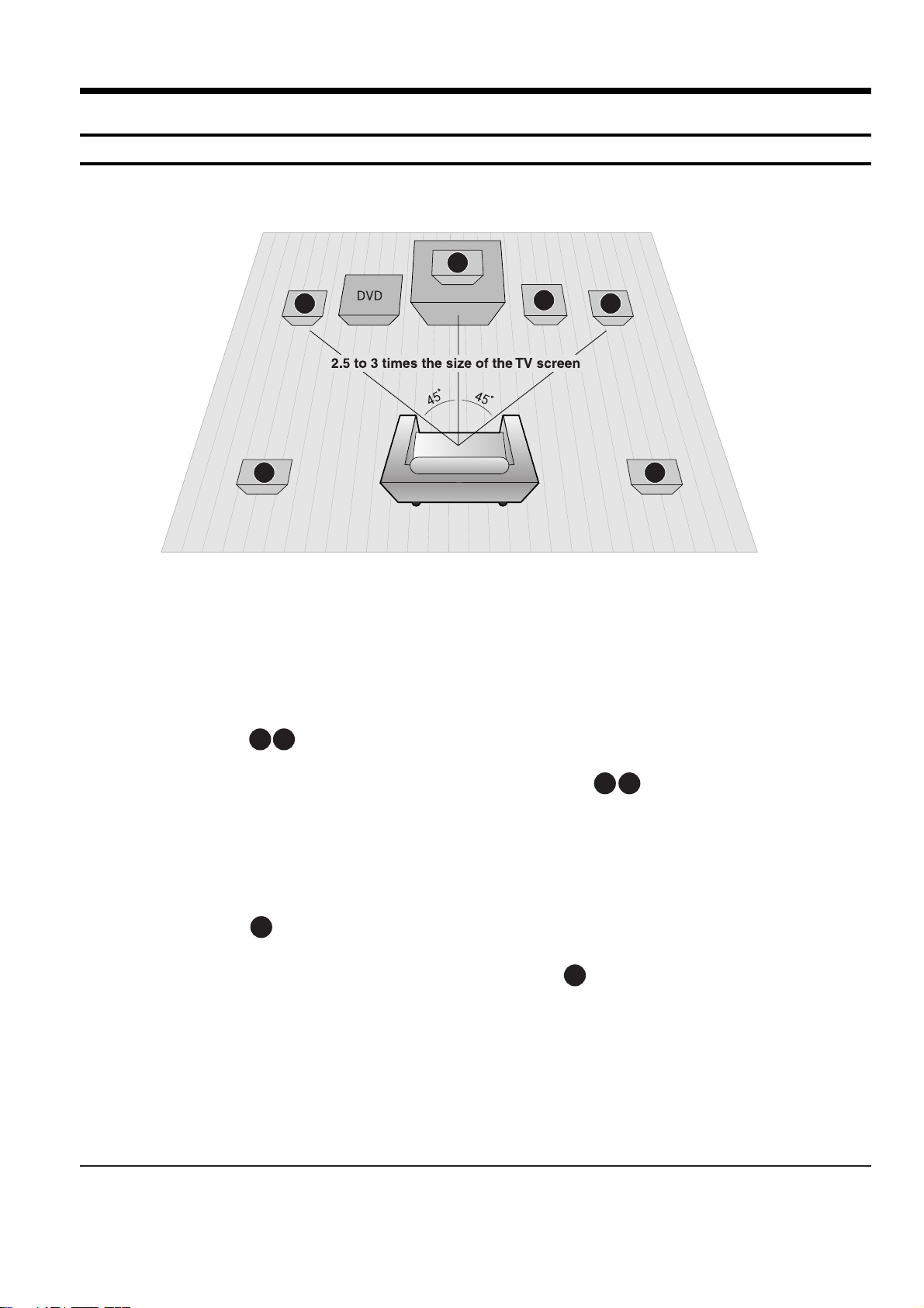
3. Product Functions
1. SPK connection
RSLS
C
L
SW
R
Rear Speakers
•
Place these speakers behind your listening position.
•
If there isn't enough room, place these speakers to face each other.
•
Place them about 60 to 90cm (2 to 3feet) above your ear, facing
slightly downward.
*
Unlike the front and center speakers, the rear speakers are used
to handle mainly sound effects and sound will not come from
them all the time.
Subwoofer
•
The position of the subwoofer is not so critical.
Place it anywhere you like.
•
Usually, it is placed by a corner near the front speakers.
Front Speakers
•
Place these speakers in front of your listening position, facing inwards (about 45°) toward you.
•
Place the speakers so that their tweeters will be at
the same height as your ear.
•
Align the front face of the front speakers with the
front face of the center speaker or place them
slightly in front of the center speakers.
Center Speaker
•
It is best to install it at the same height as the front
speakers.
•
You can also install it directly over or under the TV.
Position of the DVD Player
•
Place it on a stand or cabinet shelf, or under
the TV stand.
Selecting the Listening Position
The listening position should be located about 2.5 to 3
times the distance of the TV's screen size away from the
TV. Example: For 32" TVs 2~2.4m (6~8feet)
For 55" TVs 3.5~4m (11~13feet)
R
L
C
RS
LS
SW
3-2 Samsung Electronics
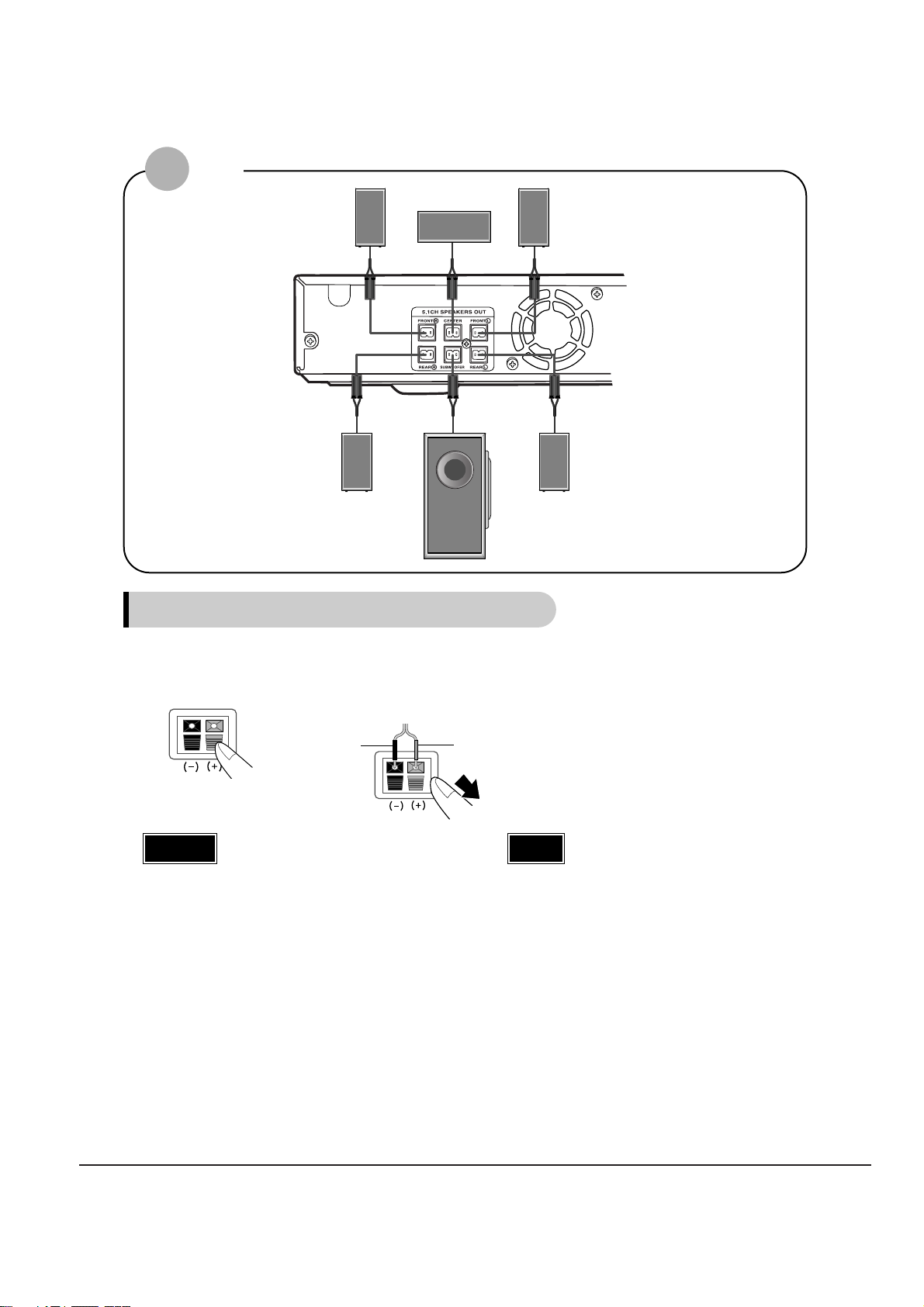
Connecting the Speakers
Black
Press down the terminal
tab on the back of the
speaker.
1
Insert the black wire into the
black terminal (–) and the red
wire into the red (+) terminal,
and then release the tab.
2
Connect the correct color speaker cable
to the same color speaker output terminal
on the rear of the subwoofer, according
to the polarity markings (+/–).
Example: Connect the green center speaker cable
to the green center speaker output terminal on the rear of the subwoofer according to the polarity markings (+/–).
3
Red
•
Do not let children play with or near the speakers.
They could get hurt if a speaker falls.
•
When connecting the speaker wires to the speakers,
make sure that the polarity (+/–) is correct.
Caution
•
If you place a speaker near your TV set,
screen color may be distorted because of
the magnetic field generated by the speaker. If this occurs, place the speaker away
from your TV set.
Note
Front Speaker (R)
Rear Speaker (R)
Subwoofer
Center Speaker
Front Speaker (L)
Rear Speaker (L)
HT-Q20
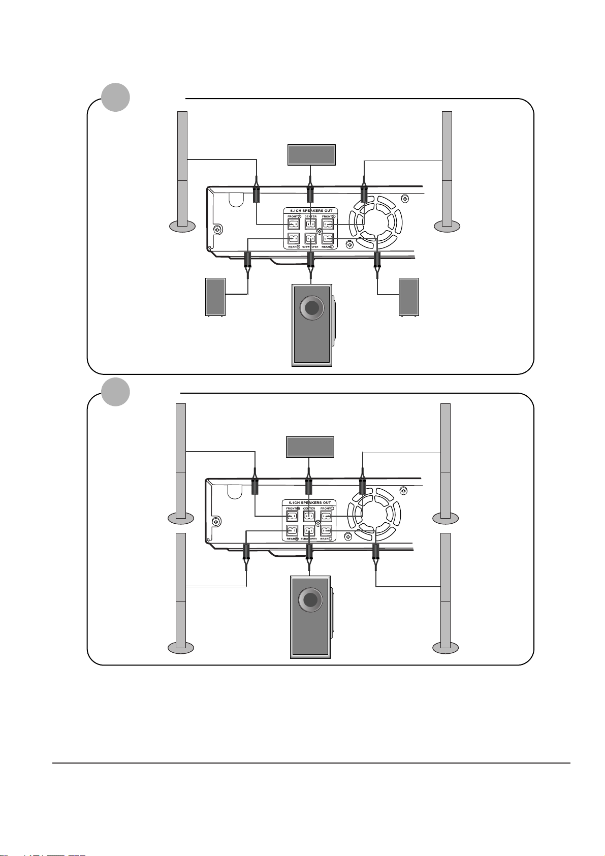
Samsung Electronics 3-3
Front Speaker (R)
Rear Speaker (R)
Subwoofer
Center Speaker
Front Speaker (L)
Rear Speaker (L)
HT-TQ22
HT-TQ25
Front Speaker (R)
Rear Speaker (R)
Subwoofer
Center Speaker
Front Speaker (L)
Rear Speaker (L)
3-4 Samsung Electronics
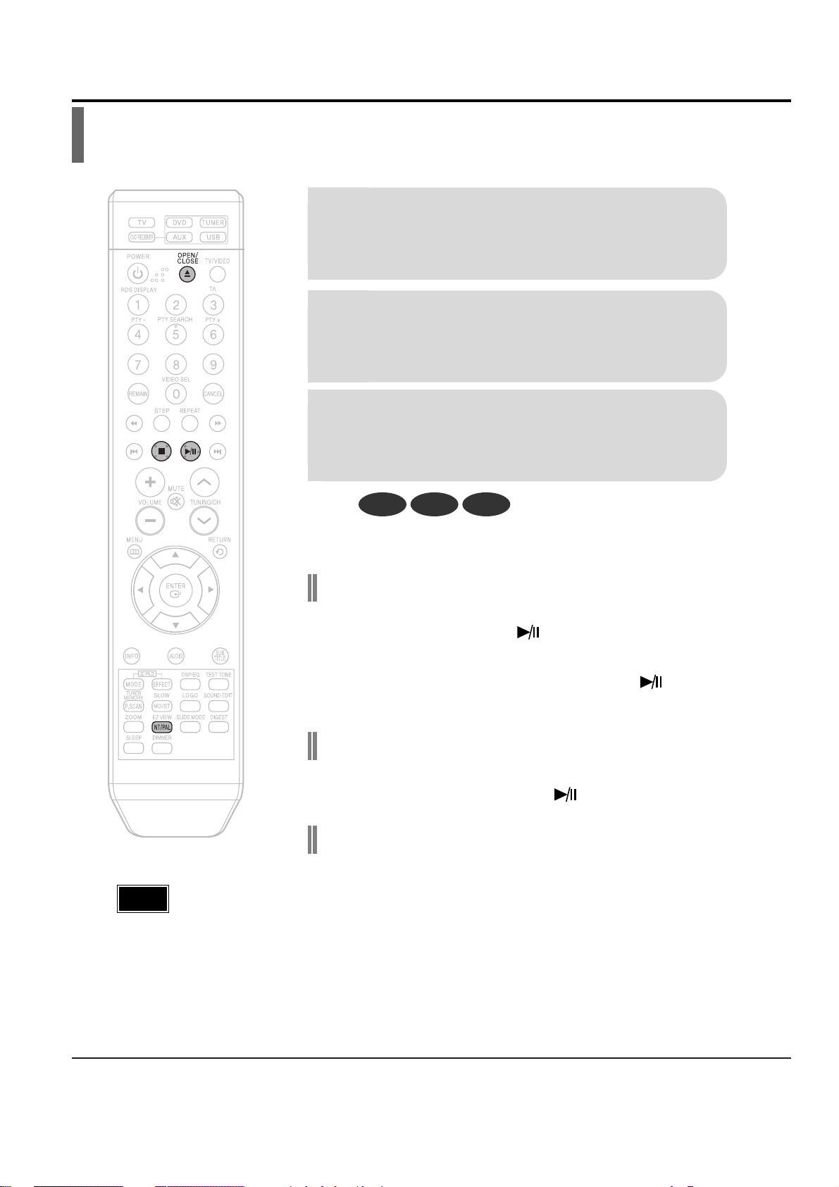
2. Main Functions
Disc Playback
To stop playback, press STOP during playback.
•
If pressed once, “PRESS PLAY” is displayed and the stop position will be
stored in memory. If PLAY/PAUSE ( ) button or ENTER button is
pressed, playback resumes from the stop position. (This function works only
with DVDs.)
•
If pressed twice, “STOP” is displayed, and if PLAY/PAUSE ( ) button is
pressed, playback starts from the beginning.
To temporarily pause playback, press PLAY/PAUSE
during playback.
•
To resume playback, press PLAY/PAUSE ( ) button again.
DVD VCD CD
•
Playback starts automatically.
Selecting the Video Format
Press and hold NT/PAL button on the remote controller for over 5 seconds
while the power is turned off.
•
By default, the video format is set to "PAL".
•
"NTSC" or "PAL " will appear in the display. At this time, press the NT/PAL button
shortly to select between "NTSC" and "PA L".
•
Each country has a different video format standard.
•
For normal playback, the video format of the disc must be the same as the video
format of your TV.
2
Load a disc.
•
Place a disc gently into the tray with the disc’s label
facing up.
•
Depending on the content of
the disc, the initial screen may
appear different.
1
Press OPEN/CLOSE button to open the
disc tray.
3
Close the compartment by pressing the
OPEN/CLOSE button again.
Note

Samsung Electronics 3-5
•
Depending on the number of languages on a DVD disc, a different
audio language (ENGLISH, SPANISH, FRENCH, etc.) is selected each
time the button is pressed.
2
Press Cursor ,
buttons or numeric buttons to select the
desired audio language.
1
Press INFO button
twice.
SP 2/3
FR 3/3
Audio Language Selection Function
DVD
Selecting Audio Language

3-6 Samsung Electronics
EN 1/3 EN 01/ 03
OFF
SP 02/ 03
FR 03/ 03
OFF / 03
•
To operate this function, you can also press the Select AUDIO or Select SUBTITLE buttons on the remote control.
•
Depending on the disc, the Subtitle and Audio Language functions
may not be available.
Subtitle Language Selection Function
DVD
2
Press Cursor
button to move to
SUBTITLE ( )
display.
1
Press INFO button
twice.
3
Press Cursor
button or numeric
buttons to select
the desired subtitle.
Note
Selecting Subtitle Language
Samsung Electronics 3-7
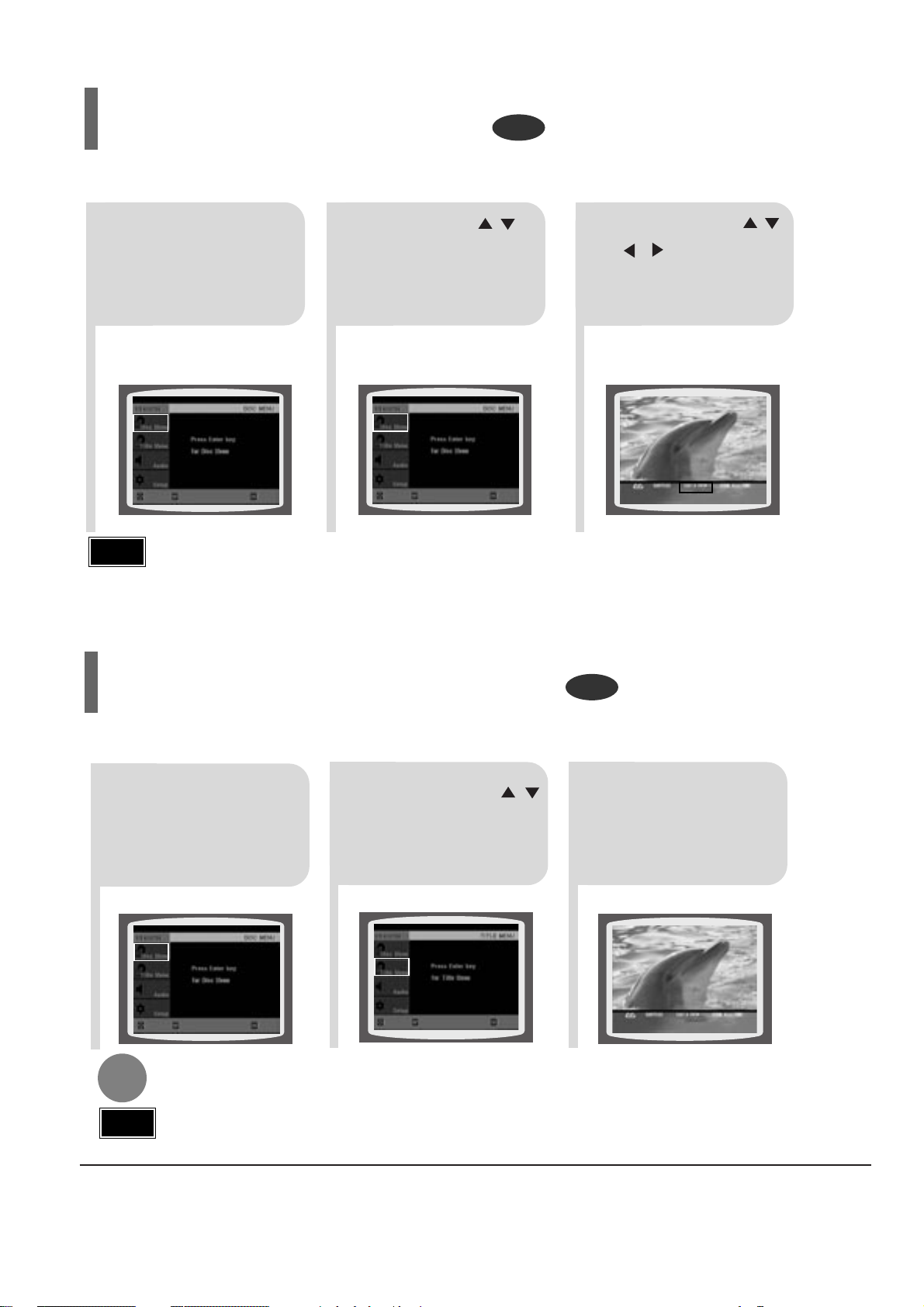
2
Press Cursor ,
button to move to
‘Title Menu’.
DVD
1
In Stop mode,
press MENU button.
3
Press ENTER button.
•
The title menu appears.
Press MENU button to exit the setup screen.
DVD
2
•
When you select Disc Menu and it is not
supported by the disc, the "This menu is not sup-
ported" message appears on the screen.
1
In Stop mode,
press MENU
button.
Press Cursor ,
buttons to move to
‘DISC MENU’ and then
press ENTER button.
3
•
Press ENTER button.
Press Cursor ,
, buttons to
select the desired
item.
You can use the menus for the audio language, subtitle language, profile, etc.
DVD menu contents differ from disc to disc.
Using Disc Menu
For DVDs containing multiple titles, you can view the title of each movie.
Depending on the disc, the availability of this feature may vary.
Using the Title Menu
•
Title menu display may be different depending on the disc.
Note
ENTERMOVE EXIT
ENTERMOVE EXIT
ENTERMOVE EXIT
ENTERMOVE EXIT
•
When playing a VCD (version 2.),
this toggles between PBC ON
and OFF.
PBC (Playback Control) Function
When playing a VCD (version 2.0), you can select and view various scenes according to the menu screen.
PBC ON: This VCD disc is version 2.0. The disc is played back according to the menu screen.Some functions
may be disabled.When some functions are disabled, select "PBC OFF" to enable them.
PBC OFF: This VCD disc is version 1.1. The disc is played back in the same way as with a music CD.
•
Disc menu display may be different depending on the disc.
Note

3-8 Samsung Electronics
3. New Functions
Fast playback
Skip Forward/Back
During playback, press the button.
•
Goes to the next file whenever you press button, if there are over
2 files in the disk.
•
Goes to the previous file whenever you press button, if there are
over 2 files in the disk.
To play back the disc at a faster speed,
press or during playback.
•
Each time you press either button, the playback speed will change as
follows:
2x ➞ 4x ➞ 8x ➞ 32x ➞ Normal.
•
DIVX file can be zoomed only in ZOOM X2 mode.
•
DivX files have .Avi file extensions, however, not all .Avi files are DivX
and may not be playable in this unit.
Note
Zoom Function
2
Press Cursor , ,
, buttons to move
to the area you want
to enlarge.
1
Press ZOOM
button.
•
Each time you press the button,
your selection will toggle between
“ZOOM X2” and “ZOOM OFF”.
DivX Playback
5 Minute Skip function
During playback, press the , button.
•
Playback skips 5 minutes forward whenever you press button.
•
Playback skips 5 minutes back whenever you press button.
The functions on this page apply to DIVX disc playback.
Samsung Electronics 3-9
•
" " is displayed when there is one supported audio item in the disc.
Note
Format AVI WMA
Surpported Versions DivX3.11 ~ 5.1 V1/V2/V3/V7
Press the SUBTITLE button.
•
Each time you press the button, your selection will toggle between “SUBTITLE ON” (1/1, 1/2 ...) and
“SUBTITLE OFF”.
•
If the disc has only one subtitle file, it will be played automatically.
Subtitle Display
Press the AUDIO button.
•
Each time you press the button, your selection will toggle between “AUDIO ON” (1/1, 1/2 ...) and
“”.
Audio Display
DivX
(Digital internet video eXpress)
DivX is a video file format developed by Microsoft based on the MPEG4 so as to provide audio, and
video data over the Internet in real-time.
MPEG4 is used for video encoding and MP3 for audio encoding so that the users can watch a movie
in DVD-quality video and audio.
1. Supported Formats
•
This product only provides the following media formats. If both of the video and audio formats are not
supported simultaneously, the user may experience problems such as broken image or no sound.
2. Caption Related
•
To use the caption function, save the caption file (*.smi) in the same file name as that of the DivX
media file (*.avi) within the same folder.
Example. Root Samsung_Bluetek_007CD1.avi
Samsung_Bluetek_007CD1.smi
•
Up to 60 alphanumeric characters or 30 East Asian characters (2 byte characters such as Korean and
Chinese) for the file name.
●
Supported Video Formats
Format MP3 WMA AC3 DTS
Bit Rate 80~384kbps 56~128kbps 128~384kbps N/A
Sampling Frequency
44.1khz 44.1/48khz N/A
•
Aspect Ratio: Although default DivX resolution is 640*480 pixels (4:3), this product supports up to
720*480 pixels (16:9). It will not be supported when the screen resolution is higher than 800.
●
Supported Audio Format
 Loading...