

Page 1
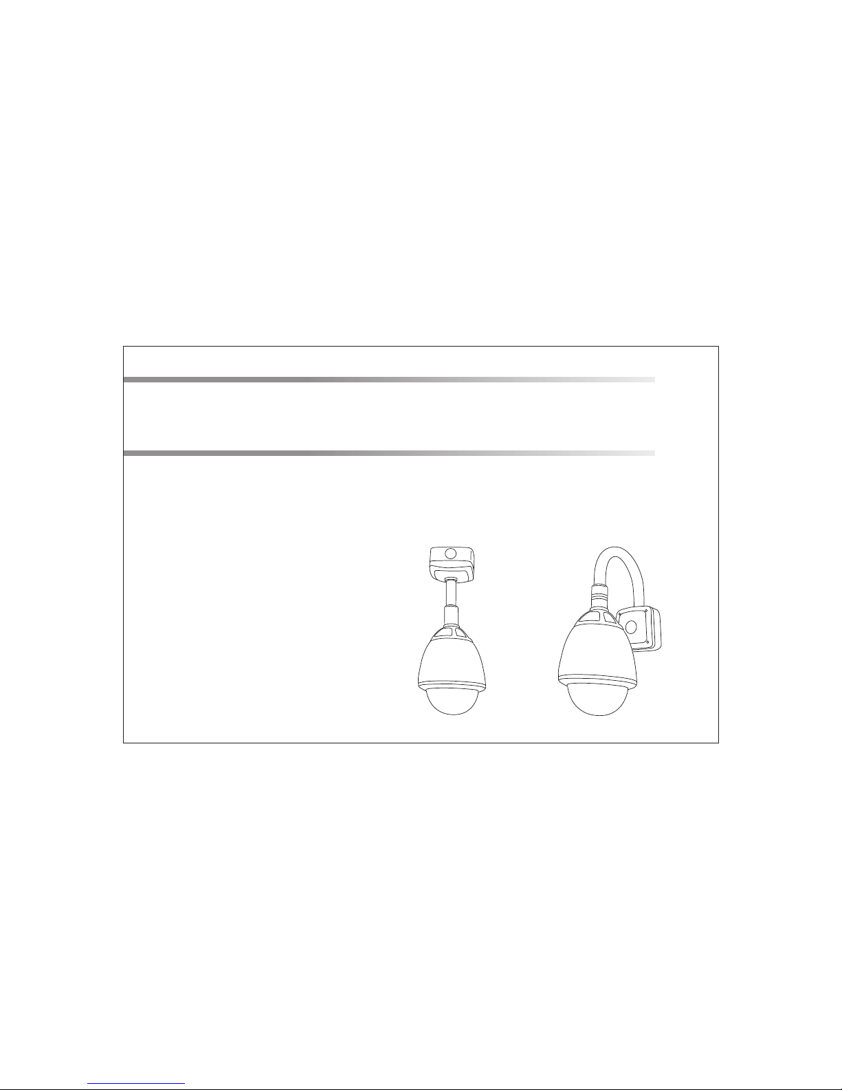
23x High Speed Dome System
User Manual
Page 2

Contents
Before inst all ing
Key feature s
Configure , fix a nd wi re
Basic speed d ome o per ati on
Programmi ng th e spe ed do me
Using the spe ed do me fe atu res
Parts and dim ens ion s
Wiring sche mat ic
Specifica tio ns
Installer n ote s
1
2
3
6
7
13
14
15
16
17
Page 3
Before installing
1
!
·Installation should be carried out only by qualified personnel and in accordance with
any wiring regulations in force at the time.
·The speed dome is heavy and could cause injury if not correctly mounted in
accordance with these instructions. Use only the fittings supplied with the speed
dome and ensure that all lanyard safety cables are connected correctly during
installation.
·Adequate protection against lightning strikes and power surges must be installed to
prevent damage to the speed dome.
·Any safety warnings on the product and in these instructions must be adhered to.
·If cleaning is necessary, disconnect power to the speed dome first. Do not use
abrasive cleaners, as these will cause damage to the cover and cause poor image
quality. Use a damp cloth to gently clean the dome cover and dry off with a soft
clean cloth.
·Do not use any brackets, mounts or other accessories not specifically designed for
use with this speed dome.
Do not attempt to service or repair the speed dome as opening or removing covers
may expose dangerous voltages or other hazards. Refer all servicing to qualified
service personnel.
Page 4

Key features
2
Presets
Up to 127 sets of positional and zoom level information can be stored as
presets. These can be called manually by the operator, automatically by an
alarm input, or grouped to form a sequence of actions to run automatically.
Each preset can also be programmed with the following:
Pattern tours
Any dome movement can be recorded - and subsequently played back - as
four separate pattern tours. These can be played back individually or
grouped to form a sequence of tours.
Scan between 2 presets
Scan is a useful feature when, for example, the operator wishes to ‘patrol’ a
perimeter fence. If one preset is defined at one end of the fence and a
second preset is defined at the other, the scan function will smoothly and
accurately move from one end to the other and then back again in a
repeating sequence. Speed can be adjusted as necessary and up to 8 scan
functions can be defined.
Group function
The group function is a powerful feature which allows the operator to define
a sequence of speed dome actions to form an automatic patrol sequence.
Actions can be a mix of preset positions, pattern tours and scan functions.
Up to 8 groups can be defined and each group can have up to 20 actions
which repeat indefinitely until interrupted by the operator or an alarm input.
Specific parameters such as preset speed, dwell time and action loop can
also be specified
Alarm action - relay outputs can be triggered when particular presets are
called
Title - each preset can be titled with up to 10 characters so that zones can
easily be identified
Privacy zones
By defining a privacy zone, sensitive scenes such as windows can be
masked off so they cannot be viewed by the operator. Up to 8 privacy
zones can be defined. Privacy zone size adjusts automatically depending
on the speed dome zoom level.
Alarm inputs and outputs
This speed dome has 8 alarm inputs and 4 alarm outputs. Any alarm input
can be set to call a predefined preset, scan function, pattern or group. Any
preset can be configured to activate any or all of the alarm outputs. For
example, a PIR detector connected to alarm input 1 could call preset 7 to
view that particular scene whilst activating an external lamp connected to
relay 1 and an external siren connected to relay 3.
On Screen Display (OSD)
The operator can choose if any or all of the following information is
displayed on screen during normal speed dome operation.
Time and Date
The speed dome also has a full on screen menu setup allowing quick and
easy configuration of all the speed dome features.
Powerful park function
The speed dome can be configured to run a specified VST function, pattern
tour, group or preset after a defined period of inactivity.
·
Preset status and title
Speed dome position coordinates and zoom level
Alarm I/O status
Speed dome ID
Page 5
3
Configure, fix and wire
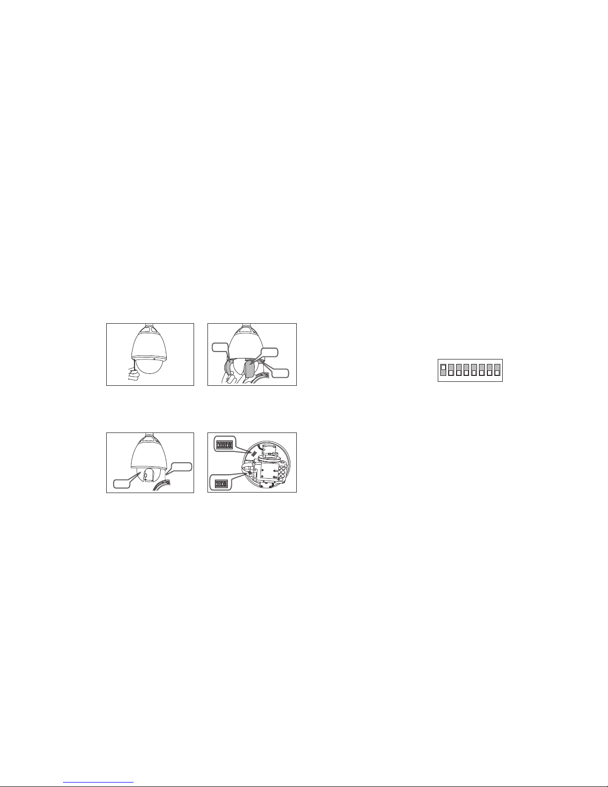
1. Remo ve th e foa m pac king pieces
3. Reas sem ble t he sp eed dome
Proto col & B aud r ate D IP sw itc h table
Speed d ome I D DIP s wit ch ta ble
2. Chan ge pr oto col , baud rate and ID if r equ ire d
Bef ore pro ceedi ng with i nstal latio n, the sp eed dom e foam pa cking
pie ces mus t be remo ved. Re move th e outer d ome cov er with t he tool
sup plied a nd care fully r emove t he foam p ackin g piece s. When
han dling t he dome c over, al ways we ar the gl oves su pplie d to avoi d
get ting fi ngerp rints o n the out er dome c over.
Ref it the bl ack inn er dome c over an d outer d ome cov er. If the
lan yard sa fety wi re was re moved , it must b e refit ted bef ore the d ome
cov er is fix ed.
The f actor y defau lt sett ing is Pe lco D, 24 00, ID 1. S kip to se cti on
3 if th ese set tings m atch yo ur cont rol equ ipmen t
Foam
Foam
Cover
Lanyard
1. Wearing the gloves and using the supplied
tool, remove the outer dome cover.
1. Carefully unclip the black inner dome 2. Locate the dip switches and set protocol
and ID according to the table opposite.
2. Remove the foam pieces from the camera
module.
Foam
12 3 4 56 7 8
12 3 4 56
ON
ON
ID
Protocol
Not e: ID 0 sho uld not b e used. W here mu ltipl e speed d omes
are c onnec ted, a un ique ID m ust be as signe d to each o ne.
Dip s witch es 9-10 a re rese rved an d must no t be chan ged.
1 2 3 4 5 6 7 8
ON
Fac tory de fault
swi tch pos ition s
Spe ed dome I D is set
usi ng stan dard
bin ary not ation
1 2 3 Pro tocol /Rate
OFF O FF OFF Pe lcoD, 4800 bp s
OFF O N OFF AD,4 800 bps
ON ON O FF VC,9 600 bps
OFF O FF ON Pel coP,9600 b ps
ON OF F ON Pelc oP,4800 bp s
OFF O N ON Pelc oD,96 00 bps
ON ON O N Pelco D,240 0 bps
Not e: Dip sw itche s 4-6 are r eserv ed
and m ust not b e chang ed.
1 2 3 4 5 6 7 8 9 10 DI P
1 2 4 8 16 32 6 4 128 – – VAL/I D
ON OF F OFF OFF O FF OFF OF F OFF
OFF O N OFF OFF O FF OFF OF F OFF – – 2
ON ON O FF OFF OF F OFF OFF O FF – – 3
OFF O FF ON OFF O FF OFF OF F OFF – – 4
ON OF F ON OFF OF F OFF OFF O FF – – 5
OFF O N ON OFF OF F OFF OFF O FF – – 6
ON ON O N OFF OFF O FF OFF OF F – – 7
OFF O FF OFF ON O FF OFF OF F OFF – – 8
– – – – – – – – – – –
ON ON O N ON ON ON ON O N 255
– – 1
Page 6
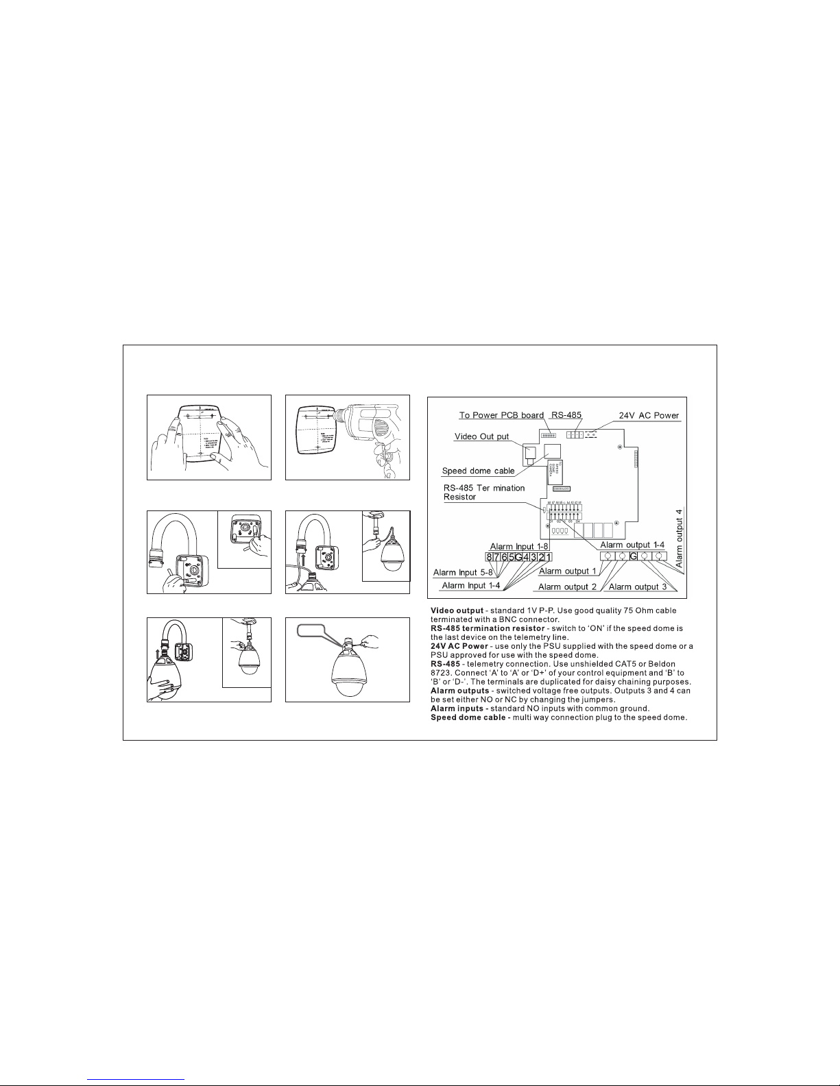
4. Fix th e bra cke t
1. Fix the supplied mounting template, taking
account of any pipework, cables, overhangs
etc. that may obstruct the bracket once fitted.
3. Remove the junction box cover. Using the
supplied bolts and tool, firmly fix the bracket.
Pendent option
Pendent option
Pendent option
5. Bring the speed dome up to the bracket.
6. Tighten the three screws to fix the speed
dome and ensure the lanyard safety chain is
properly connected.
4. Feed the speed dome cable through the
bracket.
2. After making suitable checks for buried
pipes and cables, drill fixing holes suitable for
the bolts supplied with the speed dome.
Lanyard
B A
O1
O2 O3
O4
A2A1 A3A4 G
B A ~ ~
A6
A5
A7
A8
RS-485 Termination Resistor
Video output
Speed dome cable
RS-485
24V AC Power
Alarm Input 1-8
Alarm Output 1-4
G
1
2
3
4
Alarm Input 1-4
5 6 7 8
Alarm Input 5-8
Alarm Output 4
Alarm Output 3
ON
1
Alarm Output 2
Alarm Output 1
Jun ction b ox PCB de tail
4
NO NCNO NC
Alarm 3 Output State
Alarm 4 Output State
NC or NO
NC or NO
5. Wire up the j unc tio n box
1
2
3
4
Page 7
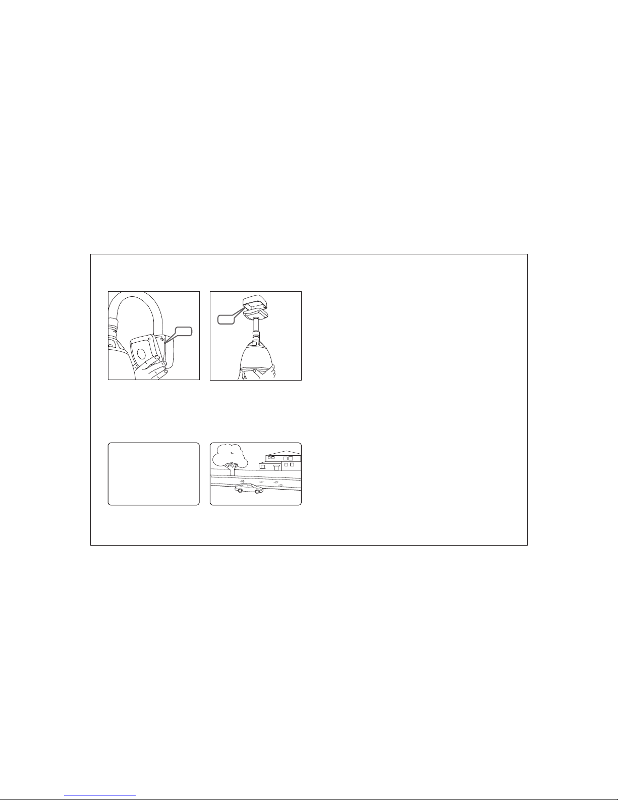
5
6. Comp let e the i nst all If ther e’s a pr oblem at this sta ge. ..
7. Verif y bas ic op era tion
1a - wall bracket option. After making all the
connections to the PCB, fit the junction box
cover with the four screws.
…work through the logical steps below to determine and rectify the problem
No picture - check the PCB to make sure the red power LED is lit. If not, check that the PSU is
correctly connected and has power. If you have a test meter, verify that the output of the PSU is
approximately 24V AC.
If the power LED is lit, check the BNC crimp connection is correctly made at both the PCB end and
the DVR / monitor / matrix end. A portable test monitor connected directly to the video output of the
speed dome is also a useful test - if a picture is displayed, double check the BNC connections and
the signal cable used.
No PTZ control - check that the control equipment you are using is compatible with the speed
dome and is configured to match the speed dome settings correctly.
If dip switches were changed on the speed dome, check the power on self test screen to ensure
that protocol, ID and baud rate are as expected.
If the settings match, you should check the polarity of the connections, both on the control
equipment and the speed dome. If you suspect there is a polarity issue, swap the A & B wires at the
speed dome to see if this resolves the problem.
Check also that there are no other telemetry devices on the system with the same ID as the speed
dome. If in doubt, connect the speed dome directly to the PTZ controller and isolate all other
equipment.
1. After carefully checking the installation,
including all cable connections, apply power to
the dome and check that the startup and self
test screen is displayed.
2. After the self test is complete, the dome
starts normal operation. Verify that there is
basic PTZ control from your control equipment.
Note: when fixing the cover to the junction box, ensure that the seal is also
fitted properly and that none of the cables are trapped
1b - pendent option. After making all the
connections to the PCB, raise the dome
assembly to the junction box, connect the
dome cable to the PCB and fix with the four
screws.
HI GH S PE ED D OM E
-- -- -- -- -- --- -- -- -- -- -- FI RM WA RE V ER
CO LO UR S YS TE M
PR OT OC OL
AD DR ES S
BA UD R AT E
DA TA M EM OR Y
ZO OM M OD UL E
AL AR M I/ O
HO ME T EA CH IN G..
O: -- --
I: 12 34 56 78
32 5/ 37 /x 1
: 1. 0S 18 V
: PA L
: PE LC O- D
: 1
: 24 00
: OK
: OK
: OK
EN D
WA IT .. .
Seal
Seal
07 /J AN /2 00 7
14 :4 6: 46
CA M 1
Page 8
6
0 7/ J AN / 20 0 7
0 9: 3 7: 1 5
C AM 1
O :- 2 3-
I :1 2 34 5 67 8
3 07 / 46 / x3
PR ES ET 3
P RE S ET 3
PA RK IN G BA Y 1
R EC E PT I ON
Basic speed dome operation
Progr amm ing , cal ling and deleti ng pr ese ts
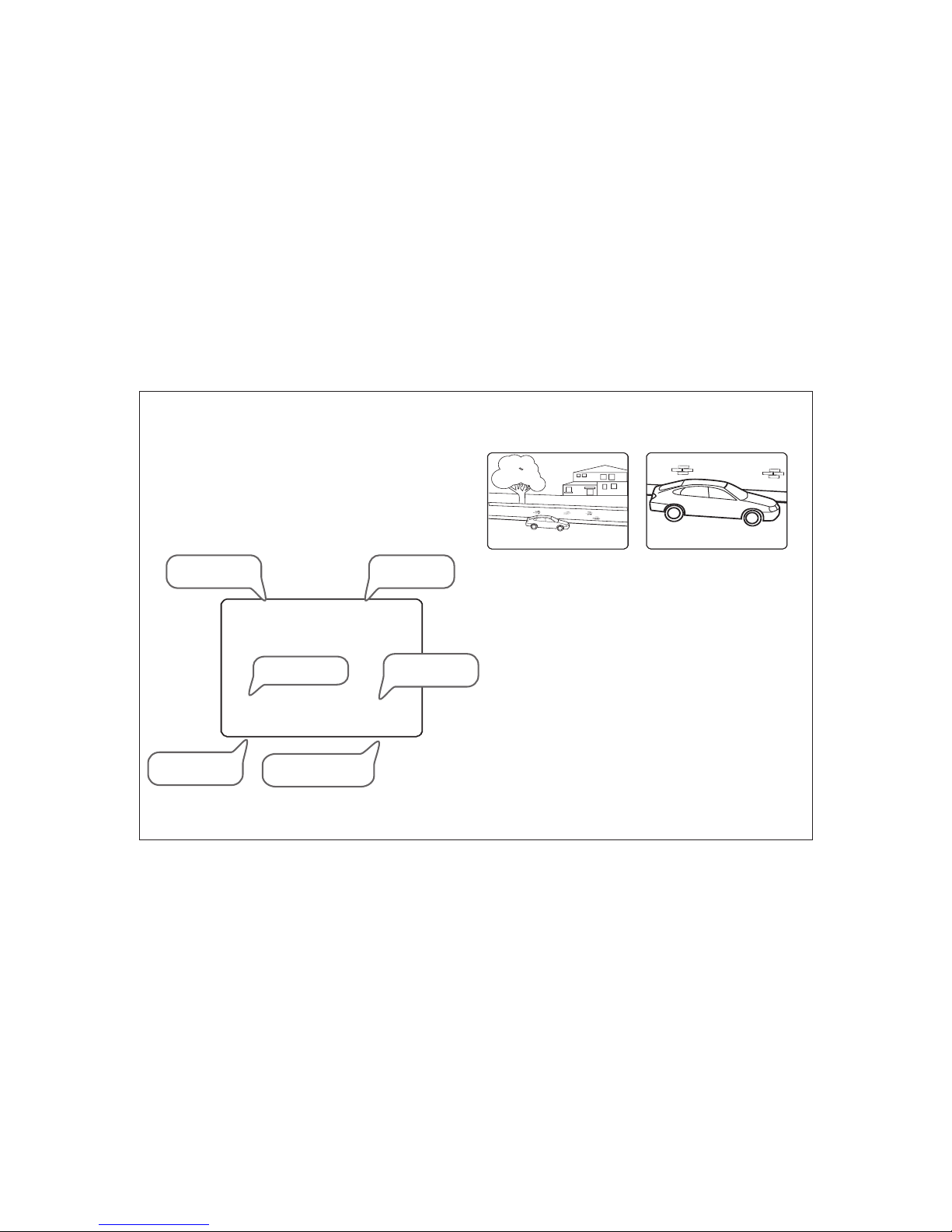
Under sta ndi ng th e On Screen Displ ay (O SD)
SE T PR ES ET 1
The re are ma ny diff ere nt PTZ k eyb oard s and D VR sys tem s capa ble
of co ntrol ling th is spee d dome, a nd it wou ld be imp ossib le to
des cribe t hem all h ere. Th ere fore , exa mple s giv en in th e fol lowi ng
pag es are ba sed on th e more po pular c ontro l equip ment av ailab le.
Whi lst the p rinci ples of o perat ion are t he same , regar dless o f the
con trol eq uipme nt used , refer ence ma y need to b e made to t he
man ual sup plied w ith you r parti cular c ontro l equip ment.
To program a preset position, move the speed
dome to the desired scene and zoom level
and press:
SET - XXX - ENTER
Where XXX is a preset number between 1 &
128 (but note that preset 95 is reserved and
cannot be used). Confirmation is displayed on
the OSD.
To delete a preset position, press:
CLEAR - XXX - ENTER
Where XXX is a preset number between 1 &
128 (but note that preset 95 is reserved and
cannot be used). The preset position is
cleared from memory.
To reprogramme a preset position, follow the
steps for programming a preset - it is not
necessary to delete the old preset position first
PRESET LABEL: If defined,
is displayed when a preset
position is called
CAMERA ID: Shows the
current ID as defined by the
dip switch settings
ALARM I/O: Shows which
alarm inputs and outputs are
active
DATE/CLOCK: Shows
current time and date
PTZ INFORMATION: The current
pan/tilt position in degrees and
the current zoom level
ACTION TITLE: Shows
current speed dome
action
To go to a preset position thats already
been programmed, press:
SHOT - XXX - ENTERXXX - Preset
Where XXX is a preset number between 1 &
128 (but note that preset 95 is reserved and
cannot be used). The speed dome moves to
the preset position. Confirmation and preset
title (if defined) is displayed on the OSD.
O: -- --
I: 12 34 56 78
32 5/ 37 /x 1
O: -- --
I: 12 34 56 78
32 5/ 37 /x 3
07 /J AN /2 00 7
12 :3 8: 05
CA M 1
07 /J AN /2 00 7
12 :4 2: 22
CA M 1
Page 9
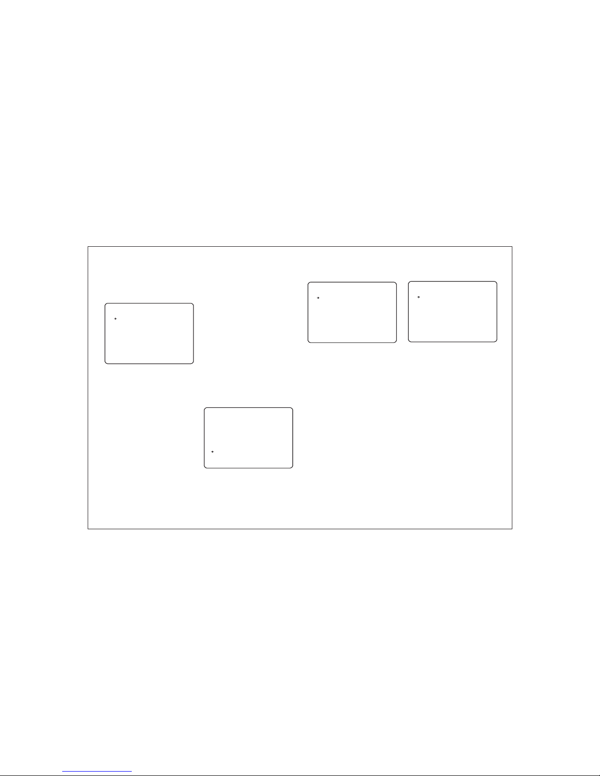
Displ ay se tup
Set dat e/t ime
Syste m inf orm ati on
The s peed do me setu p menu al lows th e opera tor to cu stomi se and
pro gram al l aspec ts of spe ed dome o perat ion. All m enu set tings a re
ret ained i n non-v olati le memo ry so if po wer is lo st to the s peed do me
for a ny reas on, all s ettin gs will b e retai ned.
MA IN ME NU
-- --- -- --- -- --- --- -- --- -- --- -
<S YST EM I NFO RM ATI ON>
<D ISP LA Y SET UP >
<D OME C AM ERA S ET UP>
<A LAR M SE TUP >
<P ASS WO RD SE TU P>
<H ELP >
EX IT
<S YST EM I NIT IA LIS E>
DI SPL AY S ETU P
-- --- -- --- -- --- --- -- --- -- --- -
CA MER A ID
AC TIO N TI TLE
PT Z INF OR MAT IO N
PR ESE T LA BEL
AL ARM I /O
DA TE/ TI ME
<S ET DA TE /TI ME >
<P RIV AC Y ZON E>
BA CK
EX IT
SE T DAT E/ TIM E
-- --- -- --- -- --- --- -- --- -- --- -
DA TE 07 /J AN/ 20 07
TI ME 14 :3 7:1 5
BA CK
EX IT
SY STE M IN FOR MA TIO N
-- --- -- --- -- --- --- -- --- -- --- -
FI RMW AR E VER
CO LOU R SY STE M
PR OTO CO L
AD DRE SS
BA UD RA TE
BA CK
EX IT
To access the speed dome setup menu, key:
SHOT - 95 - ENTER
To navigate the main menu, move the joystick
up / down to choose a menu item or change
settings within a menu item.
To enter a menu item or confirm a new setting,
key: NEAR
To exit a menu item or cancel a new setting,
key: FAR
Where a menu item is surrounded by
brackets, it indicates that there is a sub menu.
Where a menu screen shows EXIT, selecting
this option will exit the menu and the speed
dome will return to normal operation. Where a
menu screen shows BACK, selecting this
option will return to the higher menu level.
The main menu has five options:
<SYSTEM INFORMATION> - Provides
information such as firmware version, protocol
and ID values as defined by the dip switch
settings.
<DISPLAY SETUP> - Allows the operator to
specify which On Screen Display information
is shown during normal operation. Also allows
privacy zones to be defined and time/date to
be changed
<DOME CAMERA SETUP> - Allows all
operating features of the speed dome to be
programmed and managed. Also allows
settings for the camera module to be changed
<PASSWORD SETUP> - Allows a password
to be set to protect the speed dome setup
<SYSTEM INITIALISE> - Allows various
speed dome settings to be reset to factory
defaults
From the main menu, use the joystick to
highlight SYSTEM INFORMATION and key:
NEAR
To return to the main menu, highlight BACK
and key: NEAR
To exit the setup menu completely, highlight
EXIT and key: NEAR
From the main menu, use the joystick to
highlight DISPLAY SETUP and key: NEAR
CAMERA ID (ON / OFF) - shows camera ID
according to the DIP switch settings, eg
CAM 1.
ACTION TITLE (ON / OFF / AUTO) - shows
current speed dome action, eg PRESET3.
PTZ INFORMATION (ON / OFF / AUTO) shows the current pan / tilt position in degrees
and the current zoom level.
PRESET LABEL (ON / OFF / AUTO) - shows
preset title (if defined) when a preset is called.
ALARM I/O (ON/OFF) - shows real time
status of the alarm inputs and outputs.
<SET DATE/TIME) - sub menu to change the
date and time
<PRIVACY ZONE> - sub menu to setup the
speed dome privacy zones
Highlight the item to modify and key: NEAR
Use the joystick to change the setting and key:
NEAR to save or: FAR to cancel.
Note: If the auto option is chosen, the relevant
information is displayed for a few seconds
before disappearing.
From the display setup menu, use the joystick
to highlight SET DATE/TIME and key: NEAR
Highlight the item to modify and key: NEAR
Move the joystick up and down to change an
individual value and left and right to move to
the previous / next value
Key: NEAR to save or: FAR to cancel.
: 2. 1SY 23 V
: PA L
: PE LCO -D
: 00 1
: 24 00
ON
AU TO
ON
AU TO
ON
ON
7
Programming the speed dome
Page 10
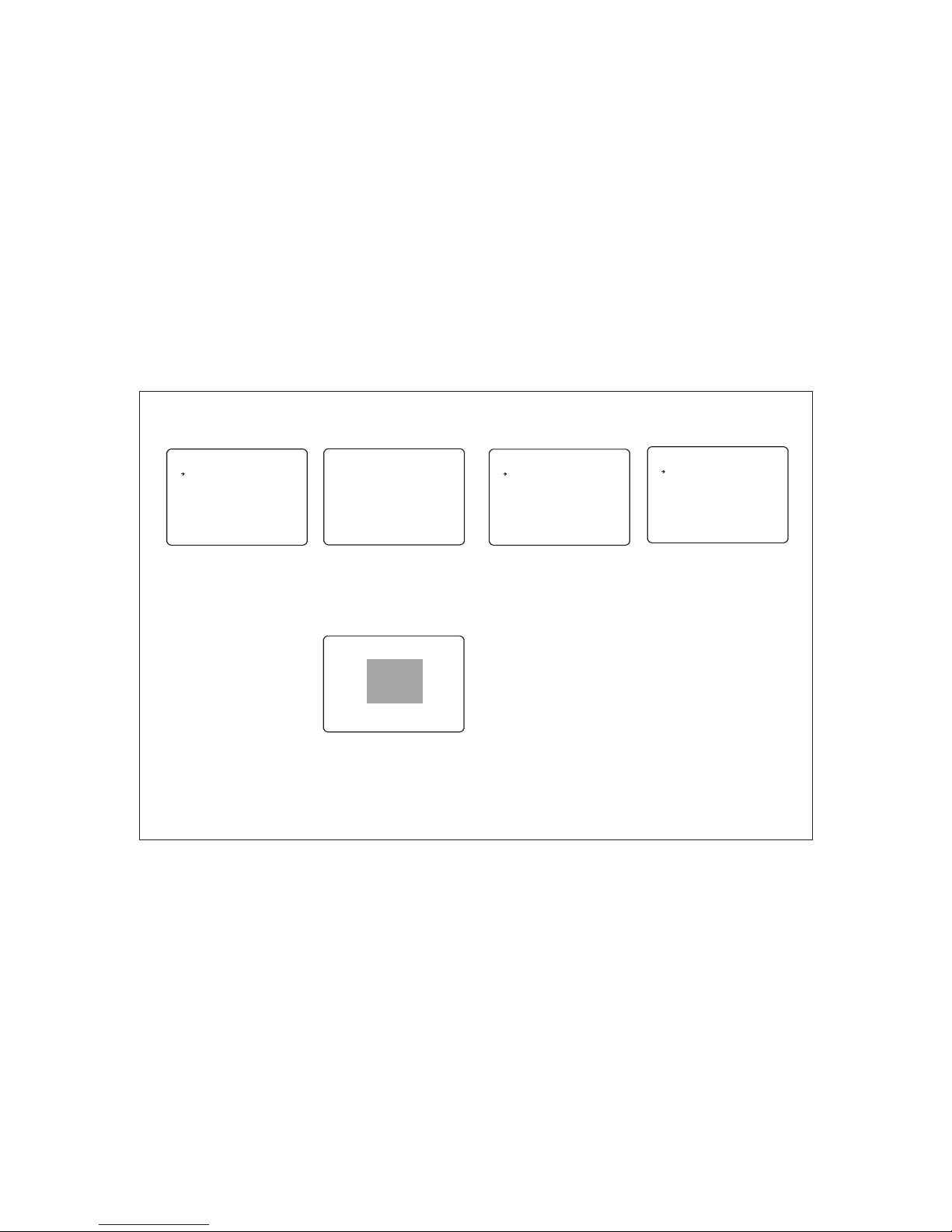
CA MER A SE TUP 1
-- --- -- --- -- --- --- -- --- -- --- -
FO CUS M OD E
CO LOU R
<W HIT E BA LAN CE >
<A E MOD E>
BA CK
EX IT
DI GIT AL Z OOM
DO ME CA ME RA SE TU P
-- --- -- --- -- --- --- -- --- -- --- -
<C AME RA S ETU P1 >
<M OTI ON S ETU P>
<P RES ET S ETU P>
<S CAN S ET UP>
<P ATT ER N SET UP >
BA CK
EX IT
<C AME RA S ETU P2 >
<G ROU P SE TUP >
<S CHE DU LE SE TU P>
From the main menu, use the joystick to
highlight DOME CAMERA SETUP and key:
NEAR
<CAMERA SETUP1>,
- setup of specific camera module features.
<MOTION SETUP> - setup of the pan / tilt /
zoom operation of the speed dome, park
action configuration, and configuration of the
alarm inputs.
<PRESET SETUP> - full management and
programming of individual presets.
<SCAN SETUP> - full management and
programming of SCAN functions.
<PATTERN SETUP> - full management and
programming of pattern tours.
Highlight the setup menu required and key:
NEAR
Remember: A menu item surrounded by
brackets shows it has a sub menu.
<CAMERA SETUP2>
<GROUP SETUP> - full management and
programming of group functions.
<SCHEDULE SETUP> - full management and
programming of Schedule.
From the dome camera setup menu, use the
joystick to highlight CAMERA SETUP1 and
key: NEAR
FOCUS MODE
MANUAL - the operator must focus the
camera manually using the NEAR and FAR
keys.
SEMIAUTO - the camera automatically
focuses during normal PTZ movement but
preset focus information is stored when a
preset is programmed and recalled each time
the preset is called
AUTO - the module auto focuses continually
COLOUR (ON/OFF) - switches the module
between colour and b/w mode
<WHITE BALANCE> - sub menu to change
the white balance settings
<AE MODE> - sub menu to change the auto
exposure settings
DIGITAL ZOOM (ON / OFF) - disables or
enables the 10x digital zoom. When disabled,
the maximum zoom level is 36x (optical).
Dome ca mer a set up
Camer a set up1
8
Priva cy zo ne
Edit zo ne
PR IV ACY Z ON E
-- -- --- -- --- -- --- -- --- -- --- --
ZO NE N O.
ZO NE D ISP LA Y
CL EA R ZON E
<E DI T ZON E>
BA CK
ED IT ZO NE 1
-- --- -- --- -- --- --- -- --- -- --- -
MO VE TO T AR GET P OS ITI ON
[N EAR :S ELE CT /FA R:C AN CEL ]
ED IT ZO NE 1
-- --- -- --- -- --- --- -- --- -- --- -
[L /R: AD JUS T ZO NE WI DTH ]
[U /D: AD JUS T ZO NE HE IGH T]
[N EAR :S AVE / FA R:C ANC EL ]
From the display setup menu, use the joystick
to highlight PRIVACY ZONE and key: NEAR
ZONE NO. (1-8) - shows the privacy zone
currently being modified.
DISPLAY - determines whether the privacy
zone is displayed during normal operation.
<EDIT ZONE> - allows the operator to define
the privacy zone.
Highlight the item to modify and key: NEAR
Use the joystick to change the setting and key:
NEAR to save or: FAR to cancel.
From the privacy zone menu, use the joystick
to highlight EDIT ZONE and key: NEAR
Use the joystick to move the speed dome to
the approximate position and zoom level for
the privacy zone and key: NEAR to select or
FAR to cancel and return to the privacy zone
menu.
1
OF F
CA NCE L
OF F
AU TO
ON
Move the joystick left and right to finely adjust
the width of the privacy zone and up and down
to finely adjust the height.
To save the privacy zone, key: NEAR or key:
FAR to cancel.
Page 11
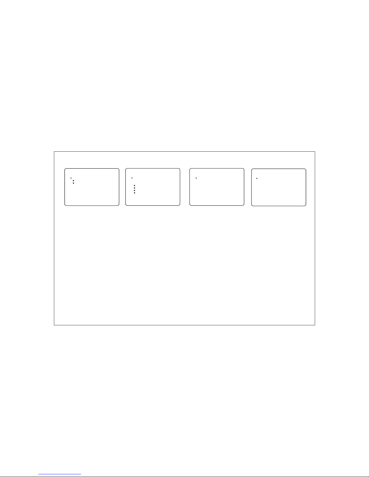
White b ala nce s etu p
Auto ex pos ure s etu p
WB S ETU P
-- --- -- --- -- --- --- -- --- -- --- -
WB M ODE
RE D ADJ US T
BL UE AD JU ST
BA CK
EX IT
AE S ETU P
-- --- -- --- -- --- --- -- --- -- --- -
BL C
DA Y/N IG HT
AE M ODE
IR IS LE VE L
GA IN LE VE L
SH UTT ER S PD
BR IGH TN ESS
BA CK
EX IT
From the zoom camera setup menu, use the
joystick to highlight WHITE BALANCE SETUP
and key: NEAR
WB MODE (AUTO / MANUAL)
AUTO - the speed dome determines the
optimum white balance settings for a given
scene
MANUAL - the operator can adjust white
balance settings manually
RED ADJUST - in manual mode, the red
colour content can be adjusted
BLUE ADJUST - in manual mode, the blue
colour content can be adjusted
Highlight the item to modify and key: NEAR
Use the joystick to change the setting and key:
NEAR to save or: FAR to cancel.
From the zoom camera setup menu, use the
joystick to highlight AUTO EXPOSURE
SETUP and key: NEAR
BLC (OFF/ ON) - The operator can select
BLC(Back Light Compensation) mode,
selecting will disable this feature.
DAY/NIGHT (AUTO/DAY/NIGHT) - the
operator can choose to fix the camera in to
DAY (colour) or NIGHT (B&W with IR cut filter
mode). In AUTO mode, the camera switches
between DAY and NIGHT depending on the
surrounding light level
AE MODE - in AUTO mode, the speed dome
determines optimum camera exposure
settings for a given scene. In modes other
than AUTO, the operator can adjust specific
exposure characteristics to suit a particular
scene
Highlight the item to modify and key: NEAR
Use the joystick to change the setting and key:
OFF
AU TO
-- -
-- -
ON
AU TO
AU TO
-- -
-- -
-- -
-- -
CA MER A SE TUP 2
-- --- -- --- -- --- --- -- --- -- --- -
PI C FRE EZ E
PI C FLI P
ZO OM SP EE D
FL ICK ER NES S
WD R
AU TO SL OW S HUT TE R
ST ABA LI ZER
BA CK
EX IT
OF F
ON
7
OF F
—- OF F
—- -
From the dome camera setup menu, use the
joystick to highlight MOTION SETUP and key:
NEAR
PIC FREEZE - when set to ON, there’s no
image flash.
PIC FLIP - when set to ON, the image will be
turned 180 degrees.
ZOOM SPEED - Operator can select zoom
speed.
FLICKERNESS - Should be set to ON when
used in certain lighting conditions (EG
Fluorescent lighting) to prevent picture flicker.
AUTO SLOW SHUTTER - Used to select
shutter speed
Highlight the item to modify and key: NEAR
Use the joystick to change the setting and key:
NEAR to save or: FAR to cancel.
Camer a set up2
9
Motio n set up
MO TIO N SE TUP
-- --- -- --- -- --- --- -- --- -- --- -
AU TO FL IP
JO G SPE ED
JO G DIR EC TIO N
PW R UP AC TI ON
ZO OM PR OP ORT IO NAL
PR ESE T LO CK
<P ARK A CT ION >
BA CK
EX IT
ON
SL OW
NO R
ON
ON
OF F
From the dome camera setup menu, use the
joystick to highlight MOTION SETUP and key:
NEAR
PWR UP ACTION - when set to ON, the
speed dome will resume its last operation
when power is restored after a power failure
Highlight the item to modify and key: NEAR
Use the joystick to change the setting and key:
NEAR to save or: FAR to cancel.
AUTO FLIP (ON / OFF) - when set to ON, the
dome will flip 180 degrees when the tilt
position reaches 90 degrees.
JOG SPEED - determines the maximum
speed in degrees / second the dome will move
during manual operation
JOG DIRECTION (INVERSE / NORMAL) when set to normal, the pan direction is
opposite to the joystick movement.
<ZOOM PROPORTIONAL> - used to select
zoom proportion.
<PARK ACTION> - Configure actions that run
automatically after a defined period of
inactivity
PRESET LOCK - when set to ON, preset
programming directly from the keyboard is
disabled to prevent tampering
Page 12
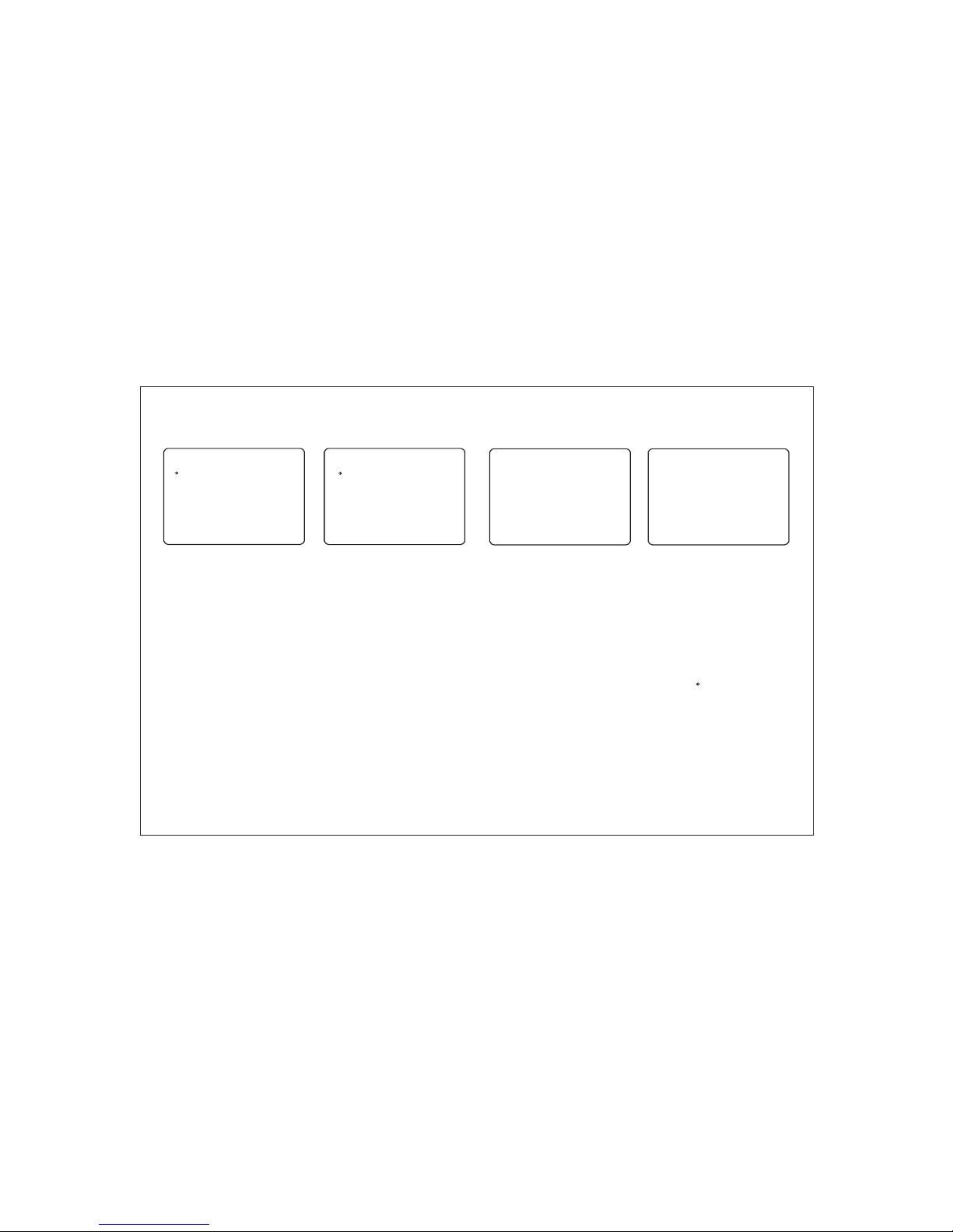
PR ESE T SE TUP
-- --- -- --- -- --- --- -- --- -- --- -
PR ESE T NO .
<E DIT S CE NE>
<C AM AD JU ST>
<E DIT L AB EL>
BA CK
EX IT
CL R PRE SE T
ED IT SC EN E - PRE SE T 001
-- --- -- --- -- --- --- -- --- -- --- -
MO VE TO S TA RT PO SI TIO N
[N EAR :S AVE / FA R:C ANC EL ]
CA M 001 O :- --00 6/0 2 X0 01 I: -- --
00 1
CA NCE L
From the dome camera setup menu, use the
joystick to highlight PRESET SETUP and key:
NEAR
PRESET NUMBER (1 - 128) - The preset
number currently being modified. If the preset
number is already defined, the speed dome
will move to that preset position, otherwise
UNDEFINED is displayed under the preset
number
<EDIT SCENE> - use this option to program
the preset position
<EDIT LABEL> - use to edit the preset label.
This option is only available when the
selected preset position is already
programmed
Highlight the item to modify and key: NEAR
Use the joystick to change the setting and key:
NEAR to save or: FAR to cancel.
<CAM ADJUST> - use to program camera
status for each preset.
CLR PRESET - use this option to delete the
current preset position
From the preset setup menu, use the joystick
to highlight EDIT SCENE and key: NEAR
Using the joystick, move the speed dome to
the desired position and zoom level and key:
NEAR to save or: FAR to cancel.
Prese t set up
Edit sc ene
10
Edit la bel
PR ESE T LA BEL S ET UP
-- --- -- --- -- --- --- -- --- -- --- -
LA B FOR P RE [ ]
-- --- -- -- 12 345 67 890
AB CDE FG HIJ
KL MNO PQ RST
UV WXY Z SA VE CA NC EL
CL EAR C AN CEL
BA CK
EX IT
From the preset setup menu, use the joystick
to highlight EDIT LABEL and key: NEAR
The solid white square shows the current
cursor position.
The flashing white square shows the currently
selected character.
Move the joystick up / down / left / right to
choose the required character and key: NEAR
to insert it in the preset label. The solid white
square moves to the next cursor position.
Repeat until the preset label is complete.
If a mistake is made, use the joystick to select
the backspace ( ) and key: NEAR. The cursor
moves back one square.
Select OK to save the preset label or
CANCEL to lose changes, and key: NEAR to
exit
Park ac tio n set up
PA RK AC TI ON SE TU P
-- --- -- --- -- --- --- -- --- -- --- -
PA RK EN AB LE
WA IT TI ME
PA RK AC TI ON
BA CK
EX IT
NO TE: P AR K TIM E UN ITS I S SEC ON DS
OF F
00 :10 :0 0
HO ME
From the motion setup menu, use the joystick
to highlight PARK ACTION SETUP and key:
NEAR
PARK ENABLE - when set to ON, the speed
dome will run the specified park action after
the wait time has elapsed
WAIT TIME - can be set between one minute
and 4 hours. If no manual control occurs
during this time, the park action will run
PARK ACTION - choose the action to run after
the wait time has elapsed. This can be return
to home position, go to a preset or run a
SCAN, GROUP or PATTERN TOUR
Highlight the item to modify and key: NEAR
Use the joystick to change the setting and key:
NEAR to save or: FAR to cancel.
Page 13
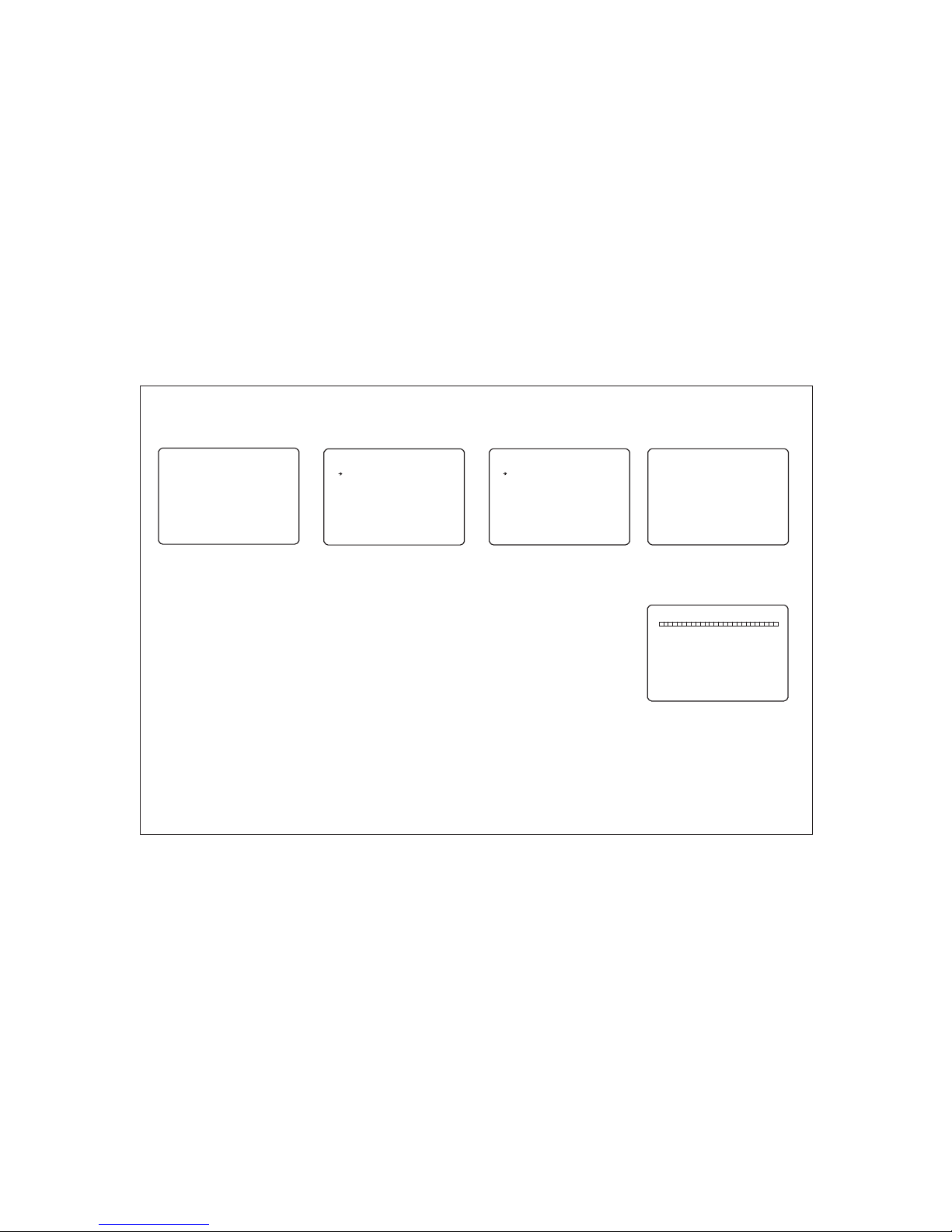
From the dome camera setup menu, use the
joystick to highlight SCAN SETUP and key:
NEAR
SCAN NO. (1-8) - shows the SCAN number
currently being modified.
1ST POS. - any defined preset between 1 &
127.
2ND POS. - any defined preset between 1
&127.
SCAN SPEED - determines the speed of
movement in degrees per second between
each preset position.
CLEAR SCAN - deletes the currently selected
VST function.
RUN SCAN - runs the currently selected
SCAN function for testing purposes
Highlight the item to modify and key: NEAR
Use the joystick to change the setting and key:
NEAR to save or: FAR to cancel.
Note: A SCAN always moves anti-clockwise to
the 1st position and then clockwise to the 2nd
position.
SCAN se tup
SC AN SE TU P
-- --- -- --- -- --- --- -- --- -- --- SC AN NO .
1S T POS .
2N D POS .
SC AN SP EE D
DI REC TI ON
CL EAR S CA N
RU N SCA N
BA CK
EX IT
1/ 8
NO NE
NO NE
30 /SE C
NO RMA L
CA NCE L
PA TTE RN S ETU P
-- --- -- --- -- --- --- -- --- -- --- -
PA TTE RN N O.
CL EAR P AT TER N
RU N PAT TE RN
<E DIT P AT TER N>
BA CK
EX IT
1/ 4
CA NCE L
From the dome camera setup menu, use the
joystick to highlight PATTERN SETUP and
key: NEAR
PATTERN NO. (1 - 4) - The pattern number
currently being modified.
CLEAR PATTERN - the currently selected
pattern can be deleted
RUN PATTERN - runs the currently selected
pattern for testing purposes
<EDIT PATTERN> - allows the operator to
program a patten tour
Highlight the item to modify and key: NEAR
Use the joystick to change the setting and key:
NEAR to save or: FAR to cancel.
Patte rn se tup
ED IT PA TT ERN 4
-- --- -- --- -- --- --- -- --- -- --- -
MO VE TO S TA RT PO SI TIO N
[N EAR :S TAR T /F AR: CAN CE L
CA M 001 O :- -00 9/0 6 X0 01 I: -- -
ED IT PA TT ERN 4
[N EAR :S AVE / FA R:D ELE TE ]
From the pattern setup menu, use the joystick
to highlight EDIT PATTERN and key: NEAR
Position the speed dome to the desired
starting point and key: NEAR
Move the dome to the various positions and
zoom levels required for the pattern. The white
squares at the top of the display show
remaining storage and disappear as the
pattern is recorded.
To save the pattern, key: NEAR
To abandon pattern programming, key: FAR
Note: Pattern tour memory is only used when
movements are recorded. Pauses between
movements, regardless of time, do not use
pattern tour memory
Edit pa tte rn
11
Camer a adj ust
CA MER A AD JUS T PR E-0 01
-- --- -- --- -- --- --- -- --- -- --- -
CA MER A AD JUS T SP ECI AL
FO CUS M OD E AUT O
CO LOU R ON
WD R -- ST ABA LI ZER - - A- SLO W SH UTT ER O FF
<W HIT E BA LAN CE >
<A E MOD E>
BA CK
EX IT
From the motion setup menu, use the joystick
to highlight CAMERA ADJUST and key:
NEAR
CAMERA ADJUST - GENERAL/SPECIAL
for each preset, specifies the camera setting.
following items are available only when
SPECIAL is selected.
Focus mode - AUTO/SEMIAUTO/MANUAL
Highlight the item to modify and key: NEAR
Use the joystick to change the setting and key:
NEAR to save or: FAR to cancel.
MANUAL - the operator must focus the
camera manually by joystick movement using
the ZOOM IN and ZOOM OUT keys.
SEMIAUTO - the camera automatically
focuses during normal PTZ movement but
preset focus information is stored when a
preset is programmed and recalled each time
the preset is called.
AUTO - the module auto focuses continually
Page 14
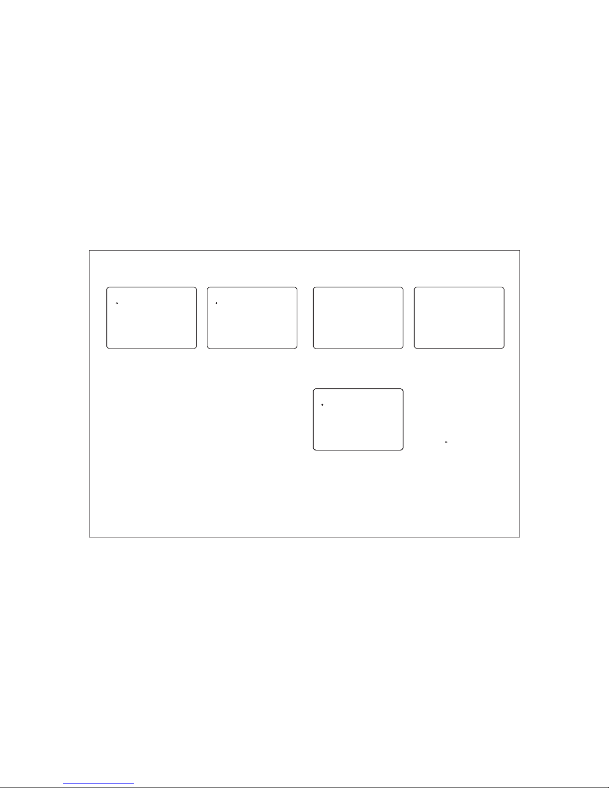
From the dome camera setup menu, use the
joystick to highlight GROUP SETUP and key:
NEAR
GROUP NO. (1-8) - shows the group number
currently being modified.
CLEAR GROUP - the currently selected group
can be deleted
RUN GROUP - runs the currently selected
group for testing purposes
<EDIT GROUP> - allows the operator to
program the group functions. operator can edit
new nesting group action in each group
Highlight the item to modify and key: NEAR
Use the joystick to change the setting and key:
NEAR to save or: FAR to cancel.
From the group setup menu, use the joystick
to highlight EDIT GROUP and key: NEAR
To edit the group, key: NEAR again
Header explanation:
NO - the item number (between 1 & 20)
ACTION - the specific action for this item
AAA - the action number (eg if ACTION is set
to PRESET, this value can be between 1 &128
DWELL - the amount of time before the next
action in the list is called
OPT - for PRESET actions, this value is the
speed at which the dome moves to the preset.
For SCAN and PATTERN, this value is the
number of times the action is repeated before
the next action is called
Move the joystick up and down to choose the
group item to modify and key: NEAR. The
ACTION is highlighted in white
Move the joystick up and down to change the
action type between NONE, PRESET, SCAN
and PATTERN.
Move the joystick left and right to select and
edit values for AAA, DWELL & OPT.
From the main menu, use the joystick to
highlight PASSWORD SETUP and key: NEAR
CHECK PASSWORD (ON/OFF) - when set to
ON, the correct password must be entered to
access the speed dome setup menus
<EDIT PASSWORD> - allows the current
password to be changed
SAVE - to save current password.
Key NEAR to save this item and continue
adding more items as necessary, or key FAR
to exit.
Group s etu p
Edit gr oup
Passw ord s etu pPassw ord s etu p
Edit gr oup
GR OUP S ET UP
-- --- -- --- -- --- --- -- --- -- --- GR OUP N O.
SA VE GR OU P
CL EAR G RO UP
RU N GRO UP
<E DIT G RO UP>
BA CK
EX IT
ED IT GR OU P 1
-- --- -- --- -- --- --- -- --- -- --- NO A CTI ON A AA DW EL L OPT
-- --- -- --- -- --- --- -- --- -- --- 1 PR ESE T 00 1 00: 03 3 60
2 NO NE
3 NO NE
4 NO NE
5 NO NE
-- --- -- --- -- --- --- -- --- -- --- BA CK
CA NCE L
PA SSW OR D SET UP
-- --- -- --- -- --- --- -- --- -- --- CH ECK P AS SWO RD O FF
<E DIT P AS SWO RD >
BA CK
EX IT
PA SSW OR D SET UP
-- --- -- --- -- --- --- -- --- -- --- CH ECK P AS SWO RD O FF
<E DIT P AS SWO RD >
SA VE CA NC EL
ED IT GR OU P 1
-- --- -- --- -- --- --- -- --- -- --- NO A CTI ON A AA DW EL L OPT
-- --- -- --- -- --- --- -- --- -- --- 1 PA TTE RN
2 PR ESE T
3 SC AN
4 PR ESE T
5 PR ESE T
-- --- -- --- -- --- --- -- --- -- --- BA CK
CA NCE L [N EAR :E DIT ]
1/ 8
CA NCE L
CA NCE L
12
1
5
3
10
4
1
36 0
8
11 0
55
00 :03
00 :08
00 :03
00 :15
01 :30
Edit Pa ssw ord
Pa ssw or d set up
-- --- -- --- -- --- --- -- --- -- --- -
From the password setup menu, use the
joystick to highlight EDIT PASSWORD and
key: NEAR
Default password is 11111111
The solid white square shows the current
cursor position.
This flashing white square shows the currently
selected character.
Move the joystick up / down / left / right to
choose the required character and key: NEAR
to insert it in the password. The solid white
square moves to the next cursor position.
Repeat until password entry is complete.
If a mistake is made, use the joystick to select
the backspace ( ) and key: NEAR. The cursor
moves back one square.
Select OK to save the password or CANCEL
to lose changes and key: NEAR to exit
Remember: When CHECK PASSWORD is set
to ON, each time the operator attempts to
enter the speed dome setup menu, the above
screen will be displayed. The correct
password must be entered to continue with
menu setup
IN PU T CUR RE NT PA SS WOR D:
11 11 111 1
Page 15
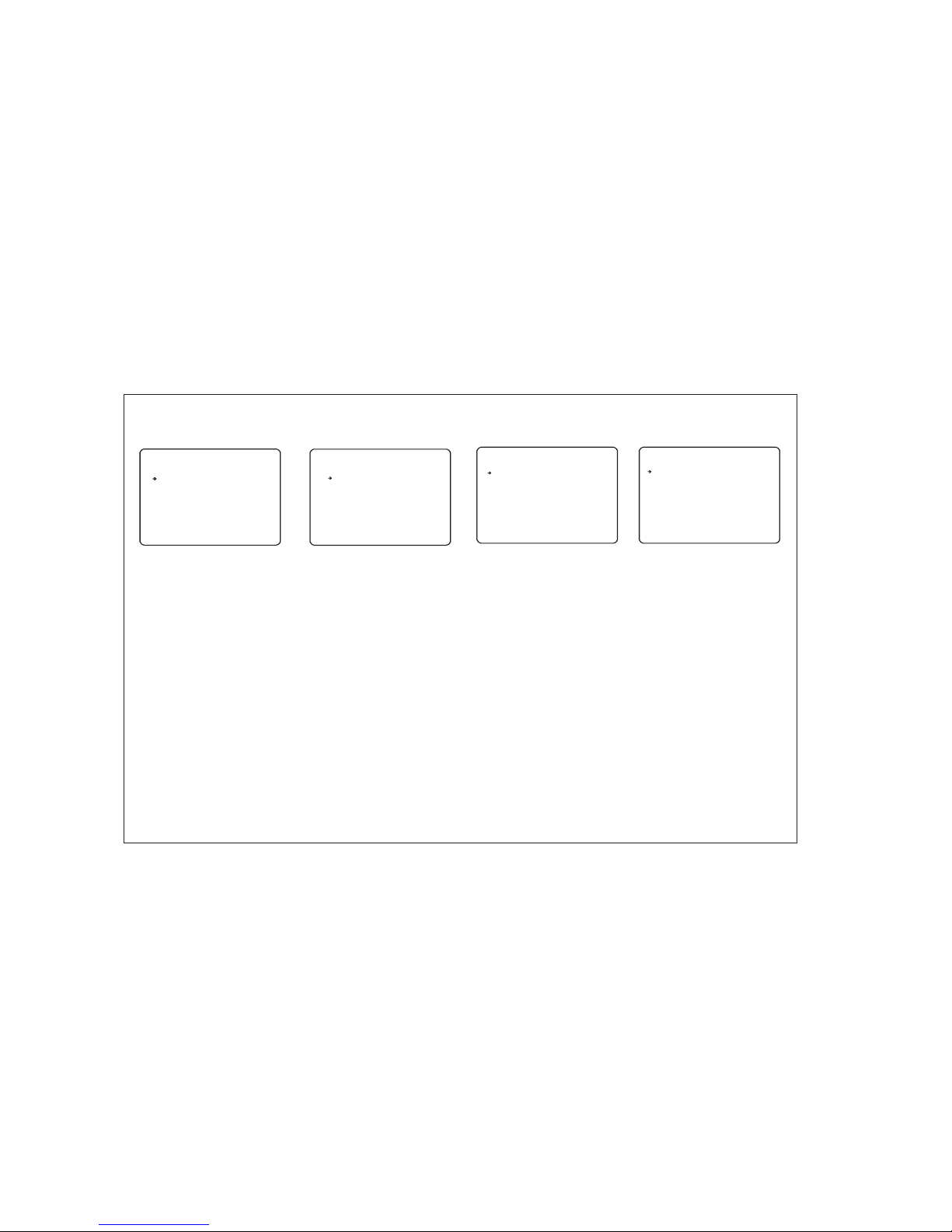
13
Sched ule S etu p
SC HED UL E SET UP
-- --- -- --- -- --- --- -- --- -- --- -
MA STE R EN ABL E
DA Y TIM E AC T NO.
1 MO N 00: 00 P AT 00 1
2 UN DEF IN ED
3 UN DEF IN ED
4
5
6
7
UN DEF IN ED
UN DEF IN ED
UN DEF IN ED
UN DEF IN ED
BA CK
From the main menu, use the joystick to
highlight SYSTEM INITIALISE and key: NEAR
DAY TIME- selecting this option to set date
and time
ACT-
Highlight the item to modify and key: NEAR
Use the joystick to change the setting to ON
and key: NEAR to run or: FAR to cancel.
selecting this option to set dome motion
OF F
OF F
AL ARM S ET UP
-- --- -- --- -- --- --- -- --- -- --- -
AL ARM I N CH ANE L 1/ 8
AL ARM E NA BLE O FF
RE LAT E PR ESE T
RE LAT E RE LAY O UT - -- IN PUT S ET UP
RE LAY A CT IVE T IM E
SA VE CA NC EL
BA CK
EX IT
From the main menu, use the joystick to
highlight ALARM SETUP and key: NEAR
ALARM IN CHANEL - selecting alarm chanel
ALARM ENABLE - this option will enable
alarm function
RELATE PRESET - selecting related preset
RELATE RELAY OUT - selecting related relay
out
I
INPUT SETUP - set up alarm input
RELAY ACTIVE TIME - set relay active time.
Highlight the item to modify and key: NEAR
Use the joystick to change the setting to ON
and key: NEAR to run or: FAR to cancel.
Syste m Ini tia lis e
SY STE M IN ITI AL ISE
-- --- -- --- -- --- --- -- --- -- --- -
CL EAR A LL D ATA
CL R DIS PL AY SE T
CL R CAM ER A SET
CL R MOT IO N SET
CL R EDI T DA TA
RE BOO T CA MER A
RE BOO T SY STE M
BA CK
EX IT
From the main menu, use the joystick to
highlight SYSTEM INITIALISE and key: NEAR
CLR EDIT DATA - this option will erase all
presets, VST functions, patterns and groups
Highlight the item to modify and key: NEAR
Use the joystick to change the setting to ON
and key: NEAR to run or: FAR to cancel.
CLEAR ALL DATA - selecting this option will
perform a full factory reset on the speed
dome. All presets, scan functions, patterns,
groups and privacy zones will be erased
CLR DISPLAY SET - this option will reset the
on screen display settings to factory default
and erase all privacy zones
CLR CAMERA SET - this option will reset the
camera module settings to factory default
CLR MOTION SET - this option will reset the
motion menu settings to factory default
Alarm S etu p
Syste m Hel p
SY STE M HE LP
-- --- -- --- -- --- --- -- --- -- --- -
IN C OMM ON U SE,
FO LLO W KE Y TO CO NT ROL M ENU :
JO G U/D /L /R TO S EL ECT
FO CUS N EA R TO CO NF IRM
FO CUS F AR T O CAN CE L
BA CK
EX IT
From the main menu, use the joystick to
highlight SYSTEM HELP and key: NEAR
Highlight the item to modify and key: NEAR
Use the joystick to change the setting to ON
and key: NEAR to run or: FAR to cancel.
Page 16

13
Using the speed dome features
Onc e the pat tern to urs, and g roups h ave bee n
pro gramm ed in the s peed do me setu p menu, t hey can a ll be
acc essed d irect ly from t he PTZ co ntrol e quipm ent by us ing the
fol lowin g seque nces.
1. To star t a patte rn tour p ress:
SHO T - 13X - ENT ER
Whe re X is a pat tern to ur numb er betw een 1 & 4
The s elect ed patt ern tou r will ru n indef inite ly unti l a manua l movem ent is ma de by the
ope rator o r an alar m input i s recei ved.
2. To star t a scan fu nctio n, pres s:
SHO T - 14X - ENT ER
Whe re X is a sca n funct ion num ber bet ween 1 & 8
The s elect ed scan f uncti on will r un inde finit ely unt il a manu al move ment is m ade by th e
ope rator o r an alar m input i s recei ved.
3. To star t a group , press :
SHO T - 15X - ENT ER
Whe re X is a gro up numb er betw een 1 & 8
The s elect ed grou p will ru n indef inite ly unti l a manua l movem ent is ma de by the o perat or or
an al arm inp ut is rec eived .
sca n funct ions
Shortcut Menu
SHO T - NO.-EN TER FUN CTION
0 (TW ICE) ENT ER MAIN M ENU
33 RE SERVED
34 RES ERVED
62 RE SERVED
63 RES ERVED
92 RES ERVED
93 RES ERVED
94 REM OTE RES ET
95 ENT ER MAIN M ENU
131 -134 CA LL PATTERN
141 -148 CA LL SCAN
151 -158 CA LL GROUP
161 -165 RE SERVED W ORD
170 W DR OFF
171 W DR ON
172 AE AUTO
173 SET SH UTTER S PEED TO 1 /120 SE C
181 LEF T POINT OF PA N LIMIT
182 RIG HT POINT O F PAN LIMI T
183 START PAN L IMIT FU NCTIO N
184 DIS ABLE PAN LI MIT FUN CTION
Page 17
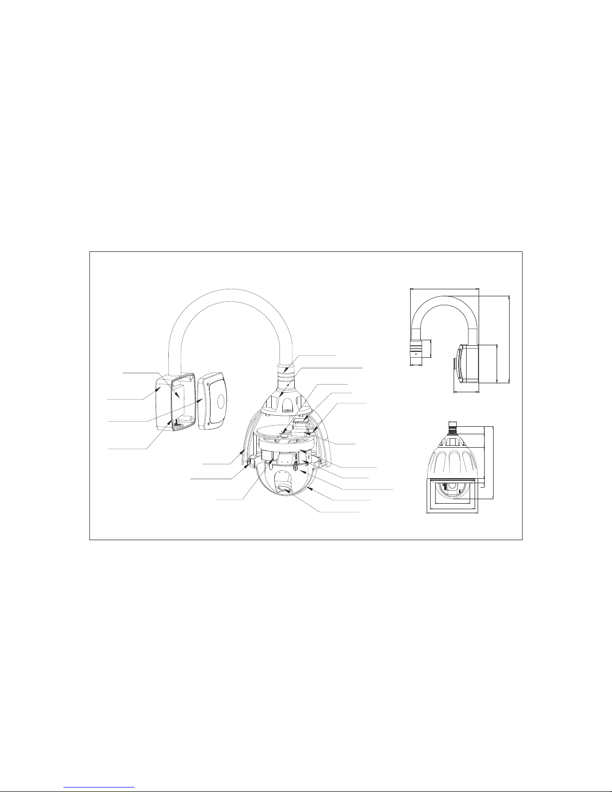
Heater
Thermostat
Fan
Thermostat
Shield Mount
Tilt Motor
Inner dome cover
Zoom Module
Dome Cover
Pan Motor
Sunshield
Dome Housing
Bracket Mount
Base
Bracket Upper
Cover
Seal
Housing Upper Cover
Bracket Joint
PCB
Parts and dimensions
42
59
138
300
248
91
230
33
3353140
19
156
325
201
14
Page 18
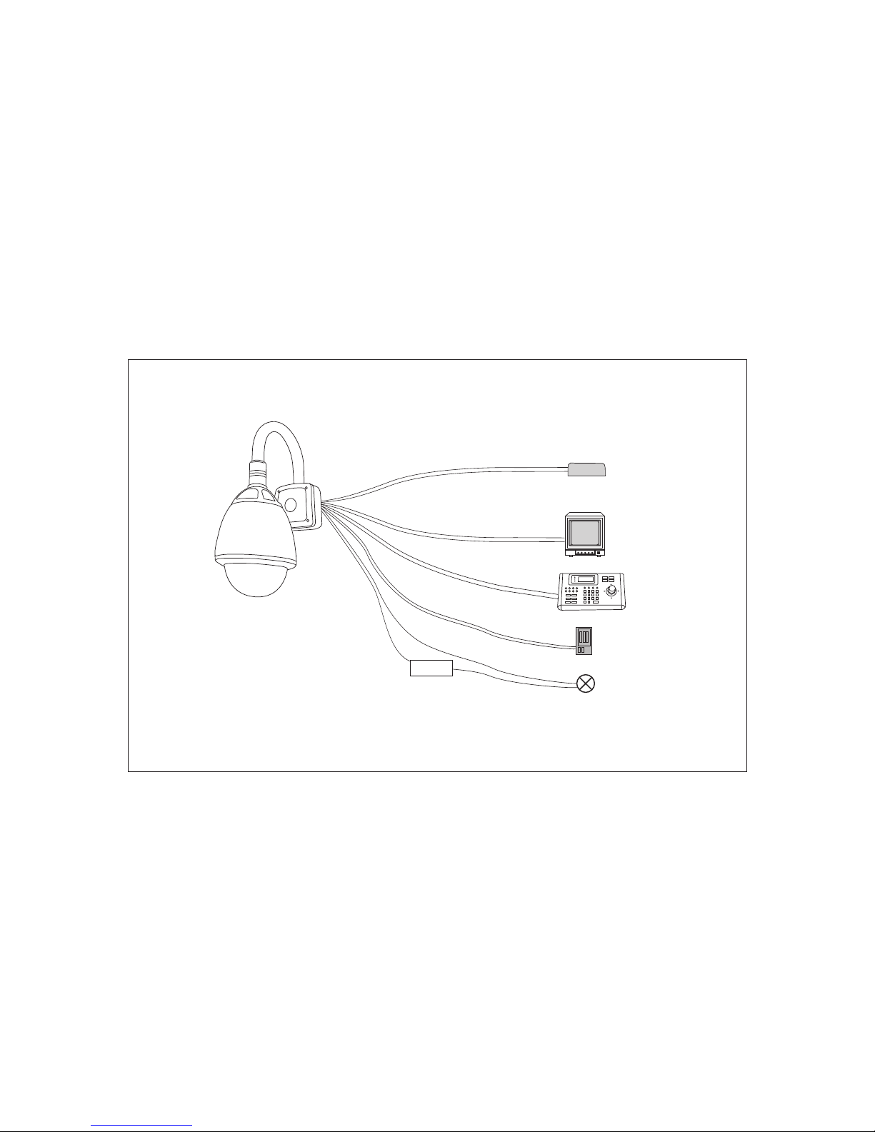
24V AC P SU
4 85
Cab le
RS-
Vid eo Ca ble
Alarm Input
Cable
Pow er Cabl e
Ala rm Sens or
Sir en / Ligh t etc.
Sir en / Ligh t etc.
pow er sour ce
Alarm Output
Cable
Wiring schematic
15
Page 19
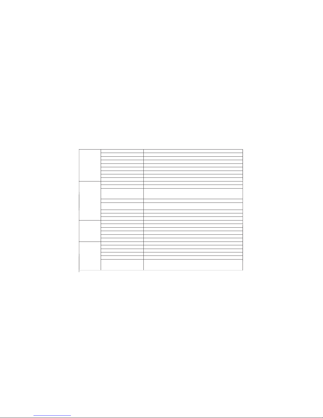
Specifications
16
Camera CCD ¼” Samsung Techwin Day / Night
Resolution 540TVL
Minimum Illumination 0.1 Lux
Optical Zoom 23x f=3.84 ~ 88.4mm, F=1.6~3.2
Digital Zoom 2X, 4X & 8X
S/N Ratio 50db
Focus Auto / Manual
White Balance ATW/ Manual
Back Light compensation Low/ Middle /High / Off
Pan / Tilt General Pan: 360 degrees continuous rotation
Tilt: 90 degrees with auto flip function
Speeds Manual / pattern tour: 1 - 255 degrees / second
Preset to preset: 360 degrees / second
VST: 1 - 255 degrees / second adjustable in 1 degree steps
Preset positions Up to 128, 10 character title per preset
Pattern tours Up to 4
VSTfunction Up to 8, speed adjustable
Groups Up to 8, each with up to 20 actions (preset, pattern tour or VST)
Privacy zones Up to 4, user definable
Park function Park to specified preset, pattern or VST after a defined period of inactivity (1 min ~ 4 hours)
Communication Data type RS-485
Protocols Pelco-D or Pelco-P
Baud rates 2400, 4800, 9600
Camera ID 1-255
Alarm I/O 8 inputs, 4 outputs
On Screen Display OSD menu, camera position, dome ID, alarm status, preset / VST/ pattern tour status
Mechanical Fan / Heater Built in
Sunshield Fitted
Operating temperature range -35 deg C to +50 deg C
Humidity <95%
Power supply 24V AC, 20 watts maximum (heater on)
Dimensions (with standard wall Overall height: 530mm
Bracket and sun shield fitted) Overall width: 230mm
Overall depth: 342mm
 Loading...