

Page 1

5-2 Factory (“Service”) Mode
Alignment and Adjustments (Electrical)
Samsung Electronics 5-1
5. Alignment and Adjustments (Electrical)
5-1 Preadjustment
5-1-1 Factory Mode
1. Do not attempt these adjustments in the Video
Mode.
2. The Factory Mode adjustments are necessary
when either the EEPROM (IC902S) or the CRT
is replaced.
3. Do not tamper with the “Adjustment” screen
of the Factory Mode menu. This screen is
intended only for factory use.
5-1-2 When EEPROM (IC902S) Is Replaced
1. When IC902S is replaced all adjustment data
revert to initial values. It is necessary to reprogram this data.
2. After IC902S is replaced, warm up the TV for
10 seconds.
5-1-3 When CRT Is Replaced
Make the following adjustments after setting up
purity and convergence:
White Balance
Sub-Brightness
Vertical Center
Vertical Size
Horizontal Size
5-2-1 Procedure for the “Adjustment” Mode
1. This mode uses the standard remote control.
The Service Mode is activated by: (1) pressing
the “FACTORY” service key on the local-keyboard, or (2) by entering the following remotecontrol sequence (within 2 seconds):
STAND-BY →DISPLAY →MENU→ MUTE→
POWER ON
2. The “SERVICE (FACTORY)” message will be
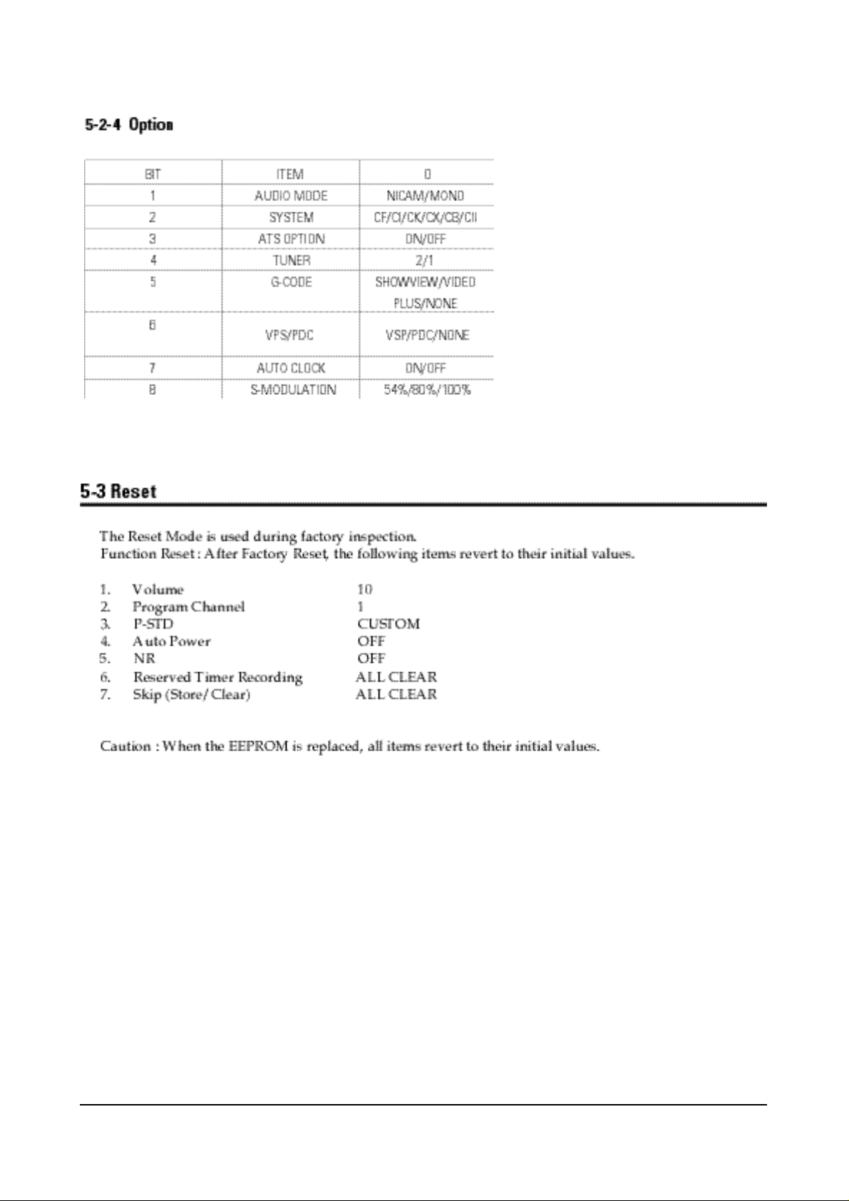
displayed. The Service Mode has three components: Adjustment, Option and Reset.
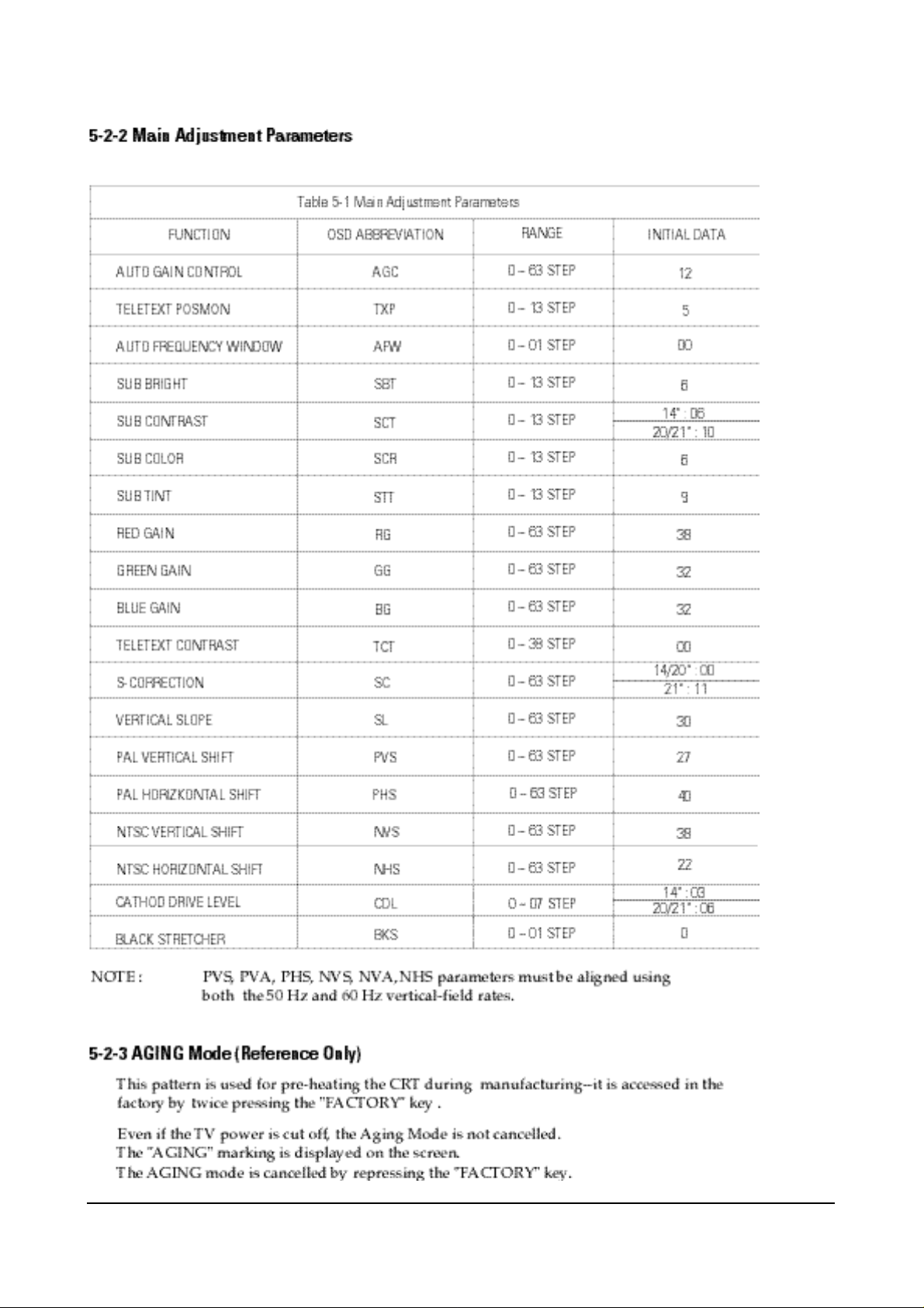
3. Access the Adjustment Mode by pressing the
“VOLUME” keys ( Up or Down). The adjustment parameters are listed in the accompanying table, and selected by pressing the CHAN-
NEL keys (s,t).
4. Selection sequences for the
PAL/SECAM B/G, L/systems:
down or up key:
AGC>TXP>AFW>SBT>SCT>SCR>STT>RG>
GG>BG>TCT>SC>SL>PVS>PHS>NVS>
NHS>CDL>BKS
5. The VOLUME keys increase or decrease the
adjustment values, (stored in the
non-volatile memory) when Adjustment Mode
is cancelled.
Page 2
Alignment and Adjustments (Electrical)
5-2 Samsung Electronics
Page 3
Alignment and Adjustments (Electrical)
Samsung Electronics 5-3
Page 4

Alignment and Adjustments (Electrical)
5-4 Samsung Electronics
5-4 Other Adjustments
5-4-1 General
1. Usually, a color TV needs only slight
touch-up adjustment upon installation.
Check the basic characteristics such as height,
horizontal and vertical sync and focus.
2. The picture should have good black and white
details. There should be no objectionable
color shading; if color shading is present,
perform the purity and convergence adjustments described below.
3. Use the specified test equipment or its
equivalent.
4. Correct impedance matching is essential.
5. Avoid overload. Excessive signal from a sweep
generator might overload the front-end of the
TV. When inserting signal markers, do not
allow the marker generator to distort test
results.
6. Connect the TV only to an AC power source
with voltage and frequency as specified on the
backcover nameplate.
7. Do not attempt to connect or disconnect any
wires while the TV is turned on. Make sure
that the power cord is disconnected before
replacing any parts.
8. To protect against shock hazard, use an
isolation transformer.
5-4-2 Automatic Degaussing
A degaussing coil is mounted around the
picture tube, so that external degaussing after
moving the TV should be unnecessary. But
the receiver must be properly degaussed upon
installation.
The degaussing coil operates for about 1
second after the power is switched ON. If the
set has been moved or turned in a different
direction, disconnect its AC power for at least
10 minutes.
If the chassis or parts of the cabinet become
magnetized, poor color purity will result. If
this happens, use an external degaussing coil.
Slowly move the degaussing coil around the
faceplate of the picture tube and the sides and
front of the receiver. Slowly withdraw the coil
to a distance of about 6 feet before removing
power.
5-4-3 High Voltage Check
CAUTION: There is no high voltage
adjustment on this chassis. The B+ power
supply must be set to +125 volts (Full color
bar input and normal picture level).
1. Connect a digital voltmeter to the second
anode of the picture tube.
2. Turn on the TV. Set the Brightness and
Contrast controls to minimum (zero beam
current).
3. The high voltage should not exceed 27.5KV.
4. Adjust the Brightness and contrast controls to
both extremes. Ensure that the high voltage
does not exceed 27.5KV under any conditions.
Page 5

Alignment and Adjustments (Electrical)
Samsung Electronics 5-5
5-4-4 FOCUS Adjustment
1. Input a black and white signal.
2. Adjust the tuning control for the clearest picture.
3. Adjust the FOCUS control for well defined scanning lines in the center area of the screen.
5-4-5 Screen Adjustment
1. Turn to the ACTIVE channel.
2. Adjust the VR screen for a normal picture is (no blooming or flyback line).
3. Adjust the FOCUS control for well defined scanning lines in the center area of the screen.
5-4-6 Purity Adjustment
1. Warm up the receiver for at least 20 minutes.
2. Plug in the CRT deflection yoke and tighten the clamp screw.
3. Plug the convergence yoke into the CRT and set in as shown in Fig. 5-1.
4. Input a black and white signal.
5. Fully demagnetize the receive by applying an external degaussing coil.
6. Turn the CONTRAST and BRIGHTNESS controls to maximum.
7. Loosen the clamp screw holding the yoke. Slide the yoke backward or forward to provide
vertical green belt. (Fig. 5-2).
8. Tighten the convergence yoke.
9. Slowly move the deflection yoke forward, and adjust for the best overall green screen.
10. Temporarily tighten the deflection yoke.
11. Produce blue and red rasters by adjusting the low-light controls. Check for good purity
in each field.
12. Tighten the deflection yoke.
Page 6

Alignment and Adjustments (Electrical)
5-6 Samsung Electronics
5-4-7 White Balance Adjustment
5-4-7 (A) HIGH-LIGHT ADJUSTMENT
1. Input either a Lion Head or a “pure white” pattern.
2. Warm up the TV for 30 minutes.
3. Check the data in the Service Mode
4. Adjust RG, BG in the Factory Mode.
5-4-7 (B) LOW-LIGHT ADJUSTMENT
1. Automatically accomplished during the high-light adjustment.
Fig. 5 -1 Convergence Magnet Assembly
Fig. 5-2 Center Convergence Adjustment
Page 7

Alignment and Adjustments (Electrical)
Samsung Electronics 5-7
5-4-8 Center Convergence Adjustment
1. Warm up the receiver for at least 20 minutes.
2. Adjust the two tabs of the 4 pole magnets to
change the angle between them. Superimpose
the red and blue vertical lines in the center
area of the screen.
3. Adjust the Brightness and Contrast controls for
a well defined picture.
4. Adjust the two-tab pairs of the 4 pole magnets,
and change the angle between them.
Superimpose the red and the blue vertical
lines in the center area of the screen.
5. Turn the both tabs at the same time, keeping
the angle constant, and superimpose the red
and blue horizontal line in the center of the
screen.
6. Adjust the two-tab pairs of the 6-pole magnets
to superimpose the red and blue line onto the
green. (Changing the angle affects the vertical
lines, and rotating both magnets affects the
horizontal lines.)
7. Repeat adjustments 2~6, if necessary.
8. Since the 4-pole magnets and 6-pole magnets
interact, the dot movement is complex
(Fig. 5-3).
Fig 5-3 Center Convergence Adjustment
5-4-9 Dual Tuner AFT Adjustment
Page 8

Alignment and Adjustments (Electrical)
5-8 Samsung Electronics
5-5 Electrical Adjustment (VCR Section)
5-5-1 Preparation
Electrical adjustments are required after replacing
circuit components and certain mechanical parts.
It is important to perform these adjustment only
after all repairs and replacements have been com
pleted. Also, do not attempt these adjustments
unless the proper equipment is available.
5-5-2 Required Test Equipment
1. Color Television or Monitor
2. Oscilloscope : Wide-band, dual-trace, triggered delayed sweep.
3. DC Voltmeter
4. TV CH Generator
5. Attenuator
6. Recording tape. (Blank tape)
7. Pattern Generator : PAL color bar. 100%
White.
Fig. 5-4 Alignment Tape
Fig. 5-5 Color bar signal of pattern generator
Fig. 5-6 Color bar signal of alignment tape (75% Color Bars)
Page 9

Alignment and Adjustments (Electrical)
Samsung Electronics 5-9
A
0
0
0
1
1
0
0
0
1
0
B
0
0
0
0 ->1
1
1
0
0
0
1
C
0
0
0
1
0
0
1
1
0
1
S
0
1
1
1
X
X
1
X
X
X
F
0
X
X
X
X
X
X
X
X
X
Eject
Unload POWER OFF
(Tape loading start point)
(Tape loading end point)
Reverse Picture Ssarch, Reverse SLOW
Play, Rec,F-PS,Still,SLOW,F-ADV
Stop (Play position 5 Min. over)
(MAIN Break ON MODE)
High speed Rew, Low speed FF
High speed FF, Low speed Rew
STANBY
POWER OFF
LOADING START
LOADING END
REV
PLAY
STOP1
STOP 2
FF / REW 1
FF / REW 2
5-5-3 PROGRAM SW
POSITION
PROGRAM S/W TAPE SEN
OPERATION MODE
X : DON’T CARE
Page 10

Alignment and Adjustments (Electrical)
5-10 Samsung Electronics
5-5-4 TWIN PAL OPTION TABLE
Page 11

Alignment and Adjustments (Electrical)
Samsung Electronics 5-11
5-5-5 WITHOUT KEY PART LIST
Page 12

Alignment and Adjustments (Electrical)
5-12 Samsung Electronics
5-5-6 HI-FI AUDIO BLOCK PART LIST
Page 13

Alignment and Adjustments (Electrical)
Samsung Electronics 5-13
Page 14

Alignment and Adjustments (Electrical)
5-14 Samsung Electronics
5-5-7 WITHOUT SECAM PART LIST
Page 15

Alignment and Adjustments (Electrical)
Samsung Electronics 5-15
 Loading...