

Page 1

SyncMaster NC190, NC240
LCD Monitor
User Manual
The color and the appearance may differ depending on the
product, and the specifications are subject to change
without prior notice to improve the performance.
Page 2

Table Of Contents
MAJOR SAFETY PRECAUTIONS
Before You Start . . . . . . . . . . . . . . . . . . . . . . . . . . . . . . . . . . . . . . . . . . . 1-1
Care and Maintenance . . . . . . . . . . . . . . . . . . . . . . . . . . . . . . . . . . . . . . 1-2
Safety Precautions . . . . . . . . . . . . . . . . . . . . . . . . . . . . . . . . . . . . . . . . . 1-3
INSTALLING THE PRODUCT
Package Contents . . . . . . . . . . . . . . . . . . . . . . . . . . . . . . . . . . . . . . . . . 2-1
Installing the Stand . . . . . . . . . . . . . . . . . . . . . . . . . . . . . . . . . . . . . . . . 2-2
Installing a Wall Mount . . . . . . . . . . . . . . . . . . . . . . . . . . . . . . . . . . . . . . 2-3
Connecting to your Network . . . . . . . . . . . . . . . . . . . . . . . . . . . . . . . . . 2-4
Connecting Power . . . . . . . . . . . . . . . . . . . . . . . . . . . . . . . . . . . . . . . . . 2-5
Connecting to another Monitor . . . . . . . . . . . . . . . . . . . . . . . . . . . . . . . 2-6
Connecting with a PC . . . . . . . . . . . . . . . . . . . . . . . . . . . . . . . . . . . . . . . 2-7
Connecting a Stereo Cable . . . . . . . . . . . . . . . . . . . . . . . . . . . . . . . . . . 2-8
Connecting USB . . . . . . . . . . . . . . . . . . . . . . . . . . . . . . . . . . . . . . . . . . . 2-9
Connecting Headphones . . . . . . . . . . . . . . . . . . . . . . . . . . . . . . . . . . . 2-10
Connecting MIC . . . . . . . . . . . . . . . . . . . . . . . . . . . . . . . . . . . . . . . . . . 2-11
Kensington Lock . . . . . . . . . . . . . . . . . . . . . . . . . . . . . . . . . . . . . . . . . 2-12
USING THE PRODUCT
What is a PC over IP? . . . . . . . . . . . . . . . . . . . . . . . . . . . . . . . . . . . . . . . 3-1
Connect to the host PC using a LAN cable . . . . . . . . . . . . . . . . . . . . . 3-2
Plug & Play . . . . . . . . . . . . . . . . . . . . . . . . . . . . . . . . . . . . . . . . . . . . . . . 3-3
Standard Signal Mode Table . . . . . . . . . . . . . . . . . . . . . . . . . . . . . . . . . 3-4
Installing the Device Driver . . . . . . . . . . . . . . . . . . . . . . . . . . . . . . . . . . 3-5
Product Operating Buttons . . . . . . . . . . . . . . . . . . . . . . . . . . . . . . . . . . 3-6
Using the Screen Adjustment Menu (OSD: On Screen Display) . . . . 3-7
INSTALLING THE SOFTWARE
PCoIP . . . . . . . . . . . . . . . . . . . . . . . . . . . . . . . . . . . . . . . . . . . . . . . . . . . . 4-1
Natural Color . . . . . . . . . . . . . . . . . . . . . . . . . . . . . . . . . . . . . . . . . . . . . . 4-2
MagicTune . . . . . . . . . . . . . . . . . . . . . . . . . . . . . . . . . . . . . . . . . . . . . . . . 4-3
MultiScreen . . . . . . . . . . . . . . . . . . . . . . . . . . . . . . . . . . . . . . . . . . . . . . . 4-4
TROUBLESHOOTING
Monitor Self-Diagnosis . . . . . . . . . . . . . . . . . . . . . . . . . . . . . . . . . . . . . 5-1
Before Requesting Service . . . . . . . . . . . . . . . . . . . . . . . . . . . . . . . . . . 5-2
FAQ . . . . . . . . . . . . . . . . . . . . . . . . . . . . . . . . . . . . . . . . . . . . . . . . . . . . . 5-3
MORE INFORMATION
Specifications . . . . . . . . . . . . . . . . . . . . . . . . . . . . . . . . . . . . . . . . . . . . . 6-1
Power Saving Function . . . . . . . . . . . . . . . . . . . . . . . . . . . . . . . . . . . . . 6-2
Contact SAMSUNG WORLDWIDE . . . . . . . . . . . . . . . . . . . . . . . . . . . . . 6-3
Correct Disposal of This Product
(Waste Electrical & Electronic Equipment) . . . . . . . . . . . . . . . . . . 6-4
Page 3
Major Safety Precautions 1-1
1 Major Safety Precautions
1-1 Before You Start
Icons used in this manual
Using this Manual
• Make yourself fully aware of the safety precautions before using this product.
• If a problem occurs, refer to the 'Troubleshooting' section.
Copyright Notice
The contents of this manual are subject to change without prior notice for performance improvement.
Copyright © 2009 Samsung Electronics Co., Ltd. All Rights Reserved.
The copyright of this manual is reserved by Samsung Electronics, Co., Ltd.
The contents of this manual may not be partially or in whole reproduced, distributed or used in any form without the written
permission of Samsung Electronics, Co., Ltd.
The SAMSUNG logo and SyncMaster are the registered trademarks of Samsung Electronics, Co., Ltd.
Microsoft, Windows and Windows NT are the registered trademarks of Microsoft Corporation.
VESA, DPM and DDC are the registered trademarks of the Video Electronics Standard Association.
The ENERGY STAR
®
logo is the registered trademark of the U.S. Environmental Protection Agency.
All other trademarks mentioned herein belong to their respective companies.
ICON NAME MEANING
Caution Indicates cases where the function may not work or the setting may be canceled.
Note Indicates a hint or tip to operate a function.
An administration fee may be charged if either
(a) an engineer is called out at your request and there is no defect in the product
(i.e. where you have failed to read this user manual).
(b) you bring the unit to a repair centre and there is no defect in the product
(i.e. where you have failed to read this user manual).
The amount of such administration charge will be advised to you before any work or home visit is carried
out.
Page 4

1-2 Major Safety Precautions
1-2 Care and Maintenance
External Surface and Screen Maintenance
About persistent images
• Displaying a still image for a long time may create a persistent image or stain on the screen. If you do not use the product for
a long time, set the power-saving mode or screen saver.
• Due to technological constraints of the LCD Panel manufacturer, the images generated by this product may appear either
brighter or darker than normal by appr. 1ppm (parts per million) pixel.
The number of sub-pixels of an LCD panel by size: The number of Sub-Pixels = Max. Horizontal Resolution x Max. Vertical
Resolution x 3
Example) If the maximum resolution is 1280 x 1024 (1920 x 1080), the number of sub-pixels is 1280 x 1024 (1920 x 1080) x 3
=3,932,160 (6,220,800).
Clean the product with a soft, damp cloth.
• Do not clean the product with an inflammable substance such
as benzene or thinner or with a wet cloth. This may result in a
problem with the product.
• Do not scratch the screen with your fingernails or a sharp
object.
This may result in scratches or damage to the product.
• Do not clean the product directly by spraying water onto the
product.
If water enters the product, it may result in fire, electric shock or
a problem with the product.
• A white stain may be generated on the surface of the highglossy model due to the inherent characteristics of the material,
if a supersonic humidifier is used.
The appearance and the color may differ depending on the
model.
Page 5
Major Safety Precautions 1-3
1-3 Safety Precautions
Icons used for safety precautions
Meaning of Signs
Power Related
The following images are for your reference and may differ depending on models and countries.
Warning
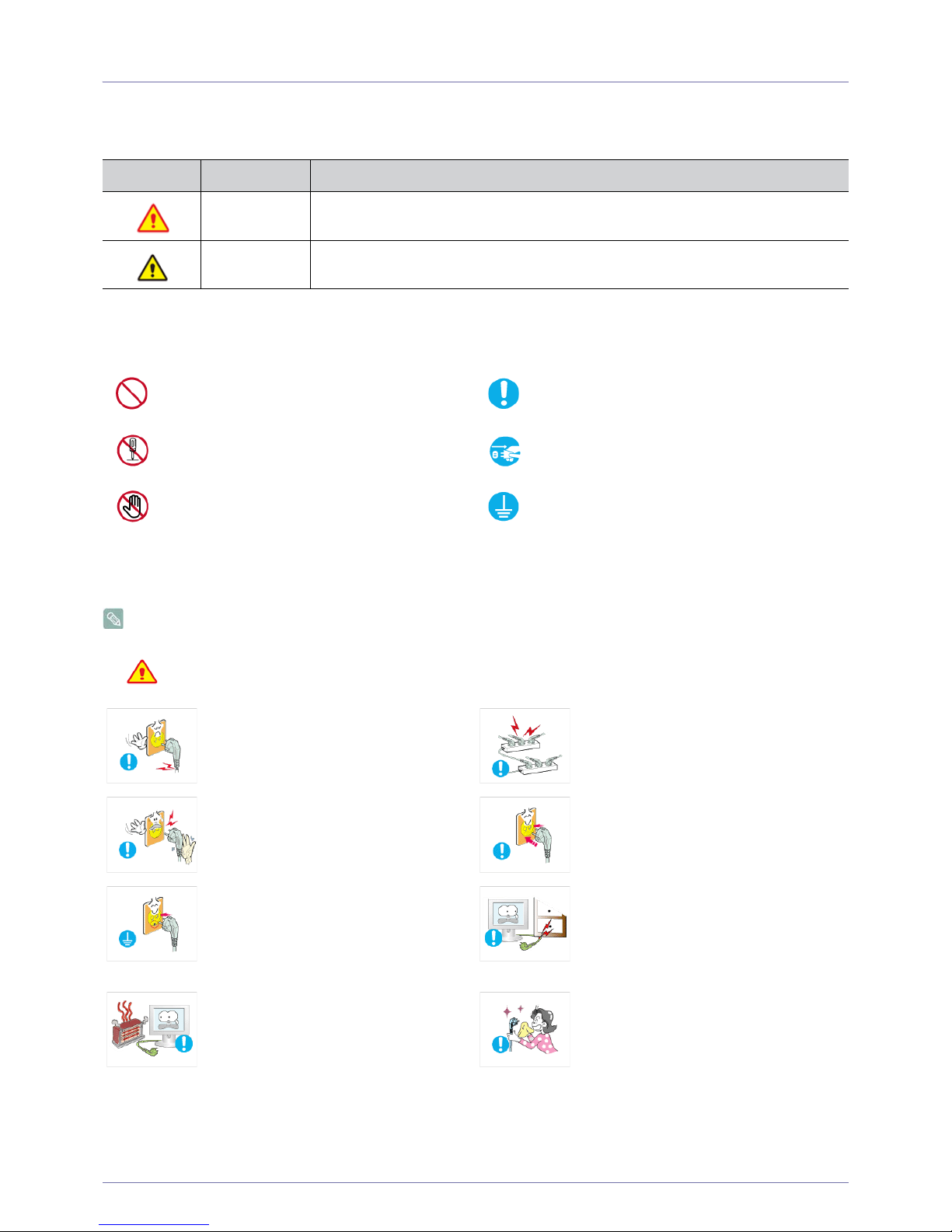
ICON NAME MEANING
Warning
Failing to follow the precautions marked with this sign, may result in a serious injury or
even a fatality.
Caution
Failing to follow the precautions marked with this sign, may result in a personal injury or
property damage.
Do not perform. Must be followed.
Do not disassemble.
The power plug must be unplugged from the
wall outlet.
Do not touch. Must be grounded to prevent electric shock.
Avoid using a damaged power cord or plug or a
loose power outlet.
• Otherwise, it may result in electric shock or
fire.
Avoid connecting multiple electric appliances to
a single wall outlet.
• Otherwise, it may result in fire due to
overheating of the wall outlet.
Avoid plugging in or unplugging the power
supply with wet hands.
• Otherwise, it may result in electric shock.
Plug the power plug in firmly.
• Otherwise, it may result in fire.
Make sure to connect the power cord to a
grounded wall outlet (for insulation class 1
equipment only).
• Otherwise, it may result in electric shock or
injury.
Avoid bending or twisting the power cord
excessively and avoid placing heavy objects on
the cord.
• Otherwise, it may result in electric shock or
fire due to a damaged power cord.
Keep the power cord and the product away
from a heater.
• Otherwise, it may result in electric shock or
fire.
If the pins of the power plug or the wall outlet
are covered in dust, clean it using a dry cloth.
• Otherwise, it may result in fire.
Page 6
1-3 Major Safety Precautions
Caution
Installation Related
Warning
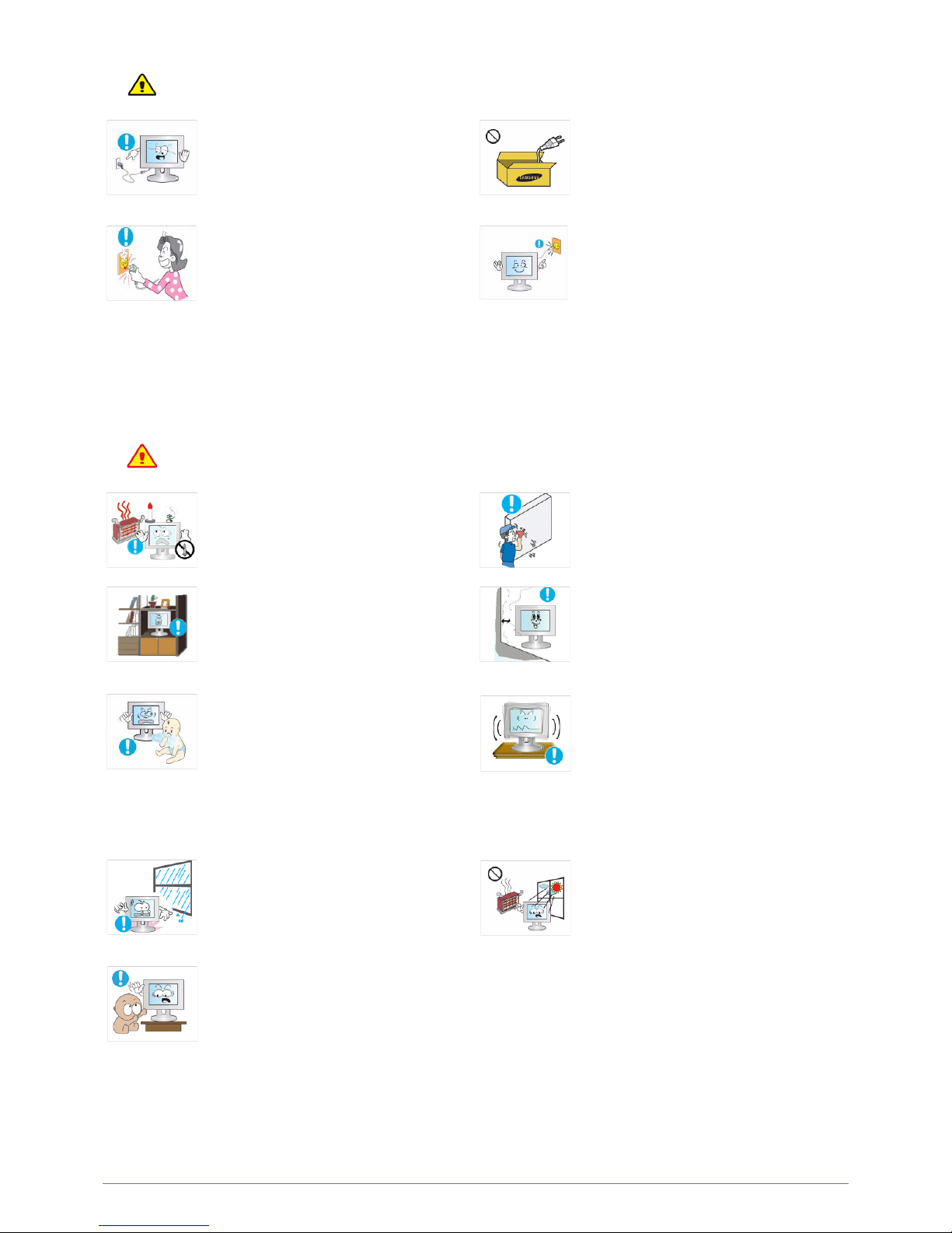
Avoid unplugging the power plug while the
product is operating.
• Otherwise, it may damage the product due
to electric shock.
Make sure to use only the power cord supplied
by Samsung. In addition, do not use the power
cord of another electric appliance.
• Otherwise, it may result in electric shock or
fire.
When unplugging the power plug from the wall
outlet, make sure to hold it by the plug and not
by the cord.
• Otherwise, it may result in electric shock or
fire.
Connect the power plug to a wall outlet that can
be easily reached.
• When a problem occurs with the product,
you must unplug the power plug to cut the
power off completely. You cannot cut the
power off completely using only the power
button on the product.
Avoid placing burning candles, mosquitorepellent or cigarettes on the product and
installing the product near a heater.
• Otherwise, it may result in fire.
Ask an installation engineer or relevant
company to install the product onto a wall.
• Otherwise, it may result in injury.
• Make sure to use the specified wall mount.
Avoid installing the product in a badly-ventilated
location such as inside a bookshelf or closet.
• Otherwise, it may result in fire due to
internal over-heating.
Keep a distance of at least 4 inches (10 cm )
from the wall when installing the product for
ventilation.
• Otherwise, it may result in fire due to
internal over-heating.
Keep the plastic bags used to pack the product
away from children.
• If children place the plastic bags over their
heads, they may suffocate.
Avoid installing the product in a location that is
unstable or exposed to excessive vibrations
such as on an unstable or slanted shelf.
• The product may fall and this may result in
damage to the product or injury.
• If you use the product in a location exposed
to excessive vibrations, it may result in a
problem with the product or fire.
Avoid installing the product in a location
exposed to dust, moisture (sauna), oil, smoke
or water (rain drops) and installing it within a
vehicle.
• This may result in electric shock or fire.
Avoid installing the product in a location
exposed to direct sunlight or heat source such
as a fire or heater.
• This may shorten the product life cycle or
cause fire.
Avoid installing the product at a height where
children may reach it.
• If a child touches the product, the product
may fall and this may result in injury.
• Since the front part is heavier, install the
product on a flat and stable surface.
Page 7
Major Safety Precautions 1-3
Caution
Cleaning Related
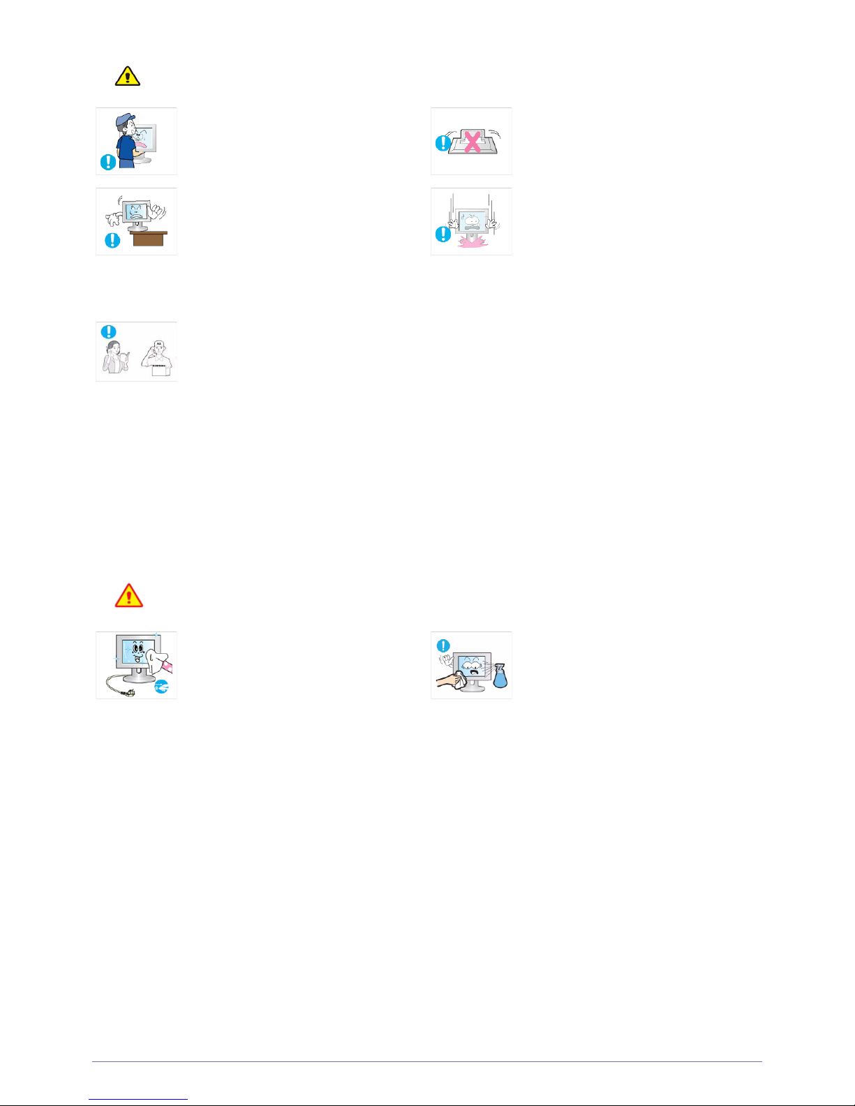
Do not let the product drop while moving it.
• This may result in a problem with the
product or injury.
Do not place the product face down on the
floor.
• This may damage the panel of the product.
When installing the product on a console or
shelf, make sure that the front of the product
does not protrude out of the console or shelf.
• Otherwise, this may cause the product to
fall off and result in a malfunction or injury.
• Make sure to use a cabinet or shelf suitable
to the size of the product.
When putting the product down, handle it
gently.
• Otherwise, it may result in a problem with
the product or injury.
If the product is installed in a location where the
operating conditions vary considerably, a
serious quality problem may occur due to the
surrounding environment. In this case, install
the product only after consulting one of our
service engineers about the matter.
• Places exposed to microscopic dust,
chemicals, too high or low temperature,
high humidity, such as airports or stations
where the product is continuously used for
a long time and so on.
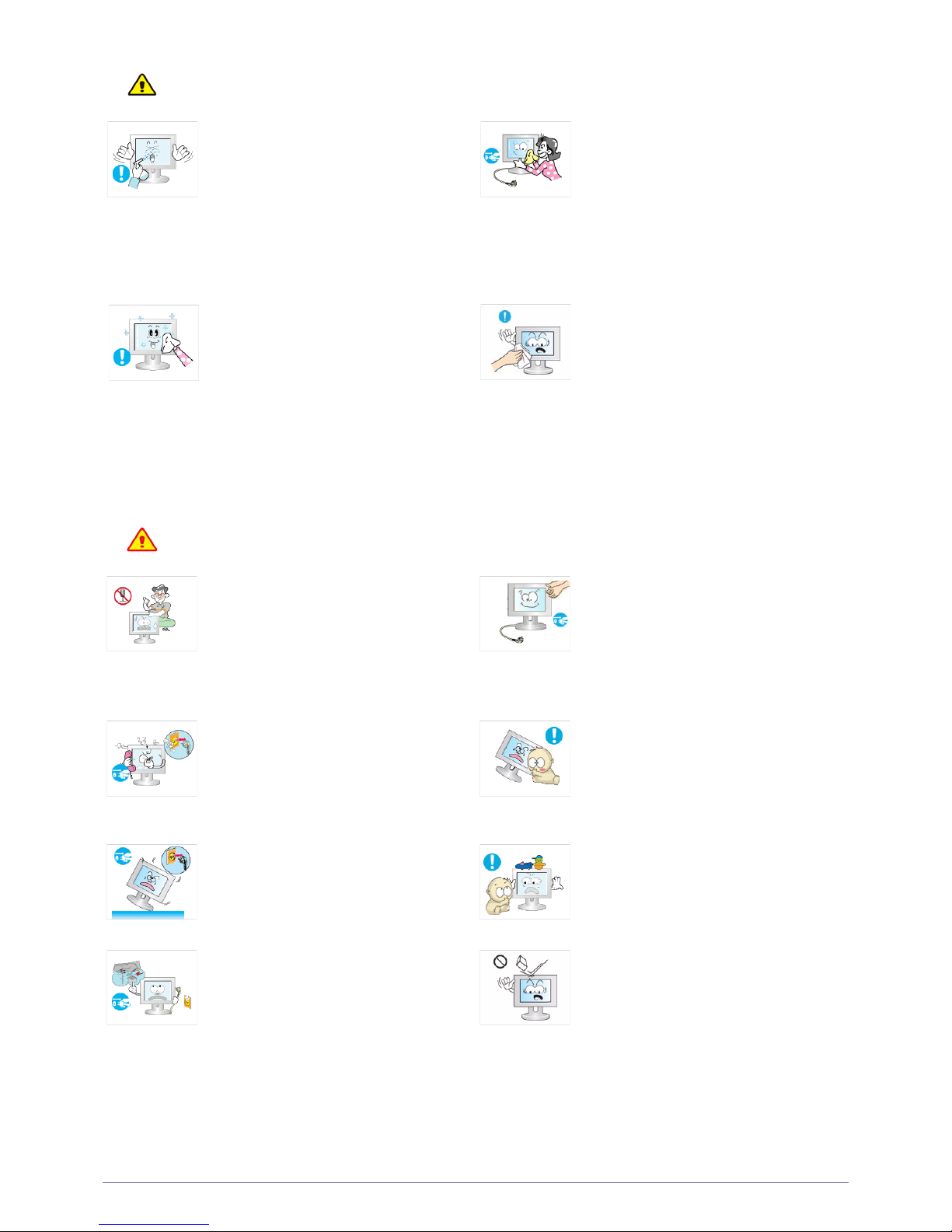
Since using a surfactant, which contains a large amount of alcohol, solvent or other strong chemicals, may result
in the discoloration or cracking of the product exterior or the panel surface coming off, be sure to use water only.
Before cleaning the product, unplug the power
cord.
• Otherwise, it may result in electric shock or
fire.
When cleaning the product, do not spray water
directly over the product parts.
• Make sure that water does not enter the
product.
• Otherwise, it may result in fire, electric
shock or a problem with the product.
Page 8
1-3 Major Safety Precautions
Caution
Usage Related
Warning
Avoid spraying cleansing agent directly onto
the product.
• This may result in discoloration or cracking
of the exterior of the product or the panel
coming off.
When cleaning the product, disconnect the
power cord and clean the product with
a soft,
damp cloth.
• Avoid using chemicals such as wax,
benzene, alcohol, thinner, mosquito-
repellent, fragrance or lubricants when
cleaning the product.
This may result in the exterior being
deformed or the print being removed.
• Use a soft, damp cloth with water and wipe
the product with it
Since the exterior of the product is easily
scratched, be sure to use a proper cleansing
cloth. Use the cleansing cloth with a small
amount of water. However, if the cloth is
contaminated by alien substances, it may result
in scratches to the exterior; therefore shake off
any alien substances from the cloth before
using it.
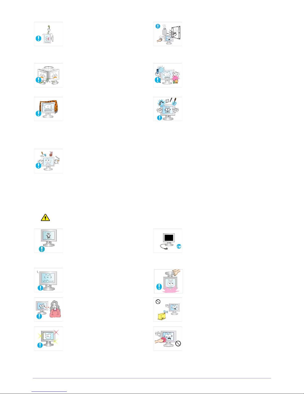
Since a high voltage runs through the product,
never disassemble, repair or modify the product
yourself.
• Otherwise, it may result in fire or electric
shock.
• If the product needs to be fixed, contact
a service center.
When cleaning the product, do not spray water
directly over the product parts.
• Make sure that water does not enter the
product.
• Otherwise, it may result in fire, electric
shock or a problem with the product.
If the product generates a strange noise, a
burning smell, or smoke, unplug the power
plug immediately and contact a service center.
• Otherwise, it may result in electric shock or
fire.
Avoid letting children to hang or climb onto the
product.
• Otherwise, it may result in the product
falling and this may result in injury or death.
If you drop the product or the case is damaged, turn the power off and unplug the
power cord. Contact a service center.
• Otherwise, it may result in fire or electric
shock.
Avoid placing objects such as toys and cookies
on top of the product.
• If a child hangs over the product to grab an
object, the object or the product may fall
and this may result in injury or even death.
When thunder or lighting occurs, unplug the
power cord and under no circumstance touch
the antenna cable as this is dangerous.
• Otherwise, it may result in electric shock or
fire.
Avoid dropping an object over the product or
cause impact to the product.
• Otherwise, it may result in electric shock or
fire.
Page 9
Major Safety Precautions 1-3
Caution
Avoid moving the product by pulling the power
cord or antenna cable.
• Otherwise, it may result in electric shock,
fire or a problem with the product due to
damage to the cable.
When a gas leak occurs, do not touch the
product or the power plug and ventilate
immediately.
• A spark may result in an explosion or fire.
• During a thunder or lighting storm, do not
touch the power cord or antenna cable.
Avoid lifting up or move the product by holding
only the power cord or signal cable.
• Otherwise, it may result in electric shock,
fire or a problem with the product due to
damage to the cable.
Avoid using or placing inflammable spray or
objects near the product.
• This may result in an explosion or fire.
Take care not to block the vent by a table cloth
or curtain.
• Otherwise, it may result in fire due to
internal overheating.
Avoid inserting metal objects such as a
chopsticks, coins or hairpins, or inflammable
objects into the product (the vents, ports, etc).
• If water or an alien substance enters the
product, turn the power off, unplug the
power cord and contact a service center.
• Otherwise, it may result in a problem with
the product, electric shock or fire.
Avoid placing a liquid container such as a vase,
flowerpot, beverage, cosmetics or drugs, or a
metal object over the product.
• If water or an alien substance enters the
product, turn the power off, unplug the
power cord and contact a service
center.
• Otherwise, it may result in a problem with
the product, electric shock or fire.
Displaying a still image for a long time may
create a persistent image or stain on the
screen.
• If you do not use the product for a long time,
use the power-saving mode or set the
screensaver to the moving picture mode.
When not using the product for a long time
such as leaving your home, unplug the power
cord from the wall outlet.
• Otherwise, it may cause dust accumulation
and result in fire caused by overheating or
short circuit or result in an electric shock.
Set the appropriate resolution and frequency
for the product.
• Otherwise, it may result in eye strain.
Avoid turning the product upside down or move
the product holding only the stand.
• This may cause the product to fall resulting
in damage to the product or injury.
Watching the product from too close a distance
continuously may damage your eyesight.
Avoid using a humidifier or cooker near the
product.
• Otherwise, it may result in electric shock or
fire.
It is important to give your eyes some rest (5
minutes every hour) when viewing the product
screen for long periods of time.
• This will alleviate any eye strain.
Since the display panel is hot after using it for a
long time, do not touch the product.
Page 10
1-3 Major Safety Precautions
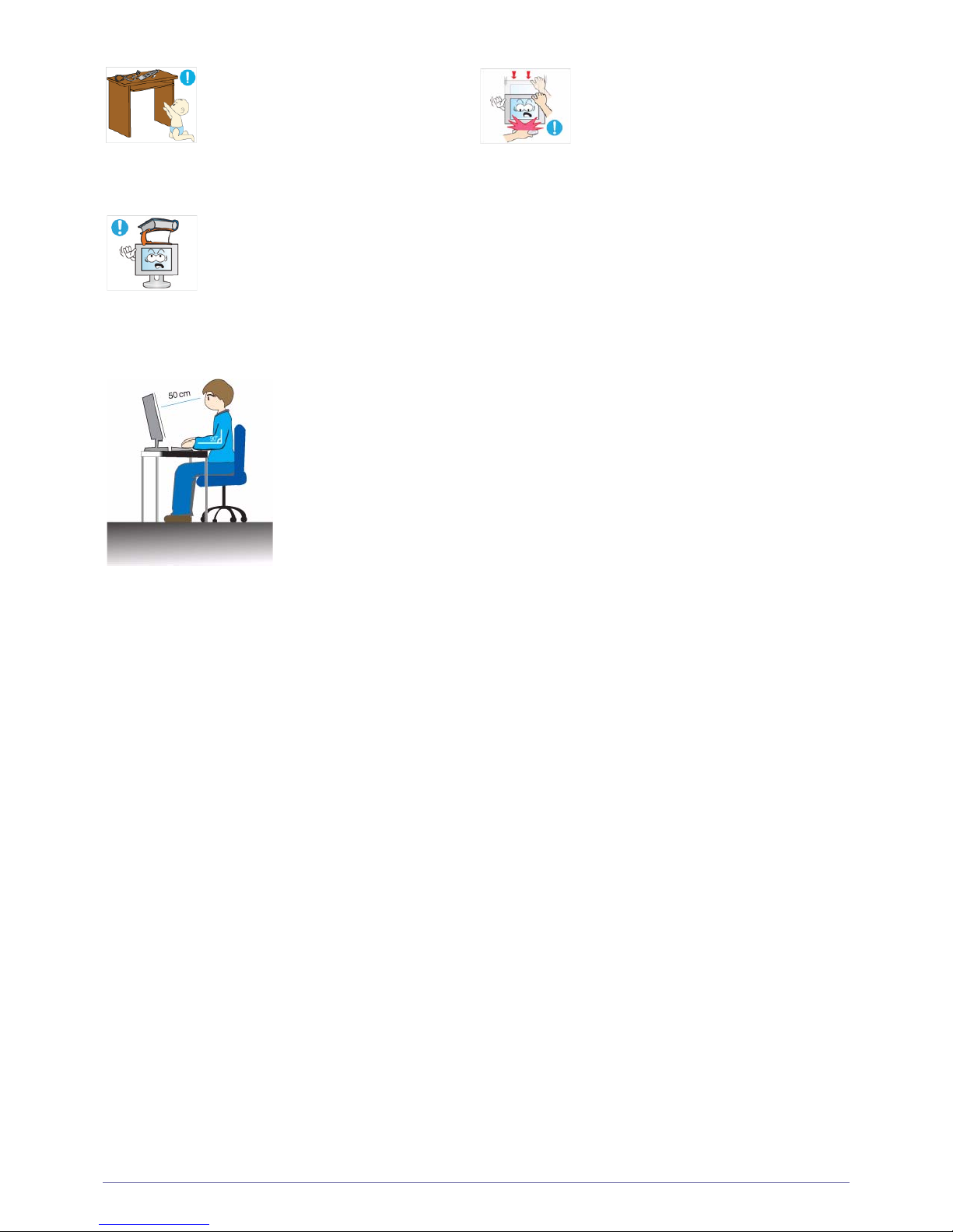
Maintaining the Correct Posture when Using this Product
Keep small accessories away from the children. Take care when adjusting the angle of the
product or the height of the stand.
• If your hand or finger is caught, you may be
injured.
• If the product is tilted excessively, the
product may fall and this may result in
injury.
Avoid placing a heavy object over the product.
• Otherwise, it may result in a problem with
the product or injury.
Maintain the correct posture when using this product.
• Straighten your back.
• Keep a distance of 45~50 cm(18~ 20inches) from your eyes to the screen. Look down at
the screen and face the screen forwards.
• Maintain the correct posture when using this product.
• Adjust the angle of the product so that light is not reflected onto the screen.
• Keep your elbow at a right angle and keep your arm level with the back of your hand.
• Keep your elbow at a right angle.
• Place your heels flat on the ground while keeping your knees at an angle of 90 degrees or
higher and maintain the position of your arm so that your arm is below your heart.
Page 11
Installing the Product 2-1
2 Installing the Product
2-1 Package Contents
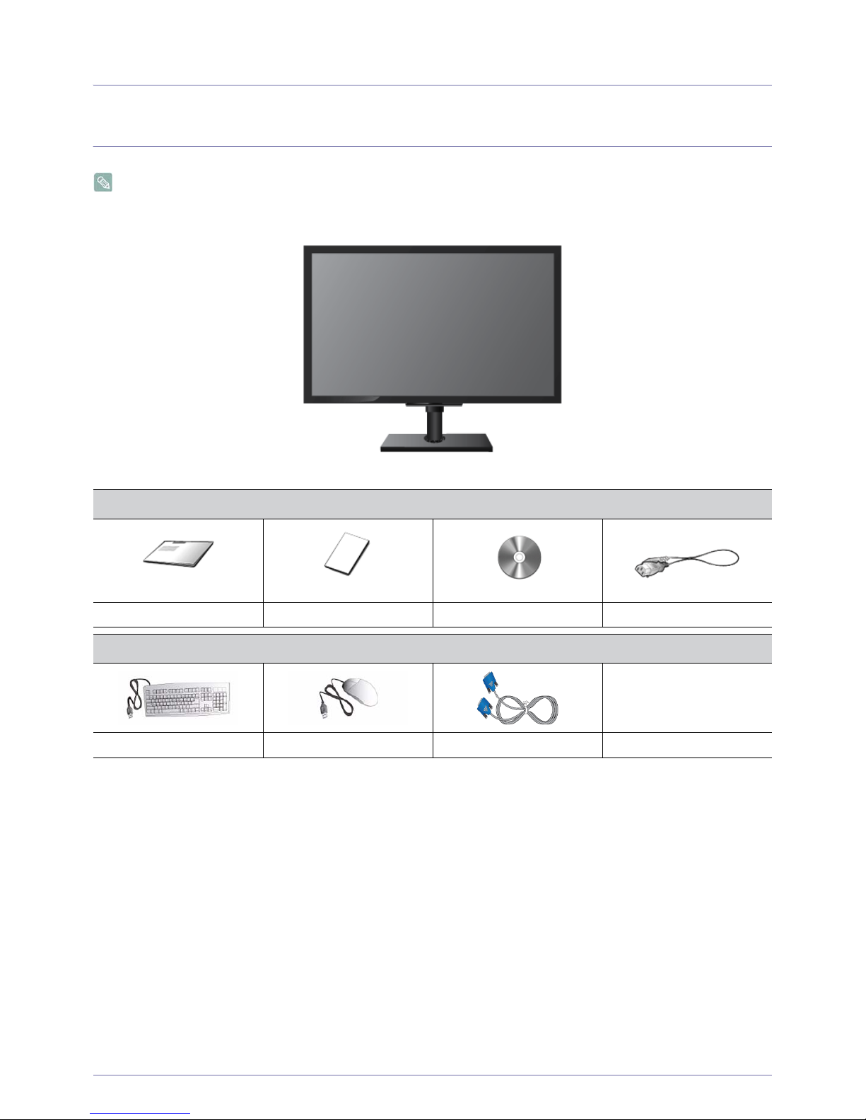
• Unpack the product and check if all of the following contents have been included.
• Store the packaging box in case you need to move the Product at a later stage.
Monitor
CONTENTS
Quick Setup Guide Product Warranty User Manual Power Cord
OPTIONAL PARTS
Keyboard (USB) Mouse (USB) D-Sub Cable
Page 12
2-2 Installing the Product
2-2 Installing the Stand
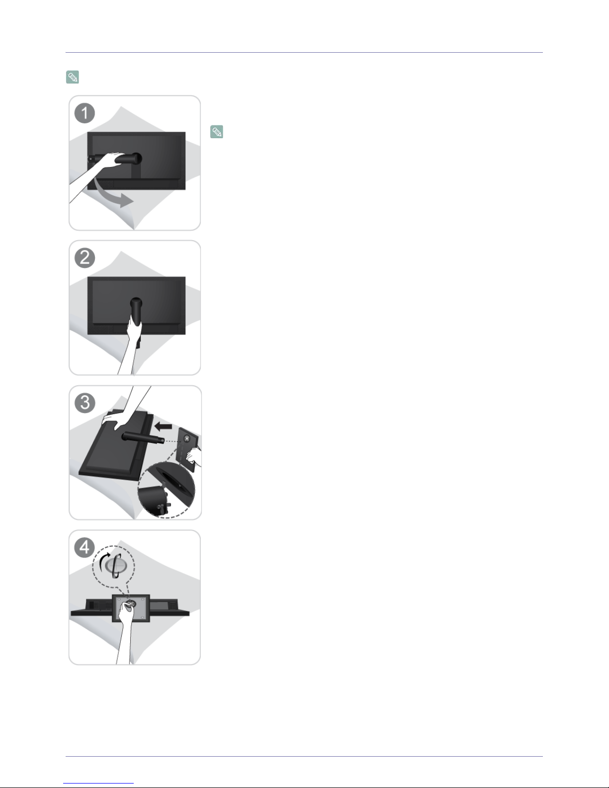
Before assembling the product, place the product down on a flat and stable surface so that the screen is facing downwards.
Place a soft cloth over the table to protect the product and place the product onto the
cloth so that the front of the product is facing downwards.
Do not remove the stopper pin before installing the base.
Hold the main body of the product with your hand as shown by the figure.
Insert the stand base into the stand connection part in the direction shown in the figure.
Turn the connecting screw at the bottom of the stand fully so that it is completely fixed.
Page 13
Installing the Product 2-2
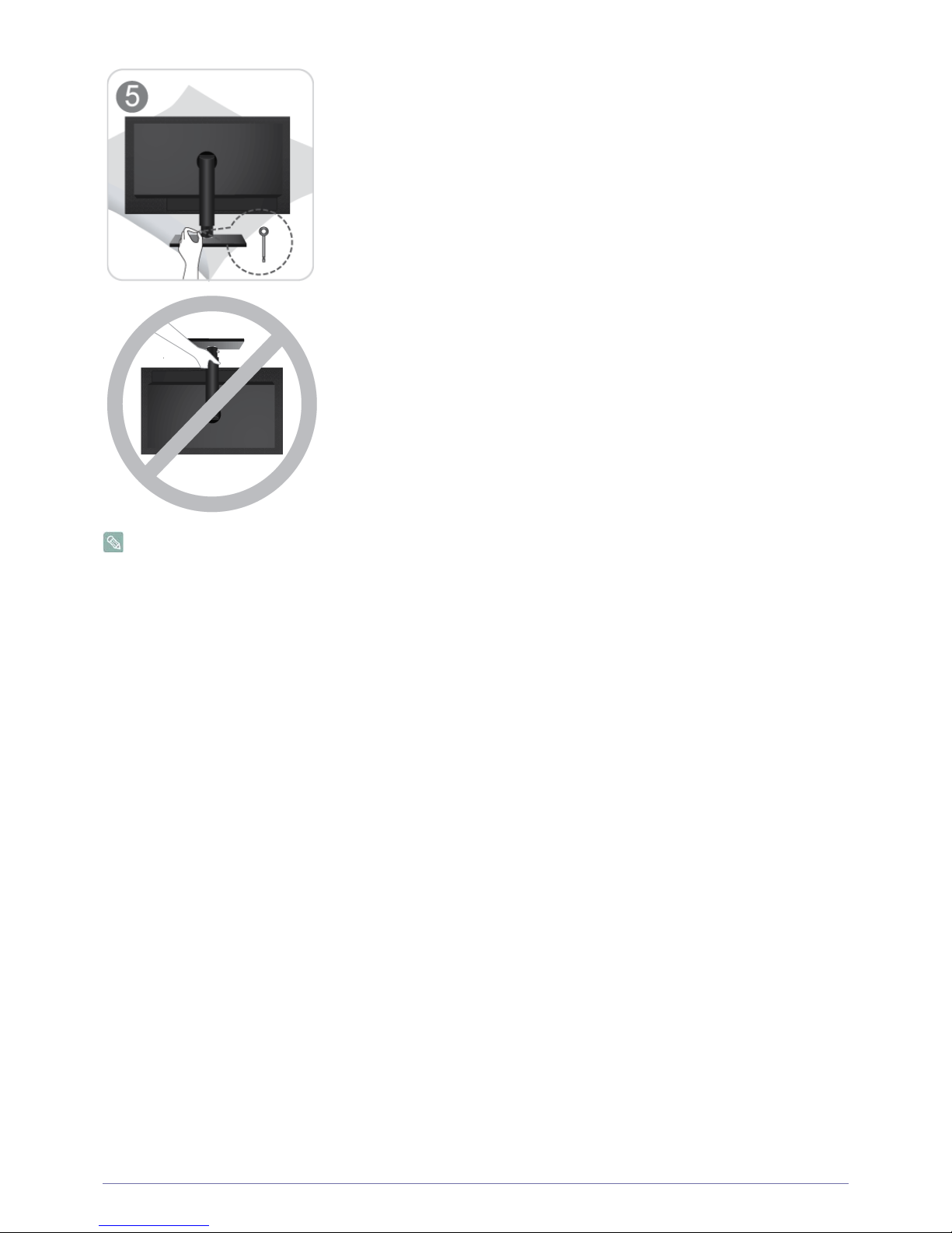
Disassembly is in the reverse order of assembly.
After the installation of the base, stand the monitor up as shown in the figure. Now you
can remove the stopper pin to adjust the stand.
- Caution
Avoid lifting the product holding only the stand.
Page 14
2-3 Installing the Product
2-3 Installing a Wall Mount
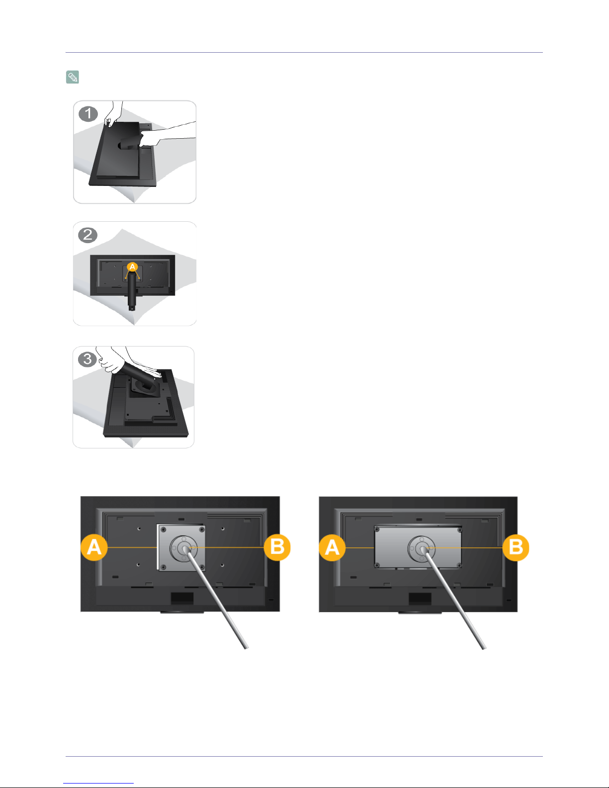
Before installation, disassemble the product according to the following steps.
This product provides a wall mount of 100 mm x 100 mm(200 mm x 100 mm) that complies with the VESA specifications.
1. Turn the product off and unplug the power cord from the wall outlet.
2. Place a soft cloth or cushion on a flat surface to protect the panel and place the product face down.
Lift up the monitor stand to the maximum angle with your left hand, and remove the back
decoration cover with your right hand, as shown in the figure.
Remove the two screws(A).
Remove the stand arm in the direction shown in the figure.
100 mm x 100 mm 200 mm x 100 mm
A. Wall Mount Base
B. Wall Mount Kit (Optional)
Page 15

Installing the Product 2-3
3. Separate the stand.
4. Align the groove of the Monitor's wall mount base with the groove in the wall mount ki and firmly fix the wall mount kit by
fastening the screws.
•If you use a screw that is longer than the standard specifications, the inside of the product may be damaged.
•For wall mounts that are not compatible with the standard VESA specifications, the length of the screw may differ depending
on the corresponding specifications.
•Do not use screws that are incompatible with the standard VESA specifications and do not assemble them using excessive
force.
This may result in damage to the product or injury due to the product falling. Samsung shall not be held liable for any damage
or injury.
•Samsung shall not be held liable for any damage to the product or injury caused by using a stand that is not compatible with
the specified specifications or due to an installation not performed by an authorized installation engineer.
•When installing the product using a wall mount, purchase a wall mount that provides at least 4 inches (10 cm) of space from
the wall.
•Samsung shall not be held liable for any problems caused by using a stand that is not compatible with the specified
specifications.
•Use a wall mount according to specifications of your country.
Page 16
2-4 Installing the Product
2-4 Connecting to your Network
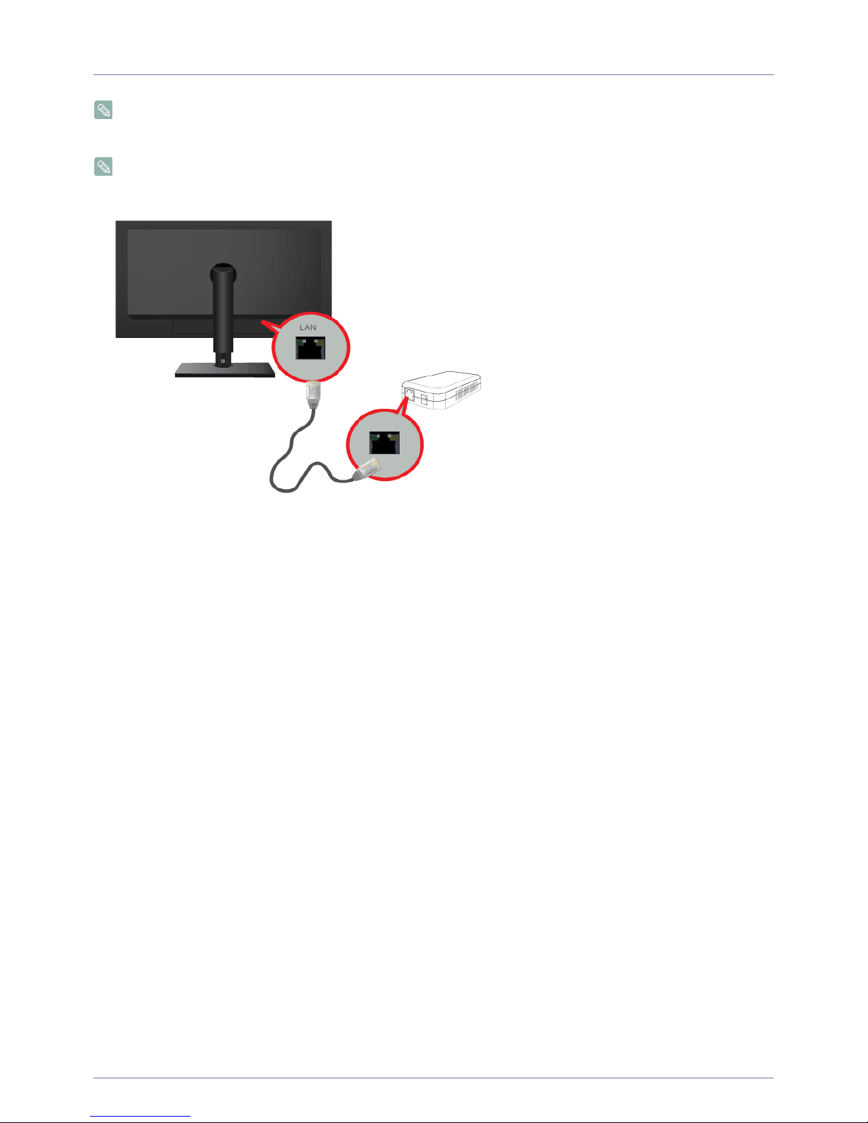
The connecting part may differ depending on the product model.
Connect between the [LAN] port on the product and your network using a LAN cable.
The two [LAN] ports are designed to work as an Internet HUB. One port can be used for input and the other port for output
to connect the product to an external Internet device. Both ports can be used for either input or output.
Page 17
Installing the Product 2-5
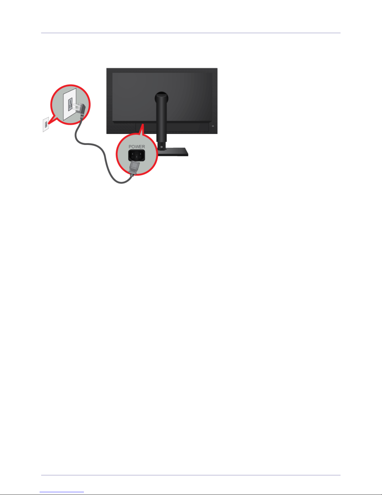
2-5 Connecting Power
To use the product, connect the power cable to a power outlet and the [POWER] port on the product.
(The input voltage is switched automatically).
Page 18
2-6 Installing the Product
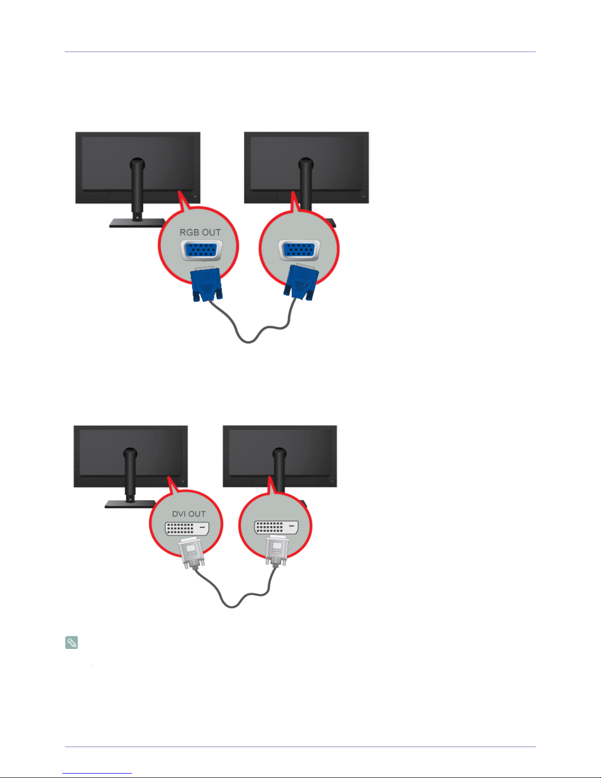
2-6 Connecting to another Monitor
Please select the right connection method for your monitor.
• When using the [RGB OUT] port
• Connect between the [RGB OUT] port on the product and the D-Sub port on your monitor using a D-Sub cable.
• When using the [DVI OUT] port
• Connect between the [DVI OUT] port on the product and the DVI port on your monitor using a DVI cable.
Connect to the [DVI OUT], [RGB OUT] port to display the same picture on another monitor such as the projector.
(For presentation purposes)
Page 19
Installing the Product 2-7
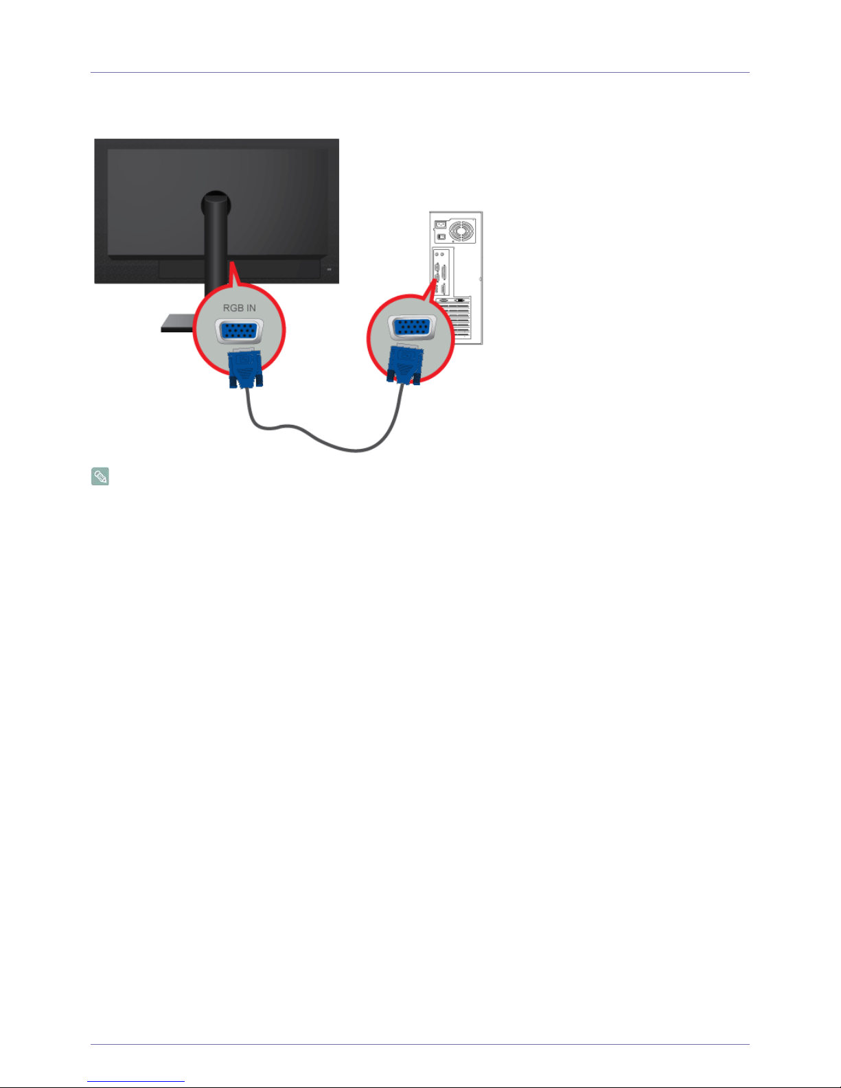
2-7 Connecting with a PC
Connect the [RGB IN] port of the product to the [D-Sub] port of your PC with a D-Sub cable.
Use the [RGB IN] port to directly connect the monitor to a PC.
Page 20
2-8 Installing the Product
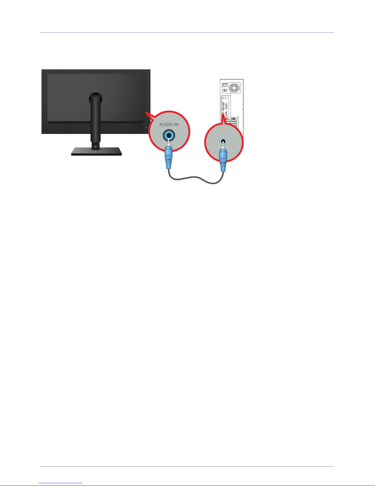
2-8 Connecting a Stereo Cable
Connect the [AUDIO IN] port on the rear side of the monitor to the sound card of the PC.
Page 21
Installing the Product 2-9
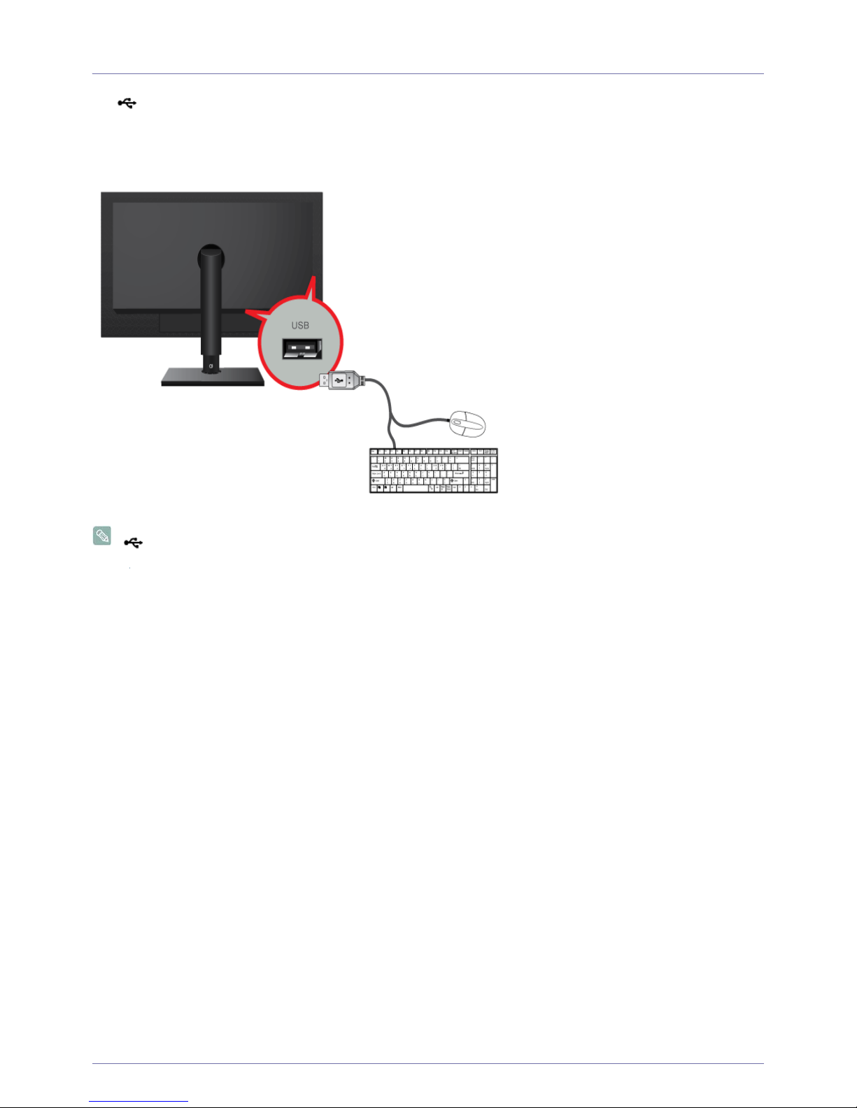
2-9 Connecting USB
The USB port of the monitor supports High-Speed Certified USB 1.1.
Connect USB devices such as a mouse, keyboard and external storage devices (DSC (Digital Still Camera), MP3, external
storage, etc.).
You can use a USB device such as a mouse, keyboard, Memory Stick, or external hard disk drive by connecting them to the
USB port of the monitor without connecting them to the PC.
Page 22
2-10 Installing the Product
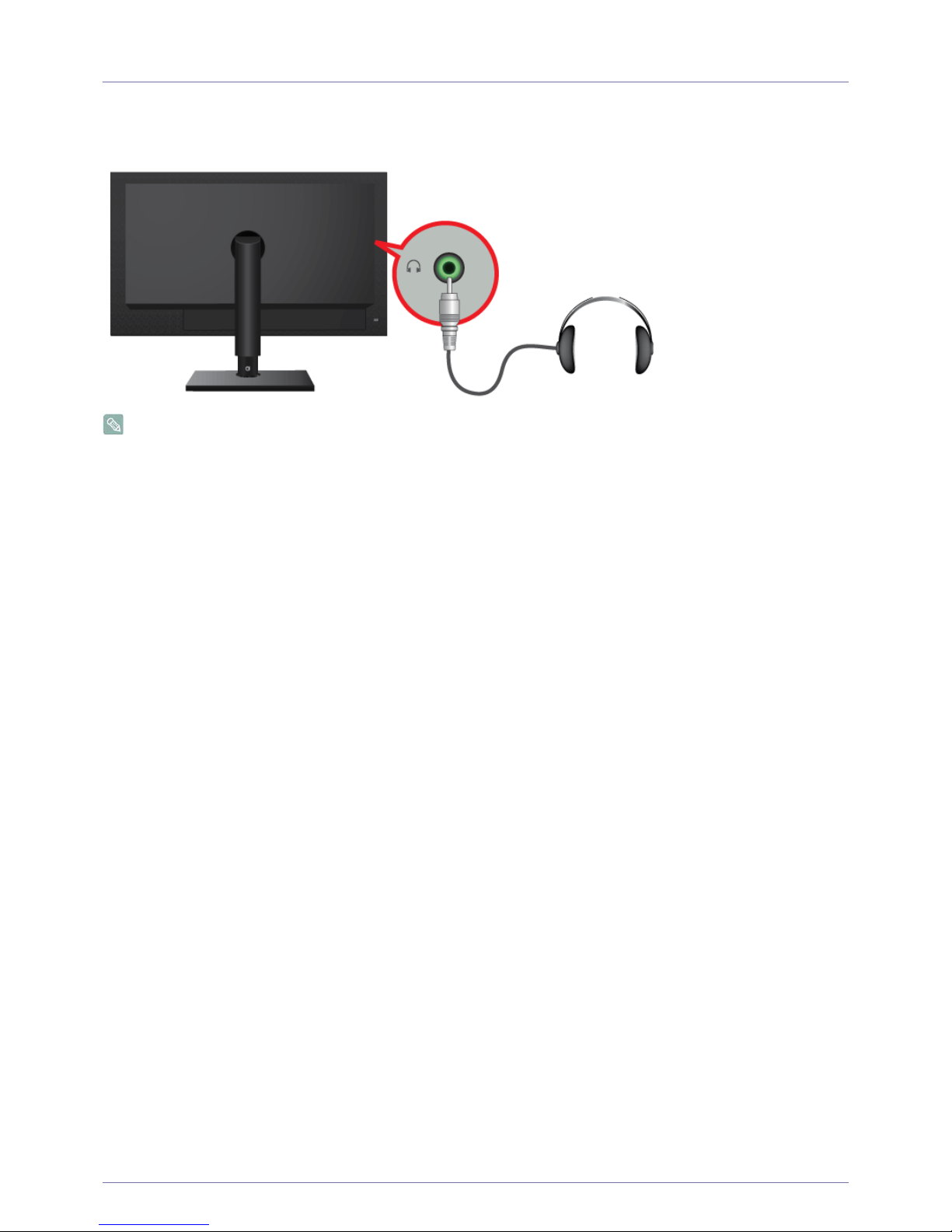
2-10 Connecting Headphones
Connect your headphones to the Headphone connection terminal.
You may connect your headphones to the monitor.
Page 23
Installing the Product 2-11
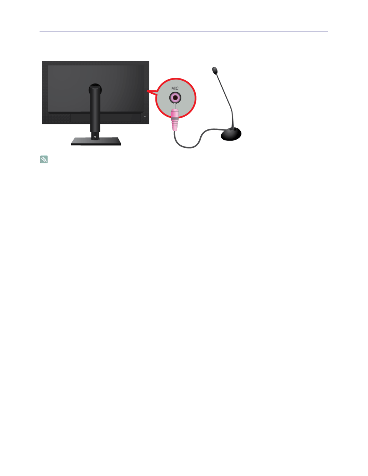
2-11 Connecting MIC
Connect the microphone cable to the MIC port on the monitor.
You may connect your microphone to the monitor.
Page 24
2-12 Installing the Product
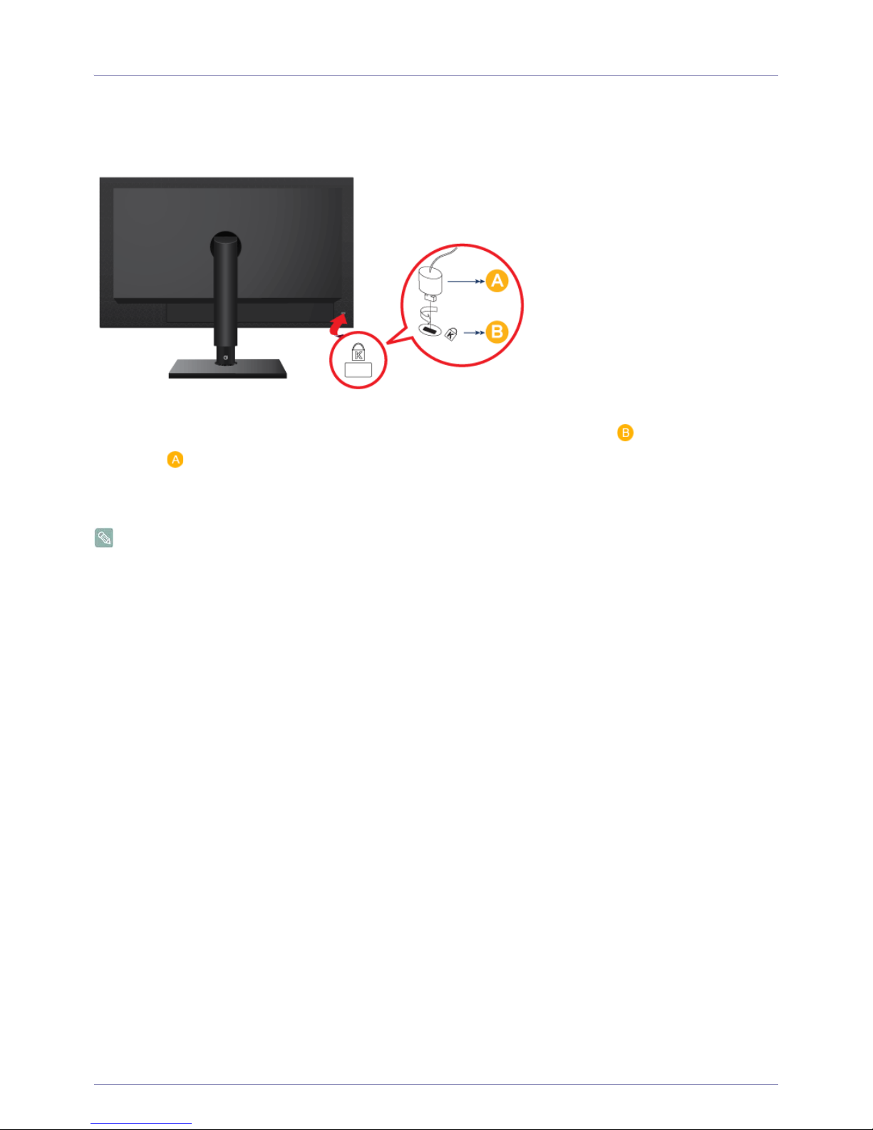
2-12 Kensington Lock
A Kensington Lock is an anti-theft device that enables users to lock the product so that they can safely use it in public locations.
Since the shape and usage of the locking device may differ depending on the model and the manufacturer, for more information,
refer to the User Manual supplied with the locking device. You have to purchase an additional locking device.
Locking the product
1. Insert the locking part of the locking device into the hole of the Kensington lock of the product ( ) and turn it in the locking
direction ( ).
2. Connect the Kensington lock cable.
3. Tie the Kensington lock cable to a desk or heavy object.
You can purchase the locking device from an electronics store or an online shop.
Page 25
Using the product 3-1
3 Using the product
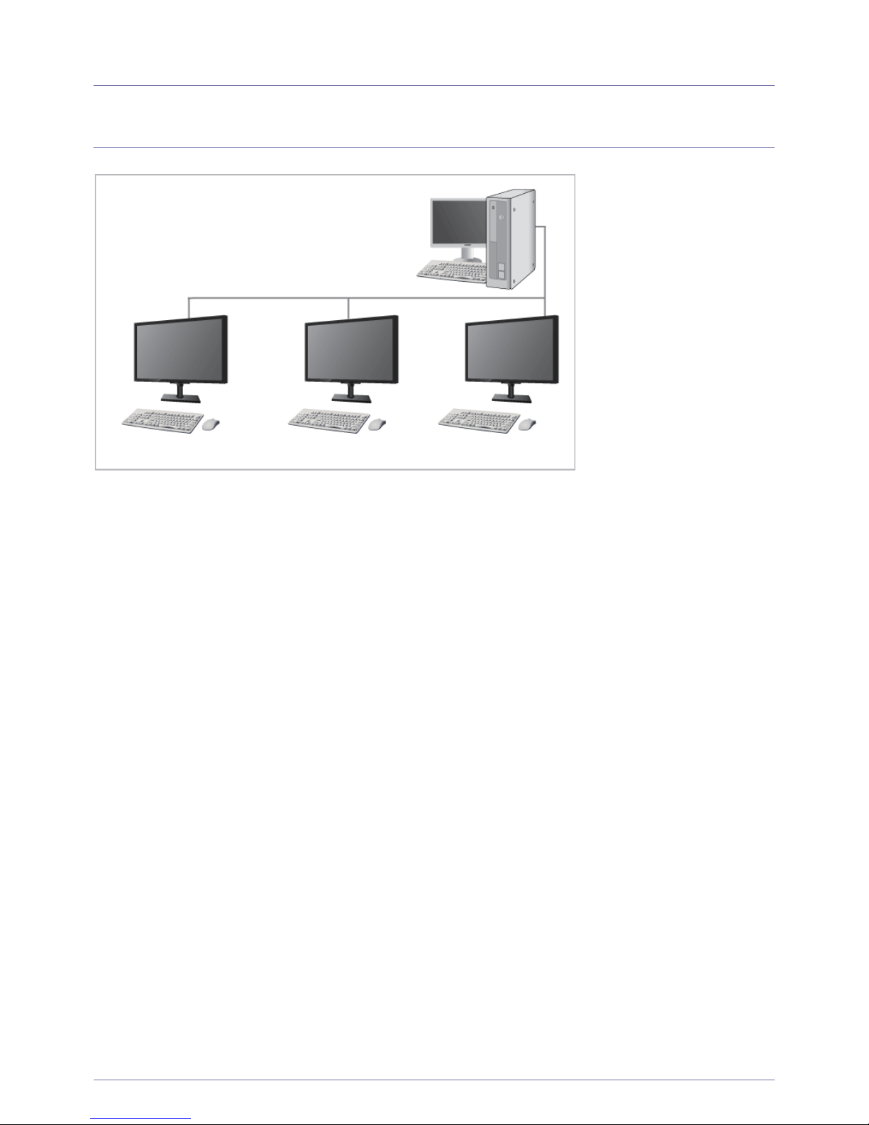
3-1 What is a PC over IP?
• This monitor can decode and display the screen of the server PC encoded and transmitted through the network (LAN) as well
as display the computer screen like a conventional monitor. This monitor shows a far more improved performance than a
normal RDP and has been designed to support a resolution of 1920*1080 pixels for high-quality graphic work.
• This monitor enables reinforced security because it is used by connecting it to a server PC and enabling you to access the
Internet, create documents and edit figures. In addition, this new-concept monitor enables you to play music, videos and
games by connecting an external input source device such as DSC, MP3, external storage device etc. to the USB port.
• This monitor can be utilized for various fields such as video conferencing and co-working by displaying the network display
screen on another display device by connecting the device through the DVI OUT port.
Page 26
3-2 Using the product
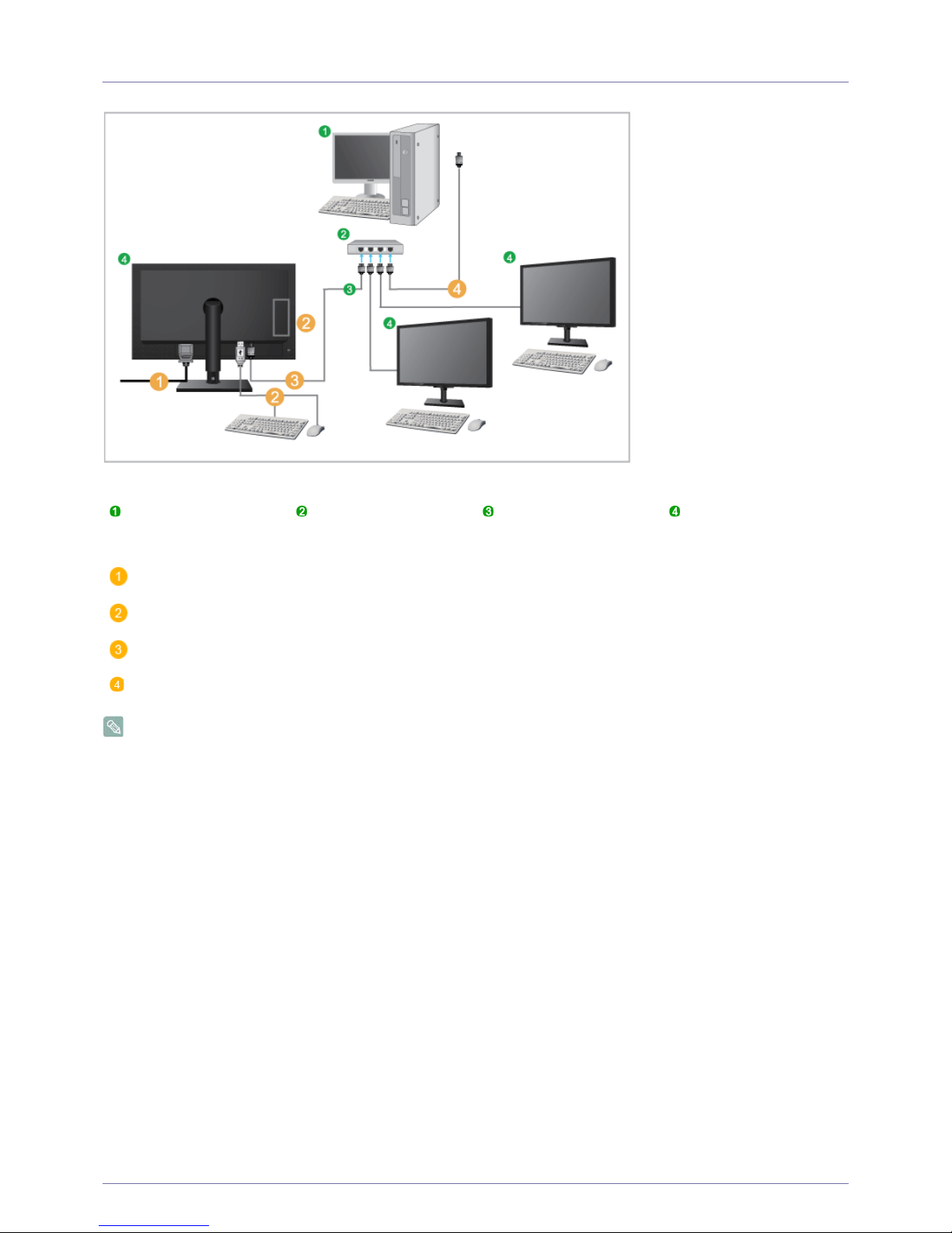
3-2 Connect to the host PC using a LAN cable
The host PC must have an IP address.
After connecting the LAN and setting the IP address, you can view the host PC screen on the monitor.
Use the USB port to connect an external storage device (DSC, MP3, external storage, etc.).
Connecting one Host PC to many client device is possible only when virtualization solution like vmware is installed in Host
PC.
Host PC Hub LAN Cable Monitor
Connect the power cord to the power terminal at the back of the monitor.
Connect the mouse and the keyboard to the USB ports.
Connect the LAN port on the back of the monitor and the hub.
Connect the hub and the LAN port of the host PC.
Page 27
Using the product 3-3
3-3 Plug & Play
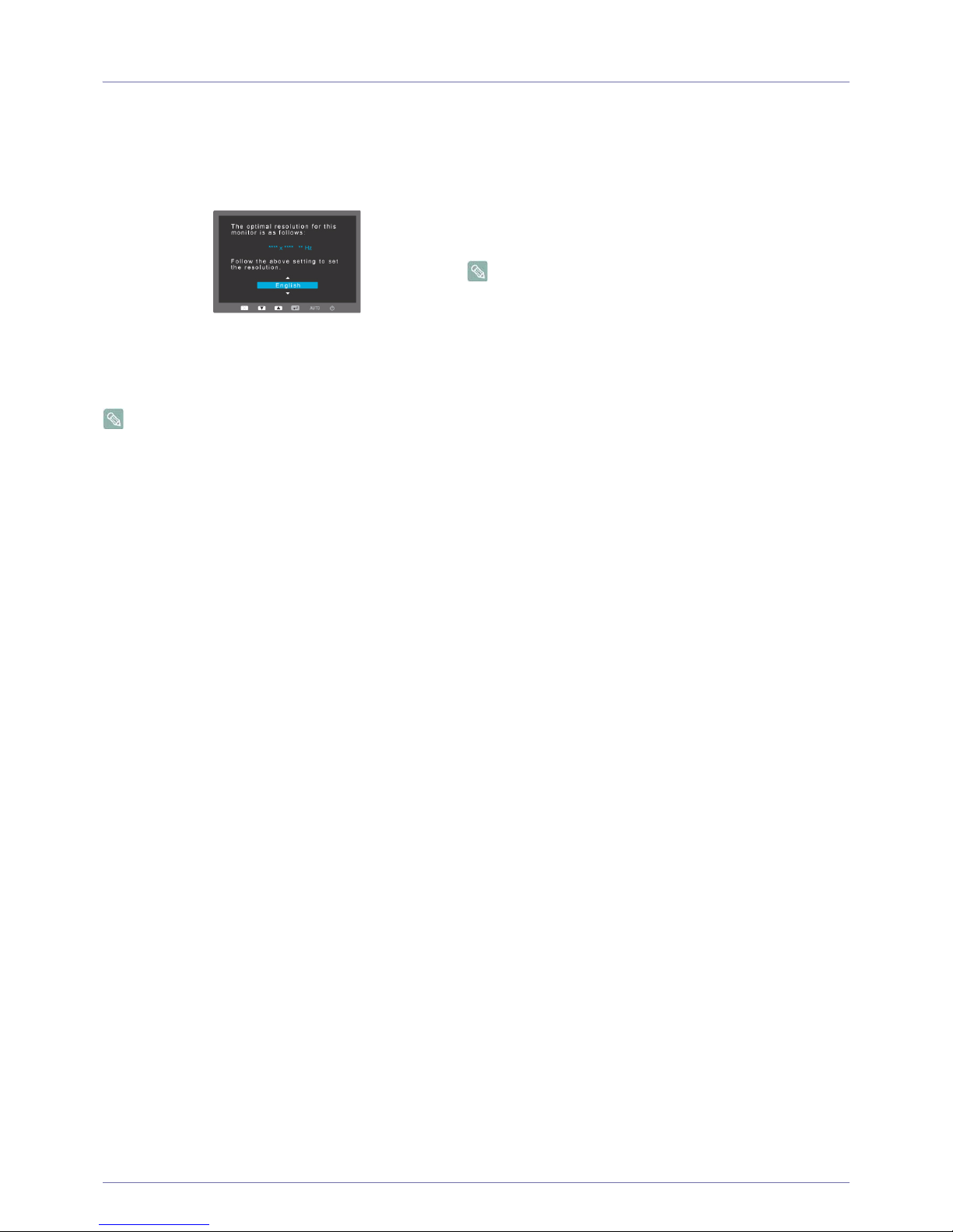
If you turn the power on after purchasing the product, a message regarding the optimal resolution setting appears on the screen.
Select a language and the optimal resolution.
• The message appears up to 3 times if the resolution has not been set to the optimal resolution.
▲/▼ : You can select a language with these buttons.
MENU : If you press this button, the message disappears.
To set the resolution to the optimal resolution.
• Right-click over the Desktop and select 'Properties'
from the pop-up menu.
• In the 'Settings' tab, set the resolution to the optimal
resolution.
Page 28
3-4 Using the product
3-4 Standard Signal Mode Table
The LCD monitor has one optimal resolution for the best visual quality depending on the screen size due to the inherent
characteristics of the panel, unlike for a CDT monitor.
Therefore, the visual quality will be degraded if the optimal resolution is not set for the panel size. It is recommended setting
the resolution to the optimal resolution of the product.
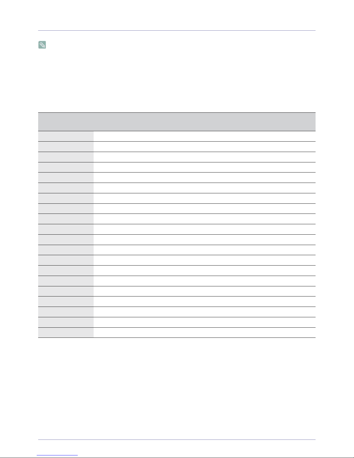
If the signal from the PC is one of the following standard signal modes, the screen is set automatically. However, if the signal from
the PC is not one of the following signal modes, a blank screen may be displayed or only the Power LED may be turned on.
Therefore, configure it as follows, referring to the User Manual of the graphics card.
NC190
DISPLAY MODE
HORIZONTAL
FREQUENCY (KHZ)
VERTICAL
FREQUENCY (HZ)
PIXEL CLOCK (MHZ)
SYNC POLARITY (H/
V)
IBM, 640 x 350 31.469 70.086 25.175 +/-
IBM, 720 x 400 31.469 70.087 28.322 -/+
MAC, 640 x 480 35.000 66.667 30.240 -/-
MAC, 832 x 624 49.726 74.551 57.284 -/-
MAC, 1152 x 870 68.681 75.062 100.000 -/-
VESA, 640 x 480 31.469 59.940 25.175 -/-
VESA, 640 x 480 37.500 75.000 31.500 -/-
VESA, 800 x 600 35.156 56.250 36.000 +/+
VESA, 800 x 600 37.879 60.317 40.000 +/+
VESA, 800 x 600 48.077 72.188 50.000 +/+
VESA, 800 x 600 46.875 75.000 49.500 +/+
VESA, 1024 x 768 48.363 60.004 65.000 -/-
VESA, 1024 x 768 56.476 70.069 75.000 -/-
VESA, 1024 x 768 60.023 75.029 78.750 +/+
VESA, 1152 x 864 67.500 75.000 108.000 +/+
VESA, 1280 x 800 49.702 59.810 83.500 -/+
VESA, 1280 x 800 62.795 74.934 106.500 -/+
VESA, 1280 x 960 60.000 60.000 108.000 +/+
VESA, 1280 x 1024 63.981 60.020 108.000 +/+
VESA, 1280 x 1024 79.976 75.025 135.000 +/+
Page 29

Using the product 3-4
Horizontal Frequency
The time taken to scan one line from the left-most position to the right-most position on the screen is called the horizontal cycle
and the reciprocal of the horizontal cycle is called the horizontal frequency. The horizontal frequency is represented in kHz.
Vertical Frequency
A panel must display the same picture on the screen tens of times every second so that humans can see the picture. This
frequency is called the vertical frequency. The vertical frequency is represented in Hz.
DISPLAY MODE
HORIZONTAL
FREQUENCY (KHZ)
VERTICAL
FREQUENCY (HZ)
PIXEL CLOCK (MHZ)
SYNC POLARITY (H/
V)
IBM, 640 x 350 31.469 70.086 25.175 +/-
IBM, 720 x 400 31.469 70.087 28.322 -/+
MAC, 640 x 480 35.000 66.667 30.240 -/-
MAC, 832 x 624 49.726 74.551 57.284 -/-
MAC, 1152 x 870 68.681 75.062 100.000 -/-
VESA, 640 x 480 31.469 59.940 25.175 -/-
VESA, 640 x 480 37.861 72.809 31.500 -/-
VESA, 640 x 480 37.500 75.000 31.500 -/-
VESA, 800 x 600 35.156 56.250 36.000 +/+
VESA, 800 x 600 37.879 60.317 40.000 +/+
VESA, 800 x 600 48.077 72.188 50.000 +/+
VESA, 800 x 600 46.875 75.000 49.500 +/+
VESA, 1024 x 768 48.363 60.004 65.000 -/-
VESA, 1024 x 768 56.476 70.069 75.000 -/-
VESA, 1024 x 768 60.023 75.029 78.750 +/+
VESA, 1152 x 864 67.500 75.000 108.000 +/+
VESA, 1280 x 800 49.702 59.810 83.500 -/+
VESA, 1280 x 800 62.795 74.934 106.500 -/+
VESA, 1280 x 960 60.000 60.000 108.000 +/+
VESA, 1280 x 1024 63.981 60.020 108.000 +/+
VESA, 1280 x 1024 79.976 75.025 135.000 +/+
VESA, 1440 x 900 55.935 59.887 106.500 -/+
VESA, 1440 x 900 70.635 74.984 136.750 -/+
VESA, 1600 x 1200 75.000 60.000 162.000 +/+
VESA, 1680 x 1050 65.290 59.954 146.250 -/+
VESA, 1920 x 1080 67.500 60.000 148.500 +/+
NC240
Page 30
3-5 Using the product
3-5 Installing the Device Driver
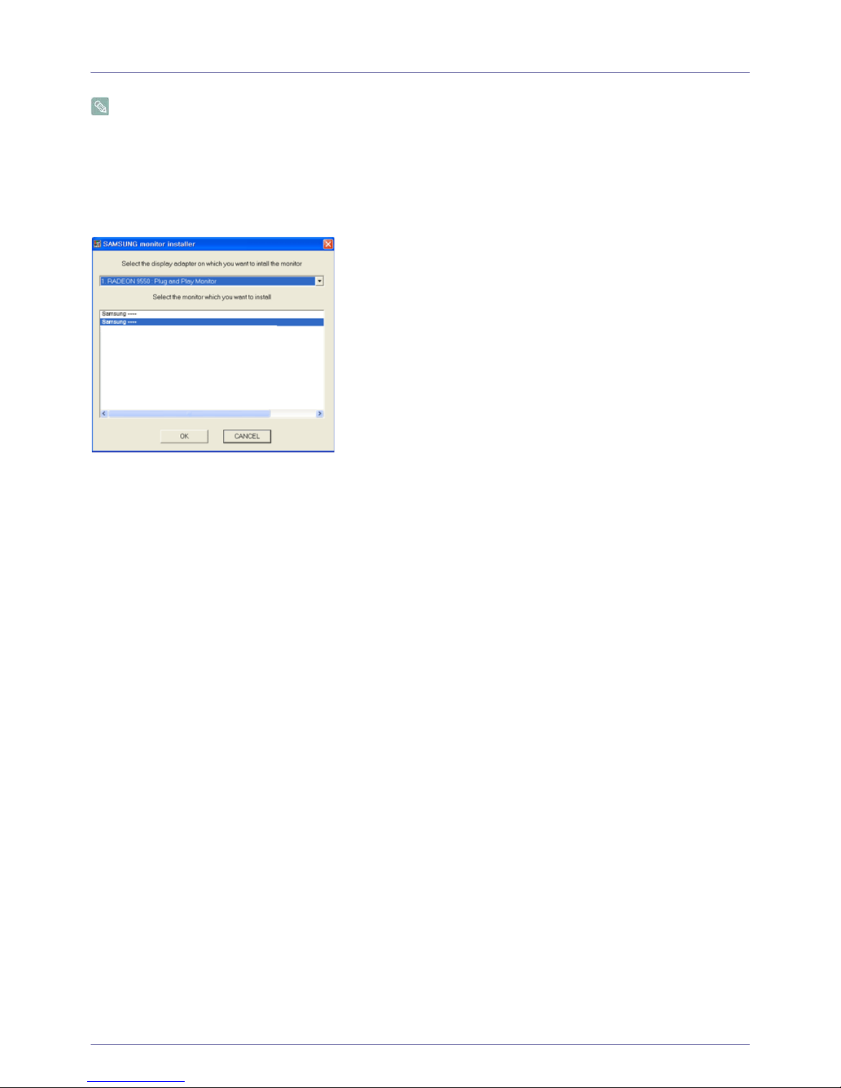
If you install the device driver, you can set up the appropriate resolution and frequency for the product. The device driver is
included on the CD-ROM supplied with the product. If the supplied drive file is corrupted, please visit the Samsung
Electronics website(http://www.samsung.com/), and download the driver.
1. Insert the driver installation CD-ROM into the CD-ROM drive.
2. Click on "Windows Driver".
3. Select the model of your product from the model list.
4. Complete the remaining installation steps according to the instructions displayed on the screen.
5. Check if the appropriate resolution and screen refresh rate are displayed in the Control Panel settings. For more information,
refer to the document about the Windows operating system.
Page 31
Using the product 3-6
3-6 Product Operating Buttons
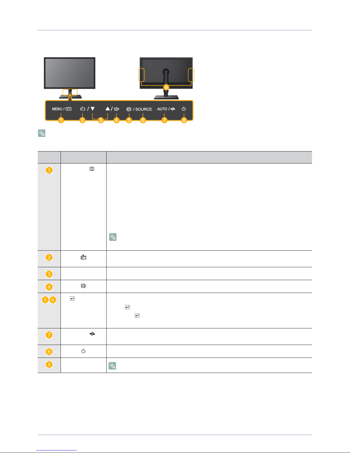
Product Operating Buttons
The buttons are located on the bottom of the product.
Icon Description
MENU/
Press this button to view the On Screen Display (OSD).
This button is also used to exit the OSD or to return to a higher-level OSD menu
* Key Lock
This function locks the buttons on the front of the product to prevent the current settings from
being changed by others.
Lock: Press and hold the MENU button for 5 seconds. The key lock mode will be enabled.
Unlock: Press and hold the MENU button for 5 seconds when the key lock is enabled. The key
lock mode will be disabled.
When the key lock mode is enabled, all the buttons on the front of the product are
disabled.
Press the button at least 2sec to connect to the host PC in Client mode. In order to turn the
host PC off, press the button more than 2 sec, being connected to the host PC.
▲/▼ Adjust items in the menu.
When OSD is not on the screen, push the button to adjust volume.
/SOURCE
Use this button to select a function
Press [ /SOURCE] to select the video signal from a connected device while the OSD is off.
(When the [ /SOURCE] button is pressed to change the input mode, a message appears in
the upper left of the screen displaying the current mode).
AUTO /
In <Analog> mode, this button is used for auto adjustments. In <Client> mode, it is used to disconnect from the server.
Press this button to turn the product on or off
Speaker
Applicable to the 24-inch model only.
Page 32
3-7 Using the product
3-7 Using the Screen Adjustment Menu (OSD: On Screen Display)
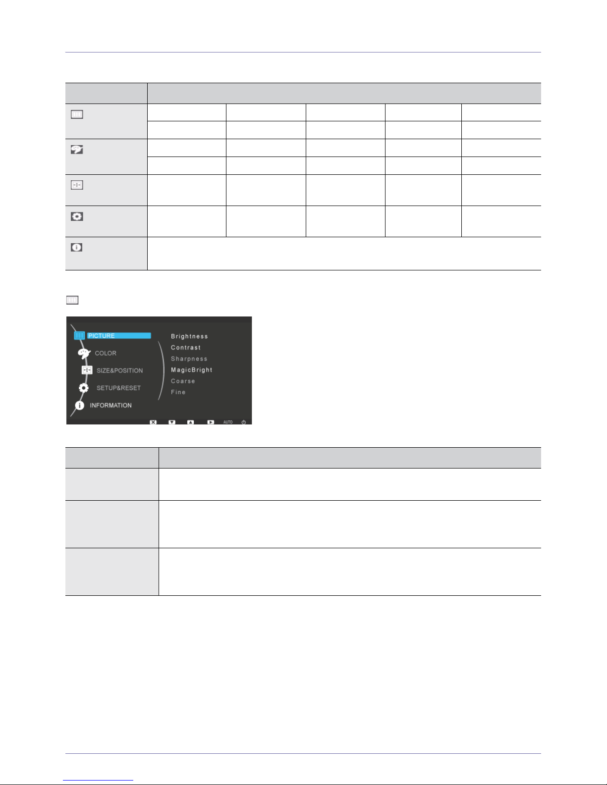
The Screen Adjustment Menu (OSD: On Screen Display) Structure
PICTURE
Top Menus Sub Menus
PICTURE
Brightness Contrast Sharpness MagicBright Coarse
Fine
COLOR
MagicColor Red Green Blue Color Tone
Color Effect Gamma
SIZE & POSI-
TION
H-Position V-Position Image Size Menu H-Position Menu V-Position
SETUP&RESE
T
Reset Menu Transpar-
ency
Language Display Time
INFORMA-
TION
-
Menu Description
Brightness Controls the screen brightness.
This menu is unavailable when <MagicBright> is set to <Dynamic Contrast> mode.
Contrast Controls the contrast of the pictures displayed on the screen
This menu is unavailable when <MagicBright> is set to <Dynamic Contrast> mode.
This menu is unavailable when <MagicColor> is set to <Full> mode or <Intelligent> mode.
Sharpness Controls the clarity of details of pictures displayed on the screen
This menu is unavailable when <MagicBright> is set to <Dynamic Contrast> mode.
This menu is unavailable when <MagicColor> is set to <Full> mode or <Intelligent> mode.
Page 33
Using the product 3-7
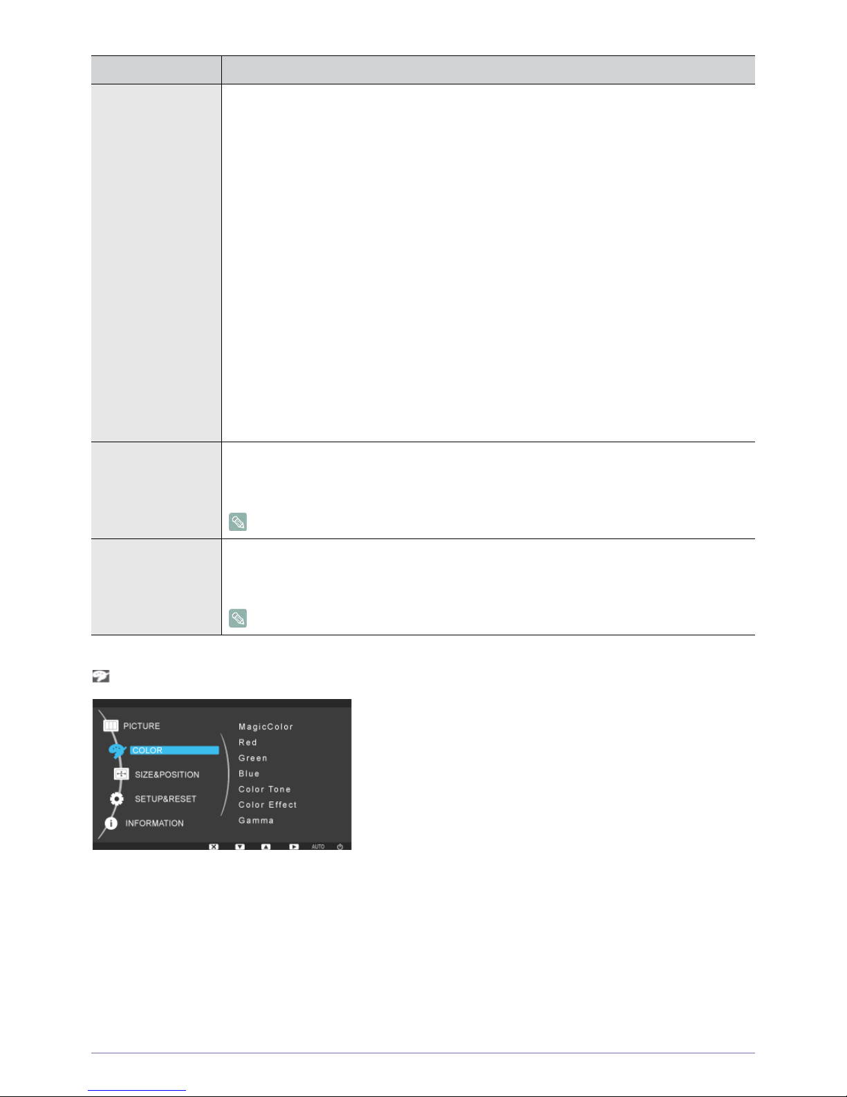
COLOR
MagicBright Provides preset picture settings optimized for various user environments such as editing a document,
surfing the Internet, playing games, watching sports or movies and so on.
• <Custom>
If the preset picture modes are not sufficient, you can configure the <Brightness> and <Contrast>
directly using this mode.
• <Text>
This mode provides the picture setting appropriate for editing a document.
•<Internet>
This mode provides the picture setting appropriate for surfing the Internet (text + picture).
•<Game>
This mode provides the picture setting appropriate for playing games that include lots of graphics and
that require a fast screen refresh rate.
•<Sport>
This mode provides the picture setting appropriate for watching sports games that include lots of
movement.
•<Movie>
This mode provides brightness and sharpness settings similar to those of a TV for the best
entertainment environment (movie, DVD, etc.).
• <Dynamic Contrast>
Controls the picture contrast automatically so that bright and dark pictures are balanced overall.
Coarse Removes vertical noise lines (line pattern) from the screen.
The location of the screen may be changed after the adjustment. In this case, move the screen so
that the screen is displayed at the center of the display panel using the <H-Position> menu.
This function is only available in analog mode.
Fine Removes horizontal noise lines (line pattern) from the screen.
If you cannot remove the noise completely with the <Fine> function, adjust the <Coarse> and then
use the <Fine> function again.
This function is only available in analog mode.
Menu Description
Page 34
3-7 Using the product
<Color> feature is not available when <MagicBright> is set to <Dynamic Contrast> mode.
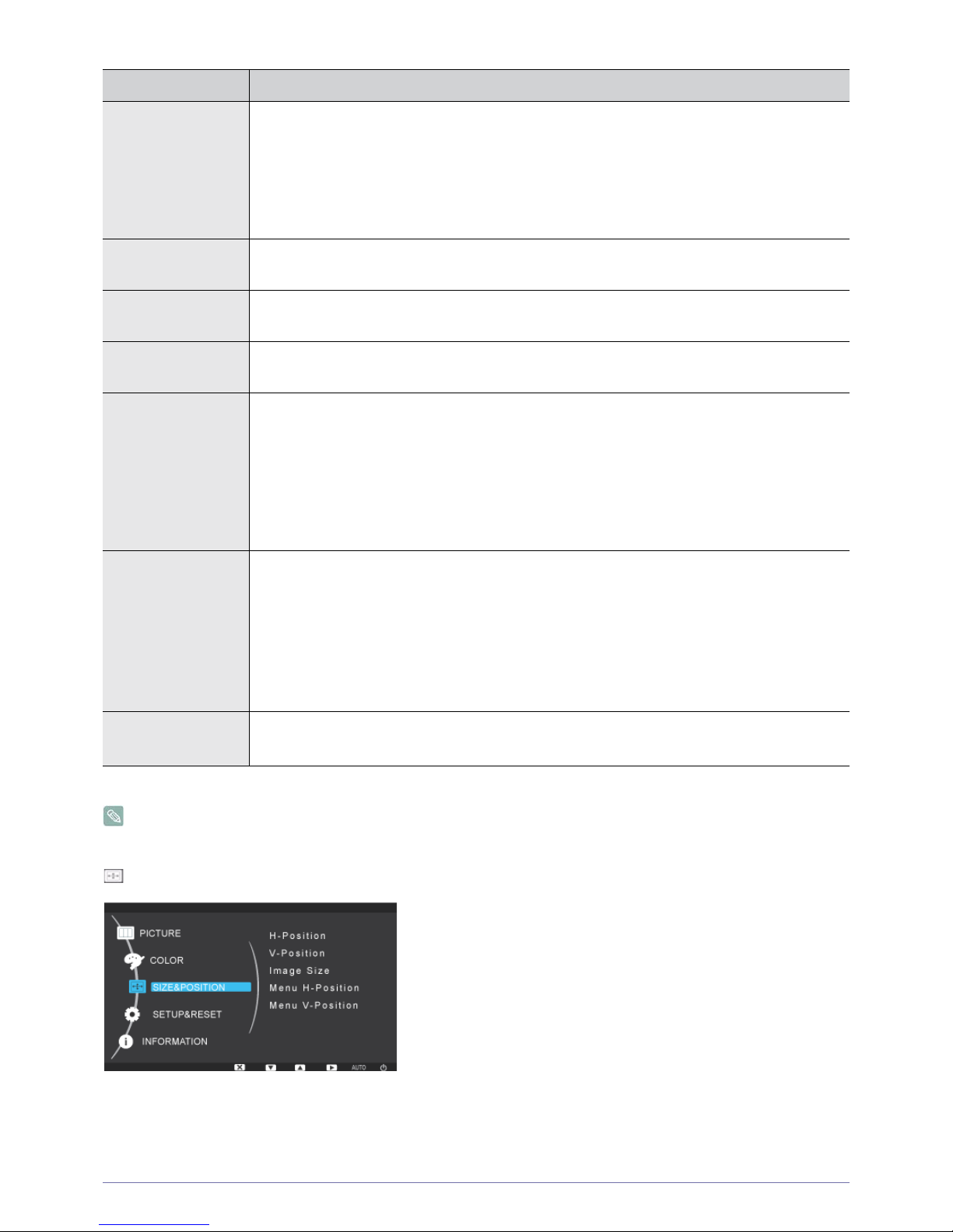
SIZE & POSITION
Menu Description
MagicColor Expresses natural colors more clearly without changing the picture quality by using proprietary digital
picture quality improvement technology developed by Samsung Electronics.
• <Off> - Turns the MagicColor function off.
• <Demo> - You can compare the pictures processed by MagicColor with the original pictures.
• <Full> - Provides a clearer picture including areas corresponding to skin color.
• <Intelligent> - Improves the chroma of pictures except for areas corresponding to skin color.
Red You can adjust the red color value according to your preference.
This menu is unavailable when <MagicColor> is set to <Full> mode or <Intelligent> mode.
Green You can adjust the green color value according to your preference.
This menu is unavailable when <MagicColor> is set to <Full> mode or <Intelligent> mode.
Blue You can adjust the blue color value according to your preference.
This menu is unavailable when <MagicColor> is set to <Full> mode or <Intelligent> mode.
Color Tone You can set the color temperature according to your preference.
• <Cool> - Sets the color temperature of the screen to a cooler color.
• <Normal> - Sets the color temperature of the screen to the standard color temperature.
• <Warm> - Sets the color temperature of the screen to a warmer color.
• <Custom> - Select this menu to set the color temperature manually.
If you do not like the preset color temperatures, you can manually adjust the colors of <Color Effect>.
This menu is unavailable when <MagicColor> is set to <Full> mode or <Intelligent> mode.
Color Effect You can change the overall atmosphere by changing the color of pictures.
This menu is unavailable when <MagicColor> is set to <Full> mode or <Intelligent> mode.
• <Off> - Turns the color effect function off.
• <Grayscale> -Displays pictures in black and white.
• <Green> - Displays pictures in green monochrome color.
• <Aqua> - Displays pictures in aqua monochrome color.
• <Sepia> - Displays pictures in sepia monochrome color.
Gamma Using this menu, you can change the intensity of the colors of medium brightness.
• <Mode1> - <Mode2> - <Mode3>
Page 35
Using the product 3-7
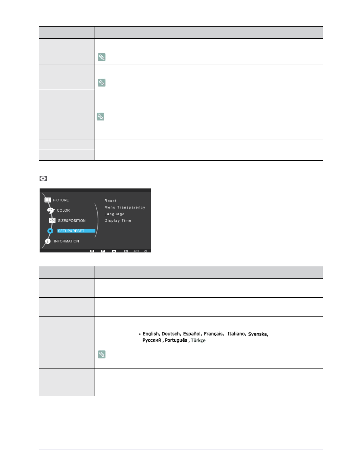
SETUP&RESET
Menu Description
H-Position Moves the position of the display area on the screen horizontally.
This function is only available in analog mode.
V-Position Moves the position of the display area on the screen vertically.
This function is only available in analog mode.
Image Size • <Auto> - The picture is displayed at the aspect ratio of the input signal.
• <Wide> - The picture is displayed in full screen regardless of the aspect ratio of the input signal.
• A signal not in the standard mode table is not supported.
• If the resolution is set to the optimal resolution, the aspect ratio does not change whether the
<Image Size> is set to <Auto> or <Wide>.
Menu H-Position You can adjust the horizontal position of the OSD.
Menu V-Position You can adjust the vertical position of the OSD.
Menu Description
Reset Use this function to restore the visual quality and color settings to the factory defaults.
• <No> - <Yes>
Menu Transparency You can select the transparency of the OSD.
• <Off> - <On>
Language Select a language for the OSD.
The selected language is only applied to the product OSD. This setting does not affect the other
functions of the PC.
Display Time The OSD automatically disappears if no action is taken by the user.
You can determine the time to wait before the OSD is hidden.
• <5 sec> - <10 sec> - <20 sec> - <200 sec>
Page 36
3-7 Using the product
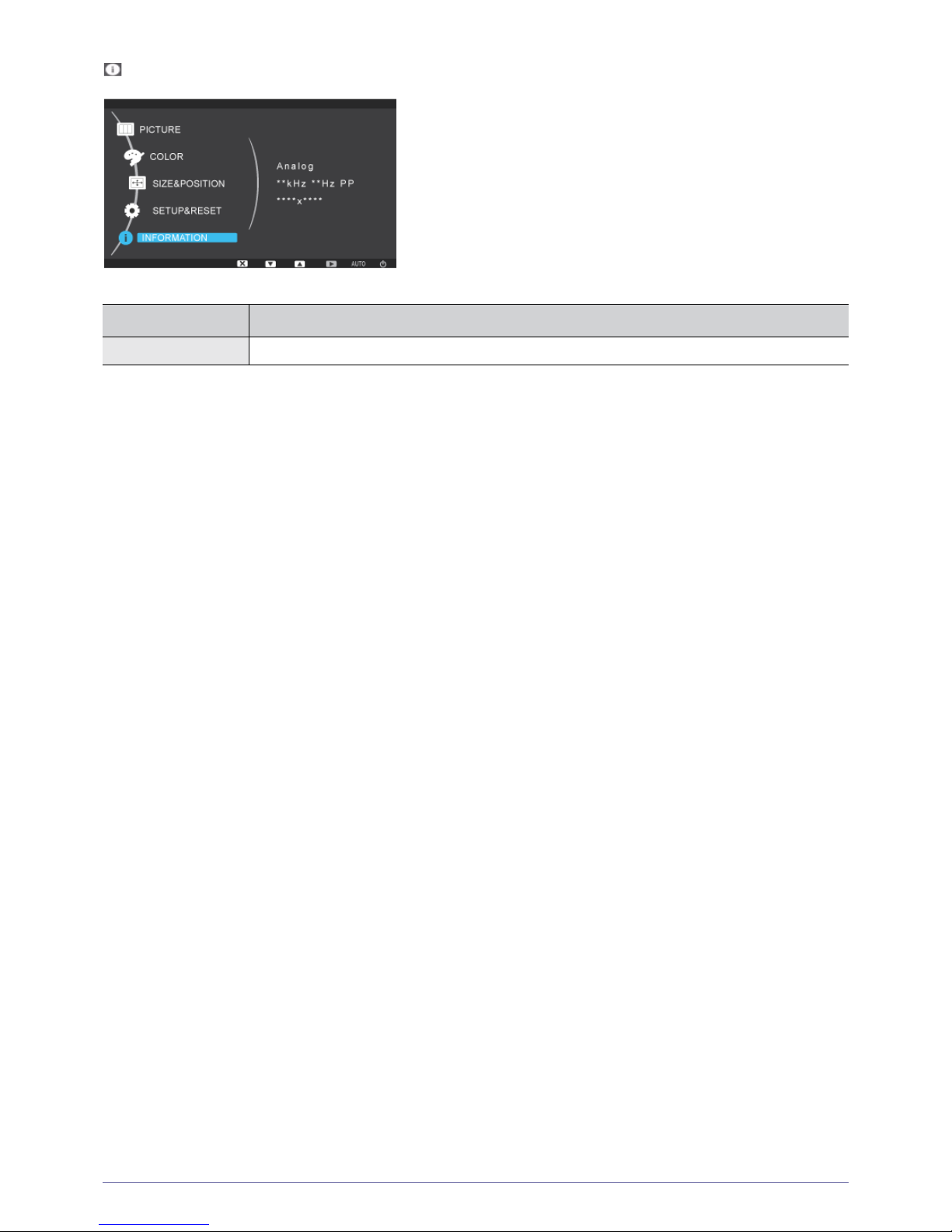
INFORMATION
Menu Description
INFORMATION Shows the frequency and resolution set on the PC.
Page 37

Installing the Software 4-1
4 Installing the Software
4-1 PCoIP
On Screen Display (OSD)
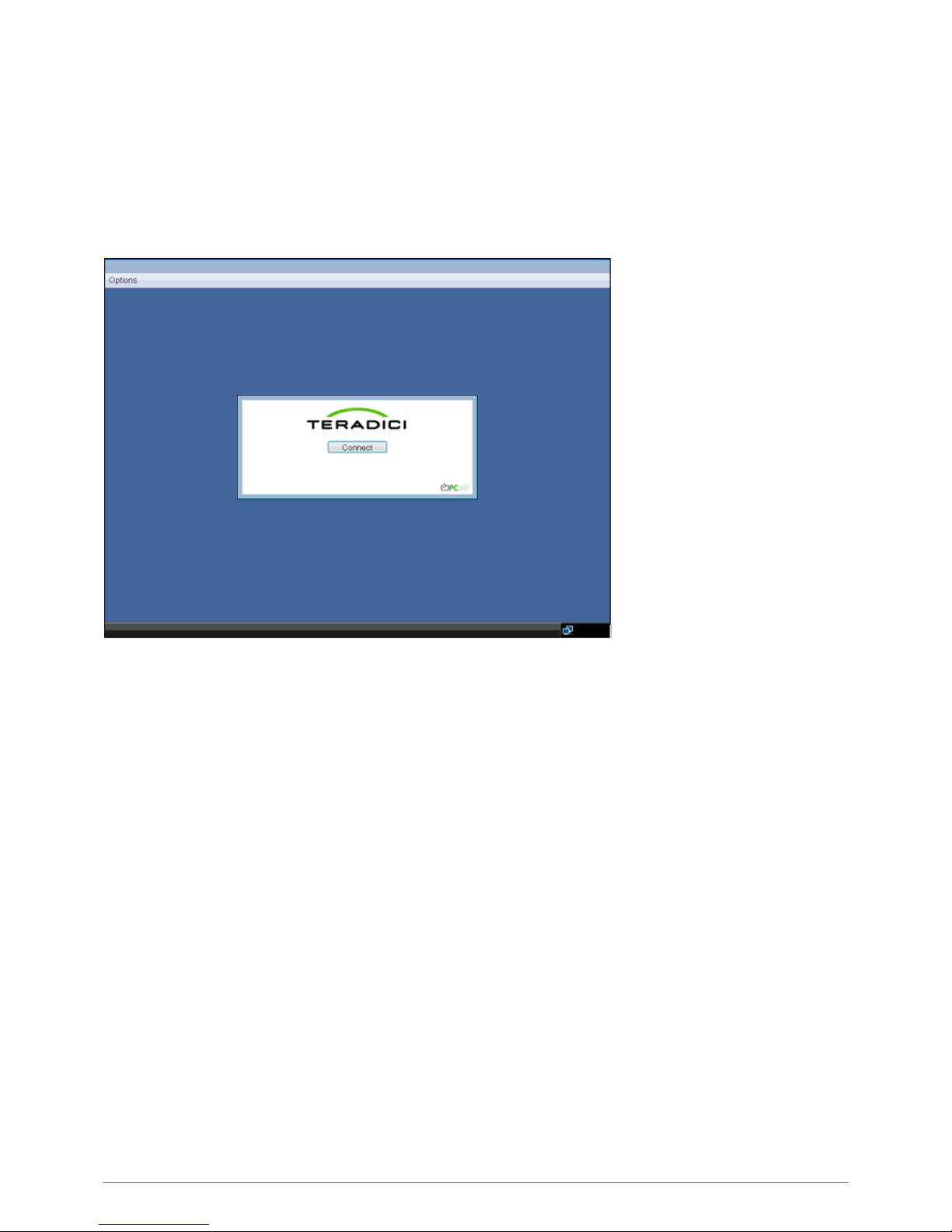
The On Screen Display (OSD) local GUI (Portal only) is displayed to the user when the device is powered on and a PCoIP
session is not in progress. The OSD provides a mechanism to connect to a host device via the Connect Screen. The Connect
Screen is presented to the user on startup.
The Connect Screen also allows access to the Options Window. The Options Window provides a subset of the functionality
provided by the Administrative Web Interface described in Section 1. The Options Window is accessible through the <Options>
button on the Connect Screen. An administrative password is required to change Portal options.
Page 38
4-1 Installing the Software
Connect Screen
The Connect Screen is shown on startup except when the Portal has been configured for a managed start-up or auto-reconnect.
The logo displayed above the <Connect> button can be changed by uploading a replacement image via the Administrative Web
Interface.
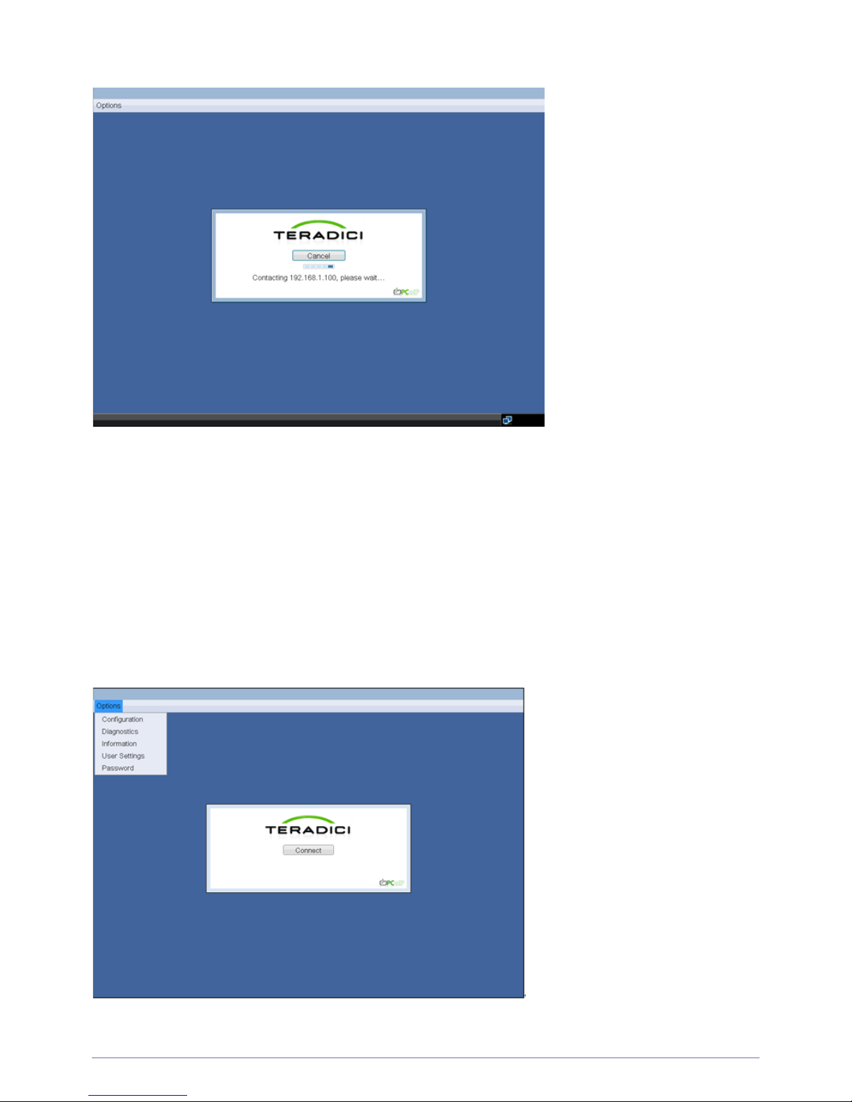
Figure 2-1: OSD Connect Screen
Connect Button
Selecting the Connect button initiates a PCoIP or RDP session, depending on the session settings. While the PCoIP
connection is pending, the OSD local GUI will display a “Connection Pending” message. When the connection is established,
the OSD local GUI will disappear and be replaced with the session image.
Page 39
Installing the Software 4-1
OSD <Options> Menu
Selecting the <Options> menu will produce a list of selections. The OSD <Options> menu contains:
• <Configuration>
• <Diagnostics>
• <Information>
• <User Settings>
• <Password>
Selecting one of the selections will produce a settings window.
OSD <Options> Menu
Figure 2-2: OSD Connect Screen (Connecting)
Figure 2-3:
Page 40
4-1 Installing the Software
<Configuration> Window
The <Configuration> window allows the administrator to access window tabs with settings that define how the Portal operates
and interacts with its environment.
The tabs in the <Configuration> window are:
•<Network>
• <Label>
• <Connection Management>
• <Discovery>
• <Session>
• <RDP>
• <Language>
•<OSD>
•<Reset>
• <VMware View>
Each tab has <OK>, <Cancel>, and <Apply> buttons that allow the administrator to accept or cancel the setting changes made on
the tab.
Some PCoIP devices have password protection disabled and do not require a password to login into the administration
webpages or access the OSD parameters. Password protection for the Log In page and OSD can be enabled through
PCoIP Management Console.
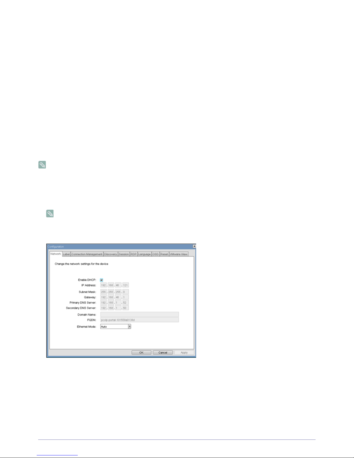
<Network> Tab
The <Network> tab allows an administrator to set the Portal network parameters.
The Network parameters can also be configured using the Webpage Administration Interface.
<Network> Configuration
• <Enable DHCP>
When <Enable DHCP> is enabled, the device will contact a DHCP server to be assigned an IP address, subnet mask,
gateway IP address and DNS servers. When disabled, the device requires these parameters to be set manually.
• <IP Address>
The IP Address field is the device’s <IP address>. If DHCP is disabled, this field is required. If DHCP is enabled, this field
is not editable. This field must be a valid IP address, and if an invalid IP address is entered, the OSD will prompt the
administrator to correct it.
• <Subnet Mask>
The <Subnet Mask> field is the device’s subnet mask. If DHCP is disabled, this field is required. If DHCP is enabled, this
field is not editable. This field must be a valid subnet mask, if an invalid subnet mask is entered, the OSD will prompt the
Figure 2-4:
Page 41
Installing the Software 4-1
administrator to correct it.
• <Gateway>
The <Gateway> field is the device’s gateway IP address. If DHCP is disabled, this field is required. If DHCP is enabled,
this field is not editable.
• <Primary DNS Server>
The <Primary DNS Server > field is the device’s primary DNS IP address. This field is optional. If DHCP is enabled, this
field is not editable.
• <Secondary DNS Server>
The <Secondary DNS Server> field is the device’s secondary DNS IP address. This field is optional. If DHCP is enabled,
this field is not editable.
• <Domain Name>
The <Domain Name> is the domain name used, e.g. ‘domain.local’. This field is optional. This field specifies the domain
that the Host or Portal is on.
•<FQDN>
The <FQDN> is the Fully Qualified Domain Name for the Host or Portal. The default is pcoip-host-MAC or pcoip-portalMAC where MAC is the Host or Portal’s MAC address. If used, the Domain Name will be appended, e.g. pcoip-hostMAC.domain.local.
To use the FQDN feature, a properly configured DNS server with DHCP option 81 must be available.
• <Ethernet Mode>
The <Ethernet Mode> field configures the Ethernet mode of the Portal. The options are:
•<Auto>
• <10 Mbps Full-Duplex>
• <100 Mbps Full-Duplex>
Administrators should always set the <Ethernet Mode> to <Auto> and only use <10 Mbps Full-Duplex> or <100
Mbps Full-Duplex> when the other network equipment, e.g. switch, is also configured to operate at <10 Mbps FullDuplex> or <100 Mbps Full-Duplex>.
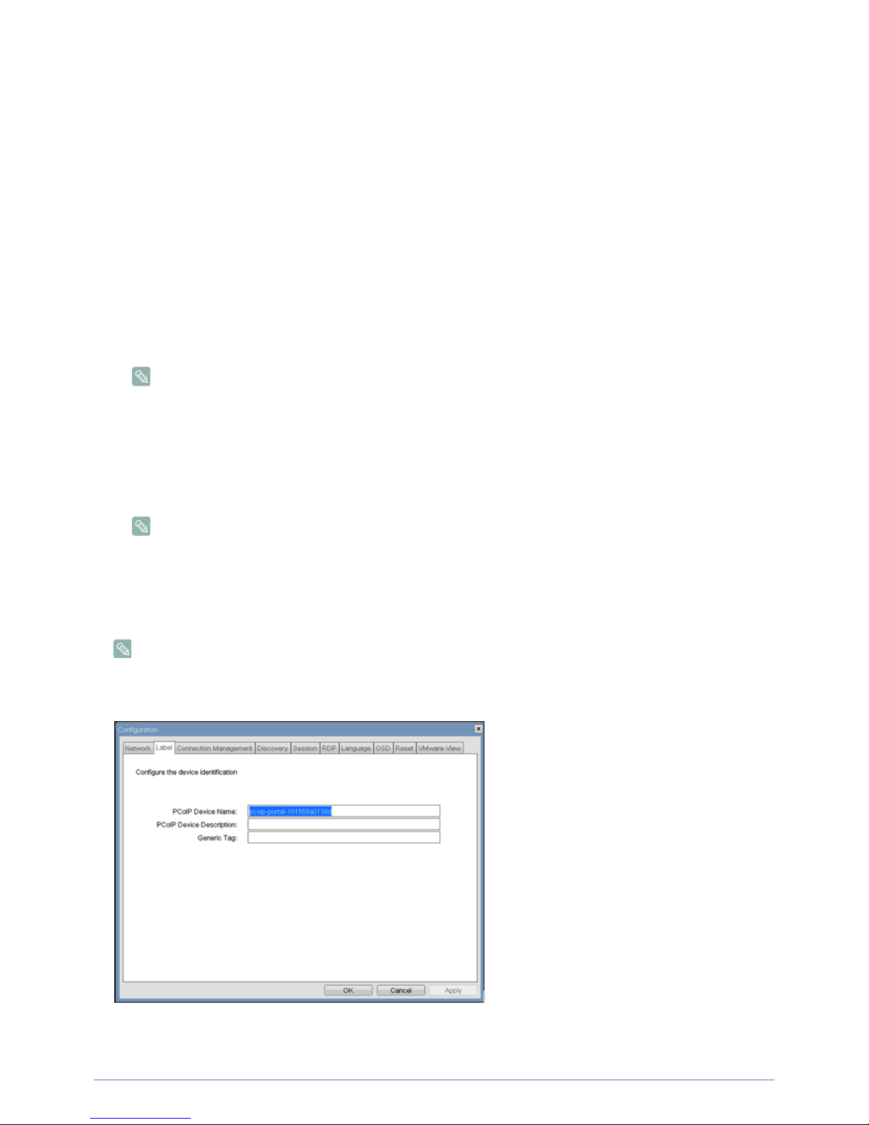
<Label> Tab
The <Label> tab allows an administrator to add custom information for the Host or Portal.
The Portal Label parameters can also be configured using the Webpage Administration Interface.
<Label> Configuration
• <PCoIP Device Name>
Figure 2-5:
Page 42
4-1 Installing the Software
If the <PCoIP Device Name> allows the administrator to give the Host or Portal a logical name. The default is pcoip-hostMAC or pcoip-portal-MAC where MAC is the Host or Portal’s MAC address.
• <PCoIP Device Description>
The <PCoIP Device Description> allows the administrator to give the Host or Portal a description or more information, e.g.
location of endpoint, etc.
The <PCoIP Device Description> is not used by the PCoIP Firmware and is provided strictly for administrator use.
• <Generic Tag>
The <Generic Tag> allows the administrator to give the Host or Portal a generic tag information.
The <Generic Tag> is not used by the PCoIP Firmware and is provided strictly for administrator use.
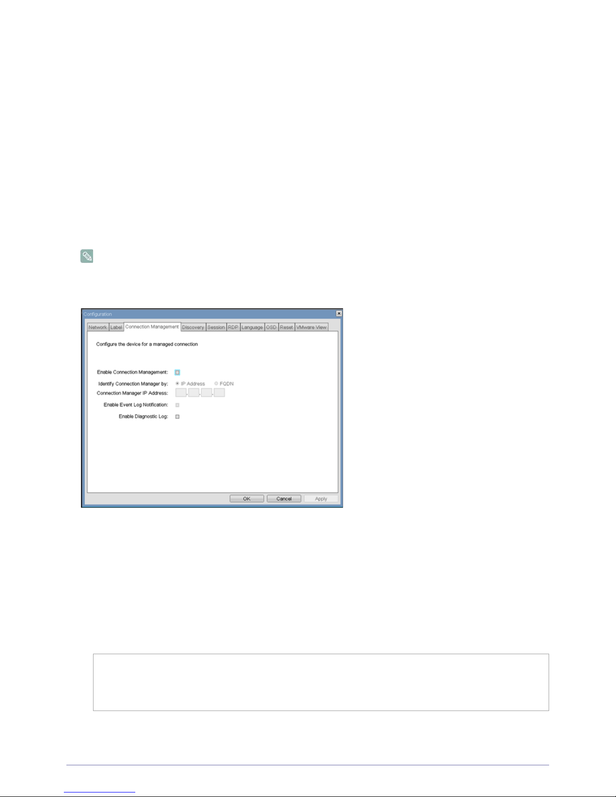
<Connection Management> Tab
The <Connection Management> tab allows enabling or disabling connection management, and to specify the IP address of
the connection manager.
In a managed connection, an external <Connection Managerment> Server communicates with and can remotely control and
configure the device. Additionally, the connection manager can locate an appropriate peer for the device to connect to and
initiate the connection. <Connection management> can greatly simplify the administration effort for a large, complex system.
The Connection Management parameters can also be configured using the Webpage Administration Interface.
Figure : <Connection Management> Configuration
• <Enable Connection Management>
If the <Enable Connection Management> option is enabled, the device can be configured and controlled by an external
connection manager.
• <Identify Connection Manager By>
The <Identify Connection Manager By> selector allows the administrator to choose whether the connection manager is
identified by <IP address> or by Fully Qualified Domain Name (FQDN). If connection management is disabled, this field is
not required and is not editable.
Table 2-1 shows the configuration parameters available when either method is chosen. If an invalid IP address or DNS
name is entered, the OSD will prompt the administrator to correct it.
Table 2-1: Connection Manager Method
• <Enable Event Log Notification>
The <Enable Event Log Notification> field controls whether the PCoIP Host and Portal devices send the contents of their
event logs to the connection management server.
METHOD DATA FIELDS
<IP address> Connection Manager IP Address
<FQDN> Connection Manager DNS name
2-6
Page 43
Installing the Software 4-1
• <Enable Diagnostic Log>
The <Enable Diagnostic Log> field controls whether connection management specific debug messages are written to the
event log of the PCoIP Host and Portal devices.
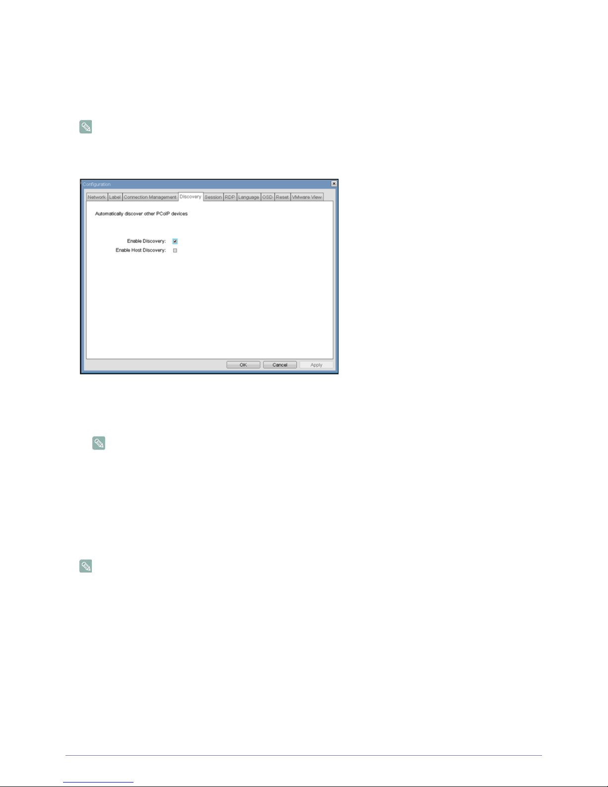
<Discovery> Tab
The <Discovery> configuration tab allows the use of features that ease the discovery of Portals in a PCoIP system.
The Discovery parameters can also be configured using the Webpage Administration Interface.
Figure : <Discovery> Configuration
• <Enable Discovery>
If the <Enable Discovery>option is enabled, the device will dynamically discover peer devices using SLP Discovery,
without requiring prior knowledge of their locations in the network. This can dramatically reduce configuration and
maintenance effort for complex systems.
SLP discovery requires routers configured to allow multicast, and therefore DNS-SRV Discovery is the
recommended discovery mechanism.
• <Enable Host Discovery>
The <Enable Host Discovery>feature allows the Portal to discover Hosts that are not in a PCoIP session.
When enabled, the Portal is able to display up to 10 available hosts in order of being discovered. It is expected that the
<Enable Host Discovery> feature will be used with small numbers of Hosts.
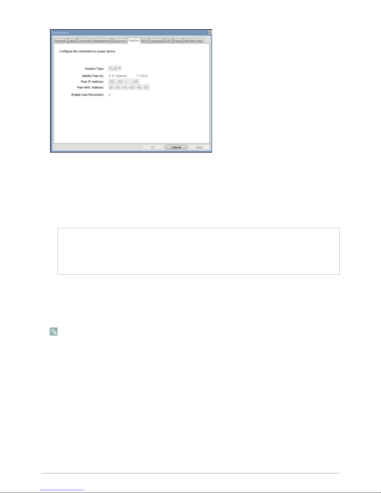
<Session> Tab
The <Session> tab allows an administrator to configure how the device connects to peer devices.
The Session parameters can also be configured using the Webpage Administration Interface.
Figure : <Session> Configuration
2-7
2-8
Page 44
4-1 Installing the Software
• <Session Type>
The <Session Type> allows the administrator to configure the Portal for a PCoIP session or RDP session.
• <Identify Peer By>
The <Identify Peer By> selector allows the administrator to choose whether the peer device is identified by IP and MAC
address or by Fully Qualified Domain Name (FQDN).
Table 2-2 shows the peer identity parameters available when either method is chosen. If an invalid IP address or DNS
name is entered, the OSD will prompt the administrator to correct it.
Table 2-2: Peer Identity Methods
• <Enable Auto-Reconnect>
The <Enable Auto-Reconnect> ption allows the Portal to automatically reconnect with the last connected Host when a
session is lost.
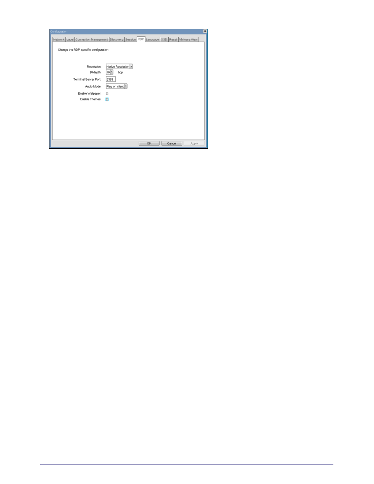
<RDP>
The <RDP> tab allows the administrator to configure settings specific to the Remote Desktop Protocol (<RDP>).
The RDP parameters can also be configured using the Webpage Administration Interface.
Figure : <RDP> Configuration
PEER IDENTITY METHOD DATA FIELDS COMMENT
Peer IP/MAC Peer IP Address PCoIP or Portal RDP client
Peer MAC Address PCoIP
Peer FQDN Peer FQDN PCoIP or Portal RDP client
2-9
Page 45
Installing the Software 4-1
<Resolution>
The <Resolution> field is the <RDP> screen resolution setting. Possible values are:
• <Native Resolution>
• <800x600>
• <1024x768>
• <1280x768>
• <1280x1024>
• <1440x900>
• <1600x1200>
• <1680x1050>
• <1920x1080>
• <1920x1200>
<Bit Depth>
The <Bit Depth> is the <RDP> session colour bit depth. Possible values are:
• <8 bpp>(bits per pixel)
• <16 bpp>
• <24 bpp>
<Terminal Server Port>
The <Terminal Server Port> field sets the port number that the <RDP> client connects to.
<Audio Mode>
The <Audio Mode> field configures where the audio playback occurs for the <RDP> session. Possible options are:
• <None>
• <Play on client>
• <Play on host>
<Enable Wallpaper>
The <Enable Wallpaper> field enables the use of wallpaper with the <RDP> session.
<Enable Themes>
The <Enable Themes> field enables the use of desktop themes with the <RDP> session.
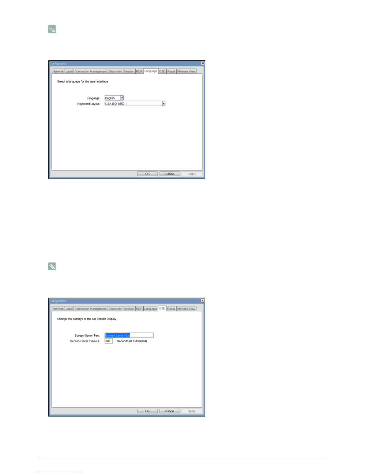
<Language> Tab
The <Language> field allows the administrator to configure the language of the OSD.
Page 46
4-1 Installing the Software
The Language parameters can also be configured using the Webpage Administration Interface.
Figure : <Language> Configuration
<Language>
The <Language> field allows configures the language of the OSD and user level event log messages.
<Keyboard Layout>
The <Keyboard Layout> field allows the administrator to change the keyboard layout.
<OSD> Tab
The <OSD> tab allows the administrator to modify the On Screen Display (<OSD>) parameters.
The OSD parameters can also be configured using the Webpage Administration Interface.
Figure : <OSD> Configuration
<Screen-Saver Message>
The <Screen-Saver Message> field allows the administrator to change the OSD screen-saver text. The text can be up to 240
2-10
2-11
Page 47
Installing the Software 4-1
characters.
The screen-screen saver is a simple black screen with the screen-saver text jumping randomly.
<Screen-Saver Timeout>
The <Screen-Saver Timeout> field allows the administrator to configure the screen-saver timeout. The timeout can be
configured in seconds, up to 9999 seconds. A setting of 0 seconds disables the screen-saver.
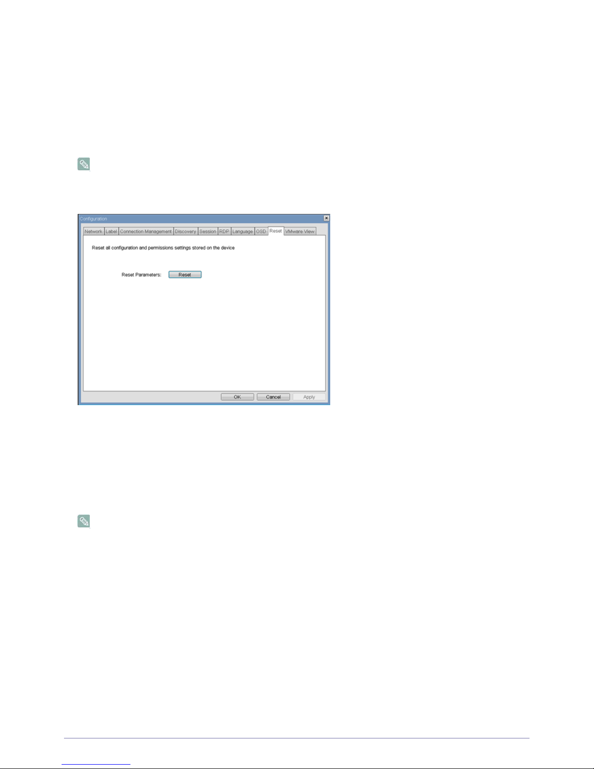
<Reset> Tab
The <Reset> tab allows the administrator to reset all the configurable parameters stored in flash.
The Reset can also be initiated using the Webpage Administration Interface.
Figure : <Reset>
<Reset Parameters>
The <Reset Parameters> <Reset> button resets all configuration and permissions to factory default values. When this button
is selected, the OSD will prompt the administrator for confirmation to prevent accidental resets.
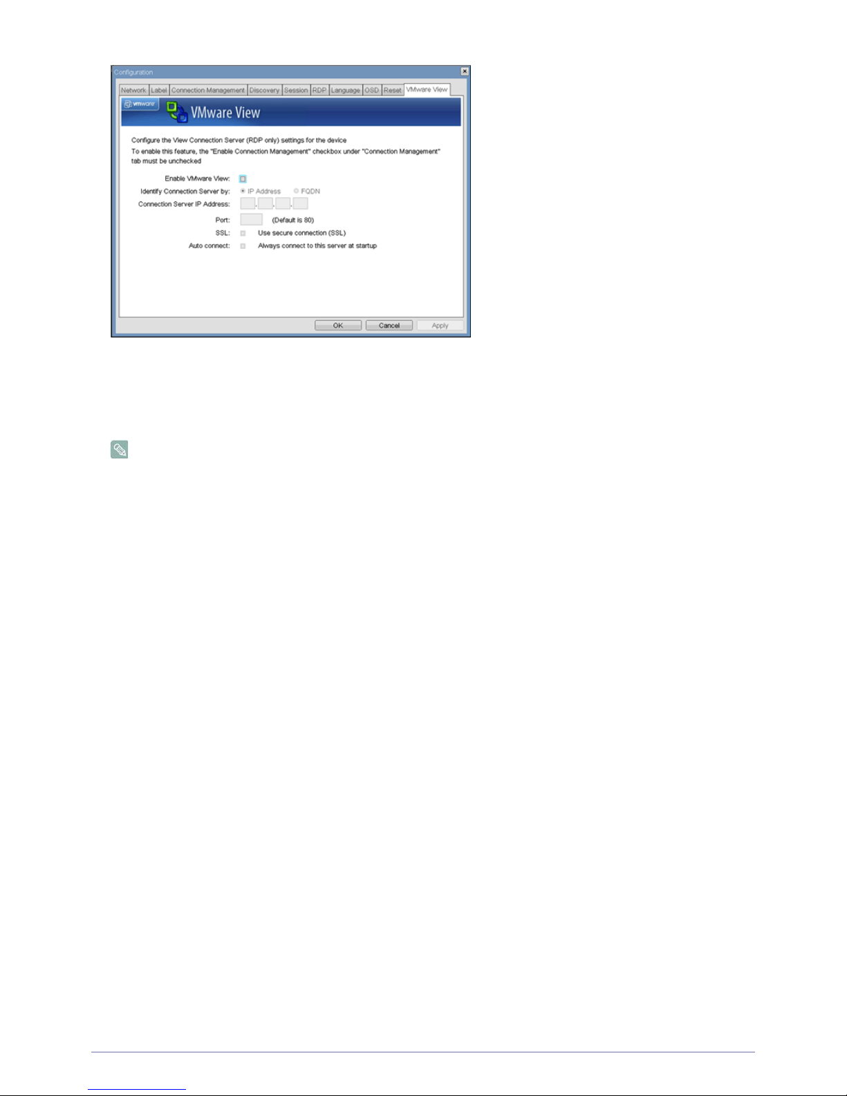
<VMware View> Tab
The <VMware View> tab allows configuration for use with a VMware View Connection Server.
The VMware View parameters can also be configured using the Webpage Administration Interface.
Figure : <VMware View> Configuration
2-12
2-13
Page 48
4-1 Installing the Software
<Enable VMware View>
When the <Enable VMware View> option is enabled, the Portals can be configured for use with a VMware View Connection
Server.
To enable the VMware View feature, the <Enable Connection Management> checkbox on the <Connection
Management> tab must be unchecked.
<Identify Connection Server by>
The <Identify Connection Server by> selector allows the administrator to choose whether the connection manager is identified
by IP address or by Fully Qualified Domain Name (FQDN). If VMware View is disabled, this field is not required and is not
editable.
<Port>
The <Port> parameter allows the administrator to specify the port used to communicate to the VMware View Connection
Server.
<SSL>
The <SSL> parameter allows the administrator to specify the <SSL> to communicate with the VMware View Connection
Server.
<Auto connect>
The <Auto connect> parameter allows the administrator to specify that the Portal automatically always connects with the
VMware View Connection Server at startup.
<Diagnostics> Window
The <Diagnostics> allows the administrator to access window tabs with diagnostics concerning the Portal. The tabs in the
<Diagnostics> window are:
• <Event Log>
• <Session Statistics>
• <PCoIP Processor>
•<Ping >
Each tab has a Close button to close the window.
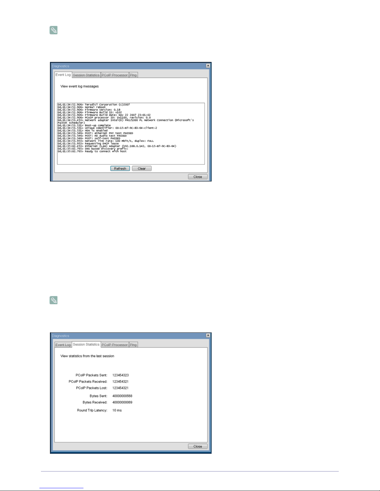
<Event Log> Tab
The <Event Log> tab allows the administrator to view and clear event log messages from the Portal.
Page 49
Installing the Software 4-1
The <Event Log> (terse or verbose) can also be initiated using the Webpage Administration Interface.
Figure : <Event Log>
<View event log message>
The <View event log messages> field displays log messages with time stamp information. There are two associated buttons
available.
•<Refresh>
Selecting the <Refresh> button refreshes the event log messages displayed.
• <Clear>
Selecting the <Clear> button clears all of the displayed event log messages.
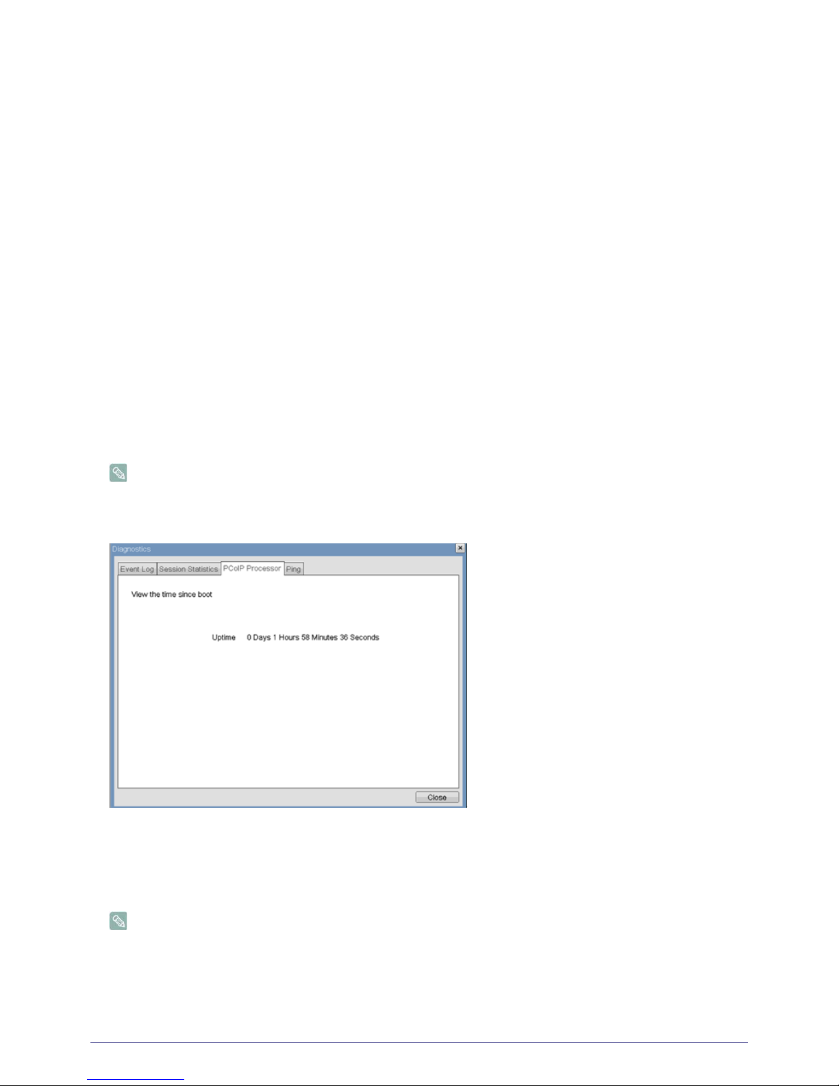
<Session Statistics> Tab
The <Session Statistics> tab allows the administrator to view PCoIP-specific statistics for the last PCoIP session that was
active on the Portal.
<Session Statistics> (terse or verbose) can also be viewed using the Webpage Administration Interface.
Figure : <Session Statistics>
2-14
2-15
Page 50
4-1 Installing the Software
<PCoIP Packets Statistics>
• <PCoIP Packets Sent>
The <PCoIP Packets Sent> field reports the total number of PCoIP packets sent from the Portal to the Host in the last
active session.
• <PCoIP Packets Received>
The <PCoIP Packets Received> ield reports the total number of PCoIP packets received from the Host to the Portal in the
last active session.
• <PCoIP Packets Lost>
The <PCoIP Packets Lost> field reports the total number of PCoIP packets lost in the last active session.
<Bytes Statistics>
• <Bytes Sent>
The <Bytes Sent >field reports the total number of bytes sent in the last active session.
• <Bytes Received>
The <Bytes Received> field reports the total number of bytes received in the last active session.
<
Round Trip Latency>
The <Round Trip Latency> field reports the total round-trip PCoIP system (e.g. Portal to Host and back to Portal) and network
latency in milliseconds (+/- 1 ms).
<PCoIP Processor> Tab
The <PCoIP Processor> tab allows the administrator to view the uptime of the Portal PCoIP processor since last boot.
The <PCoIP Processor> Uptime can also be viewed in the Webpage Administration Interface.
Figure : <PCoIP Processor>
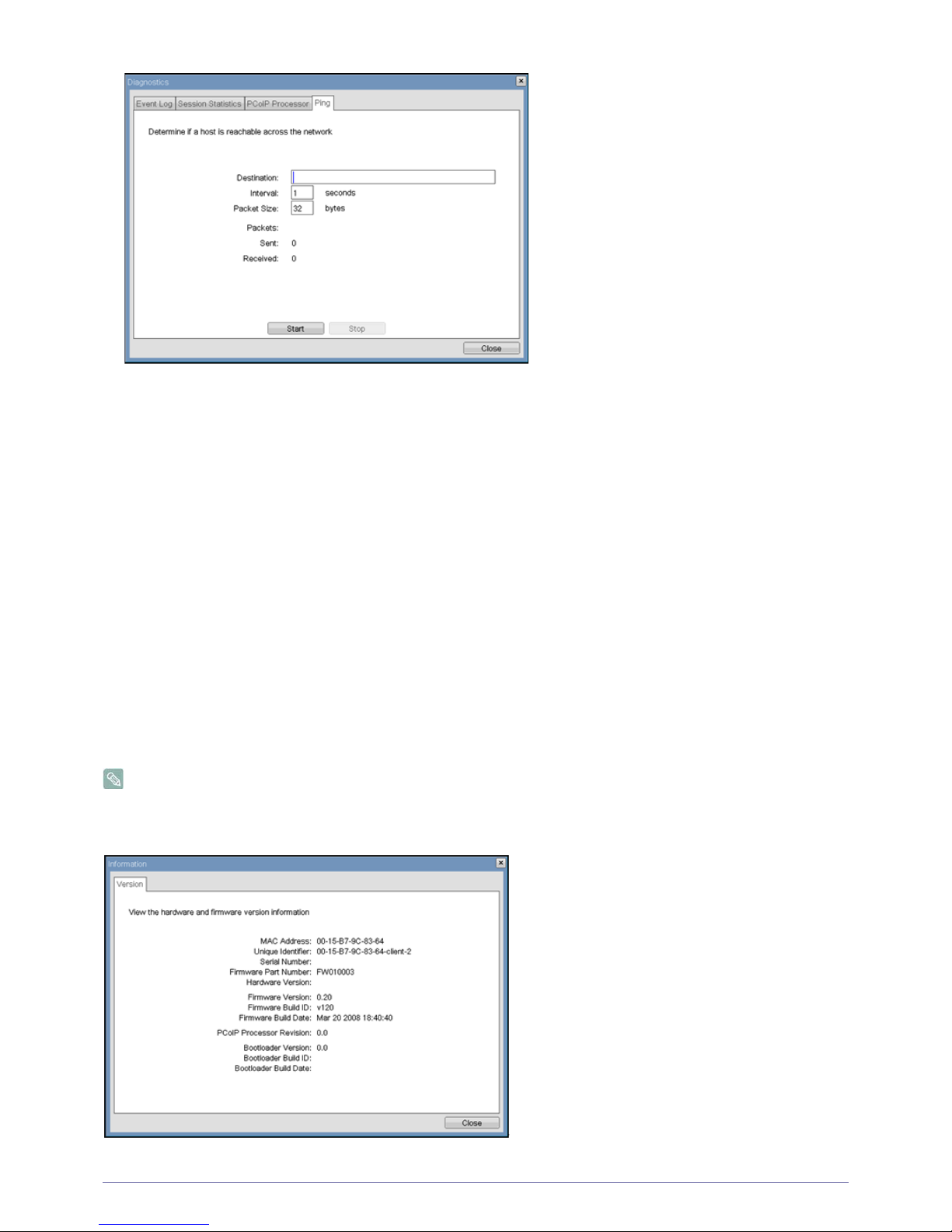
<Ping> Tab
The <Ping> tab allows the administrator to ping a device to see if it is reachable across an IP network. This may be useful for
determining if a Host is reachable.
The <Ping> tab has no matching menu in the Webpage Administration Interface of Section 1.
Figure : <Ping>
2-16
2-17
Page 51
Installing the Software 4-1
Ping Settings
• <Destination>
IP Address or FQDN to ping
• <Interval>
Interval between ping packets
• <Packet Size>
Size of ping packet
Packets
•<Sent>
Number of ping packets sent
• <Received>
Number of ping packets received
<Information> Window
The <Information> window allows an administrator to access the Version tab containing information about the device.
The Version information can also be viewed using the Webpage Administration Interface.
Figure : <Version>2-18
Page 52

4-1 Installing the Software
VPD Information
Vital Product Data (VPD) is information provisioned by the factory to uniquely identify each Portal or Host.
• <MAC Address>
Portal unique <MAC address>
• <Unique Identifier>
Portal unique identifier
•<Serial Number>
Portal unique serial number
• <Firmware Part Number>
Part number of PCoIP firmware
• <Hardware Version>
Portal hardware version number
Firmware Information
The <Firmware Information> reflects the current PCoIP firmware details.
• <Firmware Version>
Version of the current PCoIP firmware
• <Firmware Build ID>
Revision code of the current PCoIP firmware
• <Firmware Build Date>
Build date of the current PCoIP firmware
<PCoIP Processor Revision>
The <PCoIP Processor Revision> Revision field reports the PCoIP Processor Revision code. TERA1x00 Revision A silicon is
denoted by 0.0 and TERA1x00 Revision B silicon is denoted by 1.0.
Bootloader Information
The Bootloader information reflects the current PCoIP bootloader details.
• <Bootloader Version>
Version of the current PCoIP bootloader
• <Bootloader Build ID>
Revision code of the current PCoIP bootloader
• <Bootloader Build Date>
Build date of the current PCoIP bootloader
<User Settings> Window
The <User Settings> window allows the user to access window tabs that define the mouse and keyboard settings and the PCoIP
image quality.
The tabs in the User Settings menu are:
• <Mouse>
• <Keyboard>
• <Image>
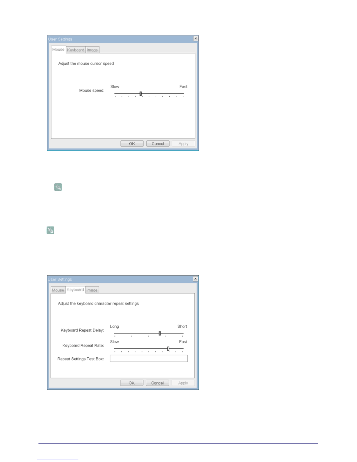
<Mouse> Tab
The <Mouse> tab allows a user to change the mouse cursor speed settings for the OSD and RDP sessions.
• The OSD mouse cursor speed setting does not affect the mouse cursor settings when a PCoIP session is active
unless the Local Keyboard Host Driver function is being used (see PCoIP Host Software User Guide for more
information).
•The <Mouse> tab has no corresponding menu in the Webpage Administration Interface of Section 1.
Page 53
Installing the Software 4-1
Figure : <Mouse>
• <Mouse Speed>
The <Mouse Speed> field allows the Portal mouse cursor speed to be configured.
The <Mouse Speed> can also be configured via the PCoIP Host Software. For more information on using the
PCoIP Host Software, refer to the PCoIP Host Software User Guide for more information.
<Keyboard> Tab
The <Keyboard> tab allows a user to change the keyboard repeat settings for the OSD and RDP sessions.
• The keyboard settings do not affect the keyboard settings when a PCoIP session is active unless the Local
Keyboard Host Driver function is being used (see PCoIP Host Software User Guide for more information).
•The <Keyboard> tab has no corresponding menu in the Webpage Administration Interface of Section 1.
Figure : <Keyboard>
• <Keyboard Repeat Delay >
The <Keyboard Repeat Delay> field allows a user to configure the Portal keyboard repeat delay.
• <Keyboard Repeat Rate>
The <Keyboard Repeat Rate> field allows a user to configure the Portal keyboard repeat rate.
2-19
2-20
Page 54
4-1 Installing the Software
• <Repeat Settings Test Box >
The <Repeat Settings Test Box> field allows a user to test the chosen keyboard settings.
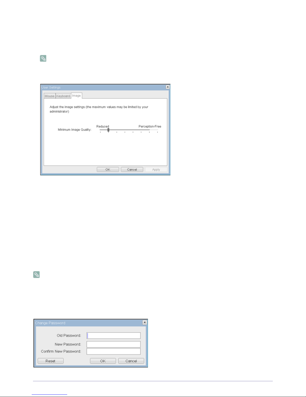
<Image>
The <Image> allows a user to change the image settings on the PCoIP system.
• The Image parameters can also be configured using the Webpage Administration Interface.
Figure : <Image>
• <Minimum Image Quality>
The <Minimal Image Quality> slider allows a user to make compromises between image quality and frame rate when
network bandwidth is limited. Some usage cases may require lower-quality images at a higher frame rate, while in other
cases higher-quality images at a lower frame rate may be preferred.
In environments where network bandwidth is constrained, moving the slider towards <Reduced> allows higher frame
rates; moving the slider towards <Perception-Free> allows higher image quality.
When network bandwidth is not constrained, the PCoIP system will maintain <perception-free> quality regardless of the
<Minimum Image Quality> setting.
<Password> Window
The <Password> window allows an administrator to update the administrative password for the device. Note that this will affect
the web interface and the local <OSD> GUI.
• Care must be taken when updating the Portal Password as the Portal may become unusable if the password is lost.
• The Password can also be updated using the Webpage Administration Interface.
• Some PCoIP devices have password protection disabled by default and this <Password> window is not available.
Password protection can be enabled through PCoIP Management Console for these devices.
Figure : <Change Password>
2-21
2-22
Page 55
Installing the Software 4-1
• <Old Password>
The <Old Password> field must match the current administrative password for the change to take place.
• <New Password>
The <New Password> field will be the new administrative password for both the web interface and the local OSD GUI.
• <Confirm New Password>
The <Confirm New Password> field must match the <New Password> field for the change to take place.
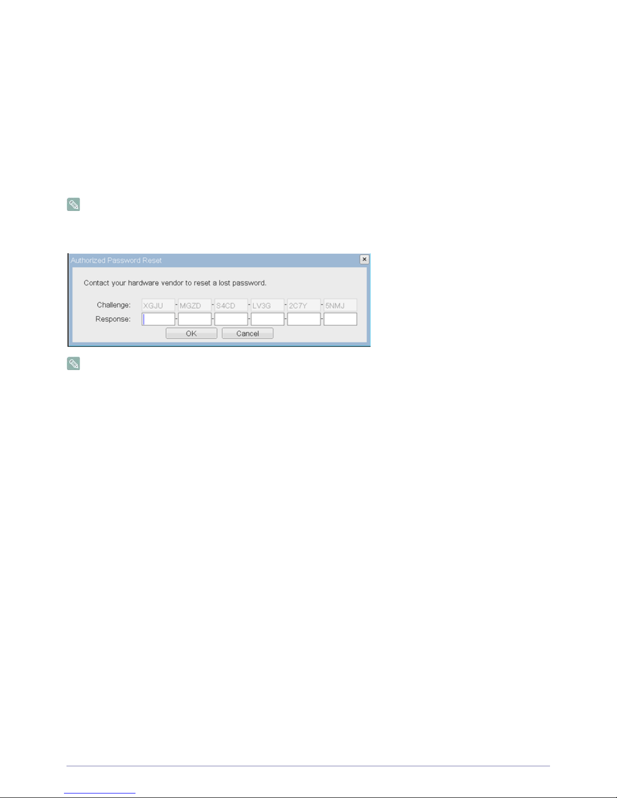
•<Reset>
In the unlikely event that a Portal password is lost, the <Reset> button allows an administrator to request a Response code
from their vendor. The Challenge code can be sent to the vendor. The vendor will qualify the request and return a Response
code if authorized.
Once the Response code is correctly entered, the Portal's password is reset to an empty string and the administrator is
prompted to enter a new password.
Contact the Portal vendor for more information when an authorized password reset is required.
Figure : <Authorized Password Reset>
Details on how to use PCoIP are subject to change. To view the latest information, visit the Teradici website.
(http://www.teradici.com)
2-23
Page 56

4-2 Installing the Software
4-2 Natural Color
What is Natural Color?
One of the problems with using a PC is that the colors you see on the screen are different from the colors of printed pictures or
source images input through a scanner or digital camera. Natural Color is a color management system developed by Samsung
Electronics to resolve this problem. This software works with Samsung products only and enables you to adjust the displayed
colors on the screen to match the colors of the printed pictures. For more information, refer to the online help of the software (F1).
The Natural Color is provided online. You can download it from the website below and install;
http://www.samsung.com/us/consumer/learningresources/monitor/naturalcolorexpert/pop_download.html
Page 57

Installing the Software 4-3
4-3 MagicTune
What is MagicTune?
MagicTune is a software program that helps with monitor adjustments by providing comprehensive descriptions of monitor
functions and easy-to-understand guidelines.
You can adjust the product with the mouse and the keyboard without using the operating buttons of the product.
Installing the Software
1. Insert the installation CD into the CD-ROM drive.
2. Select the MagicTune setup program.
If the pop-up screen for the software installation does not appear on the main screen, find and double-click the
MagicTune setup file on the CD-ROM.
3. Select the installation language and click [Next].
4. Complete the remaining software installation steps according to the instructions displayed on the screen.
• The software may not work properly if you do not restart the computer after the installation.
• The MagicTune icon may not appear depending on the computer system and the product specifications.
• If the shortcut icon does not appear, press the F5 key.
Restrictions and Problems with the Installation (MagicTune™)
The installation of MagicTune™may be affected by the graphics card, motherboard and the networking environment.
System Requirements
OS
• Windows 2000
• Windows XP Home Edition
• Windows XP Professional
• Windows Vista 32 Bit
• Windows 7 32 Bit
For MagicTune™, Windows 2000 or later is recommended.
Hardware
• At least 32 MB of memory
• At least 60 MB of free space on the hard disk drive
For more information, refer to the website.
Removing the Software
You can only remove MagicTune™through [Add or Remove Programs ] in Windows.
To remove MagicTune™, complete the following steps.
1. Click [Start] select [Settings], and select [Control Panel] from the menu.
For Windows XP, click [Start], and select [Control Panel] from the menu.
2. Double-click the [Add or Remove Programs] icon in the Control Panel.
Page 58

4-3 Installing the Software
3. In the [Add/Remove] window, find and select MagicTune™so that it is highlighted.
4. Click [Change or Remove Programs] to remove the software.
5. Select [Yes] to start removing MagicTune™.
6. Wait until a message box appears informing you that the software has been removed completely.
For technical support, the FAQ (frequently asked questions) or information about the software upgrade for MagicTune™,
please visit our website.
Page 59

Installing the Software 4-4
4-4 MultiScreen
What is MultiScreen ?
MultiScreen enables users to use the monitor by partitioning multiple sections.
Installing the Software
1. Insert the installation CD into the CD-ROM drive.
2. Select the MultiScreen setup program.
If the pop-up screen for the software installation does not appear on the main screen, find and double-click the
MultiScreen setup file on the CD-ROM.
3. When the Installation Wizard appears, click [Next].
4. Complete the remaining software installation steps according to the instructions displayed on the screen.
The software may not work properly if you do not restart the computer after the installation.
The MultiScreen icon may not appear depending on the computer system and the product specifications.
If the shortcut icon does not appear, press the F5 key.
Restrictions and Problems with the Installation (MultiScreen)
The MultiScreen installation may be affected by the graphics card, motherboard and the networking environment.
Operating System
OS
• Windows 2000
• Windows XP Home Edition
• Windows XP Professional
• Windows Vista 32 Bit
• Windows 7 32 Bit
For MultiScreen, the operating systems Windows 2000 or later is recommended.
Hardware
• At least 32 MB of memory
• At least 60 MB of free space on the hard disk drive
Removing the Software
Click [Start], select [Settings]/[Control Panel], and then double-click [Add or Remove Programs].
Select MultiScreen from the program list and click the [Add/Delete] button.
Page 60

4-4 Installing the Software
Page 61
Troubleshooting 5-1
5 Troubleshooting
5-1 Monitor Self-Diagnosis
• You can check if the product is working properly using the Self-Diagnosis function.
• If a blank screen is displayed and the Power LED blinks even if the product and the PC are properly connected, perform
the self-diagnosis function according to the procedures below.
1. Turn the product and the PC off.
2. Separate the signal cable from the product .
3. Turn the product on.
4. If the product is working properly, the <Check Signal Cable> message appears.
In this case, if a blank screen is displayed again, make sure that there is no problem with the PC and the connection. The product
is working properly.
5-2 Before Requesting Service
Please check the following before requesting After-Sales service. If the problem continues, please contact your nearest
Samsung Electronics Service Center.
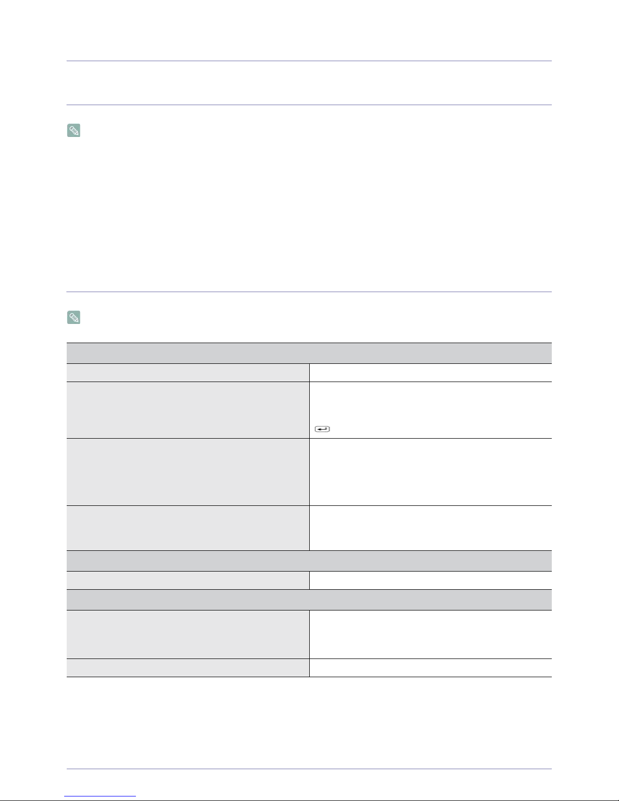
A blank screen appears / I cannot turn the product on
Is the power cord connected properly? Check the connection status of the power cord.
Is the <Check Signal Cable> message displayed on the
screen?
Check the cable connecting the PC and the product.
If the message appears on the screen even if the cable is
properly connected, recheck the input signal by pressing the
/SOURCE button of the product.
Is the <Not Optimum Mode> message displayed on the
screen?
This occurs when the signal from the graphics card exceeds
the maximum resolution or the maximum frequency of the
product.
In this case, set up the appropriate resolution and the frequency for the product.
Is a blank screen displayed and does the power LED blink at
a 1 second interval?
This occurs when the power saving function is running.
If you click the mouse or press any key, the screen will be
turned on.
The buttons on the monitor are not functioning.
Is the key lock mode enabled? Disable the key lock mode if it is enabled.
The color is weird / The picture is displayed in black and white
Is the entire screen displayed in the same color as if viewing
the screen through a cellophane paper?
Check the cable connection to the computer.
Reinsert the graphics card into the computer completely.
Check if the <Color Effect> is set to <Off>.
Is the graphics card configured correctly? Set up the graphics card referring to the user manual.
Page 62
5-2 Troubleshooting
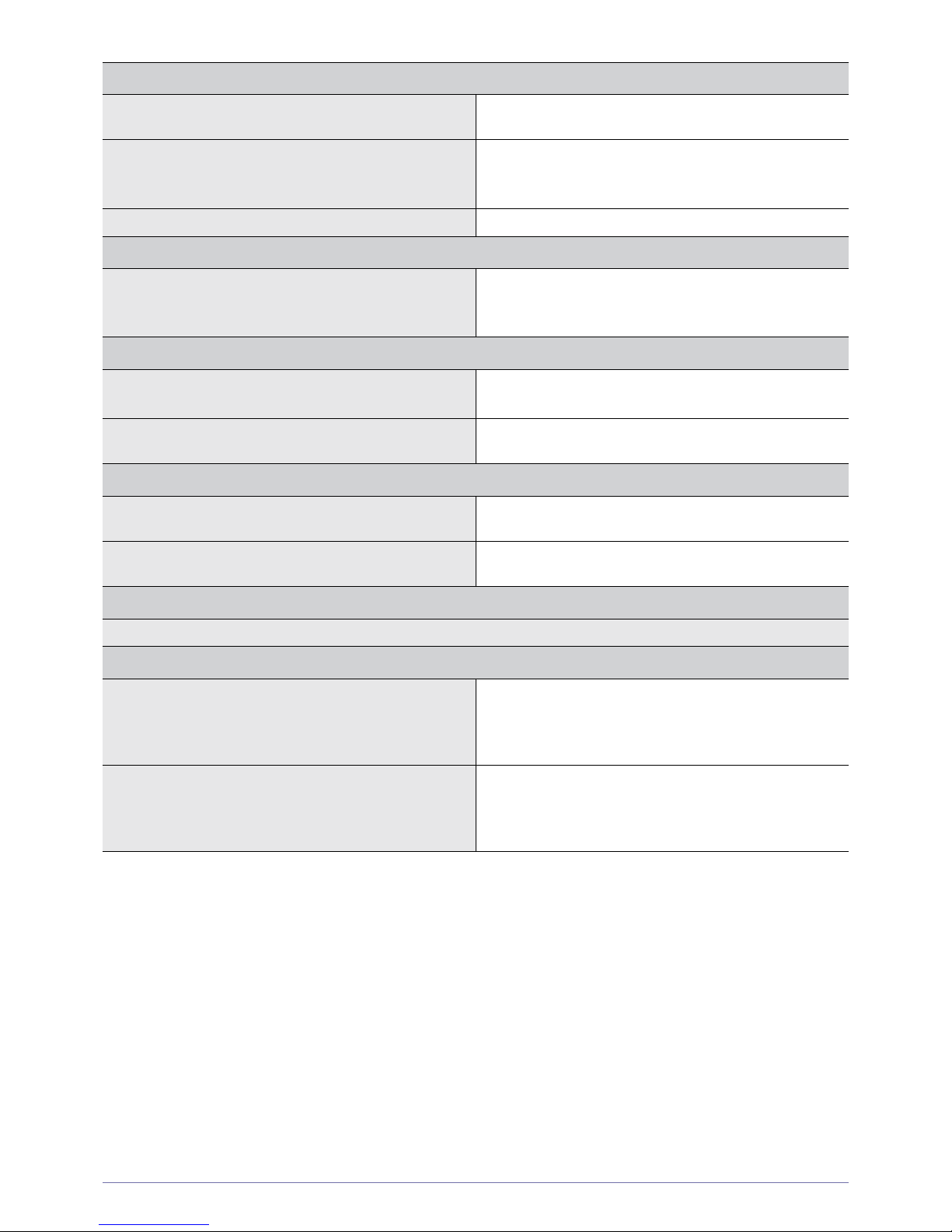
The display area suddenly moves to an edge or to the center.
Did you change the graphics card or the driver? Please press the [AUTO] button to run the auto adjustment
function.
Did you change the resolution and frequency appropriate to
the product?
Set the resolution and the frequency to the appropriate values
in the graphics card
Refer to the (Standard Signal Mode Table)
Is the graphics card configured correctly? Set up the graphics card referring to the user manual.
The pictures are out-of-focus.
Did you change the resolution and the frequency appropriate
to the product?
Set the resolution and the frequency to the appropriate values
in the graphics card
Refer to the (Standard Signal Mode Table)
The color is displayed in 16 bit (16 colors). The color has been changed after changing the graphics card.
Did you install the device driver for the product? Windows ME/XP/2000 : Set the color again by selecting Con-
trol Panel → Display → Settings.
Is the graphics card configured correctly? Configure the color again in accordance with the new graph-
ics card driver.
When I connect the monitor, the 'Unknown monitor, Plug&Play (VESA DDC) monitor found' message is displayed.
Did you install the device driver for the product? Install the device driver referring to the descriptions about the
driver installation.
Check if all the Plug&Play (VESA DDC) functions are supported referring to the User Manual of the graphics card.
Install the device driver referring to the descriptions about the
driver installation.
A “beep, beep” sound is heard when booting the computer.
If the beep sound is generated 3 or more times when booting up the computer, please request service for the computer.
Problems related to Audio
No sound Ensure that the audio cable is firmly connected to both the
audio-in port on your monitor and the audio-out port on your
sound card.
Check the volume level.
Sound level is too low. Check the volume level.
If the volume is still too low after turning the control to its maximum, check the volume control on the computer sound card
or software program.
Page 63
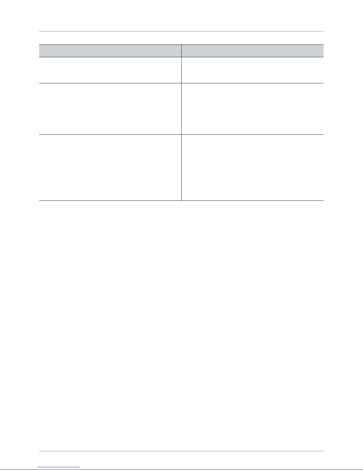
Troubleshooting 5-3
5-3 FAQ
FAQ! Please try the following!
How can I change the frequency of the video signal? You have to change the frequency of the graphics card.
(For more information, refer to the User Manual of the computer or the graphics card).
How can I change the resolution? Windows XP : Change the resolution by selecting Control
Panel
→ Appearance and Themes → Display → Settings.
Windows ME/2000 : Change the resolution by selecting Con-
trol Panel
→ Display → Settings.
(For more information, refer to the User Manual of the computer or the graphics card).
How can I use the power saving function?
Windows XP : Configure it by selecting Control Panel
→
Appearance and Themes
→ Display → Screen Saver Set-
ting or configure it in the BIOS Setup of the computer.
Windows ME/2000 : Configure it by selecting Control Panel
→ Display → Screen Saver Setting or Configure it in the
BIOS Setup of the computer.
For more information, refer to the Windows user manual for
the computer.
Page 64
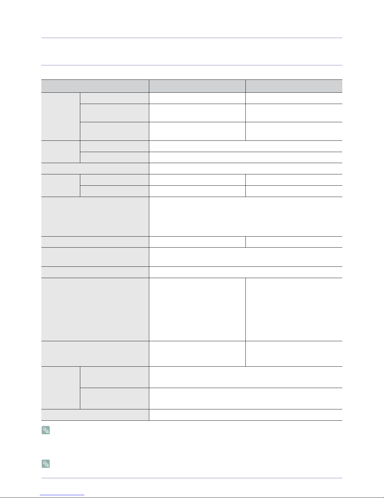
6-1 More Information
6 More Information
6-1 Specifications
Class B (Information Communication equipment for residential use)
This device is registered for EMC requirements for home use (Class B). It can be used in all areas.
(Class B equipment emits less electromagnetic waves than Class A equipment).
Design and specifications are subject to change without prior notice.
MODEL NAME NC190 NC240
LCD Panel Size 19 inches (48 cm) 23.6 inches (59 cm)
Display area 376.32 mm (H) x 301.1 mm (V) / 14.8
inches (H) x 11.9 inches (V)
521.28 mm (H) x 293.22 mm (V) / 20.5
inches (H) x 11.5 inches (V)
Pixel Pitch 0.294 mm (H) 0.294 mm (V) / 0.012
inches (H) x 0.012 inches (V)
0.2715 mm (H) x 0.2715 mm (V) /
0.0107 inches (H) x 0.0107 inches (V)
Synchronization
Horizontal 30 ~ 81 kHz
Vertical 56 ~ 75 Hz
Display Color 16.7 M
Resolution Optimum resolution 1280 x 1024 @ 60 Hz 1920 x 1080 @ 60 Hz (RB)
Maximum resolution 1280 x 1024 @ 75 Hz 1920 x 1080 @ 60 Hz (RB)
Input Signal, Terminated
RGB Analog
0.7 Vp-p ± 5 %
Separate H/V sync, Composite
TTL Level (V high ≥ 2.0 V, V low ≤ 0.8 V)
Maximum Pixel Clock 135 MHz 170 MHz (Analog, Digital)
Power Supply This product supports 100 – 240 V. Since the standard voltage may differ from
country to country, please check the label on the back of the product.
Signal connectors
15pin D-sub connector
Dimensions (WxHxD) / Weight 410.7 x 344.4 x 74.0 mm / 16.2 x 13.6
x 2.9 inches (Without Stand)
410.7 x 385.6 x 197.0 mm / 16.2 x 15.2
x 7.8 inches (With Stand), 6.2kg / 13.7
Ibs
568.6 x 77.7 x 341.9 mm / 22.4 x 3.1 x
13.5 inches (Without Stand) 6.25 kg /
13.8 Ibs(with Speaker), 6.05 kg / 13.3
Ibs (without Speaker)
568.6 x 226.0 x 385.2 mm / 22.4 x 8.9
x 15.2 inches (With Stand) 8.65 kg /
19.1 Ibs (with Speaker), 8.45 kg / 18.6
Ibs (without Speaker)
VESA Mounting Interface
100 mm x 100 mm
/
3.9 inches x 3.9
inches
200
mm
x 100 mm /
7.9 inches x 3.9
inches
/
100 x 100 mm
/
3.9 inches x 3.9
inches
Environmental considerations
Operating
Temperature : 50 °F ~ 104 °F (10 °C ~ 40 °C)
Humidity :10 % ~ 80 %, non-condensing
Storage
Temperature : -4 °F ~ 113 °F (-20 °C ~ 45 °C)
Humidity : 5 % ~ 95 %, non-condensing
Tilt 0 ° ~ 20 °
Page 65

More Information 6-1
(USA ONLY)
Dispose unwanted electronics through an approved recycler.
To find the nearest recycling location, go to our website,
www.samsung.com/recyclingdirect, or call (877) 278 - 0799
Page 66
6-2 More Information
6-2 Power Saving Function
This product provides a power saving function that automatically turns the screen off when the product is not used for a
predetermined period of time to reduce power consumption. If the product enters power saving mode, the power LED turns to a
different color to indicate that the product is in power saving mode.
When the product is in power saving mode, the power is not turned off and you can turn the screen on again by pressing any key
or clicking the mouse. However, the power saving function only works when the product is connected to a computer that provides
the power saving function.
If there is no power cut-off switch, the power consumption is "0" only when the power cord is disconnected.
STATE NORMAL OPERATION
POWER OFF
(STAND BY)
POWER OFF
(MECHANICAL SWITCH
OFF)
Power Indicator On Off Off
Power Consumption NC190 : 37 watts Less than
2.7 watts
0 watts
NC240 : 67 watts
Page 67
More Information 6-3
6-3 Contact SAMSUNG WORLDWIDE
If you have any questions or comments relating to Samsung products, please contact the SAMSUNG customer care center.
NORTH AMERICA
U.S.A 1-800-SAMSUNG (726-7864) http://www.samsung.com
CANADA 1-800-SAMSUNG (726-7864) http://www.samsung.com/ca
http://www.samsung.com/ca_fr (French)
MEXICO 01-800-SAMSUNG (726-7864) http://www.samsung.com
LATIN AMERICA
ARGENTINA 0800-333-3733 http://www.samsung.com
BRAZIL 0800-124-421
4004-0000
http://www.samsung.com
BOLIVIA 800-10-7260 http://www.samsung.com
CHILE 800-SAMSUNG (726-7864)
From mobile 02-482 82 00
http://www.samsung.com
COLOMBIA 01-8000112112 http://www.samsung.com
COSTA RICA 0-800-507-7267 http://www.samsung.com
DOMINICA 1-800-751-2676 http://www.samsung.com
ECUADOR 1-800-10-7267 http://www.samsung.com
EL SALVADOR 800-6225 http://www.samsung.com
GUATEMALA 1-800-299-0013 http://www.samsung.com
HONDURAS
800-27919267
http://www.samsung.com
JAMAICA 1-800-234-7267 http://www.samsung.com
NICARAGUA 00-1800-5077267 http://www.samsung.com
PANAMA 800-7267 http://www.samsung.com
PERU 0-800-777-08 http://www.samsung.com
PUERTO RICO 1-800-682-3180 http://www.samsung.com
TRINIDAD & TOBAGO 1-800-SAMSUNG (726-7864) http://www.samsung.com
VENEZUELA 0-800-100-5303 http://www.samsung.com
EUROPE
ALBANIA 42 27 5755 http://www.samsung.com
AUSTRIA 0810 - SAMSUNG
(7267864,€ 0.07/min)
http://www.samsung.com
BELGIUM 02-201-24-18 http://www.samsung.com/be (Dutch)
http://www.samsung.com/be_fr
(French)
BOSNIA 05 133 1999 http://www.samsung.com
BULGARIA 07001 33 11 http://www.samsung.com
CROATIA 062 SAMSUNG (062 726 7864) http://www.samsung.com
Page 68
6-3 More Information
CZECH 800 - SAMSUNG (800-726786) http://www.samsung.com
Samsung Electronics Czech and Slovak, s.r.o.,
Oasis Florenc, Sokolovská 394/17, 180 00, Praha 8
DENMARK 70 70 19 70 http://www.samsung.com
FINLAND 030 - 6227 515 http://www.samsung.com
FRANCE 01 48 63 00 00 http://www.samsung.com
GERMANY 01805 - SAMSUNG
(726-7864,€ 0,14/Min)
http://www.samsung.com
CYPRUS From landline : 8009 4000 http://www.samsung.com
GREECE From landline : 80111-
SAMSUNG (7267864)
From landline & mobile : (+30)
210 6897691
http://www.samsung.com
HUNGARY 06-80-SAMSUNG (726-7864) http://www.samsung.com
ITALIA 800-SAMSUNG (726-7864) http://www.samsung.com
KOSOVO +381 0113216899 http://www.samsung.com
LUXEMBURG 261 03 710 http://www.samsung.com
MACEDONIA 023 207 777 http://www.samsung.com
MONTENEGRO 020 405 888 http://www.samsung.com
NETHERLANDS 0900 - SAMSUNG (0900-7267864)
(€ 0,10/Min)
http://www.samsung.com
NORWAY 815-56 480 http://www.samsung.com
POLAND 0 801-1SAMSUNG (172-678)
+48 22 607-93-33
http://www.samsung.com
PORTUGAL 808 20 - SAMSUNG (808 20 7267) http://www.samsung.com
RUMANIA From landline : 08010- SAMSUNG
(7267864)
From landline & mobile : (+40)
21 206 01 10
http://www.samsung.com
SERBIA 0700 Samsung (0700 726 7864) http://www.samsung.com
SLOVAKIA 0800 - SAMSUNG(0800-726 786) http://www.samsung.com
SPAIN 902 - 1 - SAMSUNG (902 172 678) http://www.samsung.com
SWEDEN 0771 726 7864 (SAMSUNG) http://www.samsung.com
SWITZERLAND 0848-SAMSUNG
(7267864, CHF 0.08/min)
http://www.samsung.com/ch
http://www.samsung.com/ch_fr (French)
U.K 0330 SAMSUNG (7267864) http://www.samsung.com
EIRE 0818 717100 http://www.samsung.com
LITHUANIA 8-800-77777 http://www.samsung.com
LATVIA 8000-7267 http://www.samsung.com
ESTONIA 800-7267 http://www.samsung.com
TURKEY 444 77 11 http://www.samsung.com
EUROPE
Page 69
More Information 6-3
CIS
RUSSIA 8-800-555-55-55 http://www.samsung.com
GEORGIA 8-800-555-555 http://www.samsung.com
ARMENIA 0-800-05-555 http://www.samsung.com
AZERBAIJAN 088-55-55-555 http://www.samsung.com
KAZAKHSTAN 8-10-800-500-55-500
(GSM: 7799)
http://www.samsung.com
UZBEKISTAN 8-10-800-500-55-500 http://www.samsung.com
KYRGYZSTAN 00-800-500-55-500 http://www.samsung.com
TADJIKISTAN 8-10-800-500-55-500 http://www.samsung.com
MONGOLIA http://www.samsung.com
UKRAINE 0-800-502-000 http://www.samsung.com/ua
http://www.samsung.com/ua_ru
BELARUS 810-800-500-55-500 http://www.samsung.com
MOLDOVA 00-800-500-55-500 http://www.samsung.com
ASIA PACIFIC
AUSTRALIA 1300 362 603 http://www.samsung.com
NEW ZEALAND 0800 SAMSUNG (0800 726 786) http://www.samsung.com
CHINA 400-810-5858 http://www.samsung.com
HONG KONG
(852) 3698 - 4698
http://www.samsung.com/hk
http://www.samsung.com/hk_en/
INDIA 1800 1100 11
3030 8282
1800 3000 8282
1800 266 8282
http://www.samsung.com
INDONESIA 0800-112-8888
021-5699-7777
http://www.samsung.com
JAPAN 0120-327-527 http://www.samsung.com
MALAYSIA 1800-88-9999 http://www.samsung.com
PHILIPPINES 1-800-10-SAMSUNG
(726-7864) for PLDT
1-800-3-SAMSUNG(726-7864)
for Digitel
1-800-8-SAMSUNG(726-7864)
for Globe
02-5805777
http://www.samsung.com
SINGAPORE 1800-SAMSUNG (726-7864) http://www.samsung.com
THAILAND 1800-29-3232
02-689-3232
http://www.samsung.com
TAIWAN 0800-329-999
0266-026-066
http://www.samsung.com
VIETNAM 1 800 588 889 http://www.samsung.com
Page 70
6-3 More Information
MIDDLE EAST
IRAN 021-8255 http://www.samsung.com
OMAN 800-SAMSUNG (726-7864) http://www.samsung.com
KUWAIT 183-2255 http://www.samsung.com
BAHRAIN 8000-4726 http://www.samsung.com
EGYPT 08000-726786 http://www.samsung.com
JORDAN 800-22273 http://www.samsung.com
MOROCCO 080 100 2255 http://www.samsung.com
SAUDI ARABIA 9200-21230 http://www.samsung.com
U.A.E 800-SAMSUNG (726-7864) http://www.samsung.com
AFRICA
CAMEROON 7095- 0077 http://www.samsung.com
COTE D’ IVOIRE 8000 0077 http://www.samsung.com
GHANA 0800-10077
0302-200077
http://www.samsung.com
KENYA 0800 724 000 http://www.samsung.com
NIGERIA 0800-726-7864 http://www.samsung.com
SENEGAL 800-00-0077 http://www.samsung.com
SOUTH AFRICA 0860-SAMSUNG (726-7864) http://www.samsung.com
TANZANIA 0685 88 99 00 http://www.samsung.com
UGANDA 0800 300 300 http://www.samsung.com
Page 71

More Information 6-4
6-4 Correct Disposal of This Product
(Waste Electrical & Electronic Equipment)
(Applicable in the European Union and other European countries with separate collection systems)
This marking on the product, accessories or literature indicates that the product and its electronic accessories (e.g.
charger, headset, USB cable) should not be disposed of with other household waste at the end of their working
life. To prevent possible harm to the environment or human health from uncontrolled waste disposal, please separate these items from other types of waste and recycle them responsibly to promote the sustainable reuse of material resources.
Household users should contact either the retailer where they purchased this product, or their local government
office, for details of where and how they can take these items for environmentally safe recycling.
Business users should contact their supplier and check the terms and conditions of the purchase contract. This
product and its electronic accessories should not be mixed with other commercial wastes for disposal.
 Loading...