

Page 1
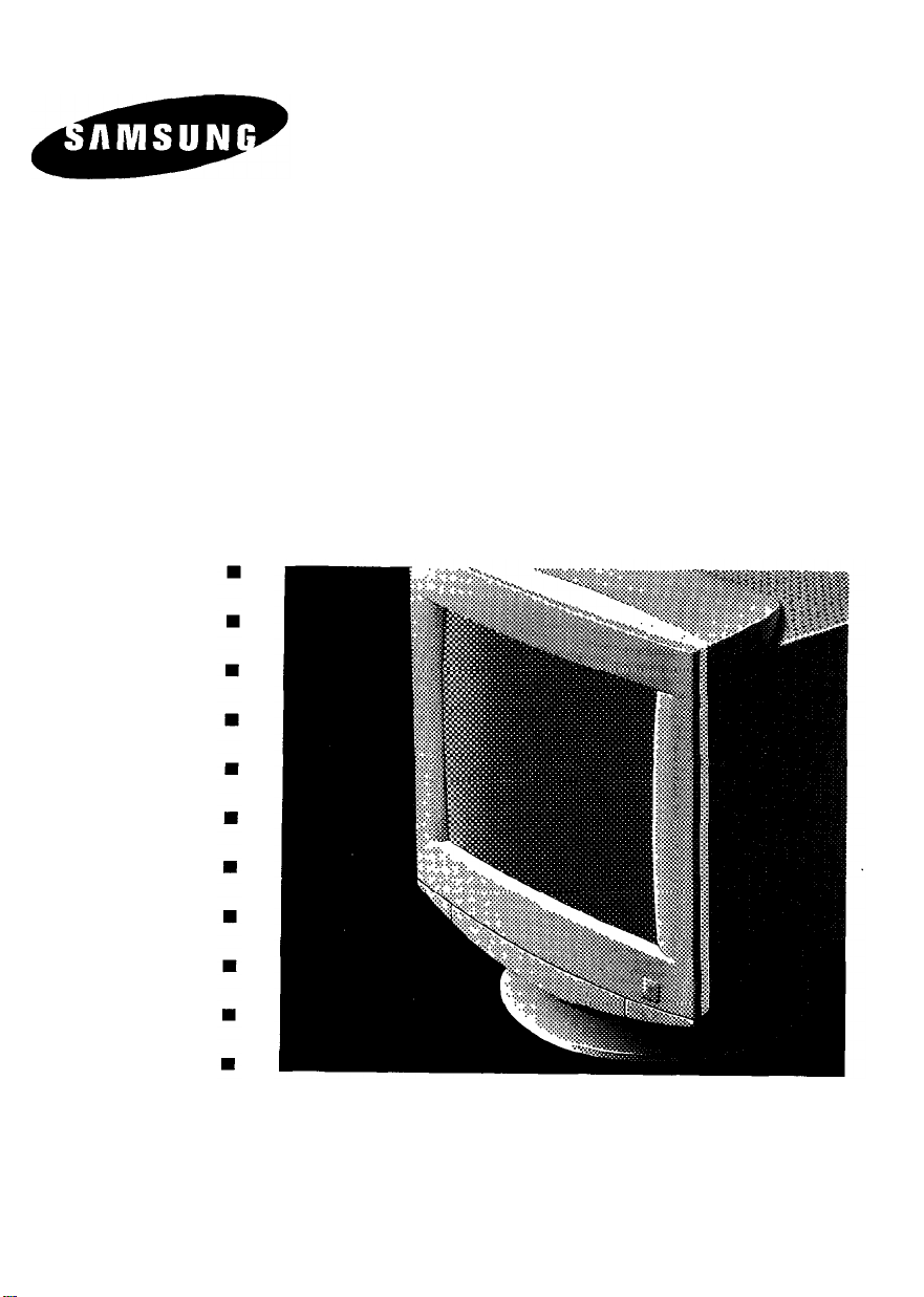
SyncMaster 15GLe
38 Cm ( 15” Diagonal )
Basic : CMA5377L
User’s Manual
n
n
n
n
n
n
n
n
n
n
n
n
n
n
n
n
n
n
n
n
n
n
n
n
n
n
n
n
n
n
n
n
n
n
n
n
n
n
n
n
n
n
n
n
COLOR DISPLAY UNIT
Page 2

Contents of Your Package
The SyncMaster 15GLe is a delicate, precision instrument.
Be sure that you can comfortably lift the monitor from its
package, and that you have a sturdy and stable work surface
that can support the monitor.
After removing the SyncMaster 15GLe from its packing,
make sure you have everything you need to set up your
system.
Unpack all components and match them against the following packing list:
1 Samsung SyncMaster 15GLe Color Monitor
1 Tilt and Swivel Stand
1 Support stand
1 Power Cord
1 Signal Cable
1 User’s Manual
1 Warranty Registration Card (Optional )
If you are missing any of these items, contact your Samsung
dealer.
Note
: Samsung recommends saving your SyncMaster
15GLe Color Monitor box and its packing materials. Use only
the original packaging for shipment or relocation of your
monitor. Subsitute packaging may not provide adequate protection.
*MPR // Compliance: SyncMaster 15GLe comply with
SWEDAC ( MPR II ) recommendations for reduced electric
and
magnetic fields.
Table of Contents
Introduction
About This Manual
Features of Your Monitor
Safety Tips
Installation
Connection to Your Computer
IBM or PC-Compatible
Macintosh
Controls and Adjustments
Controls and Their Locations
Basic Controls and LED
Indicator Functions
Microprocessor Controls
and Functions
Control Function Buttons
Display Adjustment Buttons
Technical Control Functions
Power Management System
Adjustment Examples
Troubleshooting
Troubleshooting Chart
Appendix
Specifications
FCC Information
IC Compliance Notice
Pin Assignments
Factory Modes Timing Signal Chart
2
3
4
5
6
9
9
9
9
10
10
11
12
14
15
16
17
17
18
Note:
l
SyncMaster is a registered trademark of Samsung
Electronics, Co.. Ltd.
l
IBM, VGA, XGA, XGA II and PS/2 are registered trademarks of International Business Machines Corporation.
l
Apple and Macintosh are registered trademarks of Apple
Computer, Inc. Macintosh Centris and Macintosh Quadra
are trademarks of Apple Computer, Inc.
l
Super-VGA ( SVGA ) and VESA are registered trademarks
of the Video Electronics Standards Association.
Page 3
Green Series Monitor:
one of Samsung’s Green Series family of
monitors. As such, it offers you new
opportunities to cut power consumption,
recycle materials and reduce the risk of
health hazards.
This product is
ongratulations on your
purchase of the Samsung
SyncMaster 15GLe Color
Monitor! Your SyncMaster is a
38 cm ( 15” ), high-resolution
( 1024 x 768 ) color monitor
that offers many outstanding
high performance features
( see page 3 ).
Samsung stands for quality:
is one of the world’s largest manufactur-
ers of quality monitors. At Samsung, quality control starts by checking and testing
every component that goes into a
SyncMaster monitor. Then, every monitor
undergoes rigorous performance testing.
This meticulous attention to detail has
been recognized by the International
Organization for Standards, which conferred its prestigious ISO certification to
Samsung for product quality.
For you, the end user, Samsung’s quality
means reliability. You are assured that
your SyncMaster monitor will deliver crisp,
high-resolution images and trouble-free
performance, day after day, year after
year.
Samsung stands for technology:
SyncMaster monitor meets stringent international ergonomic standards for low radiation. The monitor is designed to satisfy
the most demanding “safe-workplace”
requirements by meeting the strict
Swedish MPR II guidelines for lower ELF
and VLF emissions. What’s more, all user
comfort and safety features are built to
Samsung’s quality standards.
Samsung
Every
The flat, non-glare screen of the
SyncMaster 15GLe assures safe and nonfatiguing viewing all day long. Each monitor’s controls are positioned in front so
they are easy to reach and use Also
included with the monitor is a tilt-swivel
base that easily adjusts to your preferred
angle of vision.
Page 4
About This Manual
This manual is designed to help you take
full advantage of your color monitor's features. It includes a Table of Contents, and
is divided into the following five sections :
lntroduction provides helpful information
about the User’s Manual and your
Color Monitor.
Installation explains how to easily con-
nect the monitor to your computer system.
Controls and Adjustments shows you
where the monitors front panel controls are located, explains their functions, and provides examples that
illustrate how to properly adjust these
controls for optimum performance.
Troubleshooting offers a handy chart
that may be used to quickly correct
problems with the monitor that can
occur.
Warranty Registration Card ( Optional )
You will find a Warranty Registration Card
included with your monitor ( See “contents
of your package” ). Please fill out the card
and return it to Samsung so we can provide you with the best customer service
possible.
Important: Protect your Warranty by
completing and mailing the Registration
Card within 10 days of purchase.
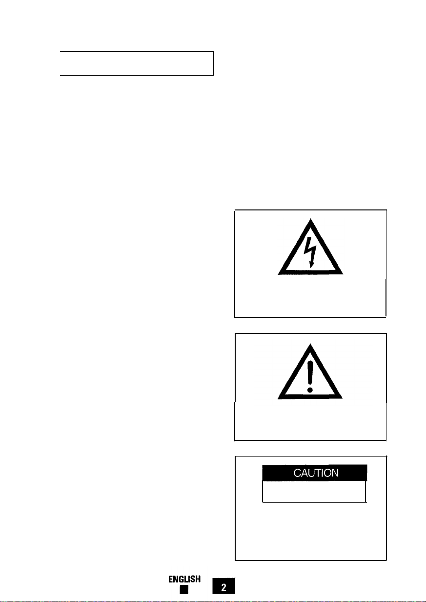
Warning and Cautions
The lightning flash and arrowhead within
the triangle is a warning sign alerting you
of “dangerous voltage” inside the product.
Appendix contains important reference
information such as the monitor's
specifications, important FCC and IC
operating information, pin assignments and the signal timing
settings that have been preset at the
factory.
Please take the time to read through this
manual so that you can obtain the maximum performance and use from your monitor. After reading the manual, store it in a
safe place for future reference.
ENGLISH 2
The exclamation point within the triangle
is a warning sign alerting you of important
instructions accompanying the product.
RISK OF ELECTRIC SHOCK
DO NOT OPEN
CAUTION : To reduce the risk of electric
shock, do not remove cover (or back). No
user serviceable parts inside. Refer
servicing to qualified service personnel.
Page 5
Features of Your Monitor
The Color Monitor is designed for exceptional screen performance-offering a tight
0.28 mm dot-pitch for resolutions up to
1024 x 768. It also offers an unlimited
number of colors and high refresh rates for
stable, “flicker-free” images.
With this monitor, you have a highcontrast screen that helps eliminate blurring and delivers exceptionally sharp text
and graphics. In addition, the monitor
supports all standard analog modes from
VGA to EVGA.
Other features of the Monitor include :
38 cm ( 15” ) [ 35 cm ( 13.8” ) visual ],
non-glare CRT treatment helps reduce
eyestrain.
Automatically scans horizontal frequencies from 30 KHz to 50 KHz and
vertical frequencies from 50 Hz to
120 Hz.
Supports VESA flicker-free modes,
adding to the image quality.
Microprocessor-based digital control
system saves up to 11 user definable
display settings. Also, includes 11 factory preset display settings.
Monitor provides compatibility with a
wide variety of video standards including IBM VGA, XGA, Super-VGA, Apple
Macintosh II and 1024 x 768 non-interlaced.
Power supply operates on AC 100-240
Volt and 60 Hz / 50 Hz for use worldwide.
Your display has been designed to
operate all power systems, including
“IT” power systems.
PowerSaver, the monitor’s built-in
power management system, provides
advantages such as energy cost savings, the extension of product life and
a decrease in air pollution caused by
power generation.
Optional Feature Macintosh Cable Adapter
l Your dealer offers an optional
MacMaster Cable Adapter for connecting your monitor to the Power
Macintosh, Quadra series, PowerBook
series, Duo Dock systems and most of
today’s popular video cards. Please
consult your dealer for information
about this optional feature.
“Safe-workplace” design
SyncMaster 15GLe complies with
SWEDAC ( MPR II ) recommendations
for reduced electric and magnetic
fields.
3
Page 6

Safety Tips
1.
Before connecting the AC power cord
to an outlet, make sure the voltage
designation on your monitor corresponds to the local electrical supply.
2.
Never insert anything metallic into the
monitor openings. Doing so may create the danger of electric shock.
3.
To avoid electric shock, never touch
the inside of the monitor. Only a qualified technician should open the monitor’s case.
4.
Never use your monitor if the power
cord has been damaged. Do not allow
anything to rest on the power cord,
and keep the cord away from where
people could trip over it.
Be sure to hold the plug, not the cord,
5.
when disconnecting the monitor from
an electric socket.
Openings in the monitor cabinet are
6.
provided for ventilation. To prevent
overheating, these openings should
not be blocked or covered. Also, avoid
using the monitor on a bed, sofa, rug
or other soft surface. Doing so may
block the ventilation openings in the
bottom of the cabinet. If you put the
monitor in a bookcase or some other
enclosed space, be sure to provide
adequate ventilation.
7.
Put your monitor in a location with low
humidity and a minimum of dust.
Avoid places like damp basements or
dusty hallways.
8.
Do not expose the monitor to rain or
use it near water ( in kitchens, next to
swimming pools, etc. ). If the monitor
accidentally gets wet, unplug it and
contact an authorized dealer immediately. You can clean the monitor with
a damp cloth when necessary, but be
sure to unplug the monitor first.
9.
Place the monitor on a solid surface,
and treat it kindly. The screen is made
of glass and can be damaged if
dropped or sharply hit.
Locate your monitor near an easily
10.
accessible AC outlet.
11.
If your monitor does not operate normally-in particular, if there are any
unusual sounds or smells coming from
it-unplug it immediately and contact
an authorized dealer or service center.
12.
High temperatures can cause problems. Don’t try to use your monitor in
direct sunlight, and keep it away from
heaters, stoves, fireplaces and other
sources of heat.
Unplug the monitor when it is going to
13.
be left unused for an extended period
of time.
14. Unplug your monitor from the AC outlet before any service.
ENGLISH
n
4
Page 7
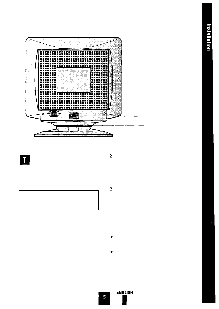
Signal Input
AC Cord Inlet
his section of the User’s Manual
explains how to connect the Color
Monitor to IBM or PC-compatible
computers, as well as Apple Macintosh
computers.
Connection to Your Computer—
IBM or PC-Compatible
Your Color Monitor complements a wide
range of IBM and PC-compatible systems.
To attach the monitor to this type of system, follow these instructions:
1.
Turn off the power to the monitor and
computer.
Connect one end of the signal cable
(provided with your monitor) to the DSUB connector on the rear of the monitor. Tighten the screws on the signal
cable.
Connect the other end of the signal
cable to the video connector on your
computer’s video controller. Tighten
the screws of the signal cable to
ensure proper connection.
Note: Your computer system has one of
two configurations:
The video controller is built into the
computer.
The video controller is in the form of a
display adapter ( also referred to as a
video card, graphics card, graphics
board, or graphics adapter ).
Page 8
Both configurations have a video connector (sometimes called a video port).
If you are not sure which connector is
the video connector, consult your computer or display adapter manual.
4.
Connect one end of the power cord to
the monitor and the other end to the
power outlet.
5.
Turn on the monitor and the computer.
Before turning on power to the
monitor and computer : Check the
User’s Manual of your computer for
instructions about turning on equipment connected to the computer. Also,
check for any instructions concerning
your video system when using a multisync monitor. In some cases, jumper
or switch settings may be required for
the display adapter to output extended
resolution modes.
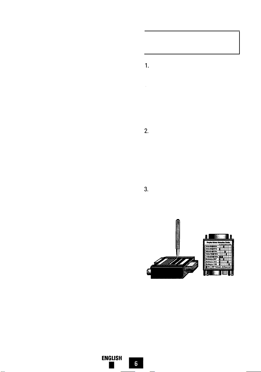
To turn on monitor: Use the power
switch on the monitor’s front panel.
The LED indicator should glow green
(
see Basic Controls and LED Indicator
Functions, page 9 ).
Connection to Your ComputerMacintosh Computer
I
This monitor requires a cable adapter
for use with a Macintosh computer.
The MacMaster Cable Adapter supports all monitors and all Macintosh,
Centris, Quadra, Duo Dock, and Power
Macintosh computers. If you do not
already have a cable adapter, check
with your computer dealer.
Refer to your computer and cable
adapter User’s Manuals to help determine the appropriate display mode
and resolution. This monitor supports
resolutions up to 832 x 624 for the
Macintosh, the resolution most highly
recommended is 832 x 624.
Set the display mode and resolution
using the DIP switches on the cable
adapter.
6
Page 9
4.
Power off your Macintosh computer
and monitor including other peripheral
devices.
5.
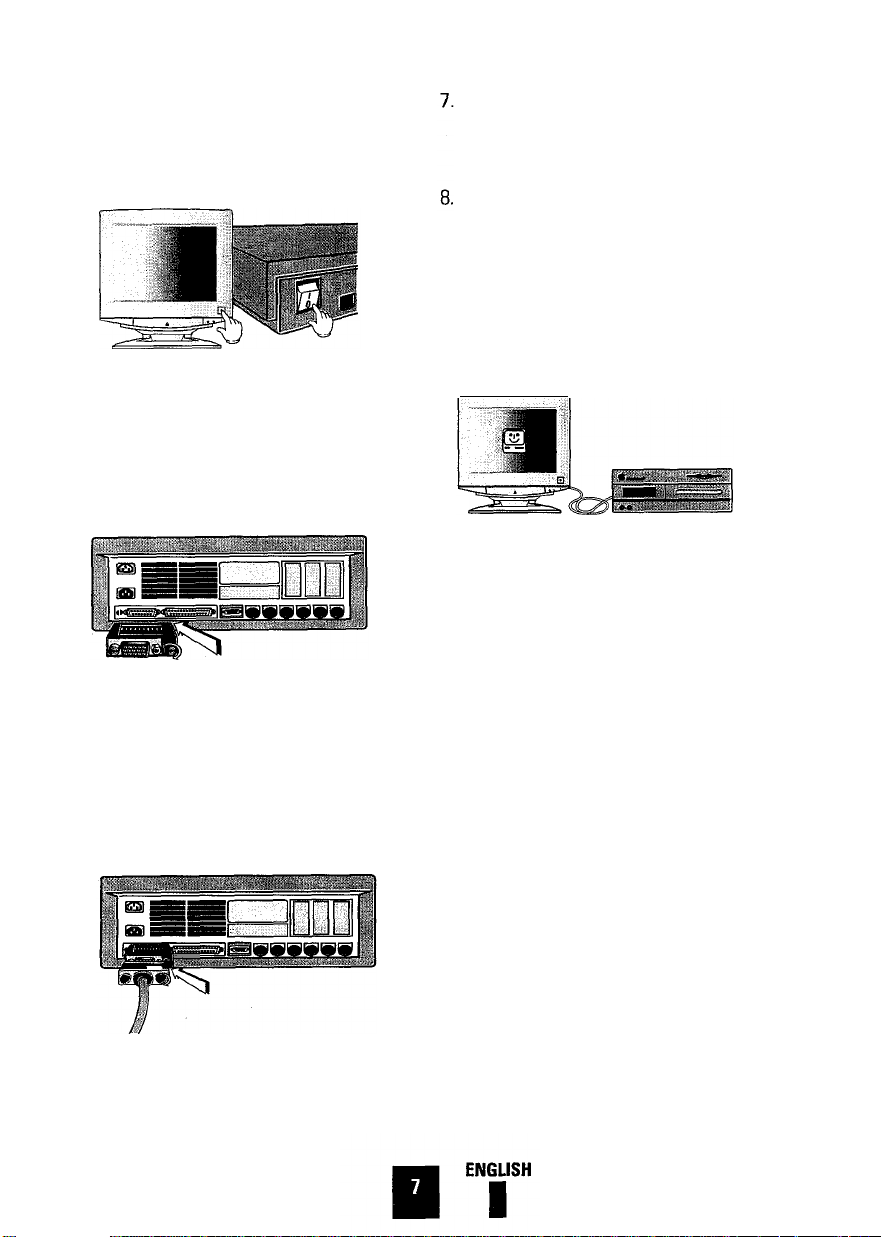
Connect the cable adapter to the video
port of the Macintosh computer.
Tighten the screws on the cable
adapter.
Connect one end of the power cord to
the monitor and other end to the
power outlet.
Power on your monitor and Macintosh
computer. If you see any message on
your monitor screen, installation is
done. If you do not see any messages,
check each of your connections and
DIP switch settings and reboot your
system.
9.
If you need more information, please
refer to the MacMaster Cable Adapter
Users Manual, or contact the
Technical Support Center.
6.
Connect the monitor signal cable to
the other end of the cable adapter.
Tighten the screws of the monitor sig-
nal cable onto the cable adapter to
ensure proper connection.
7 English
Page 10
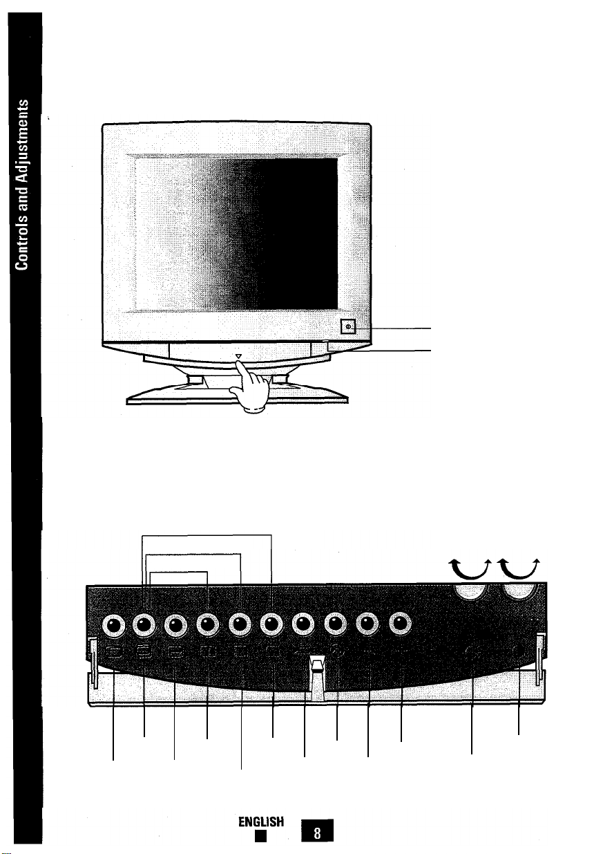
Front View
Control Panel
Press the center of
the control panel to
gain access to these
controls.
1. Power Button
2. Power Indicator
( Dual Color)
6. V-Position
5. H-Position
17. Vertical Linearity
Pinbalance Parallelogram
16. Pinbalance
15. Parallelogram
8. V-Size
7. H-Size
9. Side Pincushion
10. Trapezoid
12. Degauss 14. Increase
11. Recall 13. Decrease
8
3. Contrast
4.
Brightness Control
Control
Page 11
his section of the User’s Manual
shows you the location of each front
panel control explains their functions, and
provides examples that illustrate how to
properly adjust these controls.
Controls and Their Locations
Before operating the monitor take the time
to familiarize yourself with the locations
and functions of all monitor control buttons so you can make adjustments for
optimum performance.
Basic Controls and
LED Indicator Functions
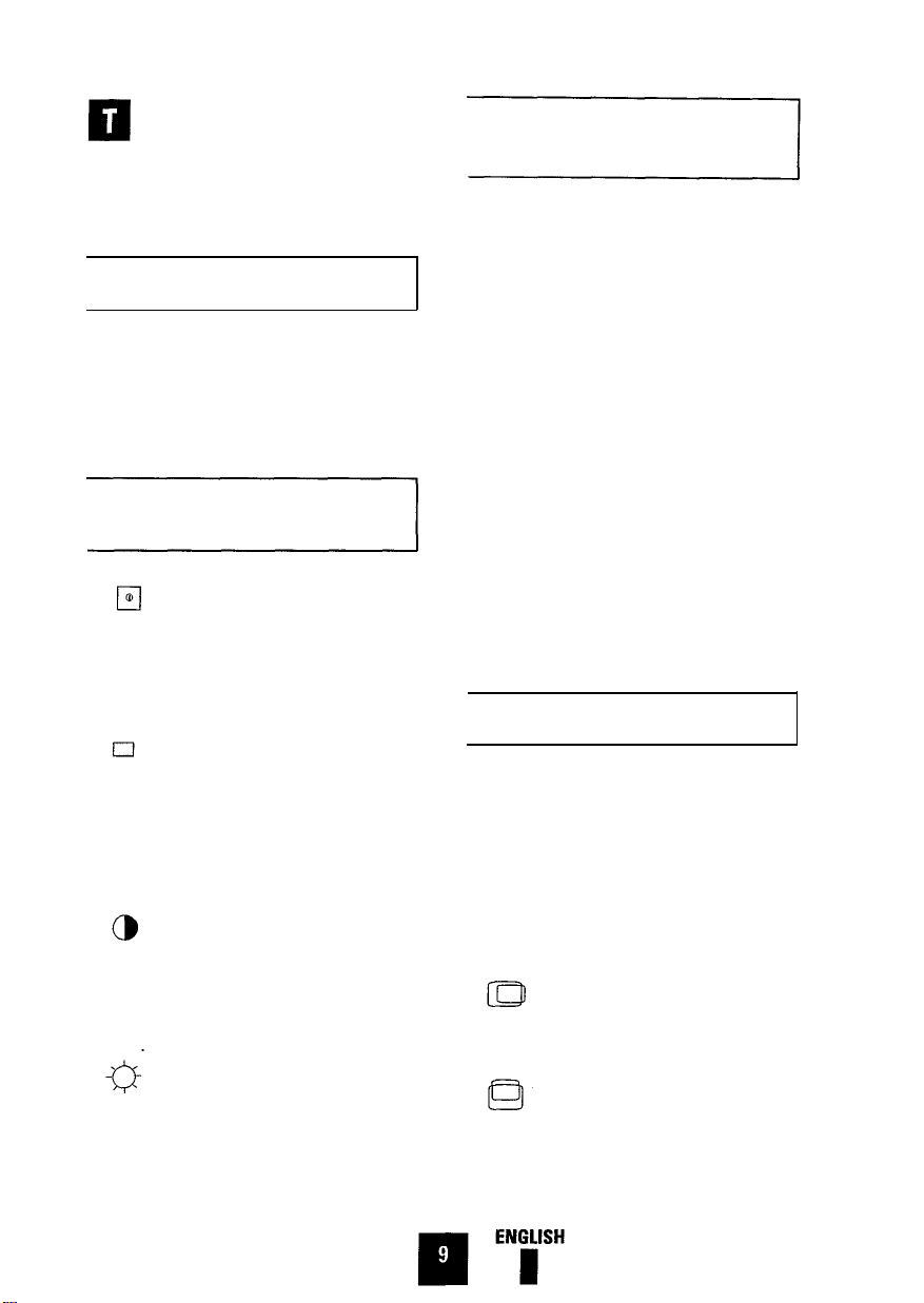
1. Power Button
Use to button monitor power on and off.
Push the power button once to turn monitor
on. The indicator LED is green. Push the
switch again to turn monitor off.
2. Power Indicator ( Dual Color )
While the monitor is on and you are not
making adjustments, the indicator LED is
green. As soon as power is on or while
making adjustments, the indicator LED is
orange.
3. Contrast Control
Use to adjust the contrast level of the
image. The contrast dial controls the dif-
ference between dark and light areas of
the display image.
4. Brightness Control
Use to adjust the overall brightness of the
display stet.
Microprocessor Controls
and Functions
The monitor has factory mode display
settings for each of the signals listed in
the standard Timing Signal Chart ( see
Appendix pages 18 and 19 ). As a result,
when the monitor senses one of the stan-
dard timing signals, it automatically
adjusts to an optimum size and position.
However, you may wish to adjust the mon-
itor to your own preferred settings rather
than those preset at the factory. The monitor’s microprocessor saves your preferred
settings for your computer’s timing signal.
It automatically uses your settings each
time the monitor senses that timing signal.
If you change your video card or computer,
the monitor will use the appropriate settings for the new timing signal. The moni-
tor saves up to 11 user defined settings.
Control Function Buttons
Use these buttons to select the desired
display adjustment function. The indicator
LED will glow orange showing that the
function has been activated. Then use the
display Adjustment Control ( + and -) to
adjust the display. Approximately two sec-
onds after your adjustments are complete,
the settings will automatically save.
5. Horizontal Position
Use this button to adjust the horizontal
position ( centering ) of the display.
6. Vertical Position
Use this button to adjust the vertical posi-
tion ( centering ) of the display.
9
Page 12
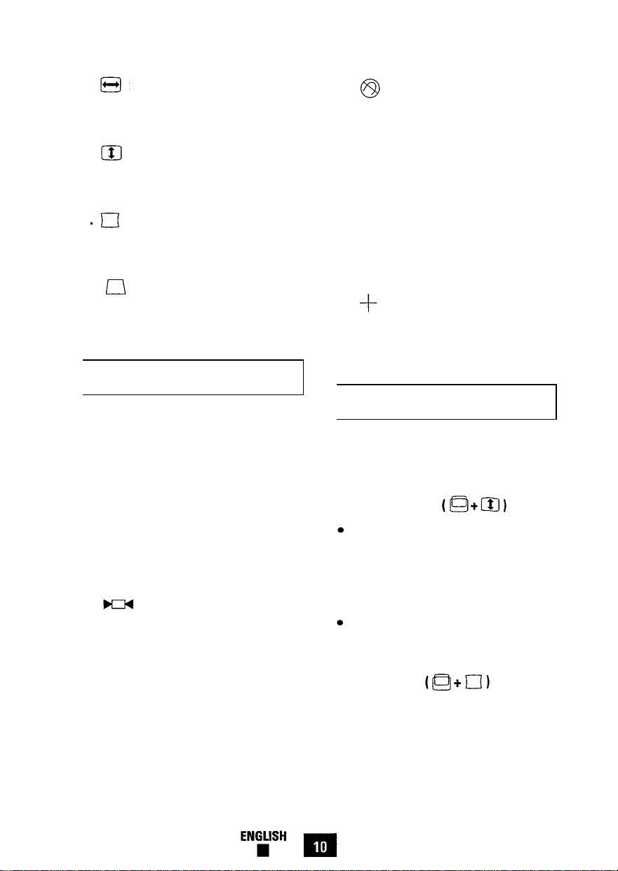
7. Horizontal Size
12. Degauss
Use this button to adjust the horizontal
size ( width ) of the display area.
8. Vertical Size
Use this button to adjust the vertical size
( height ) of the display area.
9. Side Pincushion
Use this button to correct a bowing in or
out of the display area.
10. Trapezoid
Use this button to correct a trapezoid
( shape ) of the display area.
Display Adjustment Buttons
Use these buttons to adjust the display
area while a control function is imple-
mented ( the indicator’s color is orange ).
However, you cannot adjust the display
area when a control function is disabled
( the indicator’s color is green ).
Magnetic fields can build up on the CRT
and cause color impurity. Use the degauss
button to demagnetize the CRT. Push the
button once to activate the degaussing circuit. The degaussing circuit automatically
turns itself off after a few seconds.
13. — Decrease
Use this button to decrease the value of
the selected function. See Adjustment
Examples, pages 12 and 13.
14.
Increase
Use this button to increase the value of
the selected function. See Adjustment
Examples, pages 12 and 13.
Technical Control Functions
Your monitor has the following technical
control functions for the correction of geometric distortion.
15. Parallelogram
Note: 3 to 4 seconds after completing
adjustments your settings automatically
save, and the indicator returns to its nor-
mal status “green.”
11. Recall
Use this button to recall factory modes
settings. Press the button for 2 to 3 seconds until the indicator LED color changes
from orange to green.
Caution: This operation resets all of the
data in the user memory area for the current signal timing.
Use and hold both the vertical position
button and vertical size button simultaneously for 4 to 5 seconds, or until
the indicator’s color changes from
orange to green.
Use the Plus ( + ) or Minus (-) button
to control parallelogram of the display
area.
16. Pinbalance
l
Press and hold both the vertical posi-
tion button and side pincushion button
simultaneously for 4 to 5 seconds, or
until the indicator’s color is changes
from orange to green.
10
Page 13
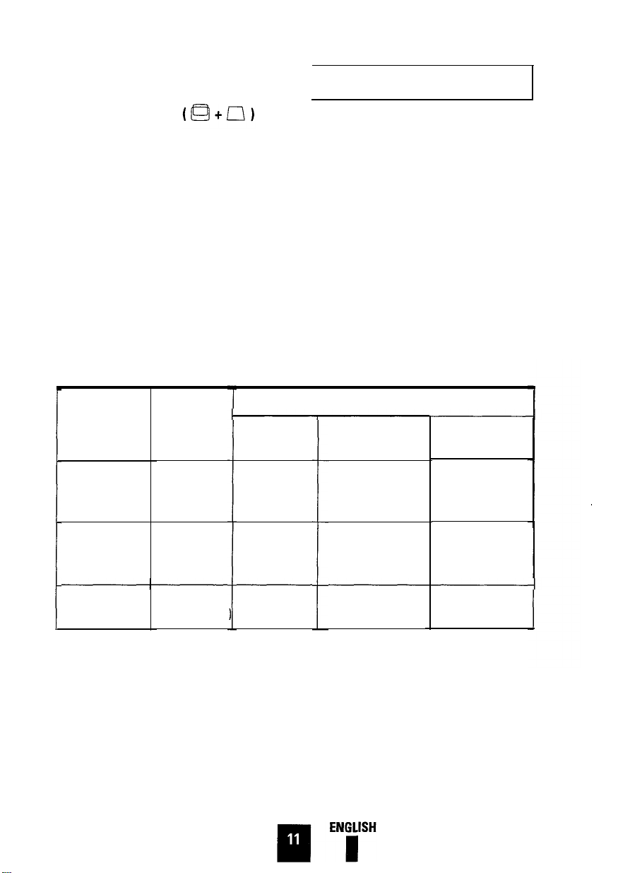
l
Use the Plus (+) or Minus (-) button
to control pinbalance of the display.
Power Management System
17. Vertical linearity
l
Use and hold both the vertical position
button and trapezoid button simultaneously for 4 to 5 seconds, or until the
indicator’s color changes from orange
to green.
l
Use the Plus ( + ) or Minus (-) button
to control vertical linearity of the display area.
This monitor features a built-in power
management system–called
PowerSaver–which operates with your
computer’s video card. To take advantage
of the PowerSaver feature you must use a
VESA DPMS compliant video card.
The PowerSaver runs in four operational
states: On, Stand-by, Suspend and Off.
The modes of operation and time limits
are set through a software utility which
comes with your video card. See table
below for further details.
Table: Display Power Management Signaling ( DPMS ) Standard
Power saving function mode EPA/NUTEK
State
Normal
operation
Stand-by mode
Suspend mode /
Position A1
Horizontal Sync.
Vertical Sync.
Video
Active
Active
Active
Inactive
Active
Blanked
Active
Inactive
Blanked
Power-off mode/
Position A 2
Inactive
Inactive
Blanked
Power
Green
Orange
Indicator
Power
Consumption
Note:
The monitor automatically returns to the normal operation state when horizontal and vertical
85W ( max. )
67.5W ( nominal ) 40.5W ( nominal )
68W ( max. )
Orange / Green
Blinking
Less than
15W
Orange
Blinking
Less than
5W
sync returns. This occurs when you move your mouse or press a key on your keyboard. When you turn
the power off in Power-off mode, the LED indicator may continuosly blink on-off for 4 to 15 seconds.
This monitor is EPA Energy Star compliant and NUTEK compliant when used with a computer
equipped with VESA DPMS function. If your computer system cannot support a display power management function, you may purchase an optional DPMS software program to have power saving function. Please contact Samsung, or your dealer, for more information.
For Energy conservation, turn your monitor OFF when the monitor is not needed, or when leaving it
unattended for long periods.
11
Page 14
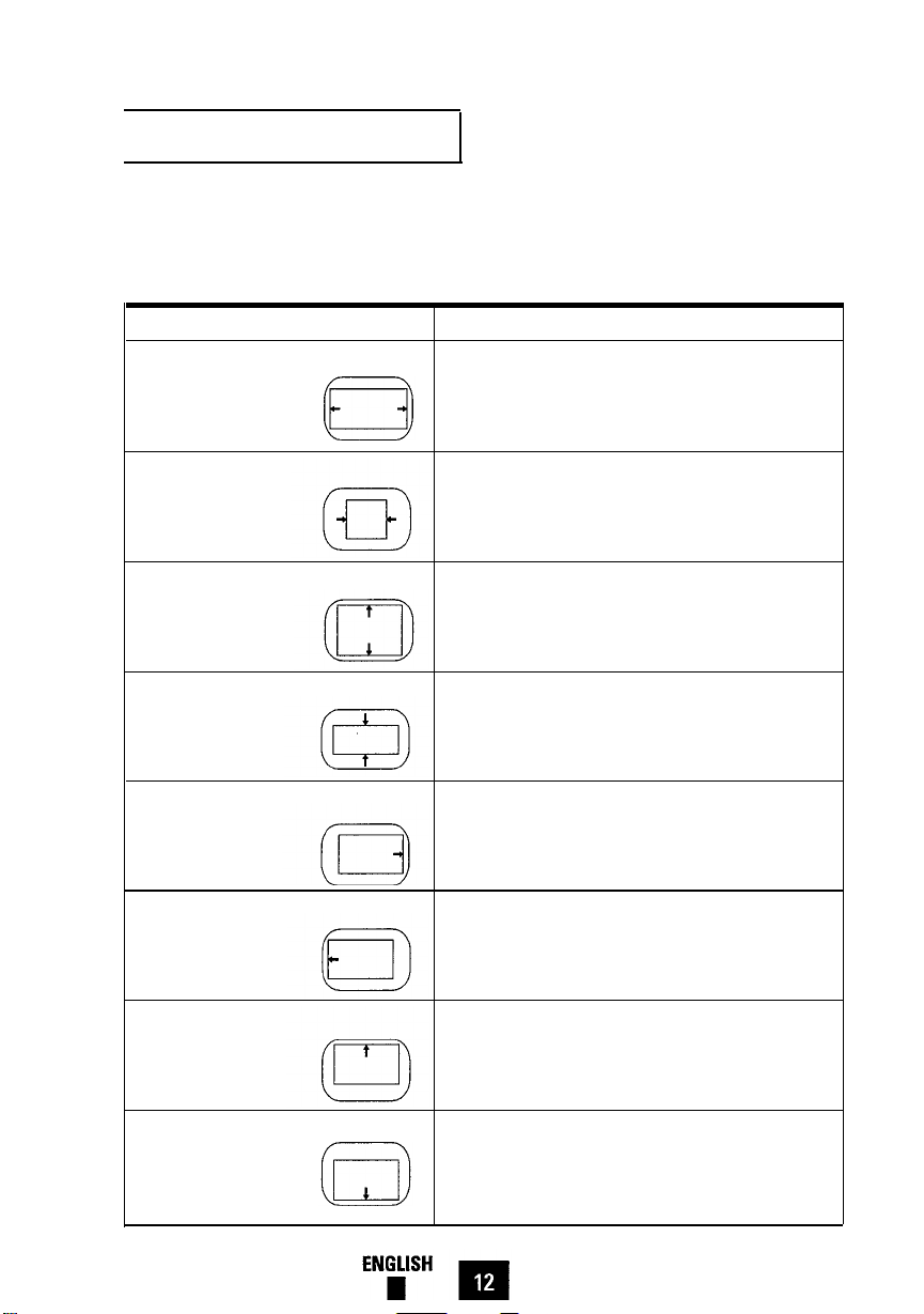
Adjustment Examples
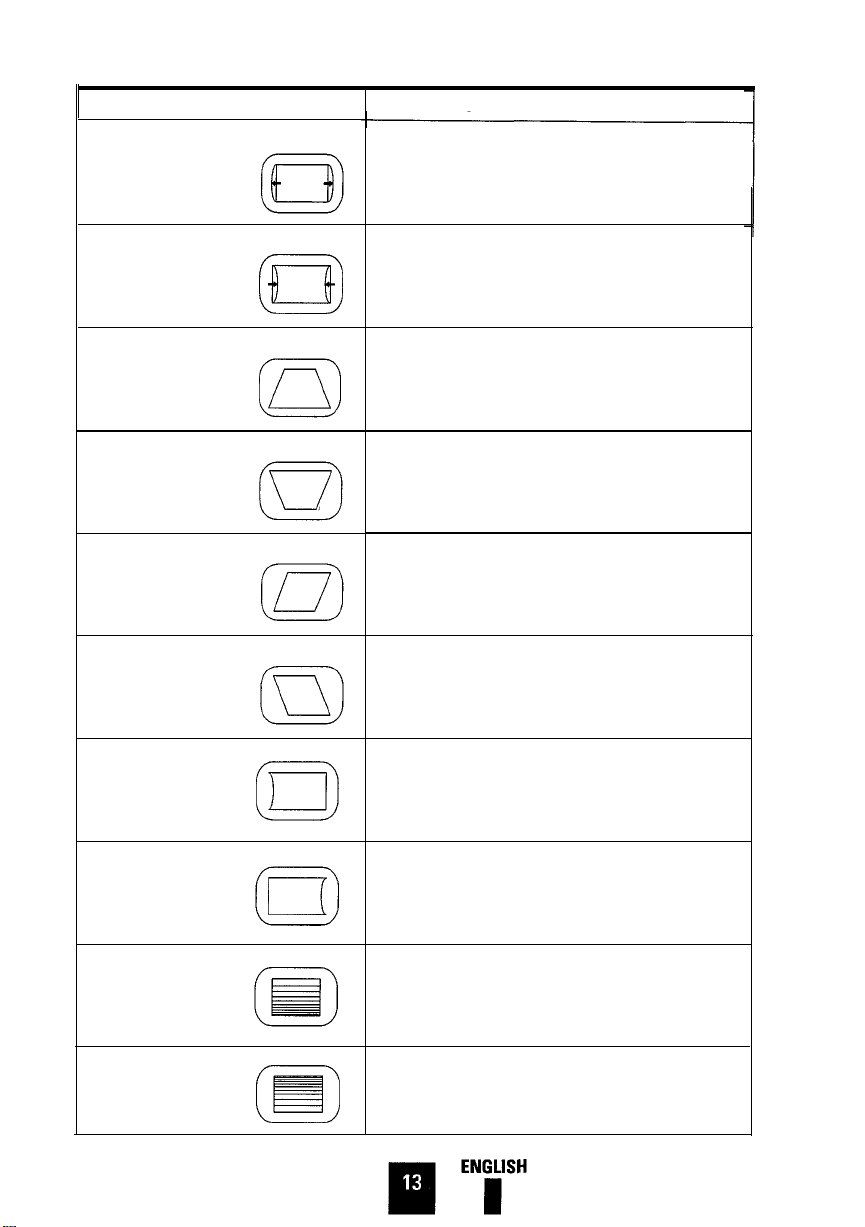
The following chart provides an illustrated
reference guide for adjusting the picture of
your monitor’s display.
Condition
Picture is too wide.
Picture is too narrow.
Picture is too large vertically.
Picture is too small vertically.
Picture shifted to the right.
Picture shifted to the left.
Control Usage Instruction
Push the Horizontal Size button.
Push the Minus button (–) to decrease the Horizontal Size.
Push the Horizontal Size button.
Push the Plus button (+) to increase the Horizontal Size.
Push the Vertical Size button.
Push the Minus button (–) to decrease the Vertical Size.
Push the Vertical Size button.
Push the Plus button (+) to increase the Vertical Size.
Push the Horizontal Position button.
Push the Minus button (–) to move image to the left.
Push the Horizontal Position button.
Push the Plus button (+) to move image to the right.
Picture shifted upward.
Picture shifted downward.
Push the Vertical Position button
Push the Minus button (-) to move the image down.
Push the Vertical Position button.
Push the Plus button (+) to move the image up.
12
Page 15
Condition
Vertical sides are not straight.
( bowing out )
Control Usage Instruction
Push the Side Pincushion button.
Push the Minus button (–) to move sides in
Vertical sides are not straight.
( bowing in )
Bottom size is too large.
Bottom size is too small.
Vertical sides are tilted right.
Vertical sides are tilted left
Left Pin balance is not straight.
Push the Side Pincushion button.
Push the Plus button (+) to move sides out.
Push the Trapezoid button.
Push the Minus button (-) to decrease the bottom size.
Push the Trapezoid button.
Push the Plus button (+) to Increase the bottom size.
Push the Vertical Position and Vertical Size buttons simultaneously.
Push the Minus button (–) to adjust to the left.
Push the Vertical Position and Vertical Size buttons simultaneously.
Push the Plus button (+) to adjust to the right.
Push the Vertical Position and Side Pincushion buttons simultaneously.
Push the Plus button (+) to move left side out.
Right Pin balance
IS
not straight.
Bottom Vertical linearity is narrow.
Top Vertical linearity is narrow.
Push the Vertical Position and Side Pincushion buttons simultaneously.
Push the Minus button (-) to move right side out.
Push the Vertical Position and Trapezoid buttons simultaneously.
Push the Plus button (+) to correct vertical linearity.
Push the Vertical Position and Trapezoid buttons simultaneously.
Push the Minus button (-) to correct vertical linearity.
13
Page 16
his section of the User’s Manual
offers a handy chart that may be
used to quickly correct problems with the
monitor should any occur.
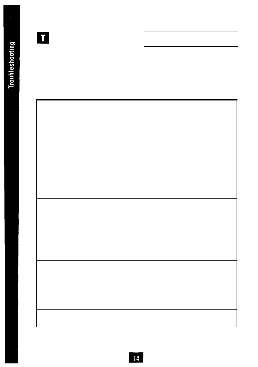
Troubleshooting Chart
Before calling an authorized service center, please check this troubleshooting
chart. Many of the problems that can
occur are easily corrected without the
need of a technician.
Problem
There is no display image.
Image rolls or tears.
Image is too dark
or too bright.
LED indicator color is
blinking on-off orange.
Image is too large
or too small.
Image is only raster.
Item to Check
l
Check power switch.
LED should be turned on.
l
Check to see that power cordl Rear
is plugged in.
l
Check to see that signal
cable is connected.
l
Check to see that signal
source is turned on.
l
Check to see that signal
cable pin assignment is correct.
l
Check to see that signal
cable pin assignment is correct.
l
Check to see if the frequency
of the video card is outside
monitor’s capabilities.
l
Use the contrast or brightness
volume to correct the problem.
l
Check to see that signal
cable is connected.
l
Press a key or move mouse.
l
Use the Horizontal Size or
Vertical Size button to adjust the
width or height of the image.
l
Check to see that signal
cable is connected.
Location
l
Front panel
l
Rear
l
Your computer
l
Rear / Your computer
Documentation /
This manual, page 17
l
Rear / Your computer
Documentation /
This manual, page 17
l
Your computer manual
video card
l
Front Panel
l
Rear/Your computer
l
Your computer
l
Front Panel
l
Rear
ENGLISH
14
Page 17
his section of the User’s Manual
contains important reference infor-
mation such as the monitor’s
Specifications ( page 15 ), important FCC
and IC operating information ( page 16
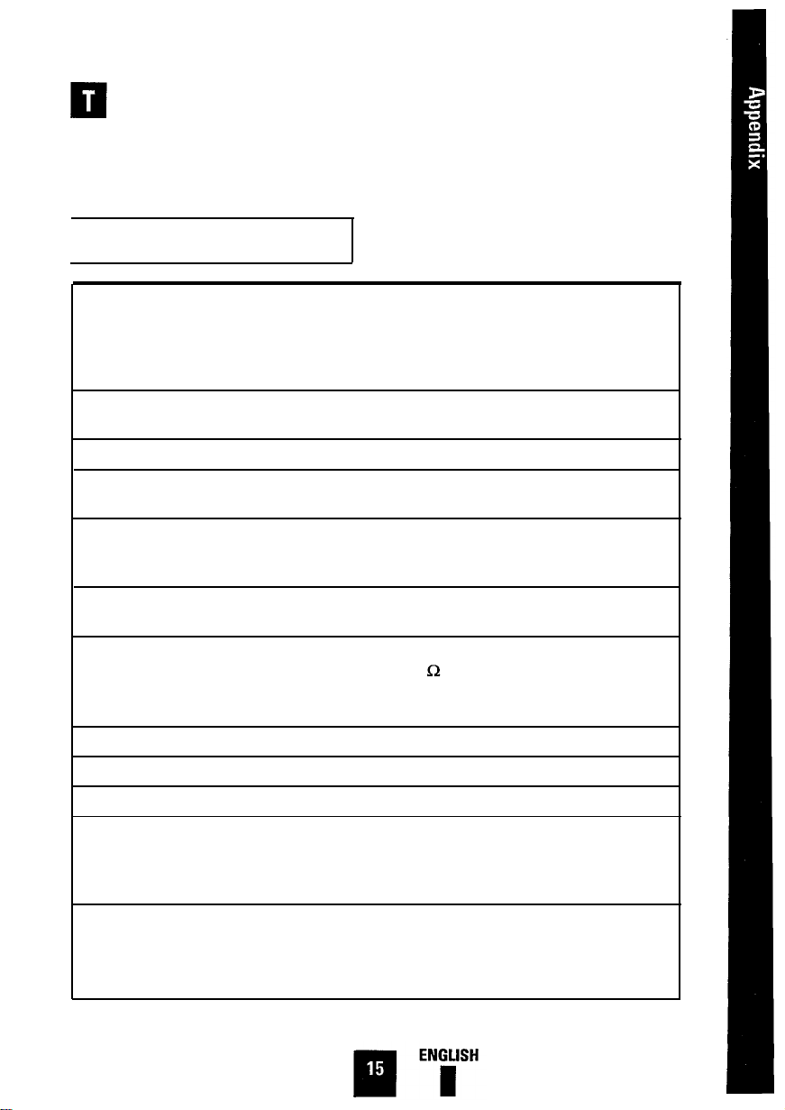
Specifications
and 17 ), Pin assignments ( page 17 ), and
the Factory Modes Timing Signal Chart.
( pages 18 and 19 ).
Picture Tube
Synchronization
Display Color
Maximum Resolution
Active Display Size
Maximum Display Size
Input Signal
Maximum Pixel Clock
Power Supply
Power Consumption
Dimensions/Weight
(Approximately)
Environmental Considerations
l
38 cm ( 15” ) Flat Face Tube Type [35 cm ( 13.8” ) visual.
l
90° Deflection
l
0.28 dot pitch, Semi-tint, Non-glare
l
Anti-Static Silica coating
l
lnvar Shadow Mask
l
Horizontal: 30 kHz to 50 kHz ( automatic )
l
Vertical: 50 Hz to 120 Hz ( automatic )
l
Unlimited colors
l
Horizontal: 1024 dots
l
Vertical: 768 lines
l
Horizontal: 267 mm ± 3 mm ( 10.5” + 0.19” )
l
Vertical: 200 mm ± 3 mm ( 7.87” ± 0.19” )
( Active display size is changed by timing signal )
l
Horizontal: 280 mm ( 11.02” )
l
Vertical: 210 mm ( 8.27” )
l
Video Signal: Analog 0.714 Vpp
Positive at 75
l
Separate Sync.: TTL Level, Positive or Negative
l
Composite Sync.: TTL Level, Positive or Negative
l 65MHz
l AC100-240Volt±10%,60Hz/50Hz±3Hz
l
85 Watt maximum
l
Unit: 393.5 x 373 x 400 mm; 13.3 kg
Terminated
15.5” x 14.7” x 15.7” ( H x W x D ) 29.3 lb
l
Carton: 450 x 465 x 517 mm; 15.3 kg
17.7” x 18.3” x 20.4” ( H x W x D ) 33.7 lb
l
Operating Temperature: 32°F to 104°F
( 0°C to 40°C ) Humidity: 10% to 80%
l
Storage Temperature: -4°F to 113°F
( -20°C to 45°C )- Humidity: 5% to 95%
Note: Design and specifications are subject to change without prior notice.
15
Page 18
FCC Information
User Instructions
The Federal Communications Commission
Radio Frequency Interference Statement
includes the following warning :
Note:
This equipment has been tested
and found to comply with the limits for a
Class B digital device, pursuant to Part 15
of the FCC Rules. These limits are
designed to provide reasonable protection
against harmful interference in a residential installation. This equipment generates,
uses and can radiate radio frequency energy and, if not installed and used in accordance with the instructions, may cause
harmful interference to radio communications. However, there is no guarantee that
interference will not occur in a particular
installation.
If this equipment does cause harmful
interference to radio or television reception, which can be determined by turning
the equipment off and on, the user is
encouraged to try to correct the interference by one or more of the following measures:
l Reorient or relocate the receiving
antenna.
l Increase the separation between the
equipment and receiver.
l Connect the equipment into an outlet
on a circuit different from that to
which the receiver is connected.
l
Consult the dealer or an experienced
radio /TV technician for help.
User Information
Changes or modifications not expressly
approved by the party responsible for compliance could void the user’s authority to
operate the equipment.
If necessary, consult your dealer or an
experienced radio/television technician
for additional suggestions. You may find
the booklet called “How to Identify and
Resolve Radio /TV Interference Problems”
helpful. This booklet was prepared by the
Federal Communications Commission. It is
available from the U.S. Government
Printing Office, Washington, DC 20402,
Stock Number 004-000-00345-4.
Warning
User must use shielded signal interface
cables to maintain FCC compliance for the
product.
Provided with this monitor is a detachable
power supply cord with IEC320 style terminations. It may be suitable for connection
to any UL Listed personal computer with
similar configuration. Before making the
connection make sure the voltage rating of
the computer convenience outlet is the
same as the monitor and that the ampere
rating of the computer convenience outlet
is equal to or exceeds the monitor voltage
rating.
For 120 Volt applications use only UL
Listed Detachable Power cord with NEMA
configuration 5-15P type (parallel blades)
plug cap. For 240 Volt applications use
only UL Listed Detachable power supply
cord with NEMA configuration 6-15P type
(tandem blades) plug cap.
16
Page 19
IC Compliance Notice
This Class B digital apparatus meets all
requirements of the Canadian
Interference-Causing Equipment
Regulations of ICES-003.
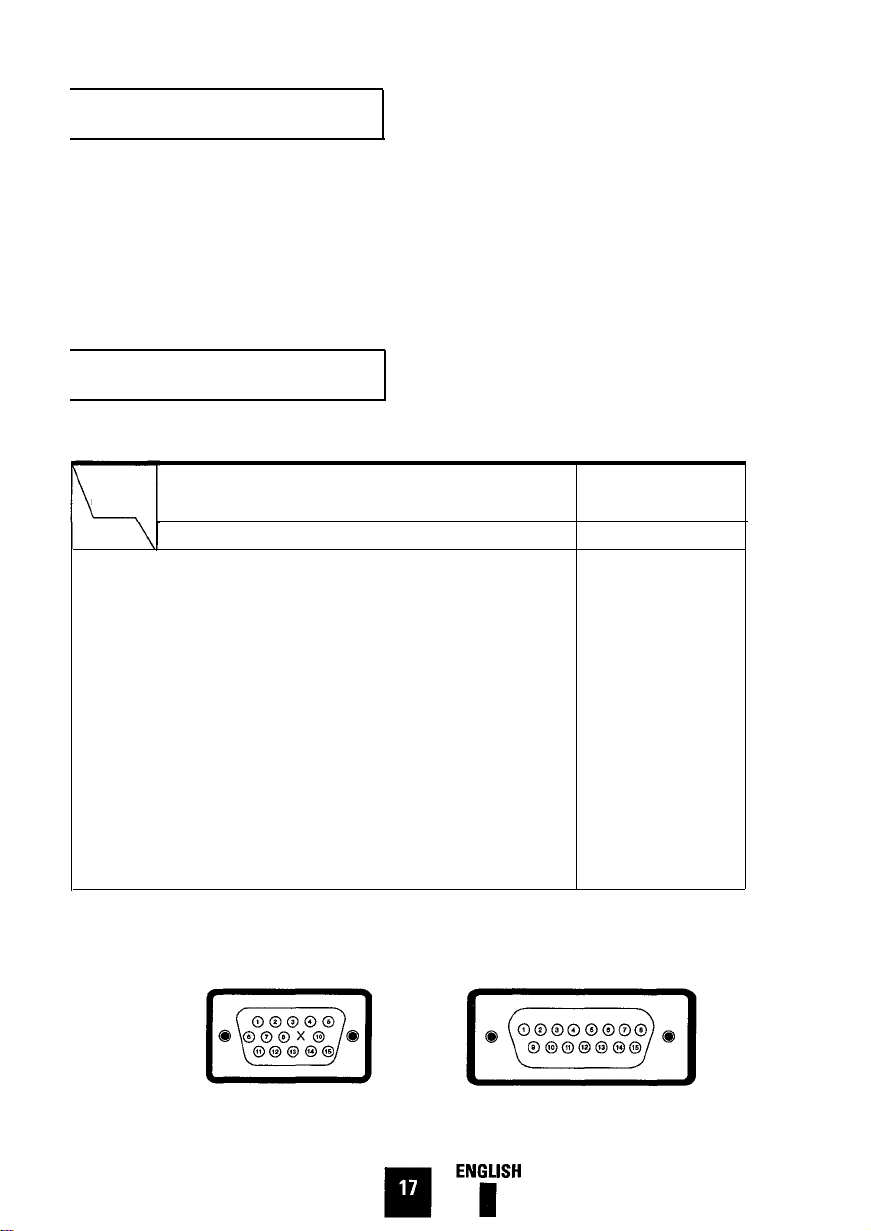
Pin Assignments
Sync
Type
Pin No.
1
2
3
4
5
6
7
8
9
10
11
12
13
14
15
Both Ends of the Signal Cable
( Figure 1 )
Separate
Red
Green
Blue
GND
DDC Return
GND-R
GND-G
GND-B
Reserved
GND-Sync / Self-Raster
GND
DDC Data
H-Sync
V-Sync
DDC Clock
Cet appareil numérique de la Classe B
respecte toutes les exigences du
Règlement ICES-003 sur le Matériel
brouilleur du Canada.
Cable Adapter
( Figure 2 )
Composite
Red
Green
Blue
GND
DDC Return Green
GND-R
GND-G
GND-B Reserved
Reserved Blue
GND-Sync / Self-Raster Sense 2
GND
DDC Data
H/V-Sync Gnd-B
Not Used
DDC Clock H-Sync
Apple Macintosh
Gnd-R
Red
H/V Sync
Sense 0
Gnd-G
Sense 1
Gnd
V-Sync
Gnd
Figure 1: Male Type
Figure 2: Male Type
17
Page 20
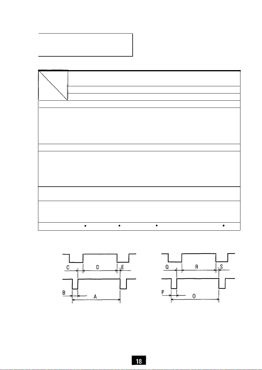
Factory Modes Timing
Signal Chart
Mode
VGA1/70Hz
Timing
fH
(kHz)
A
µsec 31.778
B
µsec 3.813
C
µsec
D
µsec
E
µsec
(Hz)
fv
O msec
P msec
Q msec
R msec
S msec
Clock Freq.
(MHz)
Polarity
H.-Sync.
V.-Sync.
Negative
Remark
IBM
640X350
31.469
1.907
25.422
0.636
70.086
14.268
0.064
1.907
11.122
1.176
25.175
VGA2/70Hz
720X400 640X480
31.469
31.777
3.813
1.907
25.422
0.636
70.087
14.268
0.064
1.080
12.711
0.413
28.322
VGA3/60Hz
31.469
31.778
3.813 3.920
1.907 1.247
25.422
0.636 0.178
59.940
16.683 11.500
0.064
1.048
15.253
0.318
25.175
Positive Negative Negative
Positive Negative
VESA
XGA/87iHz
1024X768
35.522
28.151
800/60Hz
800x600
37.879
26.400
3.200
2.200
22.806
20.000
1.000
86.958
60.317
16.579
0.113
0.563
10.810
0.014
44.900
0.106
0.607
15.840
0.026
40.000
Positive Positive
Positive
Positive
Interlace
Horizontal
ENGLISH
n
Vertical
18
Page 21
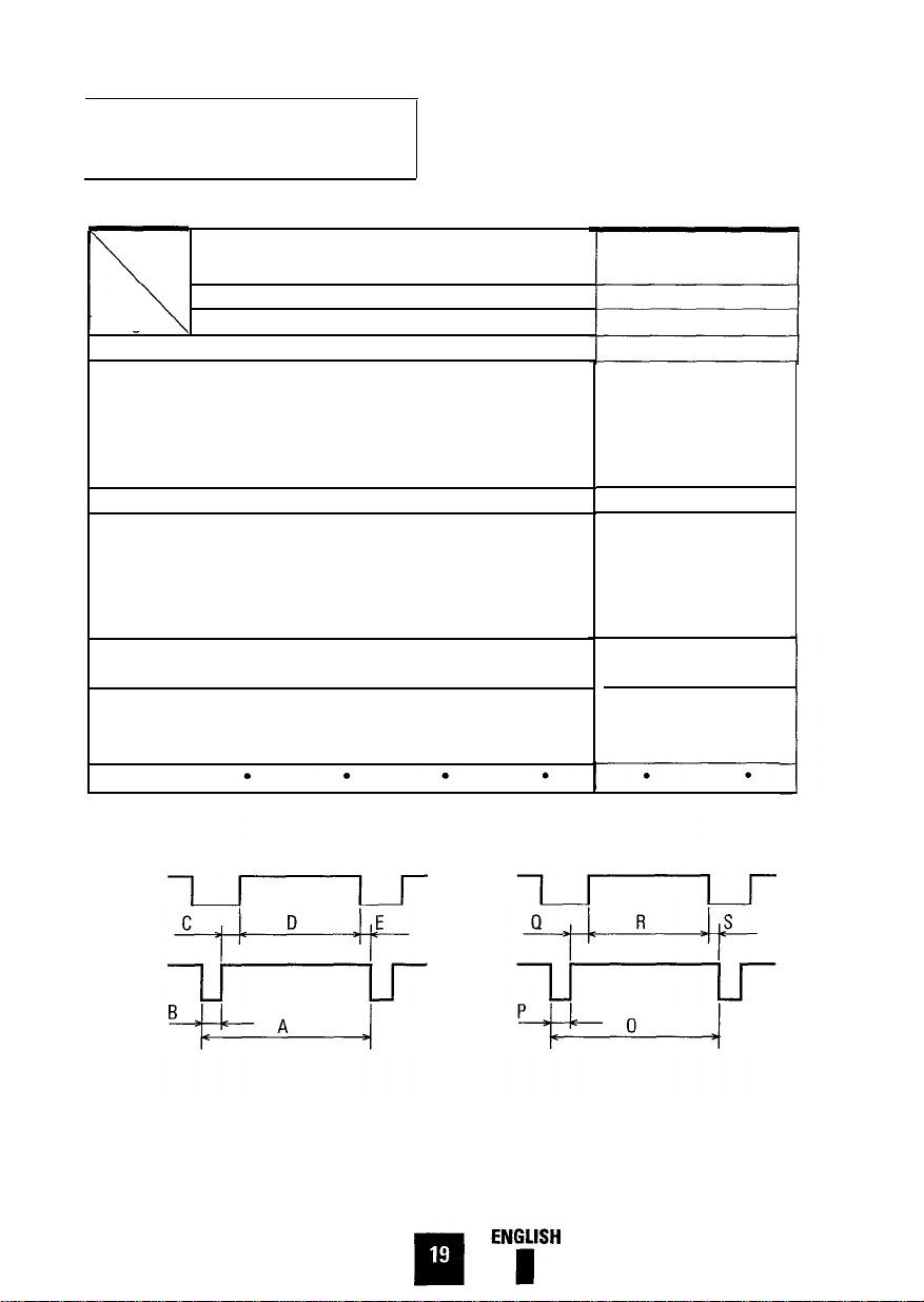
Factory Modes Timing
Signal Chart
Mode
Timing
fH(kHz)
A
µsec
B
µsec
C
µsec
D
µsec
E
µsec
fv (Hz)
O msec
P msec
Q msec
R msec
S msec
640/72Hz
640X480
37.861
26.413
1.270
4.064
20.317
0.762
72.809
13.735
0.079
0.739
12.678
0.237
640/75Hz 800/75Hz
640X480 800x600
37.500 46.875
26.667 21.333
2.032
3.810 3.232
20.317 16.162
0.508
75.000
13.333 13.333
0.080
0.427
12.800 12.800
0.027 0.021
Clock Freq.
(MHz)
31.500
31.500 49.500
Polarity
H.-Sync.
Negative Negative
V.-Sync. Negative Negative
Remark
VESA
1.616
0.323
75.000
0.064
0.448
Positive
Positive
1024/60Hz
1024X768
48.363
20.677
2.092
2.462
15.754
0.369
60.004
16.666
0.124
0.600
15.880
0.062
65.000
Negative
Negative
MACINTOSH
640/67Hz
640X480
832/75Hz
832X624
35.000
28.571
2.116 1.117
3.175
21.164
14.524
2.116
66.667 74.551
15.000
13.414
0.086 0.060
1.114
13.714
12.549
0.086
30.240
Negative
Negative
Negative
Negative
49.726
20.110
3.910
0.559
0.784
0.020
57.284
Horizontal
Vertical
19
Page 22
VCCI Information
PLUG AND PLAY
This equipment is in the 2nd Class catego-
ry ( information equipment to be used in a
residential area or an adjacent area thereto ) and conforms to the standards set by
the Voluntary Control Council For
Interference by Data Processing Equip-
ment and Electronic Office Machines
aimed at preventing radio interference in
such residential area. When used near a
radio or TV receiver, it may become the
cause of radio interference. Read the
instructions for correct handling.
Samsung’s adoption of the new Microsoft
Windows 95 Plug and play solution eliminates complicated and time consuming
setup. It allows you to install your monitor
in a Plug and Play compatible system
without the usual hassels and confusion.
Your PC system can easily identify and
configure itself for use with your monitor.
This monitor automatically tells the PC
system its Extended Display Identification
( EDID ) data using Display Data Channel
( DDC ) protocols so the PC system can
automatically configure itself and optimize
the monitor settings. If desired, the user
can select different settings, but in most
cases, monitor installation is automatic.
20
Page 23

Page 24
BH68-60045A ( Rev.0.0 )
EPA POLLUTION PREVENTER
Printed on the recyclable paper
 Loading...