

Samsung SVP-5300 User Manual
P/No.: 6806-0526-01A
crecom 04.10
SAMSUNG TECHWIN CO., LTD.
145-3, Sangdaewon 1-Dong, Jungwon-Gu,
Sungnam, Kyungki-Do, Korea 462-703
TEL: +82-31-740-8137~8141 FAX: +82-31-740-8145
SAMSUNG OPTO-ELECTRONICS AMERICA, INC.
ELECTORONIC IMAGING DIV.
40 Seaview Drive, Secaucus NJ 07094, U.S.A
TEL: +1-201-902-0347 FAX: +1-201-902-0429
SAMSUNG TECHWIN MOSCOW OFFICE
LENNINGRADSDY PR-KT, 37A. KORP.14
RUSSIA, 125167, MOSCOW
TEL: +7-095-258-9296, 9298 FAX: +7-095-258-9297
SAMSUNG OPTO-ELECTRONICS UK LTD.
Samsung House, 1000 Hillswood Drive
Hillswood BusinessPark Chertsey Surrey KT16 OPS
TEL: +44 (0)1932 455 308 FAX: +44 (0)1932 455 325
TIANJIN SAMSUNG OPTO-ELECTRONICS CO., LTD .
7 Pingchang Rd, Nankai Dist, Tianjin, P.R China
Post Code : 300190
TEL: +86-22-2761-4599 FAX: +86-22-2769-7558
SALES NETWORK
http://www.samsungpresenter.com
www.samsungpresenter.com

CONTENTS
3
SAFETY
PRECAUTIONS
2
Follow these safety instructions when setting up
and using your Video Presenter:
1. Do not place the presenter on an unstable cart,
stand, or table
2. Do not use the presenter near water or sources of
heat.
3. Use the type of power source indicated on the
presenter. If you are not sure of the power
available, consult your dealer or power company.
4. Place the presenter near a wall outlet where the
plug can be easily unplugged.
5. Take the following precautions for the plug.
Failure to comply with these precautions could
result in sparks or fire:
Do not insert the plug into an outlet with dust
present. Insert the plug firmly into the outlet.
6. Do not overload wall outlets, extension cords, or
integral convenience receptacles. This can cause
fire or electric shock.
7. Do not place the presenter where the cord can be
walked on. It may result in fraying or damage to
the plug.
8. Unplug the presenter from the wall outlet before
cleaning. Use a damp cloth for cleaning. Do not
use liquid or aerosol cleaners.
9. Do not block the slots and openings in the
presenter case. They provide ventilation and
prevent the presenter from overheating. Do not put
the presenter on a sofa, rug, or other soft surface
or in a built-in installation, unless proper ventilation
is provided.
10. Never push objects of any kinds through cabinet
slots. Never spill liquid of any kinds into the
presenter.
11. Except as specifically explained in this User's
Manual, do not attempt to service this product
yourself. Refer all servicing to qualified service
personnel. Opening or removing covers may
expose you to dangerous voltages and other
hazards.
12. Unplug the presenter during lightning storms or
when it will not be used for extended periods.
13. Do not place the presenter and remote controller
on top of heat-producing equipment or in a
heated place, such as a car.
14. Unplug the presenter from the wall outlet and
refer servicing to qualified service personnel
under the following conditions:
• When the power cord or plug is damaged or
frayed.
• If liquid has been spilled into the presenter, or it
has been exposed to rain or water.
• If it does not operate normally when you follow
the operating instructions, or if it exhibits a
distinct change in performance, indicating a
need for service.
• If it has been dropped or the cabinet has been
damaged.
15. Don’t take the camera unit unfolded and turn to
the leftmost or rightmost, or the presenter can fall
upside down.
FCC Compliance Statement
This equipment has been tested and found to comply with the limits for a class A digital device, pursuant
to part 15 of the FCC Rules. These limits are designed to provide reasonable protection against harmful
interference when the equipment is operated in a commercial environment. This equipment generates,
uses, and can radiate radio frequency energy and, if not installed and used in accordance with the
instruction manual, may cause harmful interference to radio communications.
Operation of this equipment in a residential area is likely to cause harmful interference in which case the
user will be required to correct the interference at his own expense.
SAFETY PRECAUTIONS 3
WHERE THE VIDEO PRESENTER IS NEEDED 6
CHECKING PARTS 7
Accessories Supplied 7
NAME AND FUNCTION OF PART 8
Front View 8
Control Panel 9
Connectors at the back side 9
Remote Controller 10
CONNECTION 11
To TV or Monitor 11
To TV or Monitor and External AV Device 11
To Power Outlet 12
To Microphone 12
Connecting to PC 13
How to install the Head Lamp 13
How to install the Lightbox 13
OPERATION 14
Using Control Buttons 15
PRECAUTIONS AND STORAGE 18
Storage 18
Safety Precautions 18
TROUBLESHOOTING 20
Installing or Replacing Battery on
Remote Controller 21
SPECIFICATIONS 22
LENS MAGNIFICATION RATE 22
Adapter Lens 22
54
Thank you for purchasing
this product.
Your video presenter can
project a wide variety of
items onto PC, TV (monitor)
with simple handling. High
resolution and definition
ensures fine image quality.
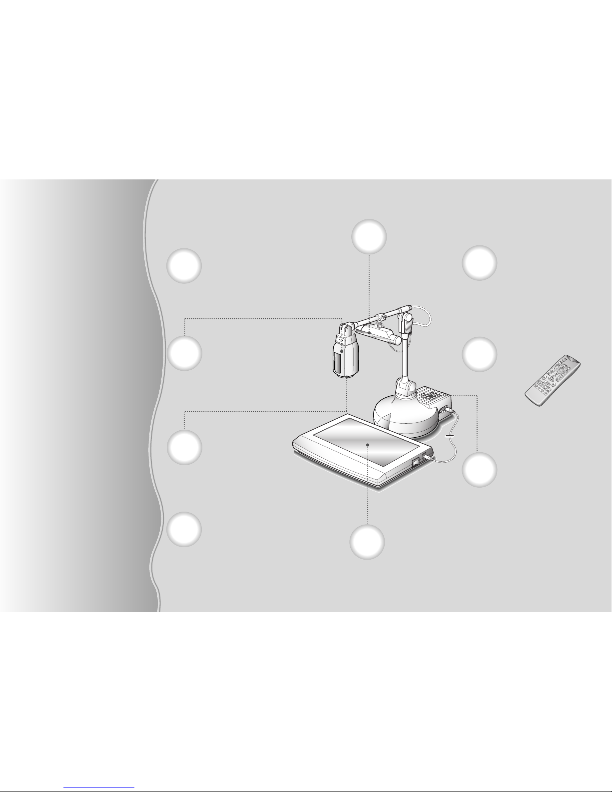
Adapter lens
It is used to project the documents and films
(positive/negative) closely.
Free-angle camera head
The camera head can be freely rotated
through 270° to right or left, 120° to top or
bottom. You can see the surrounding objects
and instruction as well as the data on the plate
Head Lamp
Lamp easily attachable
Control panel
You can control main functions using the
buttons on control panel built in the main
body.
Lightbox (Option)
This backlight illuminator is useful to
project the slides or films. It is easily
attached and removed.
Menu display on the screen
When you control the functions by use of
remote controller or control panel, the
controlling status will be displayed on the
screen.
Remote Controller
All the functions are
controlled by use of remote
controller.
Easy flexible body
Each part can be bent and stretched so that you
can project any type of objects easily.
Automatic focusing
When you press the automatic focusing button,
a precise focusing on the object can be
performed. If automatic focusing is inadequate,
you can focus manually.
Your Video Presenter may be effectively used to
display the design artwork of a catalog or slide
through imaging process.
Education field
You can utilize the presenter as the audio-video aid which
shows the printed materials like textbook, the visual data
and even the products that the students made.
76
WHERE THE VIDEO
PRESENTER IS
NEEDED
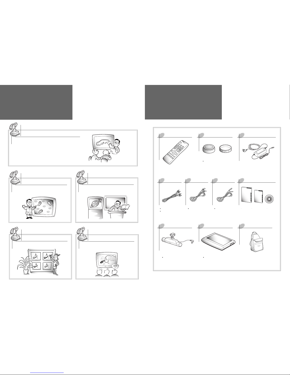
CHECKING PARTS
Medical or scientific research
Accessories Supplied
Remote Controller
Adapter lens and lens cap
Adapter
Head lamp
Light box(Option)
Carring bag
Audio/Video cables
Yellow jack: Video cable
White jack: Audio cable
Required to connect
with a TV equipped
with S-video terminal.
Required to connect to
PC with USB-terminal.
They are attached to the main
body at factory.
S-video cable User’s manualUSB cable
Lamp easily attachable
User’s manual
USB Capture program
User’s manual
CD for program
install
Required to display a slide
or film
You can use the image such as X-ray or slide as it is
on your Video Presenter.
Video conference
The video presenter display clearly the
image of a real thing at hand as well as
detailed data such as report, form, chart,
etc. on the screen. Thus, the entire staffs
concentrate on the same topic so you can
manage the conference efficiently.
Design preview
It can create a powerful visual image by connecting
to multi-vision at the new product presentation or
exhibition.
Presentation and Exhibition
POWER
IRIS AWC
AF
NEGA/POSI
FOCUS
ZOOM
98
NAME AND FUNCTION
OF PART
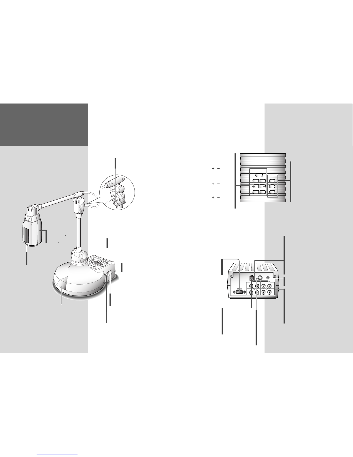
Front View
Connectors at the back side
To receive the signal from
remote controller
Camera head
To rotate 120 to
top or bottom,
and 270 to right
or left
Adapter lens
Used to display the close
objects.
Control panel
(See page 9.)
Connection terminals
(See page 9.)
AWC button
Used to adjust the color (white
balance) on the screen automatically
AF button
Used to set the focusing
automatically
NEGA/POSI button
Used to convert the film as
Positive/Negative
POWER button
Used to turn power on
and off.
IRIS / button
Used to adjust the
luminosity of image on
the screen
FOCUS / button
Used to adjust the focus
manually.
ZOOM / button
Used to adjust the size of
image on the screen
You can find the same buttons on the remote controller.
These buttons perform the same functions.
Control Panel
Microphone connector
It is a spot to join microphone with the Body.
Lightbox connector
Used to connect the lightbox with the body
(DC 15V, 600mA or less)
Head lamp connector
Used to connect the head lamp
with the body
S-video OUT jack
Connected to the TV
with S-video input
terminal.
Even though the
external input is
selected, it only send
the image from the
main body.
Video IN jack 1/2
Connected to the video output terminals of TV or Video.
Connect it when you want to see the image on your
presenter and the one on another AV equipment
alternately.
Video OUT jack 1/2
Connected to video input terminal of TV or monitor.
Connect it when you want to send the image on your
Video Presenter to TV or monitor. The signals from both
jacks are equivalent.
Audio OUT jack 1/2
Connected with audio input terminal of TV or Video.
Sound of microphone or external AV equipment will
be output.
Audio IN jack 1/2
Connected with audio output terminal of TV or Video.
Connect it when you want to hear the sound from
another AV equipments.
1
2
1
2
1
2
1
2
POWER IN
S-VIDEO OUT
DC12V IN
VIDEO
AUDIO
IN IN
OUT OUT
Power IN jack
Used to connect the power cable of adapter.
USB OUT jack
Connected to the PC with
USB terminal.
Connect it when you
want to see the image on
the PC screen with USB
terminal.
RS-232C PC interface
connectors
Used to connect with
RS-232C cable.
1110
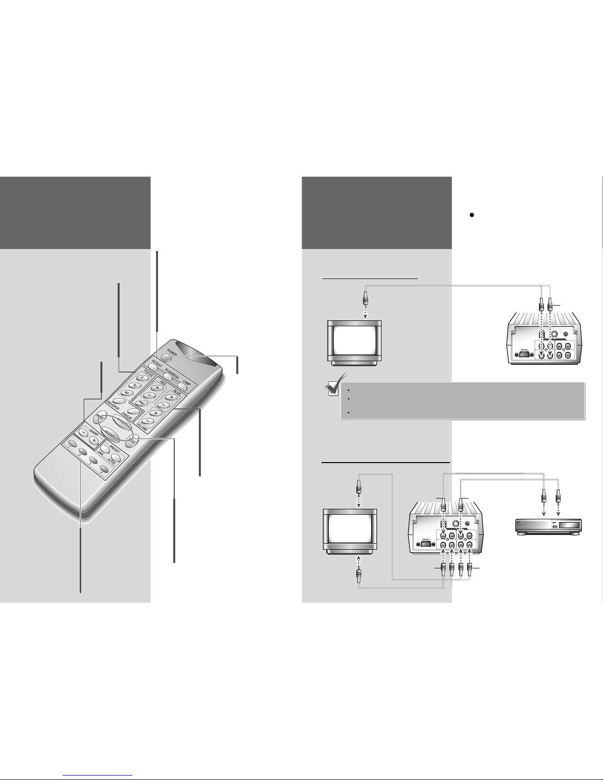
Remote Controller
Focus F/N button
Used to focus the image displayed on the
video presenter manally
AF button
Used to focus the image displayed on the
video presenter automatically
Reverse button
Used to put the image into reverse up/down
or right/left
Freeze button
Used to freeze the image on the screen
SHARP + button
Used to see the image sharper
SHARP - button
Used to see the image duller
Volume +/- button
Used to increase or decrease the
volume of microphone
AWC button
Used to adjust the screen color (white
balance) automatically
RED+/-button and BLUE +/-button
Used to increase the red or blue color
factor
INT/EXT button
Used to select internal Image or external Image
Internal (INT): To see the image on this presenter
External (EXT): To see the image sent from another AV
equipment through monitor (if connected to this
presenter)
POSI/NEGA button
Positive (POSI): To see the general state or positive film
Negative (NEGA): To see the negative film
Lamp button
Used to turn the head lamp on and off
WIDE button
Used to reduce the image size of an object
TELE button
Used to enlarge the image size of an object
BRIGHT + button
Used to make the screen brighter
BRIGHT - button
Used to make the screen darker
Preset button
Used to save the current status (Zoom,
Focus, Lamp, Color etc).
When you use the video presenter on
another place, you need not to repeat
the same procedures but the saved
status will be automatically set only
by pressing the “Active” button.
Select the button (1~4) and press it
within 4 seconds after pressing
“Save/Active” button.
NAME AND FUNCTION
OF PART
Power button
Used to turn power on
and off
1
2
1
2
1
2
1
2
POWER IN
S-VIDEO OUT
DC12V IN
VIDEO
AUDIO
IN IN
OUT OUT
1
2
1
2
1
2
1
2
POWER IN
S-VIDEO OUT
DC12V IN
VIDEO
AUDIO
IN IN
OUT OUT
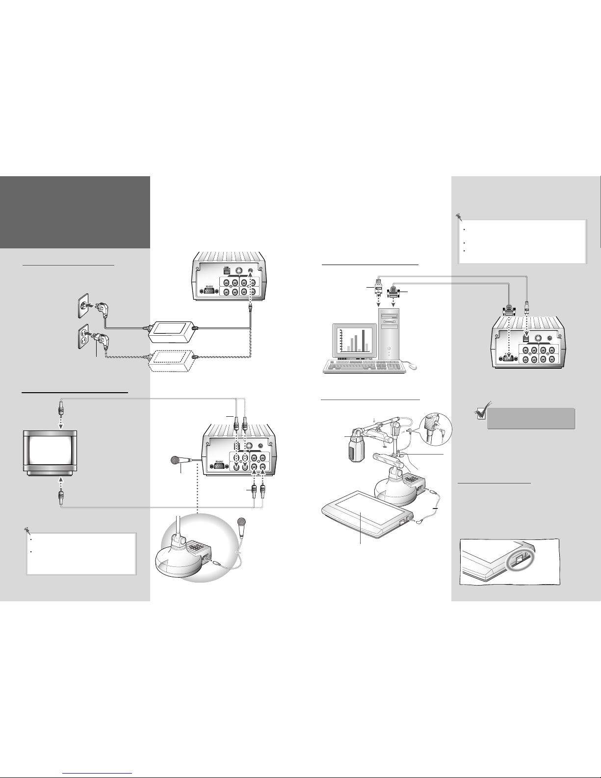
CONNECTION
Use the white plug to connect audio
terminal, and the yellow (or red) plug
to connect video terminal.
To TV or Monitor
You may use either 'Video OUT 1' or 'Video OUT 2' jack.
Connect 'S-video OUT' terminal when you have a TV with S-Video terminal. If 'S-Video OUT' terminal is
used, you can get more clear image, but the signal from external AV source will not be available.
Connect 'RF output terminal' to TV with only RF terminal.
To TV or Monitor and External AV Device
TV, Monitor,
LCD Projector
to video input terminal
Video Presenter
Yellow
AV Device (VTR, Camcorder)
White
Yellow
White
Yellow
TV, Monitor,
LCD Projector
Video Presenter
to video
input
terminal
to video
output
terminal
to audio
input
terminal
to audio
output
terminal
Connecting to PC
Head lamp
How to install the Head Lamp
It is nipper shaped. Clip it
where you want.
Lightbox
How to use
You can switch on and off the Lightbox by using the
power switch at the side.
How to install the Lightbox
You can use it to see the slides or negative films.
Pay attention not to scratch. You cannot see the clear
image if there is scar.
13
When the light of head lamp is projected
to the script, it means that the head
lamp is installed in this place.
1
2
1
2
1
2
1
2
POWER IN
S-VIDEO OUT
DC12V IN
VIDEO
AUDIO
IN IN
OUT OUT
RS-232C
Connected with
RS-232C Port in
PC
Personal
Computer
USB Connected
with USB Port in
PC
USB Cable
RS-232C Cable
Video Presenter
After connecting to PC properly, install the USB
Device Driver and SVP-5300 Capture program.
The programs ave supplied with presenter.
RS-232C Communication cable is not supplied with
this product.
CONNECTION
1
2
1
2
1
2
1
2
POWER IN
S-VIDEO OUT
DC12V IN
VIDEO
AUDIO
IN IN
OUT OUT
To Microphone
Video Presenter
To Video Input terminal
To Audio Input terminal
Microphone(ф6.3)
Yellow
White
Microphone is not supplied with this product.
Please purchase a microphone.
If the microphone is connected, the presenter
can send the image and sound at the same
time so it is more convenient to use in
presentation or exhibition.
1
2
1
2
1
2
1
2
POWER IN
S-VIDEO OUT
DC12V IN
VIDEO
AUDIO
IN IN
OUT OUT
To Power Outlet
12
Video Presenter
Adapter
This video presenter can operate on free
voltage (100~240V).
Use a converter for 110V
fixing into the power cord
To use 110V
To use 220V
TV, Monitor,
LCD Projector
 Loading...