

SAMSUNG SV-DVD6E, SV-DVD3E, SV-DVD3BE Service Manual Disassembly & Reassembly
Samsung Electronics
3-1
3. Disassembly and Reassembly
3-1 Cabinet and PCB
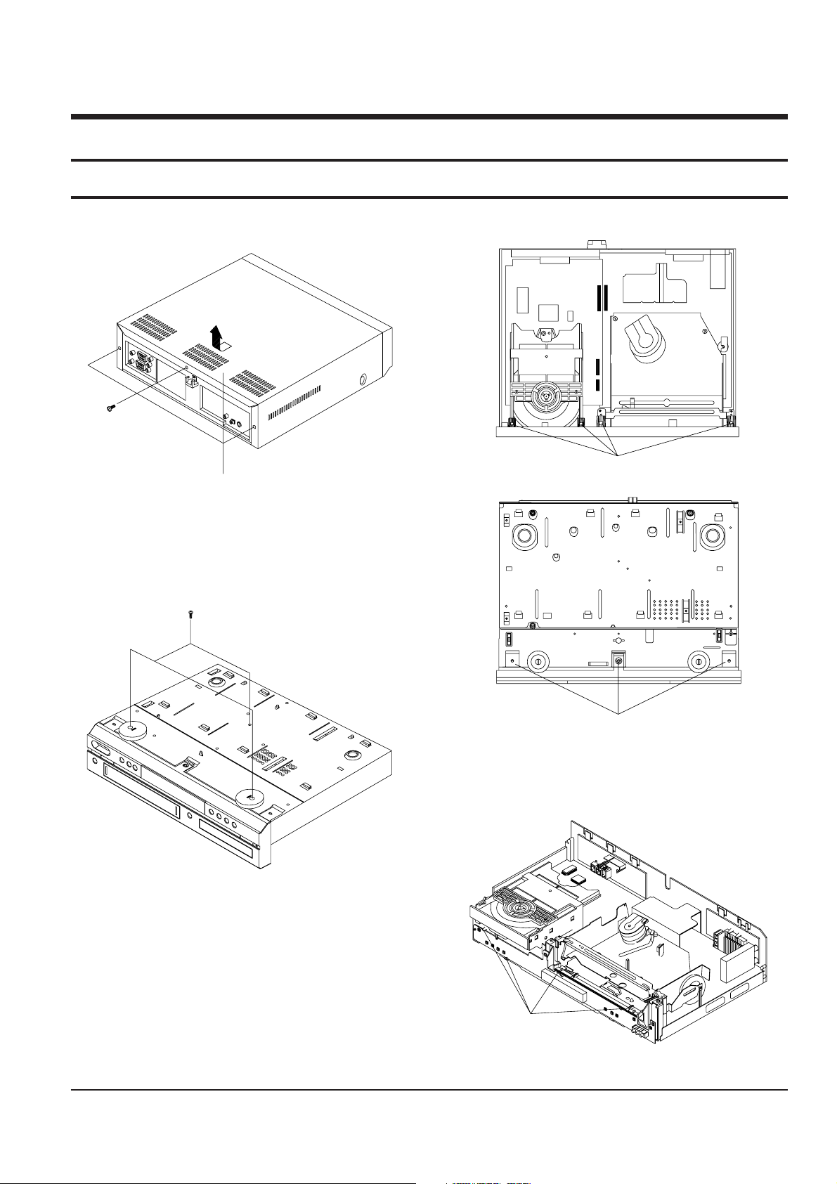
3-1-1 Cabinet Top Removal
Lift up the Cabinet Top in the direction of arrow.
ΠREMOVE
3 SCREWS
Fig. 3-1 Cabinet Top Removal
3-1-3 Ass’y Front Panel Removal
ΠRELEASE 4 HOOKS
´ RELEASE 3 HOOKS
(Top View)
(Bottom View)
Fig. 3-3 Ass’y Front Panel Removal
3-1-2 Bottom Cover Removal
ΠREMOVE 3 SCREWS
Fig. 3-2 Bottom Cover Removal
3-1-4 Function-Timer PCB Removal
ΠRELEASE 4 HOOKS
Fig. 3-4 Function-Timer PCB Removal
3-2
Disassembly and Reassembly
Samsung Electronics
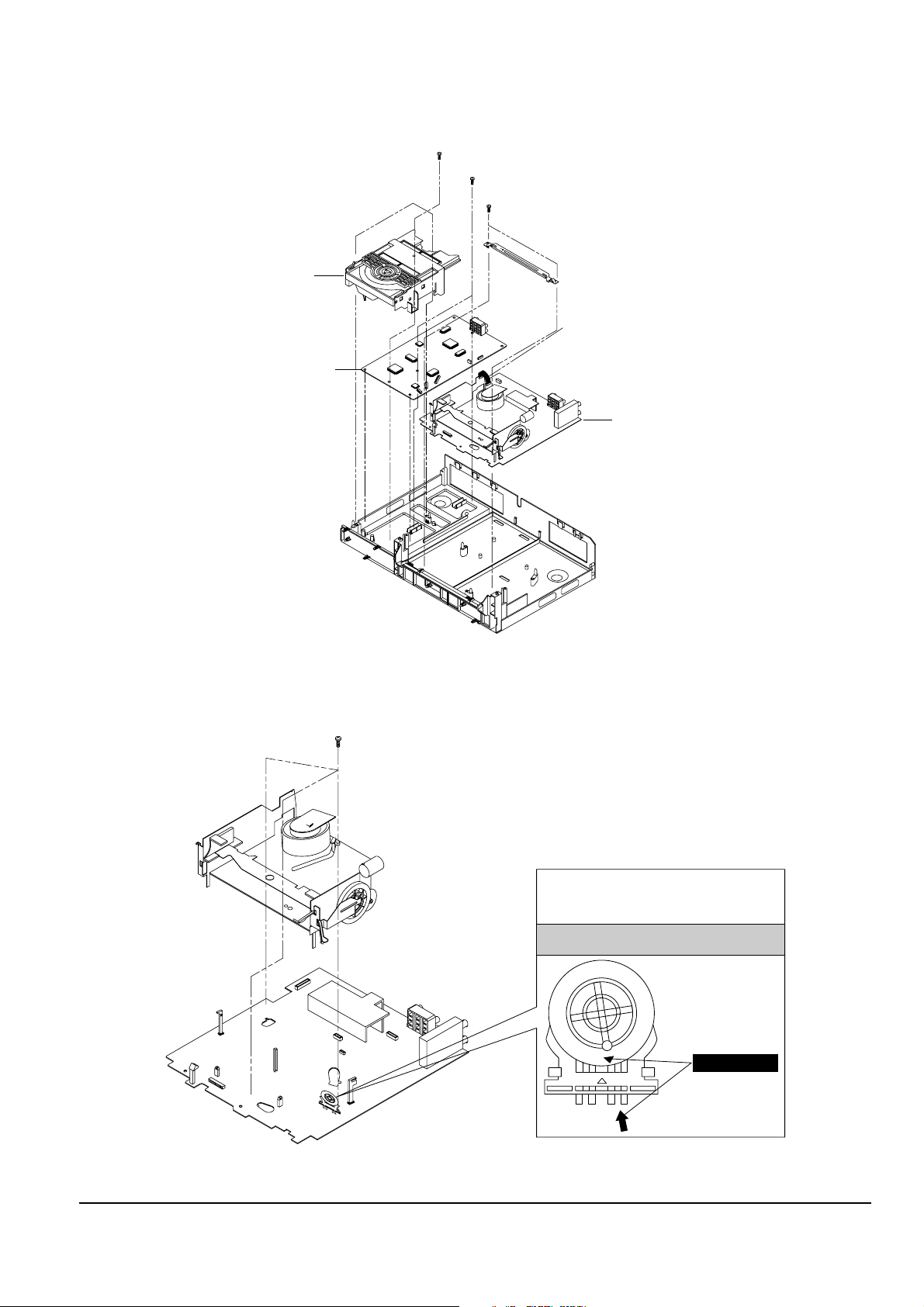
3-1-5 Chassis Removal
¨ REMOVE 3 SCREWS
´ REMOVE 2 SCREWS
ˇ REMOVE 2 SCREWS
ΠREMOVE CONNECTORS
DVD MAIN PCB
DVD-DECK
VCR MAIN PCB
Fig. 3-5 Chassis Removal
3-1-6 VCR Main PCB Removal
ΠREMOVE 3 SCREWS
MODE SWITCH
When installing the ass’y full deck on the Main PCB,
be sure to align the assembly point of mode switch.
ASSEMBLY POINT
Fig. 3-6 VCR Main PCB Removal
Disassembly and Reassembly
3-3
Samsung Electronics
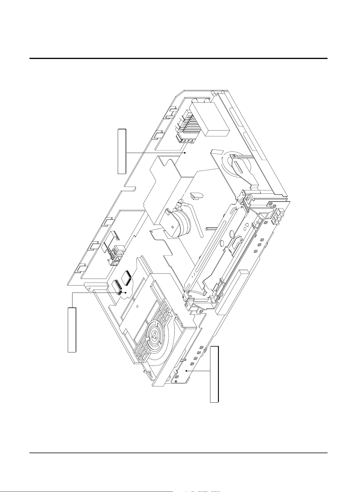
3-2 Circuit Board Locations
VCR MAIN PCB
DVD MAIN PCB
FUNCTION-TIMER PCB
Fig. 3-7 Circuit Board Locations
 Loading...