

Samsung SV-DVD50 Service Manual

DVD-VCR COMBINATION
Chassis : Diva
SV-DVD50
SERVICE
1. Precautions
2. Alignment and Adjustment
3. Exploded Views and Parts List
4. Electrical Parts List
5. Block Diagram
6. Schematic Diagrams
Manual
DVD-VCR COMBINATION CONTENTS
SERVICE MANUAL SV-DVD50
EJECT
STANDBY/ON
DVD
PROG
VCR
AUX
ELECTRONICS
© Samsung Electronics Co., Ltd. MAR. 2003
Printed in Korea
AK82-00329A
If you want to know additional information which is not included on this Service Manual, please refer to the
SV-DVD50 Training Manual (AK82-00330A).
IMPORTANT SERVICE GUIDE
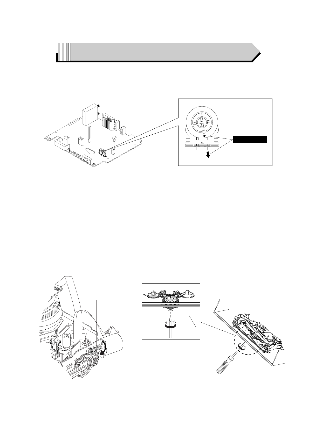
◆ MODE SWITCH (PROGRAM SWITCH) ASSEMBLY POINT
1) When installing the ass’y deck on the Main PCB, be sure to align the assembly point of mode switch.
MAIN PCB
ASSEMBLY POINT
Fig. 1
◆ HOW TO EJECT THE CASSETTE TAPE
(If the tape is stuck in the unit)
1) Turn the Gear Worm Πclockwise in the direction of arrow with screwdriver. (See Fig. 2)
(Other method ; Remove the screw of Motor Load Ass’y, Separate the Motor Load Ass’y)
2) When Slider S, T are approach the unloading position, rotate holder Clutch counterclockwise after inserting screwdriver in the
frame’s bottom hole in order to wind the unwound tape. (Refer to Fig. 3)
(If you rotate Gear Worm Πcontinuously when tape is in state of unwinding, you may cause tape contamination by grease and
tape damage. Be sure to wind the unwound tape in the state of set horizontally.)
3) Rotate Gear Worm Πclockwise using screw driver again up to the state of eject mode and then pick out the tape. (Refer to Fig. 2)
Fig. 2 Fig. 3
ΠGEAR WORM
FRAME
Samsung Electronics 1-1
1. Precautions
1-1 Safety Precautions
1) Before returning an instrument to the customer,
always make a safety check of the entire instrument,
including, but not limited to, the following items:
(1) Be sure that no built-in protective devices are
defective or have been defeated during servicing.
(1)Protective shields are provided to protect both
the technician and the customer. Correctly replace
all missing protective shields, including any
removed for servicing convenience.
(2)When reinstalling the chassis and/or other assembly in the cabinet, be sure to put back in place
all protective devices, including, but not limited to,
nonmetallic control knobs, insulating fish papers,
adjustment and compartment covers/shields, and
isolation resistor/capacitor networks. Do not operate this instrument or permit it to be operated without all protective devices correctly installed and
functioning.
(2) Be sure that there are no cabinet openings through
which adults or children might be able to insert
their fingers and contact a hazardous voltage. Such
openings include, but are not limited to, excessively wide cabinet ventilation slots, and an improperly fitted and/or incorrectly secured cabinet back
cover.
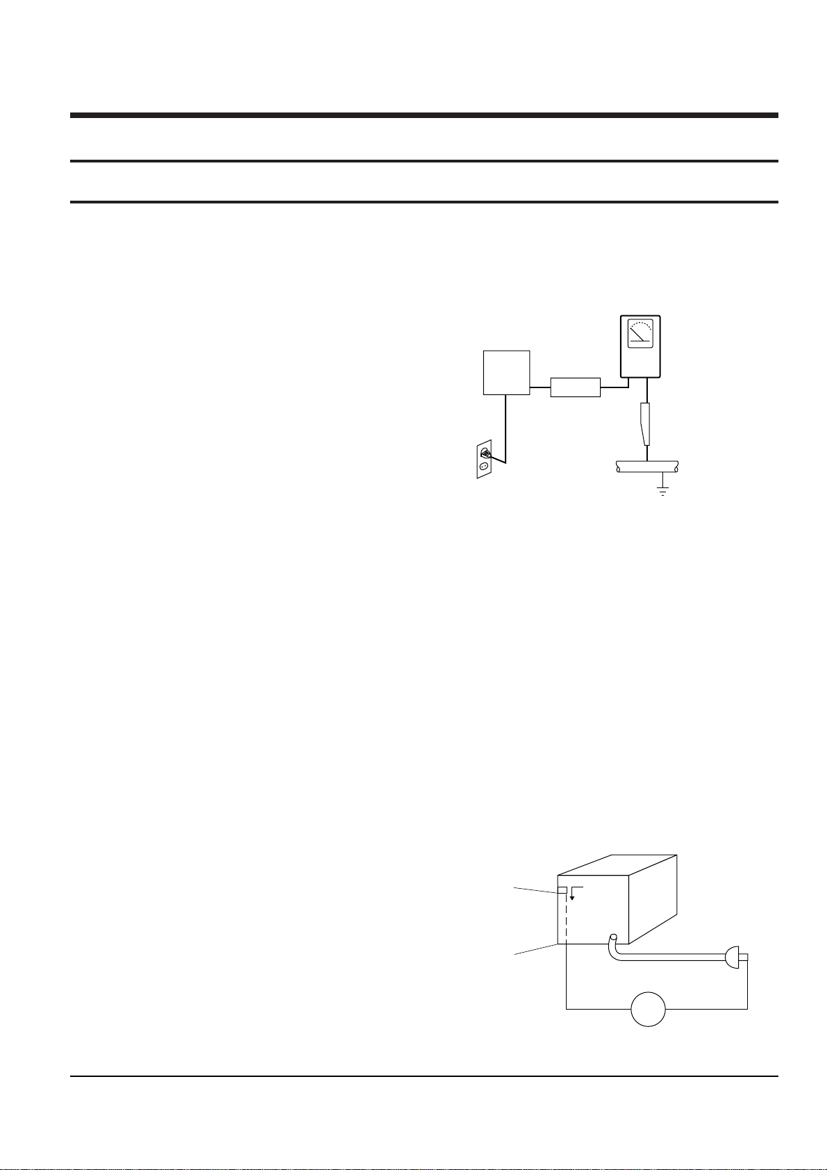
(3) Leakage Current Hot Check-With the instrument
completely reassembled, plug the AC line cord
directly into a 120V AC outlet. (Do not use an isolation transformer during this test.) Use a leakage
current tester or a metering system that complies
with American National Standards institute (ANSI)
C101.1 Leakage Current for Appliances and
Underwriters Laboratories (UL) 1270 (40.7). With
the instrument’s AC switch first in the ON position
and then in the OFF position, measure from a
known earth ground (metal water pipe, conduit,
etc.) to all exposed metal parts of the instrument
(antennas, handle brackets, metal cabinets, screwheads, metallic overlays, control shafts, etc.), especially any exposed metal parts that offer an electrical return path to the chassis.
Any current measured must not exceed 0.5mA.
Reverse the instrument power cord plug in the outlet and repeat the test. See Fig. 1-1.
Any measurements not within the limits specified
herein indicate a potential shock hazard that must
be eliminated before returning the instrument to
the customer.
Fig. 1-1 AC Leakage Test
(4) Insulation Resistance Test Cold Check-(1) Unplug
the power supply cord and connect a jumper wire
between the two prongs of the plug. (2) Turn on the
power switch of the instrument. (3) Measure the
resistance with an ohmmeter between the
jumpered AC plug and all exposed metallic cabinet
parts on the instrument, such as screwheads,
antenna, control shafts, handle brackets, etc. When
an exposed metallic part has a return path to the
chassis, the reading should be between 1 and 5.2
megohm. When there is no return path to the chassis, the reading must be infinite. If the reading is
not within the limits specified, there is the possibility of a shock hazard, and the instrument must be
repared and rechecked before it is returned to the
customer. See Fig. 1-2.
Fig. 1-2 Insulation Resistance Test
DEVICE
UNDER
TEST
(READING SHOULD
NOT BE ABOVE
0.5mA)
LEAKAGE
CURRENT
TESTER
EARTH
GROUND
TEST ALL
EXPOSED METER
SURFACES
ALSO TEST WITH
PLUG REVERSED
(USING AC ADAPTER
PLUG AS REQUIRED)
2-WIRE CORD
Antenna
Terminal
Exposed
Metal Part
ohm
ohmmeter

Precautions
1-2 Samsung Electronics
2) Read and comply with all caution and safety related notes on or inside the cabinet, or on the chassis.
3) Design Alteration Warning-Do not alter or add to
the mechanical or electrical design of this instrument. Design alterations and additions, including
but not limited to, circuit modifications and the
addition of items such as auxiliary audio output
connections, might alter the safety characteristics of
this instrument and create a hazard to the user. Any
design alterations or additions will make you, the
servicer, responsible for personal injury or property
damage resulting therefrom.
4) Observe original lead dress. Take extra care to
assure correct lead dress in the following areas:
(1) near sharp edges, (2) near thermally hot parts (be
sure that leads and components do not touch thermally hot parts), (3) the AC supply, (4) high voltage,
and (5) antenna wiring. Always inspect in all areas
for pinched, out-of-place, or frayed wiring, Do not
change spacing between a component and the
printed-circuit board. Check the AC power cord for
damage.
5) Components, parts, and/or wiring that appear to
have overheated or that are otherwise damaged
should be replaced with components, parts and/ or
wiring that meet original specifications.
Additionally, determine the cause of overheating
and/or damage and, if necessary, take corrective
action to remove any potential safety hazard.
6) Product Safety Notice-Some electrical and mechanical parts have special safety-related characteristics
which are often not evident from visual inspection,
nor can the protection they give necessarily be
obtained by replacing them with components rated
for higher voltage, wattage, etc. Parts that have special safety characteristics are identified by shading,
an ( )or a ( )on schematics and parts lists. Use
of a substitute replacement that does not have the
same safety characteristics as the recommended
replacement part might create shock, fire and/or
other hazards. Product safety is under review continuously and new instructions are issued whenever appropriate.

Precautions
Samsung Electronics 1-3
1-2 Servicing Precautions
CAUTION : Before servicing units covered by this
service manual and its supplements, read and follow
the Safety Precautions section of this manual.
Note : If unforseen circument create conflict between
the following servicing precautions and any of the
safety precautions, always follow the safety precautions. Remember: Safety First.
1-2-1 General Servicing Precautions
(1) a. Always unplug the instrument’s AC power cord
from the AC power source before (1) re-moving
or reinstalling any component, circuit board,
module or any other instrument assembly, (2)
disconnecting any instrument electrical plug or
other electrical connection, (3) connecting a test
substitute in parallel with an electrolytic capacitor in the instrument.
b. Do not defeat any plug/socket B+ voltage inter-
locks with which instruments covered by this
service manual might be equipped.
c. Do not apply AC power to this instrument and
/or any of its electrical assemblies unless all
solid-state device heat sinks are correctly installed.
d. Always connect a test instrument’s ground lead
to the instrument chassis ground before connecting the test instrument positive lead. Always
remove the test instrument ground lead last.
Note : Refer to the Safety Precautions section ground
lead last.
(2) The service precautions are indicated or printed on
the cabinet, chassis or components. When servicing, follow the printed or indicated service precautions and service materials.
(3) The components used in the unit have a specified
flame resistance and dielectric strength.
When replacing components, use components
which have the same ratings. Components ientified
by shading, by( ) or by ( ) in the circuit diagram
are important for safety or for the characteristics of
the unit. Always replace them with the exact
replacement components.
(4) An insulation tube or tape is sometimes used and
some components are raised above the printed
wiring board for safety. The internal wiring is
sometimes clamped to prevent contact with heating components. Install such elements as they
were.
(5) After servicing, always check that the removed
screws, components, and wiring have been installed correctly and that the portion around the
serviced part has not been damaged and so on.
Further, check the insulation between the blades of
the attachment plug and accessible conductive
parts.
1-2-2 Insulation Checking Procedure
Disconnect the attachment plug from the AC outlet
and turn the power ON. Connect the insulation resistance meter (500V) to the blades of the attachment
plug. The insulation resistance between each blade of
the attachment plug and accessible conductive
parts(see note) should be more than 1 Megohm.
Note : Accessible conductive parts include metal panels, input terminals, earphone jacks, etc.

Precautions
1-4 Samsung Electronics
1-3 ESD Precautions
Electrostatically Sensitive Devices (ESD)
Some semiconductor (solid state) devices can be damaged easily by static electricity.
Such components commonly are called Electrostatically Sensitive Devices(ESD). Examples of typical ESD
devices are integrated circuits and some field-effect
transistors and semiconductor chip components. The
following techniques should be used to help reduce
the incidence of component damage caused by static
electricity.
(1) Immediately before handling any semiconductor
component or semiconductor-equipped assembly,
drain off any electrostatic charge on your body by
touching a known earth ground. Alternatively,
obtain and wear a commercially available discharging wrist strap device, which should be
removed for potential shock reasons prior to applying power to the unit under test.
(2) After removing an electrical assembly equipped
with ESD devices, place the assembly on a conductive surface such as aluminum foil, to prevent electrostatic charge buildup or exposure of the assembly.
(3) Use only a grounded-tip soldering iron to solder or
unsolder ESD devices.
(4) Use only an anti-static solder removal devices.
Some solder removal devices not classified as
“anti-static” can generate electrical charges sufficient to damage ESD devices.
(5) Do not use freon-propelled chemicals. These can
generate electrical charges sufficient to damage
ESD devices.
(6) Do not remove a replacement ESD device from its
protective package until immediately before your
are ready to install it.(Most replacement ESD
devices are packaged with leads electrically shorted together by conductive foam, aluminum foil or
comparable conductive materials).
(7) Immediately before removing the protective ma-
terials from the leads of a replacement ESD device,
touch the protective material to the chassis or circuit assembly into which the device will be
installed.
CAUTION : Be sure no power is applied to the chassis or circuit, and observe all other safety precautions.
(8) Minimize bodily motions when handling unpack-
aged replacement ESD devices. (Otherwise harmless motion such as the brushing together of your
clothes fabric or the lifting of your foot from a carpeted floor can generate static electricity sufficient
to damage an ESD device).
Precautions
Samsung Electronics 1-5
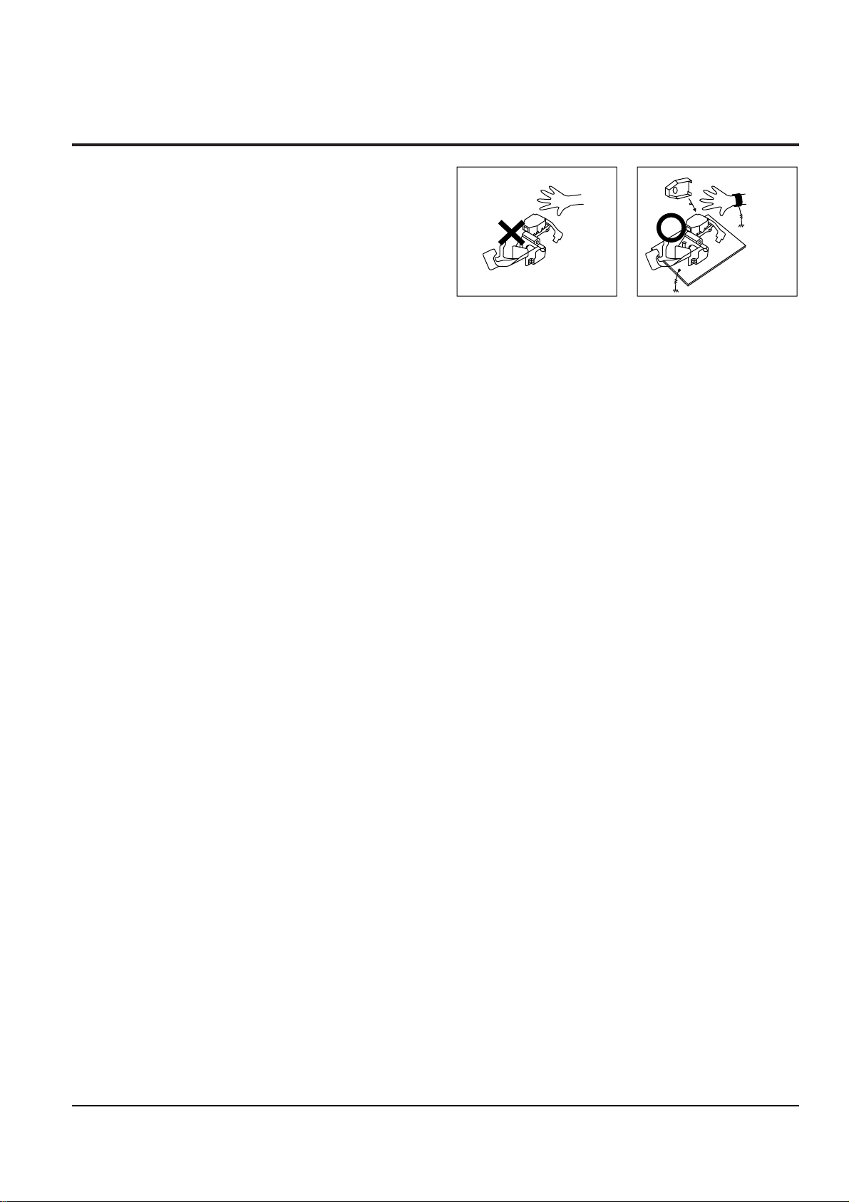
1-4 Handling the optical pick-up
The laser diode in the optical pick up may suffer electrostatic breakdown because of potential static electricity from clothing and your body.
The following method is recommended.
(1) Place a conductive sheet on the work bench (The
black sheet used for wrapping repair parts.)
(2) Place the set on the conductive sheet so that the
chassis is grounded to the sheet.
(3) Place your hands on the conductive sheet(This
gives them the same ground as the sheet.)
(4) Remove the optical pick up block
(5) Perform work on top of the conductive sheet. Be
careful not to let your clothes or any other static
sources to touch the unit.
◆ Be sure to put on a wrist strap grounded to the
sheet.
◆ Be sure to lay a conductive sheet made of copper
etc. Which is grounded to the table.
Fig.1-3
(6) Short the short terminal on the PCB, which is in-
side the Pick-Up ASS’Y, before replacing the PickUp. (The short terminal is shorted when the PickUp Ass’y is being lifted or moved.)
(7) After replacing the Pick-up, open the short termi-
nal on the PCB.
THE UNIT
WRIST-STRAP
FOR GROUNDING
1M
1M
CONDUCTIVE SHEET
Precautions
1-6 Samsung Electronics
1-5 Pick-up disassembly and reassembly
1-5-1 Disassembly
1) Remove the power cord.
2) Disassemble the Deck-Assy.
3) Make solder land 2 points short on Pick-up.
(See Fig. 1-4)
4) Disassembly the Pick-up.
1-5-2 Assembly
1) Replace the Pick-up.
2) Remove the soldering 2 points on Pick-up.
3) Reassemble the Deck-Assy.
PICK-UP ASS'Y
SOLDER LAND 2 POINTS SHORT
Note : If the assembly and disassembly are not done in correct sequence, the Pick-up may be damaged.
Fig. 1-4
Samsung Electronics
2-1
2. Alignment and Adjustments
2-1 VCR Adjustment
1) X-Point (Tracking center) adjustment, “Head switching adjustment” and “NVRAM option setting” can be adjusted with remote control.
2) When replacing the Main PCB Micom (IC601) and NVRAM (IC605 ; EEPROM) be sure to adjust the “Head switching adjustment” and
“NVRAM option setting”.
3) When replacing the cylinder ass’y, be sure to adjust the “X-Point” and “Head switching adjustment”.
4) How to adjustment.
- Intermittently short-circuit the Test Point on Main PCB with pincers to the adjustment mode.
- If the corresponding adjustment button is pressed, the adjustment is performed automatically.
- If the adjustment is completrd, be sure to turn the power off.
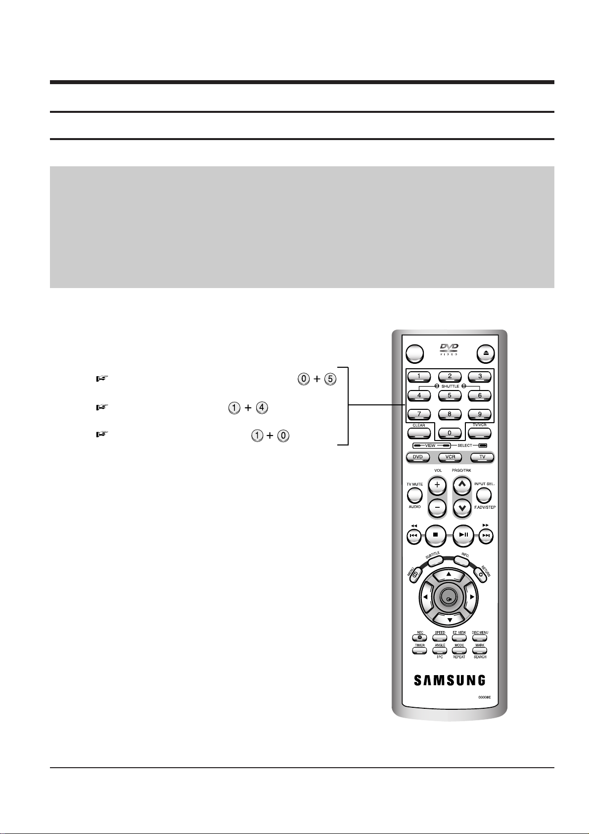
2-1-1(a) Location of adjustment button of remote control
Fig. 2-1
OPEN/CLOSE
STANDBY/ON
OK
X-Point (Tracking Center) Adjustment ;
Head Switching Adjustment ;
NVRAM Option Setting ;
2-1-1 Reference
2-2
Alignment and Adjustments
Samsung Electronics
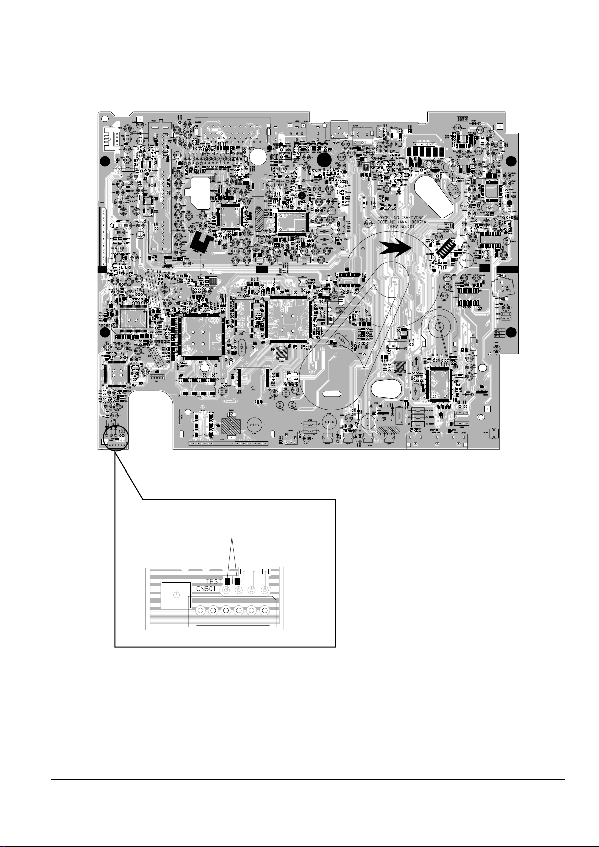
2-1-1(b) TEST location for adjustment mode setting
Fig. 2-2 Main PCB (Top View)
Short-Circuit for few seconds and release.
(Just one time)
Alignment and Adjustments
2-3
Samsung Electronics
2-1-2 Head Switching Point Adjustment
1) Playback the alignment tape.
2) Intermittently short-circuit the two Test Points on Main PCB while setting the adjustment mode. (See Fig. 2-2)
3) Press the “1, 0” buttons; remote control adjustment operates automatically. (See Fig. 2-1)
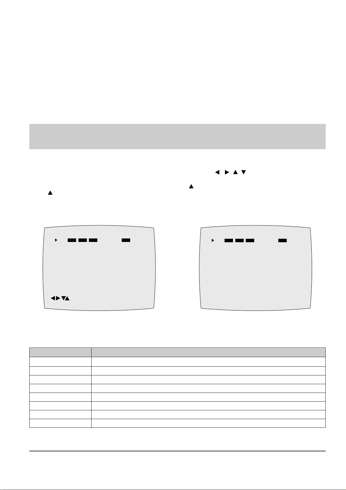
2-1-3 NVRAM Option Setting
1) Intermittently short-circuit the two Test Points on Main PCB. (See Fig. 2-2)
2)
Press the “1, 4” buttons on the remote control. The option setting is appears. (See Fig. 2-3)
3)
Select the option number (See table 2-1) of corresponding model with “ , , , ” buttons on the
remote control.
4) After selecting the option number is completed, press the “ ” button of remote control.
(If “ ” button is pressed, the selected number is changescolor. ; See Fig. 2-4)
5) Press the “ENTER” button of remote control again to store the option number.
6) Turn the Power off.
1) NVRAM Option is adjusted in the factory.
2) In case Main PCB Micom (IC601) and NVRAM (IC605 ; EEPROM) are replaced, be sure to set the corresponding option number of the
required model. (If the option is not set, the unit will operate.)
<Table 2-1 NVRAM Option Table>
CNG : OK SAVE : RETURN
01 02 03 04 05 06 07 08
09 10 11 12 13 14 15 16
17 18 19 20 21 22 23 24
25 26 27 28 29 30 31 32
33 34 35 36 37 38 39 40
41 42 43 44 45 46 47 48
49 50 51 52 53 54 55 56
57 58 59 60 61 62 63 64
65 66 67 68 69 70 71 72
Fig. 2-3
MODEL OPTION NUMBERS
SV-DVD50/XEF 2, 4, 5, 6, 7, 8, 9, 10, 11, 12, 13, 15, 20, 21, 26, 32, 33, 34, 35, 36, 38, 40, 45, 47, 61, 63, 65, 69
SV-DVD50/XEU 3, 4, 5, 6, 7, 8, 9, 10, 11, 12, 13, 15, 27, 32, 34, 38, 40, 41, 45, 47, 61, 63, 65, 69
SV-DVD50/XEUI 3, 4, 5, 6, 7, 8, 9, 10, 11, 12, 13, 15, 25, 26, 32, 34, 38, 40, 43, 45, 47, 61, 63, 65, 69
SV-DVD50/XEG, XET 2, 4, 5, 6, 7, 9, 10, 11, 12, 13, 15, 32, 34, 36, 38, 40, 42, 45, 47, 61, 63, 65, 69, 72
SV-DVD50/XEC, XEE, XEN 2, 4, 5, 6, 7, 8, 9, 10, 11, 12, 13, 15, 32, 34, 36, 38, 40, 42, 45, 47, 61, 63, 65, 69, 72
SV-DVD50/XEB 2, 4, 5, 6, 7, 8, 9, 10, 11, 12, 13, 15, 20, 21, 26, 32, 33, 34, 35, 36, 38, 40, 42, 45, 47, 61, 63, 65, 69, 72
SV-DVD50/EUR, XEO 2, 4, 6, 7, 8, 9, 10, 11, 12, 13, 15, 20, 32, 33, 34, 36, 38, 42, 45, 47, 61, 63, 65, 69, 72
SV-DVD50/XEV 2, 6, 7, 8, 9, 10, 11, 12, 13, 15, 20, 21, 32, 33, 34, 36, 37, 39, 42, 45, 47, 54, 61, 63, 65, 69, 70
Fig. 2-4
01 02 03 04 05 06 07 08
09 10 11 12 13 14 15 16
17 18 19 20 21 22 23 24
25 26 27 28 29 30 31 32
33 34 35 36 37 38 39 40
41 42 43 44 45 46 47 48
49 50 51 52 53 54 55 56
57 58 59 60 61 62 63 64
65 66 67 68 69 70 71 72
PLEASE WAIT
2-4
Alignment and Adjustments
Samsung Electronics
2-2 DVD Adjustment
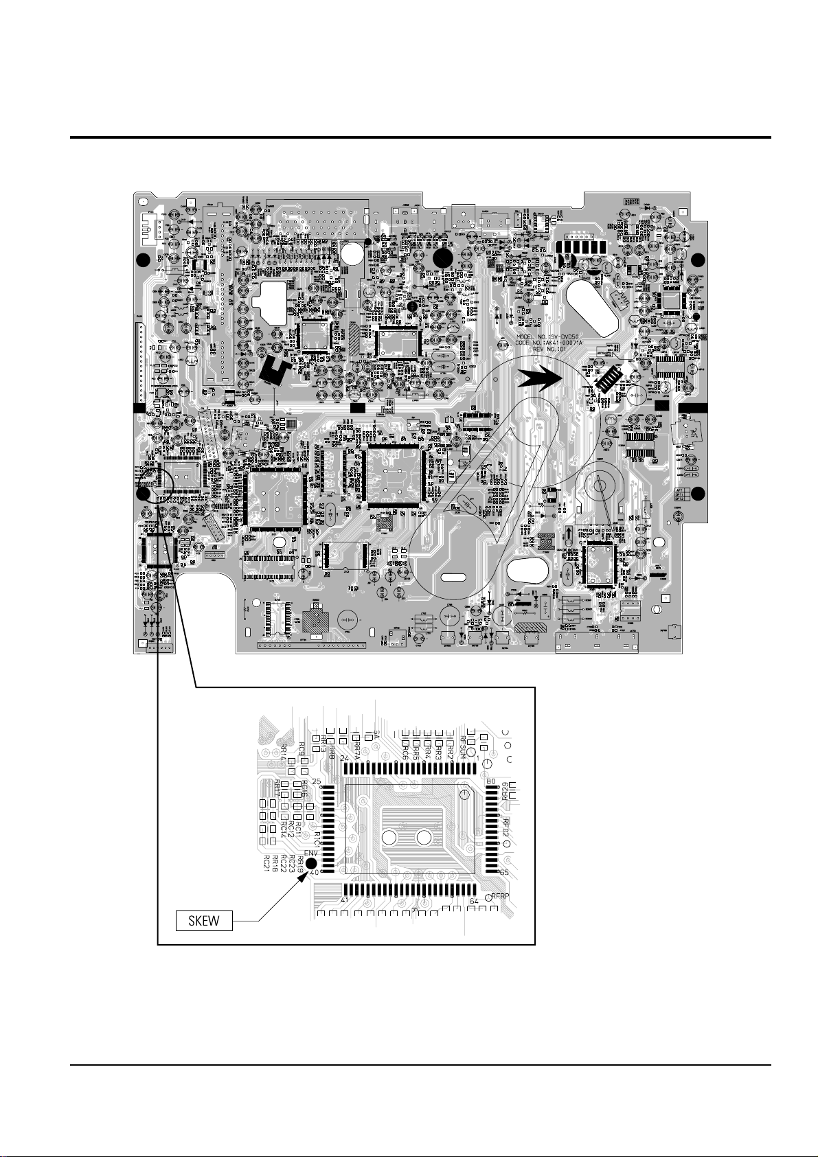
2-2-1 Location of Test Point
Fig. 2-5 Location of test Point (Main PCB - Top Side)
RIC1
RIC1
Alignment and Adjustments
2-5
Samsung Electronics
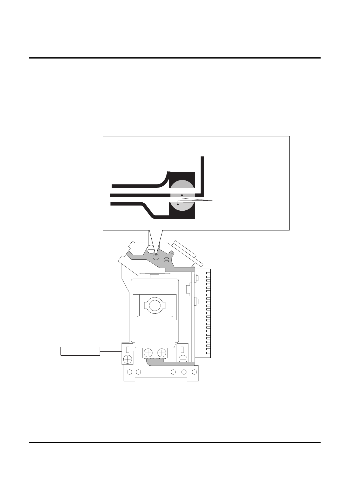
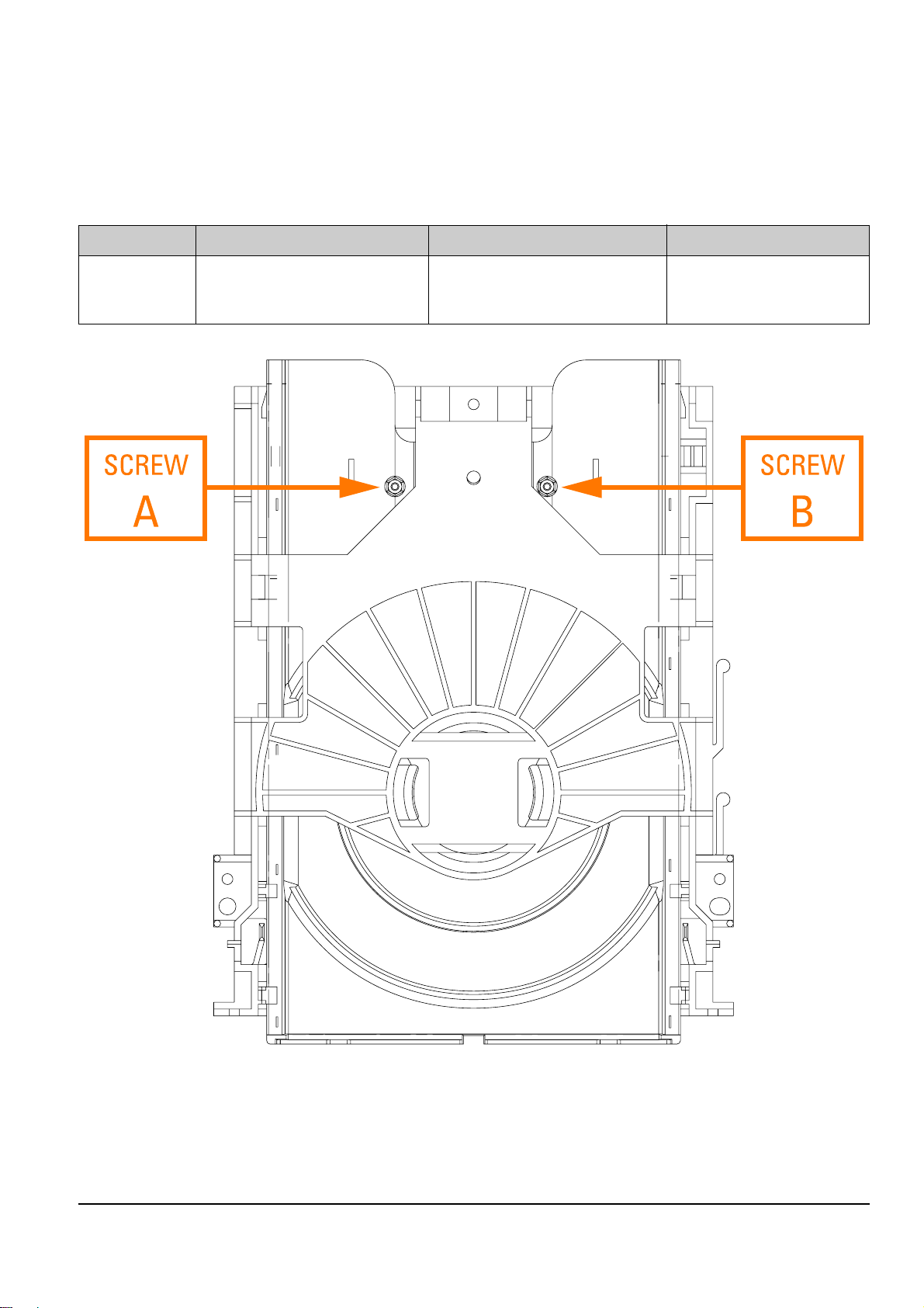
2-2-2(a) Adjustment Spec. and Test Point
2-2-2 Skew Adjustment
Test Disc Adjustment Spec. Test Point Adjustment Location
TDV-533 “ENV” Ass’y Deck - Top Side
Chapter 14 Flat Waveform (DVD Main PCB - Top Side) (See Fig. 2-6)
(See Fig. 2-5)
Fig. 2-6 Ass’y Deck (Top Side)
◆ Test Disc ; Service not Available
<Table 2-2>
2-6
Alignment and Adjustments
Samsung Electronics
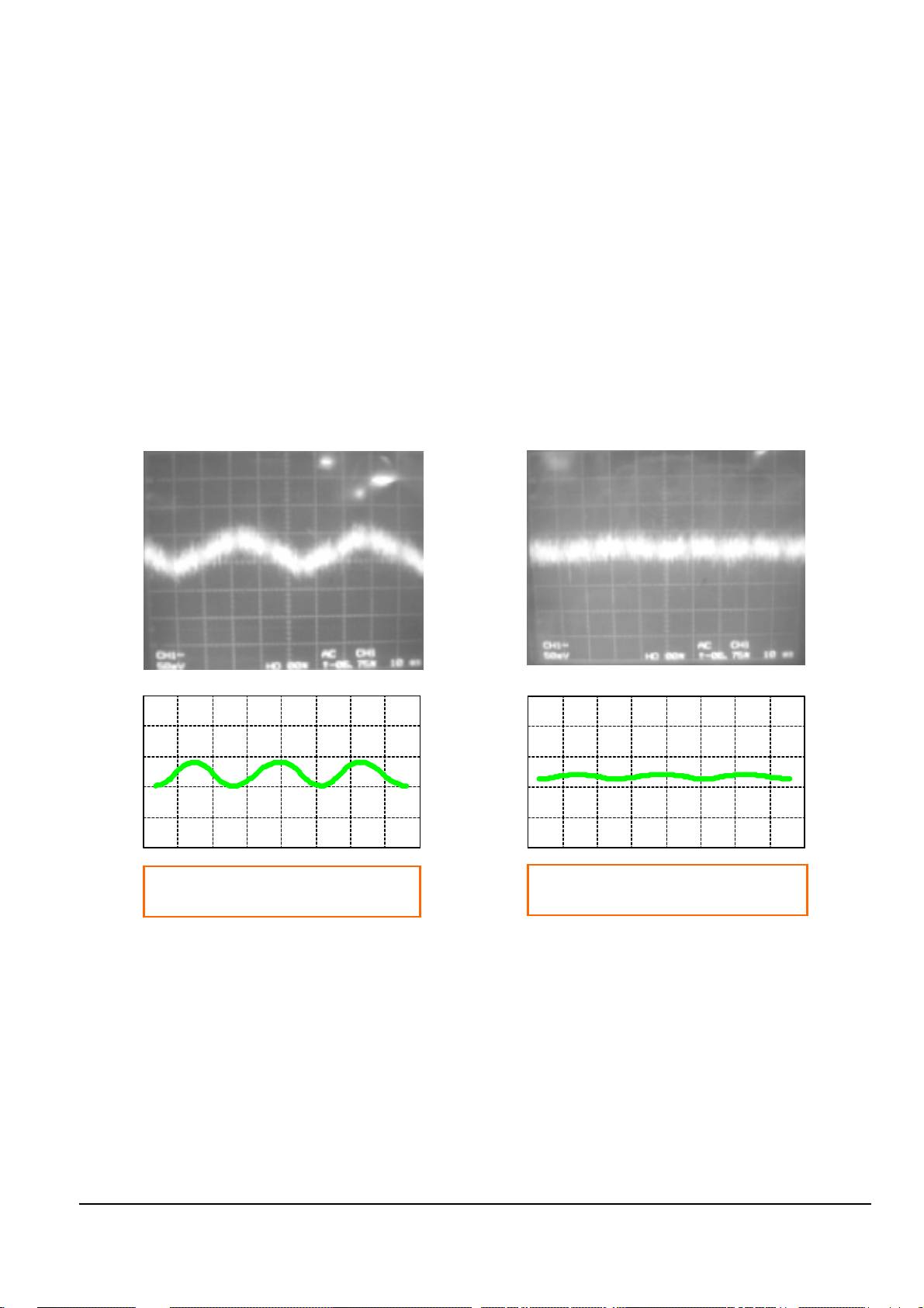
2-2-2(b) SKEW Adjustment Method
Needed to minimize the variations in Skew of the Pickup unit and to provide optimum match with the recorded
signal on the Disc.
1) Connect an Oscilloscope to the “ENV” Test Point (See Fig. 2-5).
2) Connect Power, Open the Tray and Play the TDV-533 Disc, Chapter 14.
◆ Set the Oscilloscope Range as follows :
(Voltage ; 50mV/Div., Frequency ; 10m Sec.)
3) Adjust the Screws “A” and “B” (See Fig. 2-6) using a Hex screwdriver until you obtain a Flat Waveform and
the picture is stable.
Then, go to Chapter 1 and make sure the Waveform is Flat here as well.
If not, you have to go back to Chapter 14 and adjust again.
If you cannot obtain a Flat waveform, then the unit is defective.
Note : The Deck must be in a horizontal position. Use both “A” and “B” screws to adjust.
Typical Waveform before Adjustment Waveform after Correct Adjustment
Fig. 2-7 Envelope Waveform
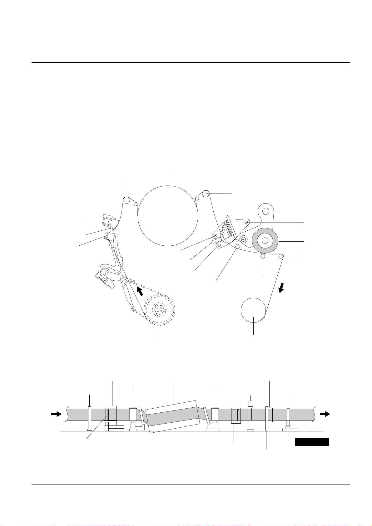
2-3 VCR Mechanical Adjustment
2-3-1 Tape Transport System and Adjustment Locations
The tape transport system has been adjusted precisely in the factory. Alignment is not necessary except for the
following :
1) Noise observed on the screen.
2) Tape damage.
3) Parts replacement in the tape transport system.
Lower flange height of tape guide is used as the reference for the transport adjustment.
To maintain the height of the tape guide and prevent damage, do not apply excessive force onto the main base.
Fig. 2-8 Location of Tape Transport Adjustment
Fig. 2-9 Tape Travel Diagram
CYLINDER ASS'Y
TAKE UP REEL DISK
#8 GUIDE POST
#9 GUIDE POST
SUPPLY REEL DISK
CAPSTAN
PINCH ROLLER
GUIDE ROLLER "T"
GUIDE ROLLER "S"
FULL ERASE HEAD
#3 GUIDE POST
TENSION POST
HEIGHT SCREW
TILT SCREW
X - POSITION
ADJUST SILT
AZIMUTH SCREW
POST TENSION
MAIN BASE
FE HEAD CYLINDER ASS'Y
PINCH ROLLER
GUIDE ROLLER "S" GUIDE ROLLER "T"
#8 GUIDE POST #9 GUIDE POST
CAPSTAN SHAFT
ACE HEAD
#3 GUIDE POST
Alignment and Adjustments
2-7
Samsung Electronics
2-8
Alignment and Adjustments
Samsung Electronics
2-3-2 Tape Transport System Adjustment
When parts are replaced, perform the required adjustments by referring to procedures for the tape transport
system. If there are any changes to the tape path, first run a T-120 tape and make sure excessive tape wrinkle does
not occur at the tape guides.
◆ If tape wrinkle is observed at the guide roller S, T, turn the guide roller S, T until wrinkle disappears.
◆ If the tape wrinkle is still observed at the tape guide, perform the tilt adjustment of the ACE head.
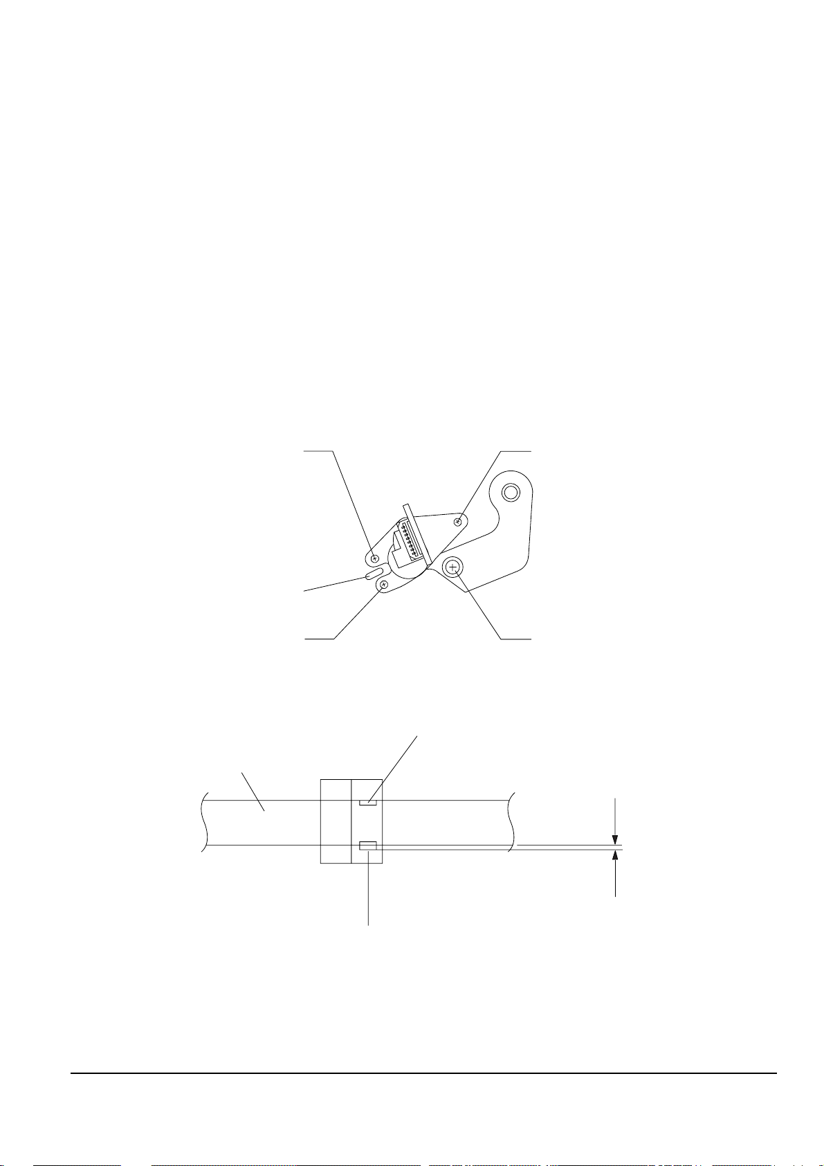
(1) ACE Head Assembly Adjustment
a. ACE HEAD HEIGHT ADJUSTMENT
1) Run the alignment tape (Color bar) in the playback mode.
2) Observe surface of the audio head using a dental mirror.
3) Turn screw (C) clockwise or counterclockwise until the gap of lower tape edge and the lower edge of the
control head is about 0.25mm. (Refer to Fig. 2-10 and 2-11)
Fig. 2-10 Location of ACE Head Adjustment Screw
Fig. 2-11 ACE Head Height Adjustment
SCREW (A)
TLIT ADJUST
X-POSITION
ADJUSTING SLIT
SCREW (C)
HEIGHT ADJUST
SCREW (D)
X-POSITION LOCKING
SCREW (B)
AZIMUTH ADJUST
0 ~ 0 .25 mm
AUDIO HEAD
VIDEO HEAD
CONTROL HEAD
Alignment and Adjustments
2-9
Samsung Electronics
b. ACE HEAD TILT ADJUSTMENT
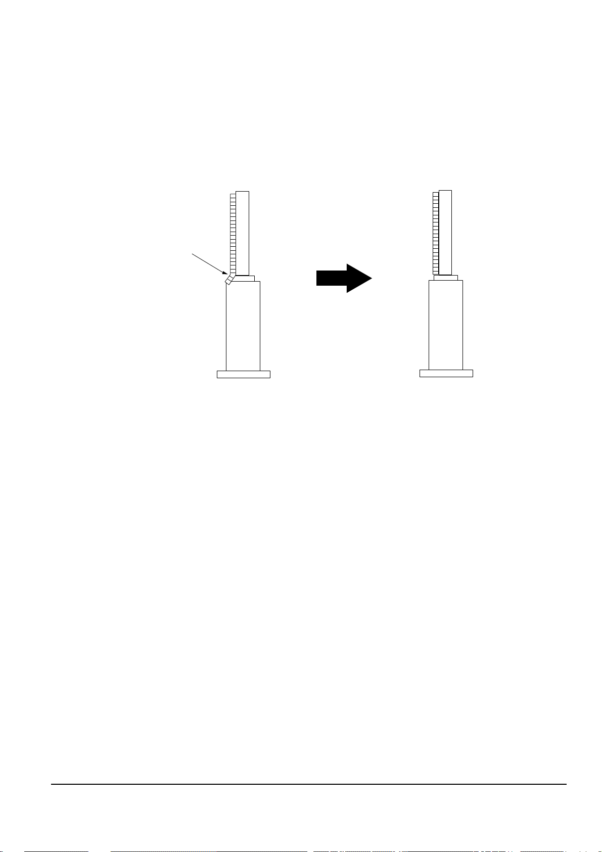
1) Playback a blank tape and observe the position of the tape at the lower flange of tape guide.
2) Confirm that there is no curl or wrinkle at the lower flange of tape guide as shown in Fig. 2-12 (B).
3) If a curl or wrinkle of the tape occurs, slightly
turn the screw (A) tilt adjust on the ACE head ass’y.
4) Reconfirm the ACE head height.
Fig. 2-12 Tape Guide Check
c. AUDIO AZIMUTH ADJUSTMENT
1) Load alignment tape (Mono scope) and playback the 7KHz signal.
2) Connect channel-1 scope probe to audio output.
3) Adjust screw (B) to achieve maximum audio level. (See Fig. 2-10)
(A) (B)
(BAD)
WRINKLE
(GOOD)
2-10
Alignment and Adjustments
Samsung Electronics
d. ACE HEAD POSITION (X-POINT) ADJUSTMENT
1) Playback the alignment tape (Color bar)
2) Intermittently short-circuit the two Test Points on Main PCB. (See Fig. 2-2)
3) Press the “0, 5” remote control buttons, then adjustment is operates automatically. (See Fig. 2-1)
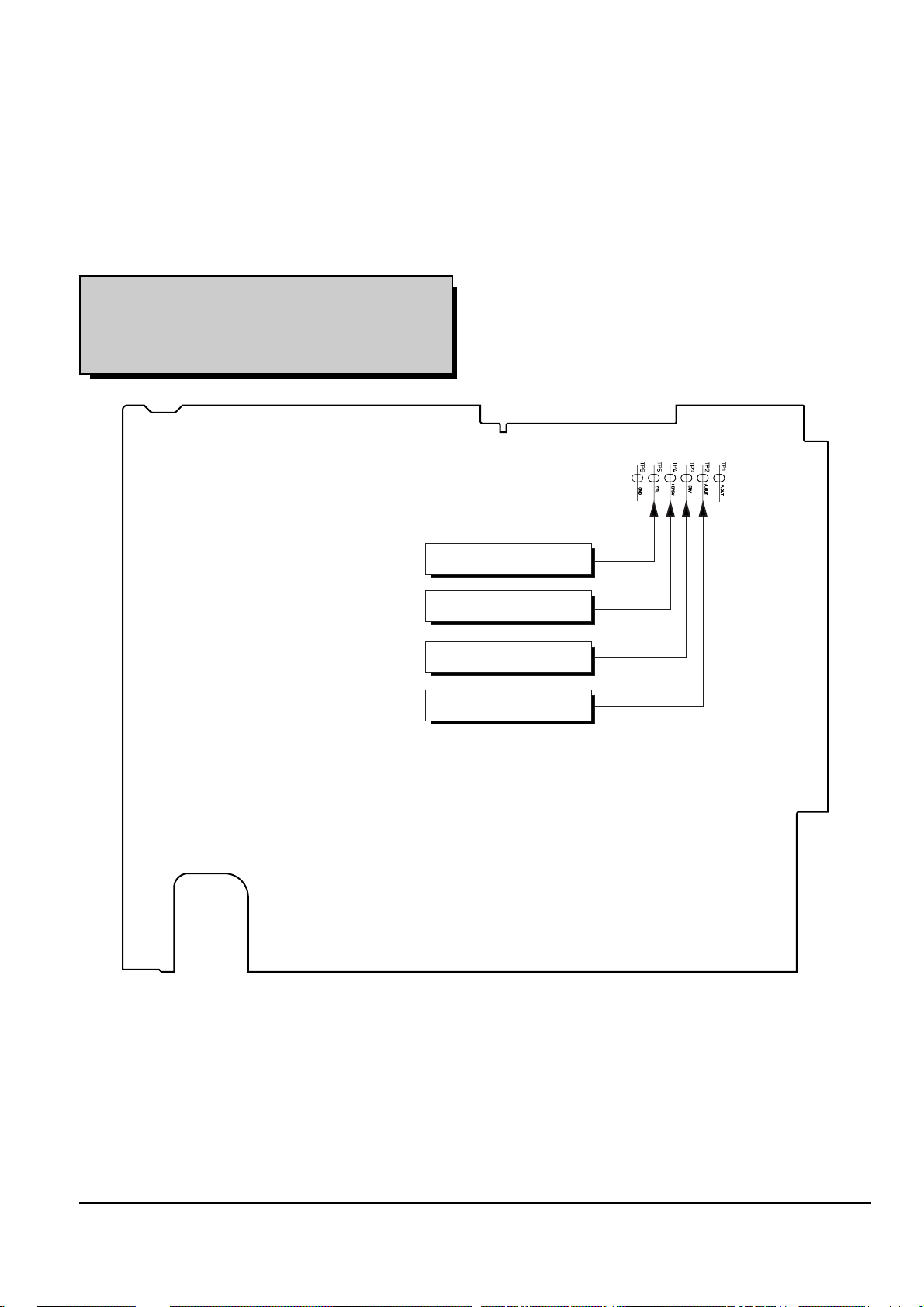
4) Connect the CH-1 probe to “Envelope” the CH-2 probe to “H’D switching pulse” and then trigger to CH-1.
5) Insert the (-) driver into the X-Point adjustment hole and adjust it so that envelope waveform is maximum.
Test point : TP2 (Audio Output)
TP3 (Envelope)
TP4 (H’D S/W -Trigger)
TP5 (Control Pulse)
Fig. 2-13 Location of Test point (Main PCB-Top View)
AUDIO OUTPUT
CONTROL PULSE
HEAD SWITCHING
ENVELOPE
 Loading...