

SAMSUNG SVA20XKSEC Service Manual
VIDEO CASSETTE RECORDER
SV-A20XK/SV-200X
SV-A21XK/SV-201X
SV-A30XK/SV-203X
SV-A40XK/SV-205X
SERVICE
SV-A20XK/SV-A21XK/SV-A30XK
SV-200X/SV-201X/SV-203X
SV-A40XK/SV-205X
Manual
VIDEO CASSETTE RECORDER CONTENTS
PAL
For mechanical disassembly and adjustment, refer to the “Mechanical Manual”
(DX7-R/RC, DX8-R/RC AC68-20316A).
1. Precautions
2. Reference Information
3. Product Specifications and
Comparison Chart
4. Disassembly and Reassembly
5. Alignment and Adjustment
6. Exploded View and Parts List
7. Electrical Parts List
8. Block Diagrams
9. PCB Diagrams
10. Wiring Diagram
11. Schematic Diagrams
© Samsung Electronics Co., Ltd. APR. 1997 AC68-20328A
Samsung Electronics 1-1
1. Precautions
1. Be sure that all of the built-in protective devices are
replaced. Restore any missing protective shields.
2. When reinstalling the chassis and its assemblies, be
sure to restore all pretective devices, including :
control knobs and compartment covers.
3. Make sure that there are no cabinet openings
through which people--particularly children
--might insert fingers and contact dangerous
voltages. Such openings include the spacing
between the picture tube and the cabinet mask,
excessively wide cabinet ventilation slots, and
improperly fitted back covers.
If the measured resistance is less than 1.0 megohm
or greater than 5.2 megohms, an abnormality exists
that must be corrected before the unit is returned
to the customer.
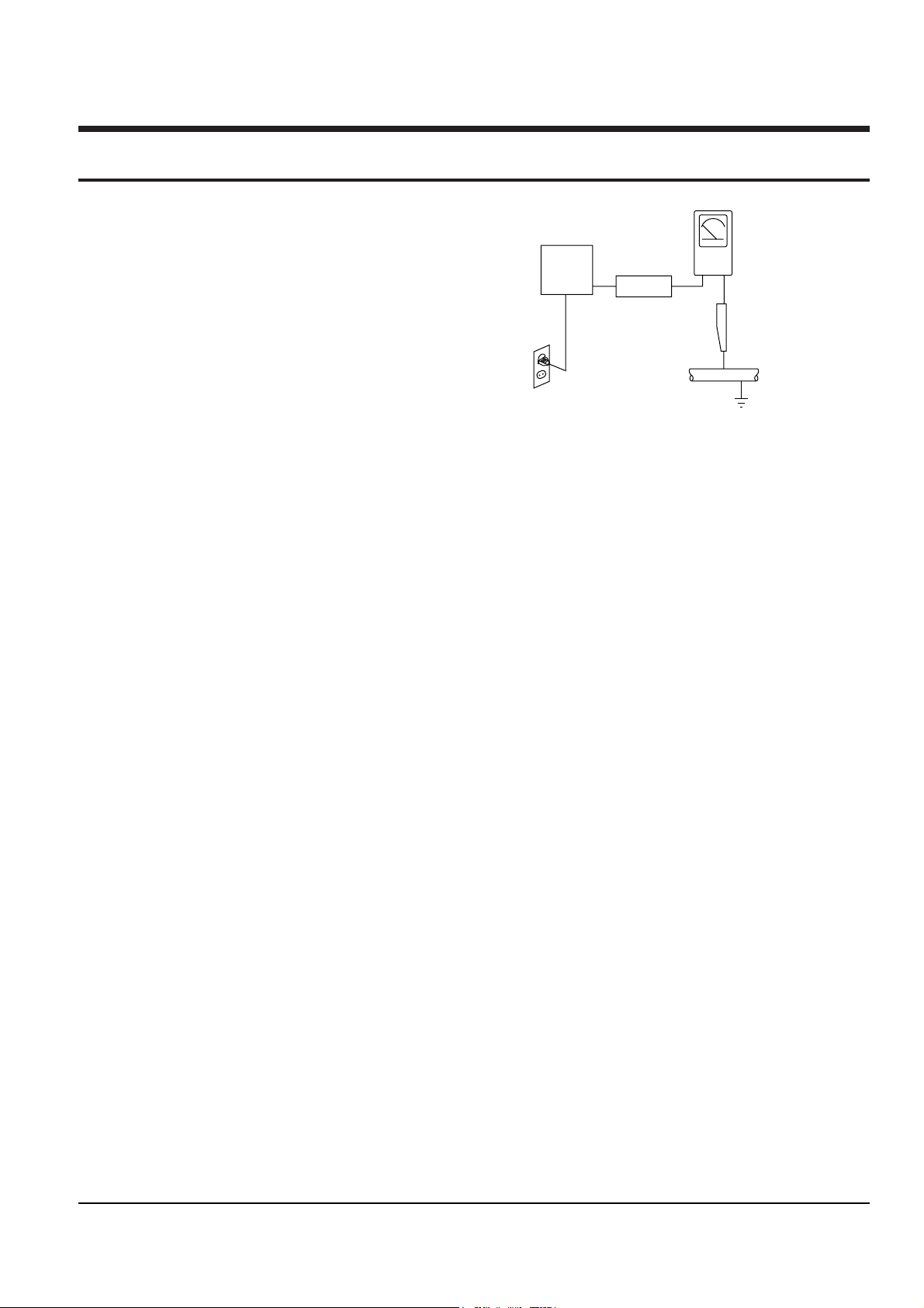
4. Leakage Current Hot Check (See Fig. 1) :
Warning : Do not use an isolation transformer
during this test. Use a leakage current tester or a
metering system that complies with American
National Standards Institute (ANSI C101.1,
Leakage Current for Appliances), and Underwriters
Laboratories (UL Publication UL1410, 59.7).
5. With the unit completely reassembled, plug the AC
line cord directly the power outlet. With the unitÕs
AC switch first in the ON position and then OFF,
measure the current between a known erath
ground (metal water pipe, conduit, etc.) and all
exposed metal parts, including : antennas, handle
brackets, metal cabinets, screwheads and control
shafts. The current measured should not exceed
0.5 milliamp. Reverse the power-plug prongs in the
AC outlet and repeat the test.
6. X-ray Limits :
The picture tube is designed to prohibit X-ray
emissions. To ensure continued X-ray protection,
replace the picture tube only with one that is the
same type as the original.
Fig. 1-1 AC Leakage Test
7. Antenna Cold Check :
With the unitÕs AC plug disconnected from the
AC source, connect an electrical jumper across the
two AC prongs. Connect one lead of the ohmmeter
to an AC prong.
Connect the other lead to the coaxial connector.
8. High Voltage Limit :
High voltage must be measured each time
servicing is done on the B+, horizontal deflection
or high voltage circuits.
Heed the high voltage limits. These include the
X-ray protection Specifications Label, and the
Product Safety and X-ray Warning Note on the
service data schematic.
9. Some semiconductor (Òsolid stateÓ) devices are
easily damaged by static electricity.
Such components are called Electrostatically
Sensitive Devices (ESDs); examples include
integrated circuits and some field-effect transistors.
The following techniques will reduce the
occurrence of component damage caused by static
electricity.
10. Immediately before handling sny semiconductor
components or assemblies, drain the electrostatic
charge from your body by touching a known
earth ground. Alternatively, wear a discharging
Wrist-strap device. (Be sure to remove it prior to
applying power--this is an electric shock
precaution.)
Device
Under
Test
(Reading should
not be above
0.5mA)
Leakage
Currant
Tester
Earth
Ground
Test all
exposed metal
surfaces
Also test with
plug reversed
(using AC adapter
plug as required)
2-Wire Cord

Precautions
1-2 Samsung Electronics
11. High voltage is maintained within specified limits
by close-tolerance, safety-related components and
adjustments. If the high voltage exceeds the
specified limits, check each of the special
components.
12. Design Alteration Warning :
Never alter or add to the mechanical or electrical
design of this unit. Example : Do not add
auxiliary audio or video connectors. Such
alterations might create a safety hazard. Also, any
design changes or additions will void the
manufacturerÕs warranty.
13. Hot Chassis Warning :
Some TV receiver chassis are electrically
connected directly to one conductor of the AC
power cord. If an isolation transformer is not
used, these units may be safely serviced only if
the AC power plug is inserted so that the chassis
is connected to the ground side of the AC source.
To confirm that the AC power plug is inserted
correctly, do the following : Using an AC
voltmeter, measure the voltage between the
chassis and a known earth ground. If the reading
is greater than 1.0V, remove the AC power plug,
reverse its polarity and reinsert. Re-measure the
voltage between the chassis and ground.
14. Some TV chassis are designed to operate with 85
volts AC between chassis and ground, regardless
of the AC plug polarity. These units can be safely
serviced only if an isolation transformer inserted
between the receiver and the power source.
15. Never defeat any of the B+ voltage interlocks.
Do not apply AC power to the unit (or any of its
assemblies) unless all solid-state heat sinks are
correctly installed.
16. Always connect a test instrumentÕs ground lead to
the instrument chassis ground before connecting
the positive lead; always remove the instrumentÕs
ground lead last.
17. Observe the original lead dress, especially near
the following areas : Antenna wiring, sharp
edges, and especially the AC and high voltage
power supplies. Always inspect for pinched, outof-place, or frayed wiring. Do not change the
spacing between components and the printed
circuit board. Check the AC power cord for
damage. Make sure that leads and components
do not touch thermally hot parts.
18. Picture Tube Implosion Warning :
The picture tube in this receiver employs
Òintegral implosionÓ protection. To ensure
continued implosion protection, make sure that
the replacement picture tube is the same as the
original.
19. Do not remove, install or handle the picture tube
without first putting on shatterproof goggles
equipped with side shields. Never handle the
picture tube by its neck. Some Òin-lineÓ picture
tubes are equipped with a permanently attached
deflection yoke; do not try to remove such
Òpermanently attachedÓ yokes from the picture
tube.
20. Product Safety Notice :
Some electrical and mechanical parts have special
safety-related characteristics which might not be
obvious from visual inspection. These safety
features and the protection they give might be
lost if the replacement component differs from the
original--even if the replacement is rated for
higher voltage, wattage, etc.
Components that are critical for safety are
indicated in the circuit diagram by shading,
( or ).
Use replacement components that have the same
ratings, especially for flame resistance and
dielectric strength specifications. A replacement
part that does not have the same safety
characteristics as the original might create shock,
fire or other hazards.
Samsung Electronics 2-1
2. Reference Information
2-1 Servicing Jigs and Special Tools
1. For this VCR chassis, the program switch and the
sensors (start/end/reel) are located on the main
PCB, not on the deck assÕy.
2. As long as the deck assÕy is connected to the main
PCB, all repairs are possible.
Important : In order to repair the main PCB
without the deck assÕy connected, the X-5 chassis
jig should be used.
3. To emulate the function of the sensors, connect a
jumper or solder land (two point) at service
option(W750) on the function-timer PCB.
4. The X-5 chassis jig can be used for the following :
1) When repairing or confirming the operation of the
deck assÕy.
2) When replacing or repairing the components
located under the deck assÕy.
3) When repairing the function PCB.
5. The X-5 chassis jig can not be used for the
following :
1) Repairing defects in the video section.
2) Repairing defects in the audio section.
3) If the defect is related to tape speed.
Note :
1) Repair may not be possible if there is external
noise between the deck assÕy and main PCB.
2) If tape control signal is not connected to the jig,
the VCR must be operated in SP mode.
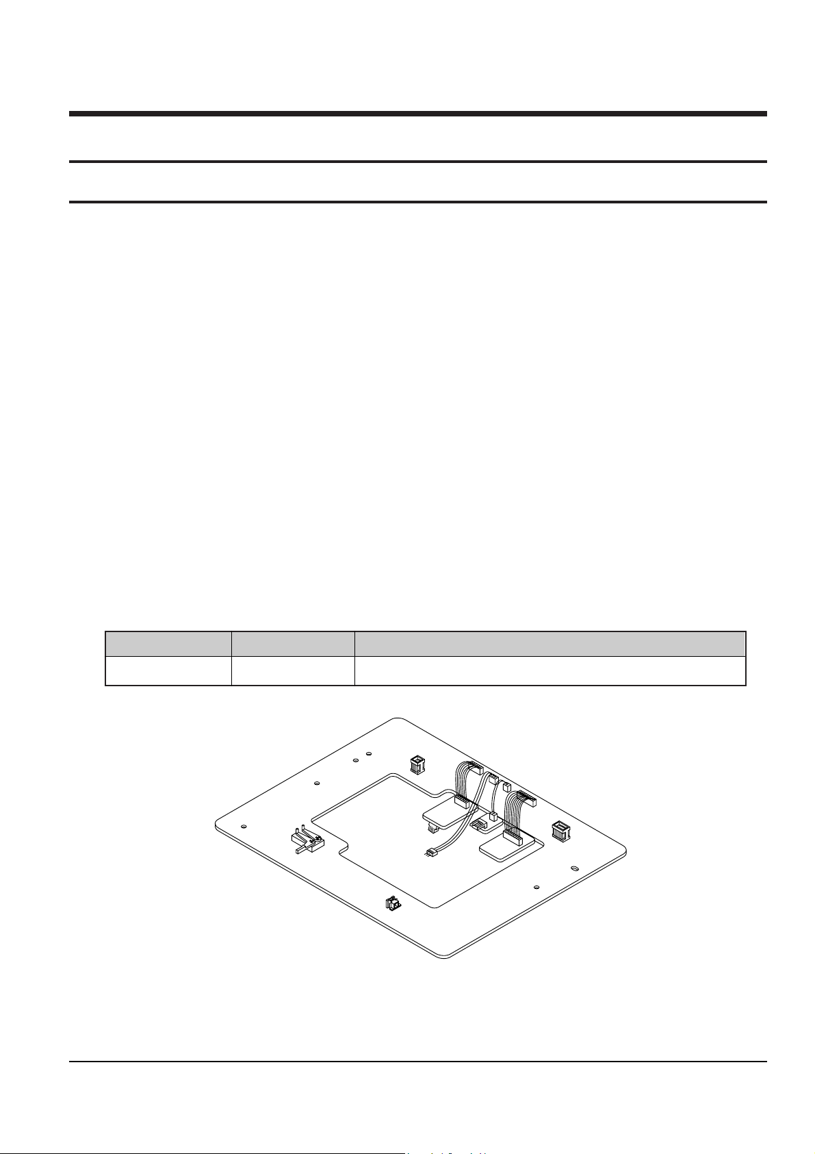
2-1-1 Servicing guide
X-5 Chassis Jig
Jig Item
68140-500-013
Part No.
Connects the deck ass’y to the main PCB connecting cable.
Use
2-1-2 Servicing Jig
Reference Information
2-2 Samsung Electronics
2-1-4 How to Connect X-5 chassis jig
4. Insert wafers of drum motor, capstan motor and
loading motor on X-5 chassis jig into each of the
connectors of deck assÕy, and then secure with
three screws.
5. Solder the 3 leads of the jig cable to ÒCN605Ó
on the main PCB.
6. Apply power to the function PCB.
7. Insert a test tape into the housing assÕy.
8. Simultaneously touch the start and end sensor
LEDs on the PCB, so that the tape loads
automatically. After the tape is loaded, all of the
function buttons on the function PCB can be
used.
9. If the test tape is ejected while the jig is in use,
attempt to re-load the tape by simultaneously
touching the start and end sensor LEDs. If the tape
still does not load, reset the function PCB by
pressing SW715.
Note : After completing repairs, SW715 on the function PCB in order to reset.
1. Unplug the power cord from AC outlet.
2. Remove the deck assÕy from main PCB (See Page
4-5 of service manual).
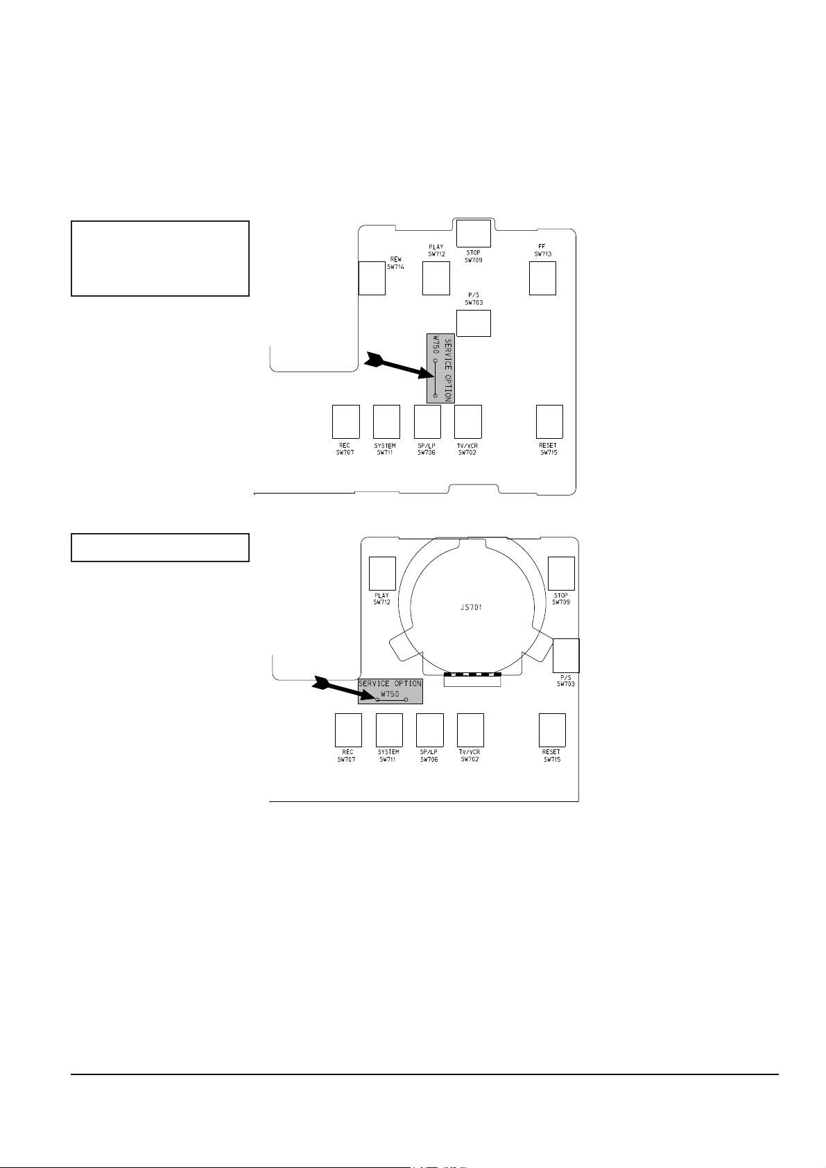
3. To emulate the function of the sensors, place a
jumper or solder land (two point) at service
option(W750) on the function-timer PCB.
(see diagram below).
Function-Timer (Component side)
Function-Timer (Component side)
SV-A20XK/SV-200X
SV-A21XK/SV-201X
SV-A30XK/SV-203X
SV-A40XK/SV-205X
Reference Information
Samsung Electronics 2-3
CONNECTS TO THE ASS'Y MAIN CN604.
CONNECTS TO THE ASS'Y MAIN CN605.
CONNECTS TO THE
ASS'Y MAIN CN603.
CONNECTS TO THE ASS'Y MAIN CN601.
CONNECTS TO THE DRUM MOTOR
CONNECTOR OF ASS'Y FULL DECK.
CONNECTS TO THE CAPSTAN MOTOR
CONNECTOR OF ASS'Y FULL DECK.
CONNECTS TO THE LOADING MOTOR CONNECTOR OF ASS'Y FULL DECK.
ASS'Y FULL DECK
ASS'Y MAIN
1 SCREW (1-3X10)
2 SCREWS (2-3X10)
CN604
CN603
CN605
CN601
How to Connect X-5 chassis jig
Reference Information
2-4 Samsung Electronics
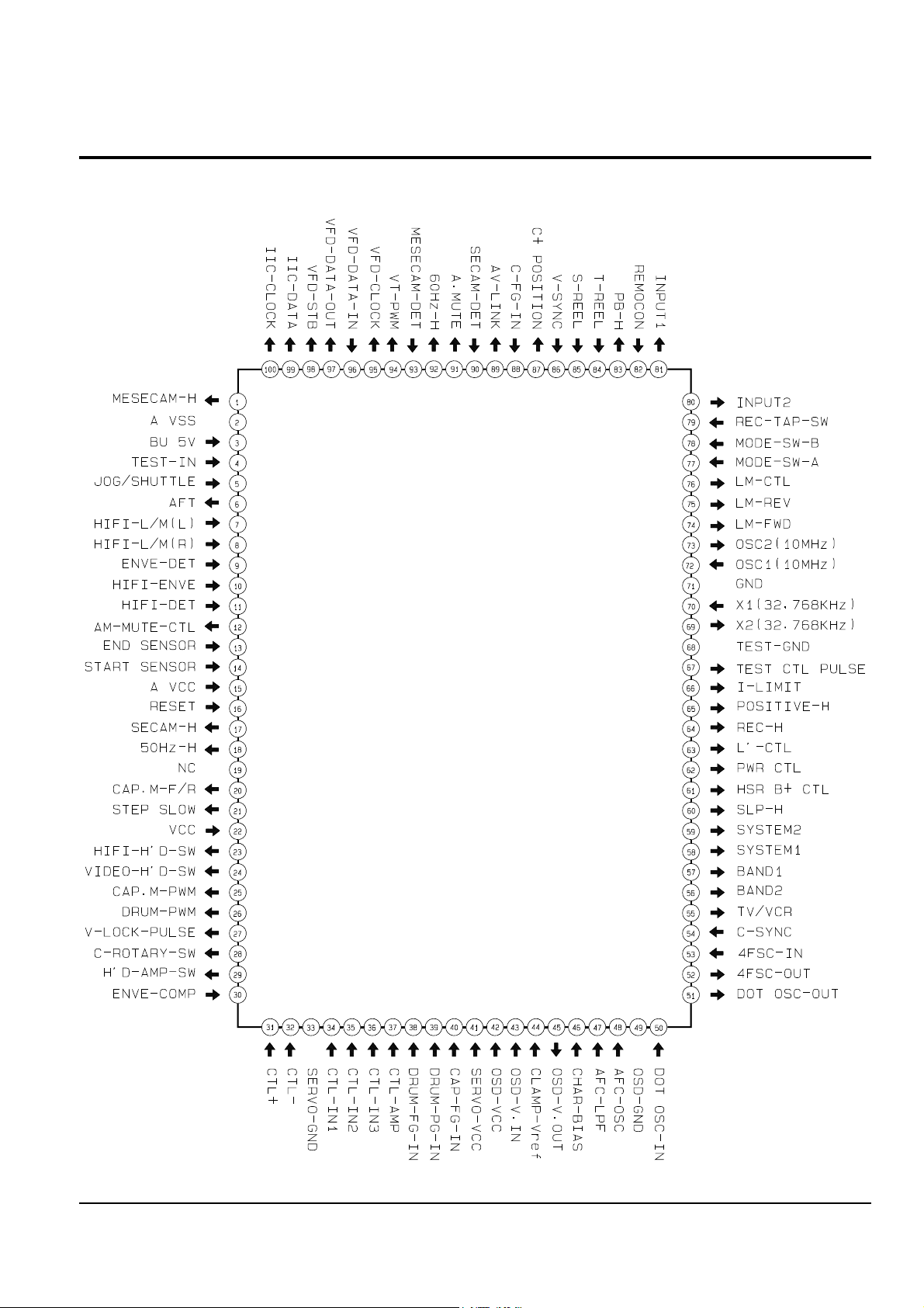
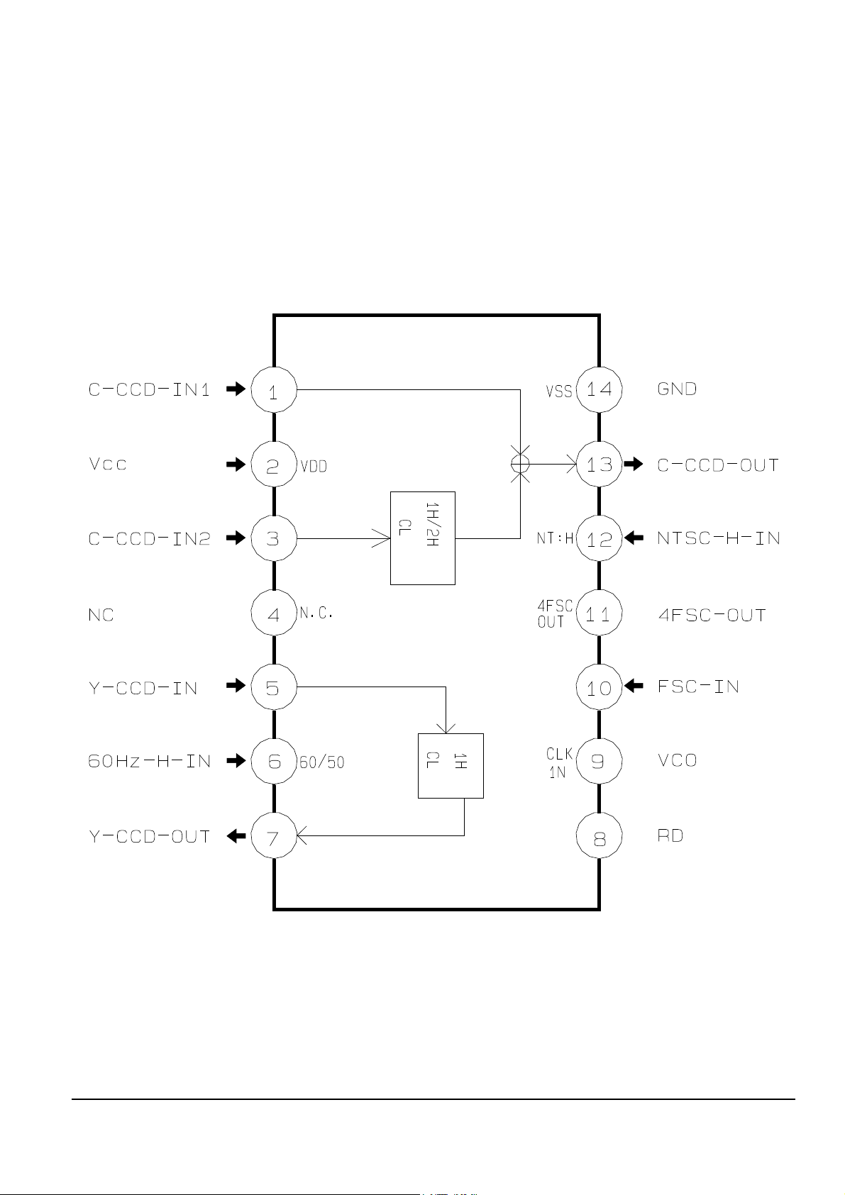
2-2 IC BLOCK
2-2-1 IC601 (HD6473977)
Reference Information
Samsung Electronics 2-5
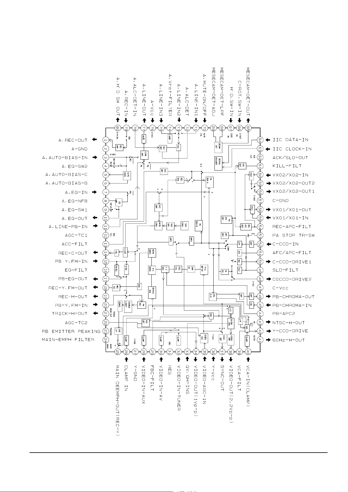
2-2-2 IC301 (SS11501M)
Reference Information
2-6 Samsung Electronics
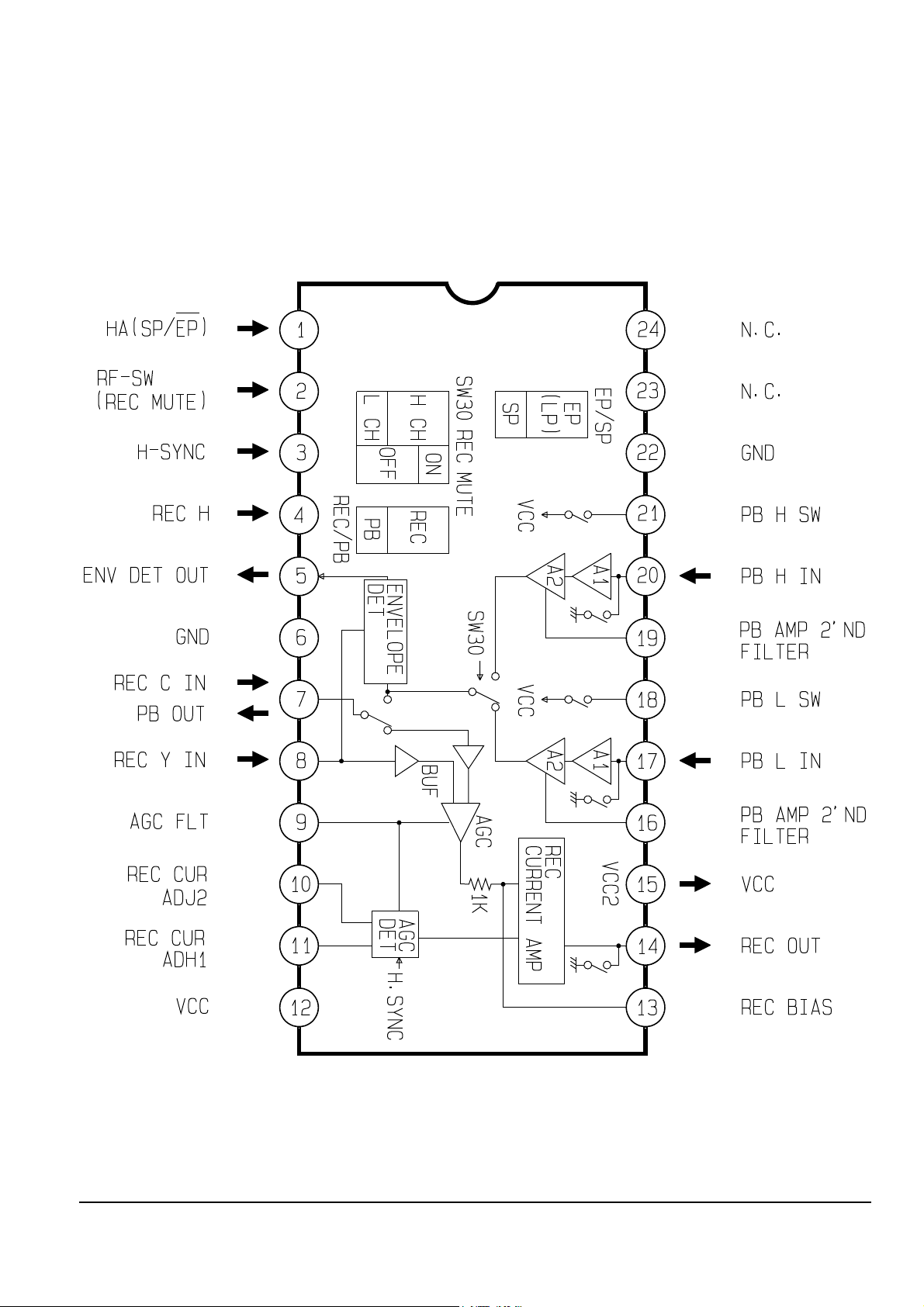
2-2-3 IC302 (LA7411)
Reference Information
Samsung Electronics 2-7
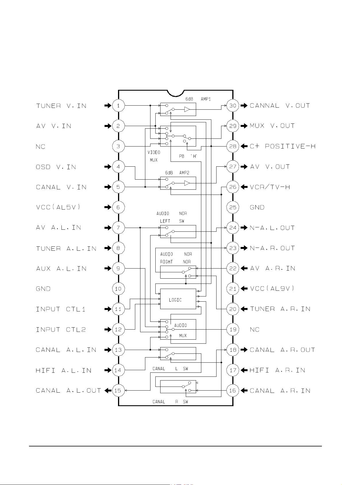
2-2-4 IC303 (SS23478M)
Reference Information
2-8 Samsung Electronics
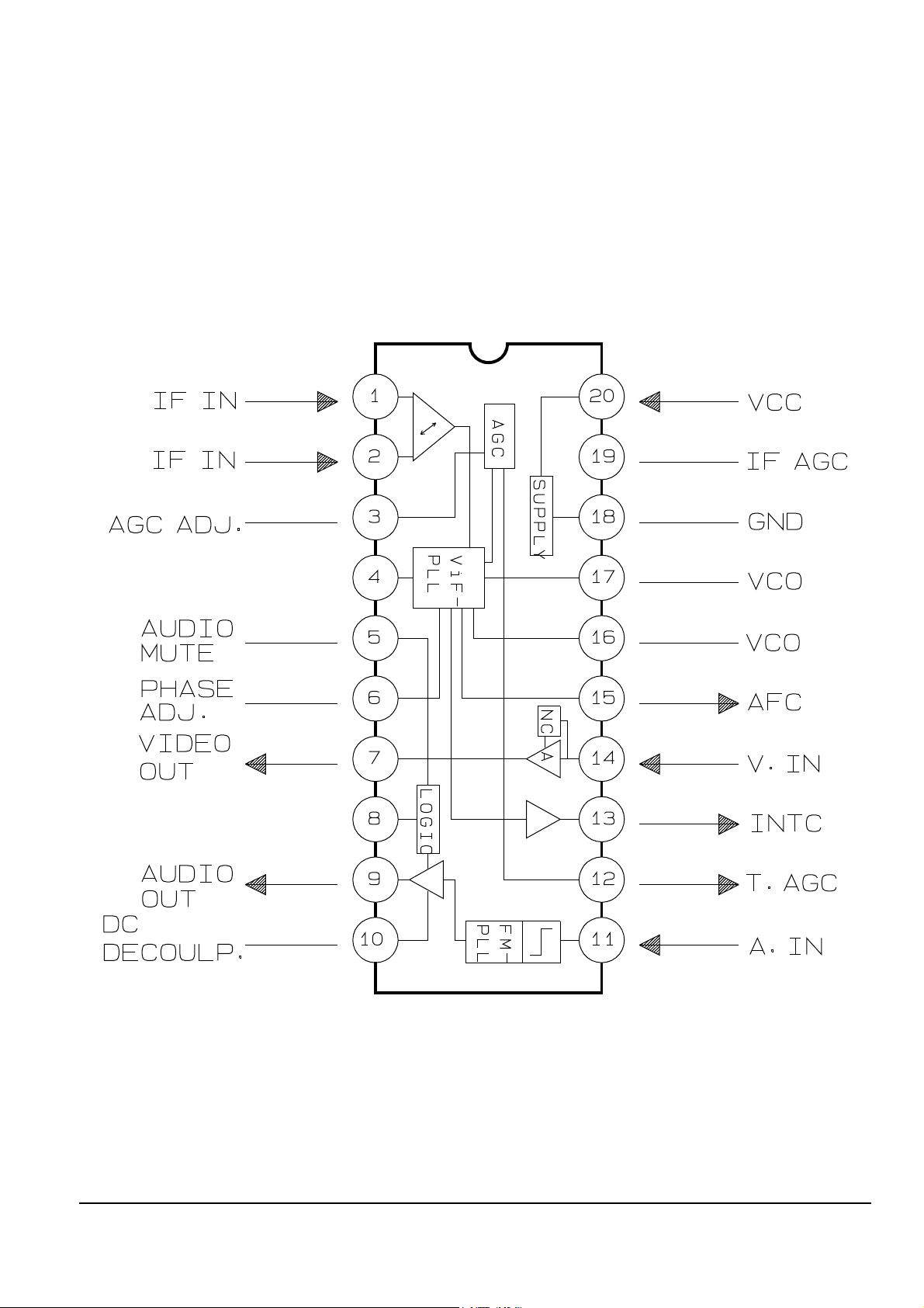
2-2-5 IC401 (TDA9800)
Reference Information
Samsung Electronics 2-9
2-2-6 IC801 (KA8119)

Reference Information
2-10 Samsung Electronics
MEMO
Samsung Electronics 3-1
3. Product Specifications and Comparison Chart
3-1 Product Specifications
Operation Description
Format VHS PAL/MESECAM standard
Heads Video : 2 rotary heads
Audio/Control : 1 stationary head
Erase : 1 full track erase head
Receiving channel VHF-I, VHF-III, UHF, Hyperband
Television system STANDARD B/G
Luminance FM azimuth recording
Colour system PAL/MESECAM : Down converted subcarrier phase shifted direct recording
NTSC PB on PAL TV
Tape speed SP : 23.39 mm/sec
Recording/playback time SP : 3 hours (E-180 Tape)
F.F/REW time About 100-190 sec in REW/F.F with E-180
VIDEO
Input 0.5 to 2.0 Vp-p : 75 ohm unbalanced
Output 1.0 ± 0.2 Vp-p : 75 ohm unbalanced
Signal-to-noise ratio Better than 43 dB (SP)
Horizontal resolution More than 240 lines (SP)
Audio
Input -8 dBm, 47 Kohm unbalanced
Output -8 ± 3 dBm, 1 Kohm unbalanced
Wow and flutter (WTD) 0.4% max (SP)
Signal-to-noise ratio 42 dB min (IHF A filter)
Frequency response 100Hz-8KHz
Power requirement 230V (AC 50/60 Hz)
Power consumption Approx. 18 watts
Operation temperature 41°F-104°F (5°C-40°C)
Operation humidity 10%-75%
Weight 4.4 Kg (net)
Dimensions (W x H x D) 380 x 90.5 x 310 mm
Design and specifications are subject to change without notice.
Product Specifications
3-2 Samsung Electronics
3-2 Comparison Chart
SV-A20XK/EDI (SV-200X) X X X X X X X X 1 SCART X X
SV-A20XK/NSI (SV-200X) X X X X X X X X 1 SCART X X
SV-A20XK/AMF (SV-200X) X X X X X X X X 1 SCART X X
SV-A20XK/SEI (SV-200X) X X X X X X X X 1 SCART X X
SV-A20XK/SEC (SV-200X) X X X X X X X X 1 SCART X X
SV-A21XK/SEI (SV-201X) X X X X X X X X 2 SCART CANAL+ O
SV-A21XK/SEC (SV-201X) X X X X X X X X 2 SCART CANAL+ O
SV-A30XK/SEG (SV-203X) X X O X O O O X 1 SCART X X
SV-A40XK/EDI (SV-205X) O O X O O O O O 2 SCART CANAL+ O
SV-A40XK/NSI (SV-205X) O O X O O O O O 2 SCART CANAL+ O
SV-A40XK/AMF (SV-205X) O O X O O O O O 2 SCART CANAL+ O
SV-A40XK/SEI (SV-205X) O O X O O O O O 2 SCART CANAL+ O
SV-A40XK/SEC (SV-205X) O O X O O O O O 2 SCART CANAL+ O
SV-A40XK/SEG (SV-205X) O O O X O O O O O P/MIERE O
FUNCTION
MODEL
SHUTTLE
AUDIO
DUBBING
VPS
PDC
SHOW
VIEW
ATS
AUTO
CLOCK
FRONT
A/V
REAR
JACK
CANAL+
P/MIERE
VCR/
TV
REMARK
Samsung Electronics 4-1
4. Disassembly and Reassembly
4-1 Cabinet Assembly
Note : Disassemble in the order shown.
Reassemble in reverse order.
4-1-1 Cabinet Top removal
REMOVE 5 SCREWS
1. Remove 5 screws and slide the top cabinet to the rear to remove.
Fig. 4-1 Cabinet Top removal
Disassembly and Reassembly
4-2 Samsung Electronics
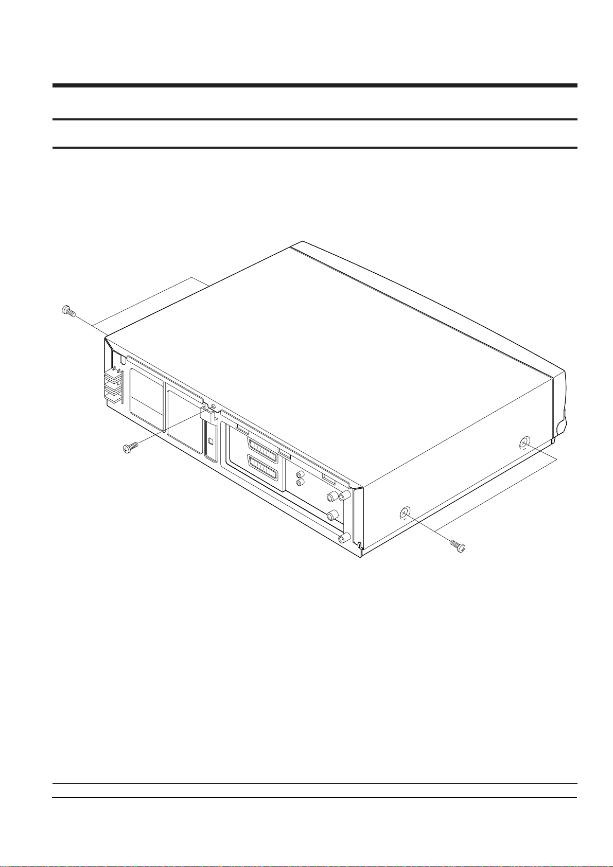
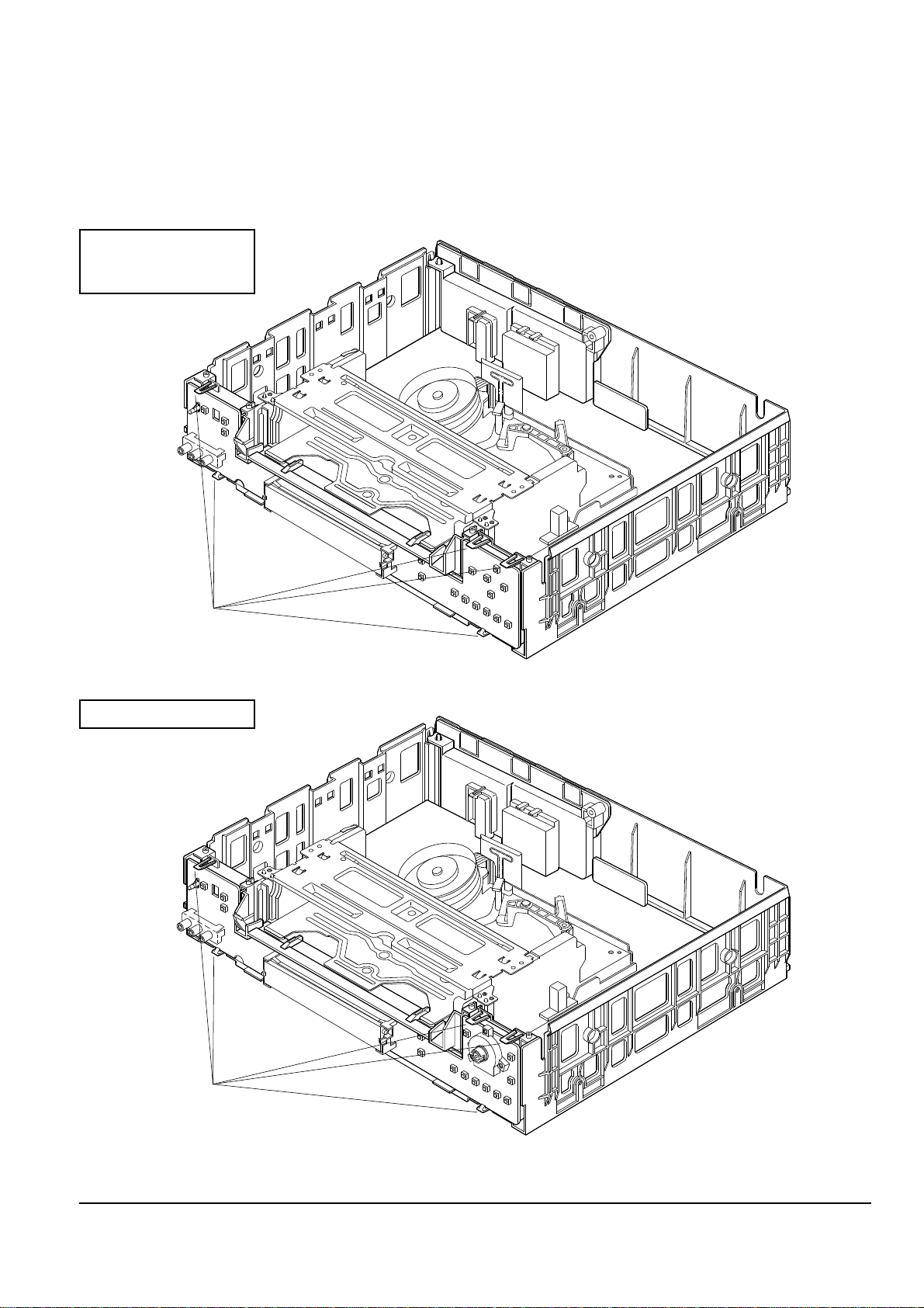
4-1-2 Bottom cover removal
1. Remove 2 screws.
2. Lift up the bottom cover toward arrow ÒAÓ.
Fig. 4-2 Bottom Cover removal
"A"
REMOVE 2 SCREWS
(BH;1-3X12 YELLOW)
1
2
Lift up the bottom cover
in the direction of arrow "A".
REMOVE 2 SCREWS
(BH;1-3X12 YELLOW)
1
"A"
2
Lift up the bottom cover
in the direction of arrow "A".
SV-A20XK/SV-200X
SV-A21XK/SV-201X
SV-A30XK/SV-203X
SV-A40XK/SV-205X
Disassembly and Reassembly
Samsung Electronics 4-3
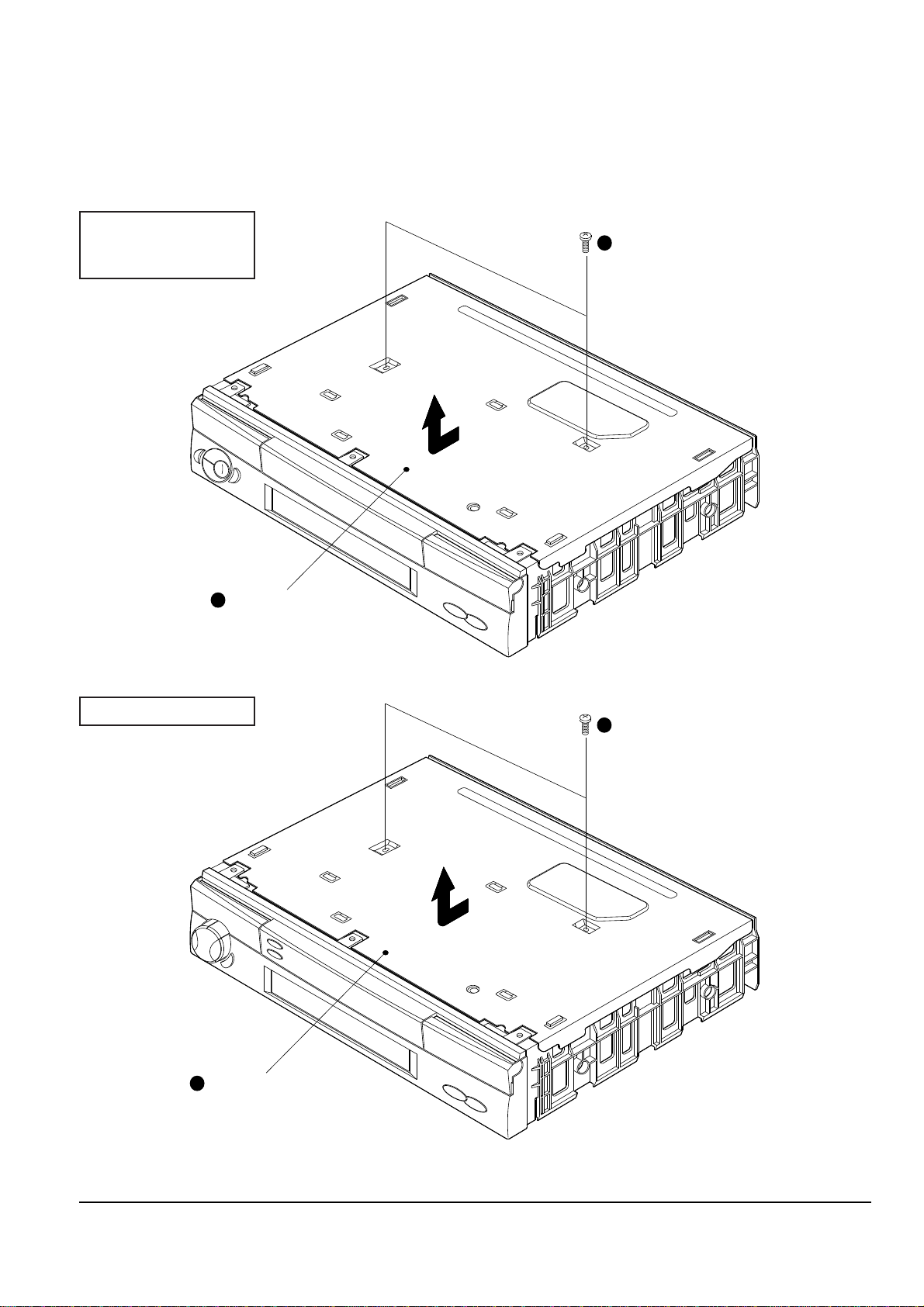
4-1-3 Ass’y Front Panel removal
(Bottom view)
RELEASE 4 HOOKS
REMOVE
KNOB-SHUTTLE
12
RELEASE 3 HOOKS
3
1. Remove the knob-shuttle.
2. Release 4 hooks on the top side and 3 hooks on the bottom side and then, pull the assÕy front panel to remove.
(Top view)
Fig. 4-3 Ass’y Front Panel removal
Disassembly and Reassembly
4-4 Samsung Electronics
4-1-4 Ass’y Function-Timer removal
1. Release 5 hooks and remove the assÕy function-timder.
Note : Take extreme care not to damage the PCB when removing it.
Fig. 4-4 Ass’y Function-Timer removal
RELEASE 5 HOOKS
RELEASE 5 HOOKS
SV-A20XK/SV-200X
SV-A21XK/SV-201X
SV-A30XK/SV-203X
SV-A40XK/SV-205X
Disassembly and Reassembly
Samsung Electronics 4-5
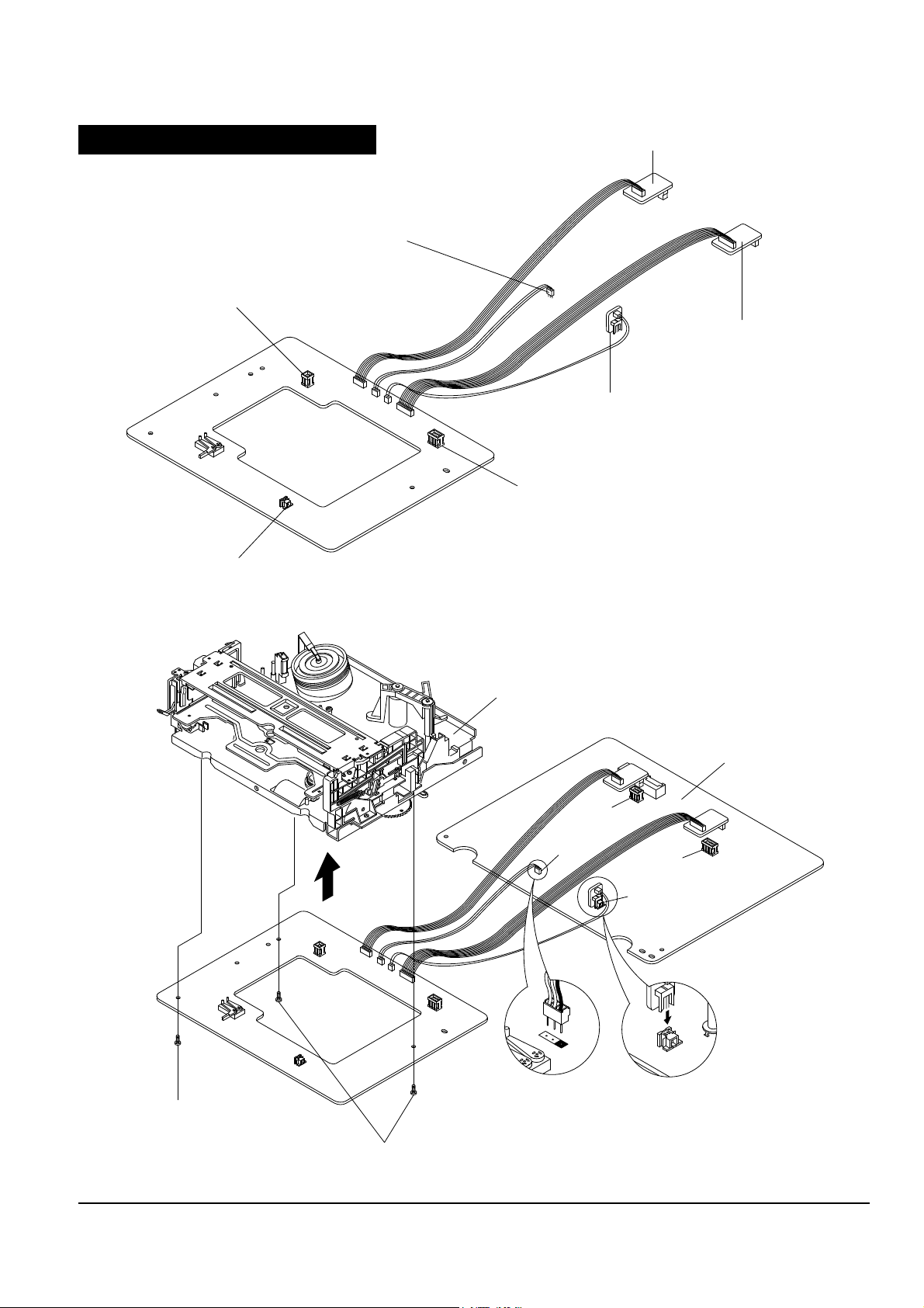
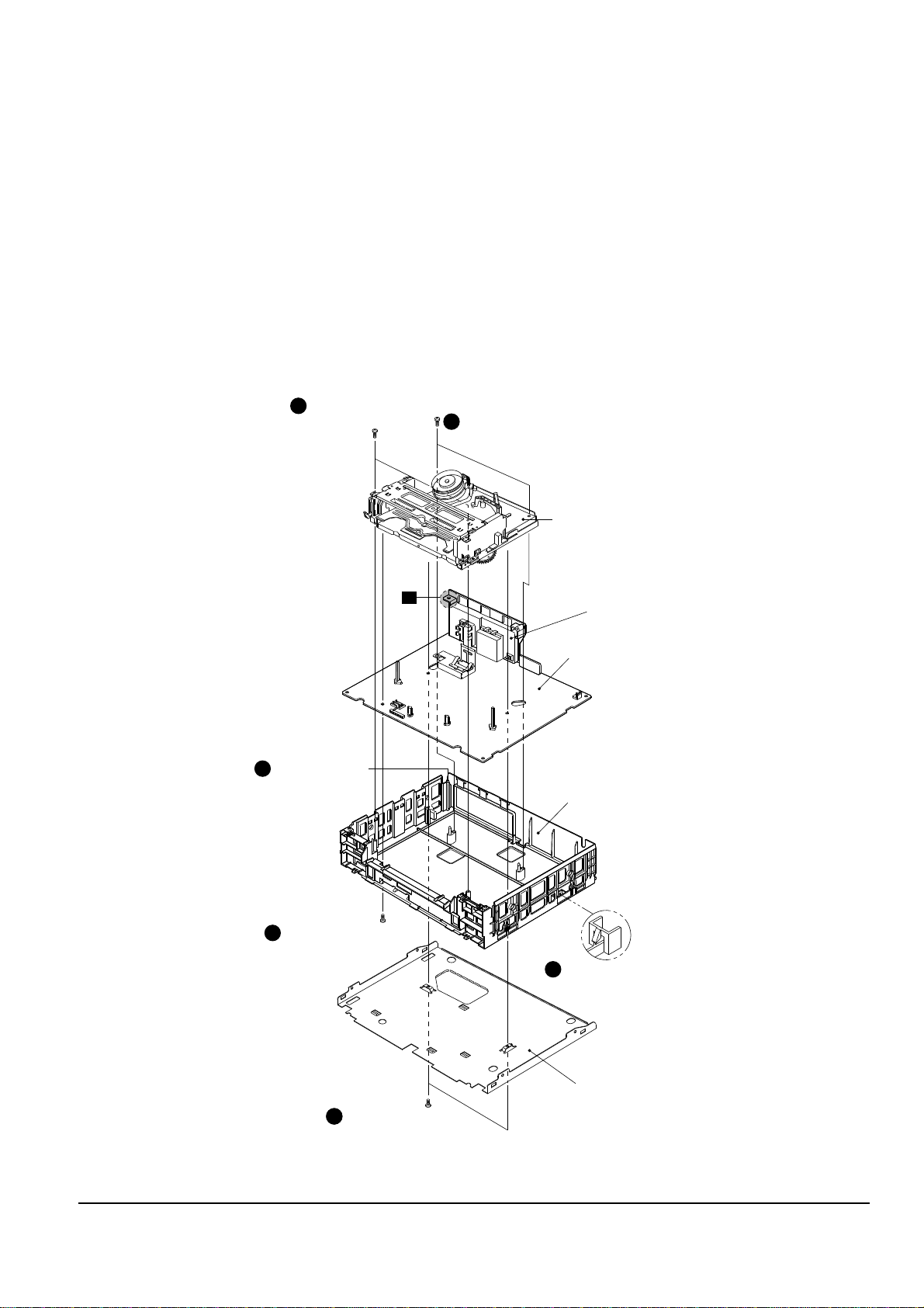
4-1-5 Chassis removal
REMOVE 2 SCREWS
(BH;2-3X12 YELLOW)
1
REMOVE 2 SCREWS
(BH;2-3X12 YELLOW)
2
REMOVE 2 SCREWS
(BH;2-3X12 YELLOW)
1
REMOVE 2 SCREWS
(BH;2-3X12 YELLOW)
4
REMOVE 2 SCREWS
(BH;2-3X12 YELLOW)
3
RELEASE 1 TAB
5
RELEASE 1 HOOK
6
A
CONNECTOR BOARD ASS'Y
ASS'Y MAIN
ASS'Y FULL DECK
BOTTOM COVER
FRAME
1. Remove 2 screws holding the bottom cover.
2. Remove 2 screws holding the frame.
3. Remove 2 screws holding the housing assÕy.
4. Remove 2 screws holding the assÕy full deck.
5. Lift the assÕy full deck up.
6. Release 1 tab holding the connector board assÕy.
7. Release 1 hook holding the assÕy main.
8. Lift the assÕy main up to remove.
Note : 1. When removing chassis, take extreme care not to damage the main PCB front.
2. When reinstalling the deck on the main PCB, take extreme care not to damage the sensor.
Fig. 4-5 Chassis Removal
Disassembly and Reassembly
4-6 Samsung Electronics
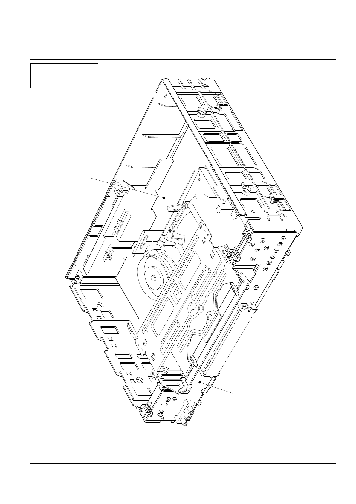
4-2 Circuit Board Locations
ASS'Y MAIN BOARD
ASS'Y FUNCTION-TIMER BOARD
Fig. 4-6 Circuit Board Locations
SV-A20XK/SV-200X
SV-A21XK/SV-201X
SV-A30XK/SV-203X
Disassembly and Reassembly
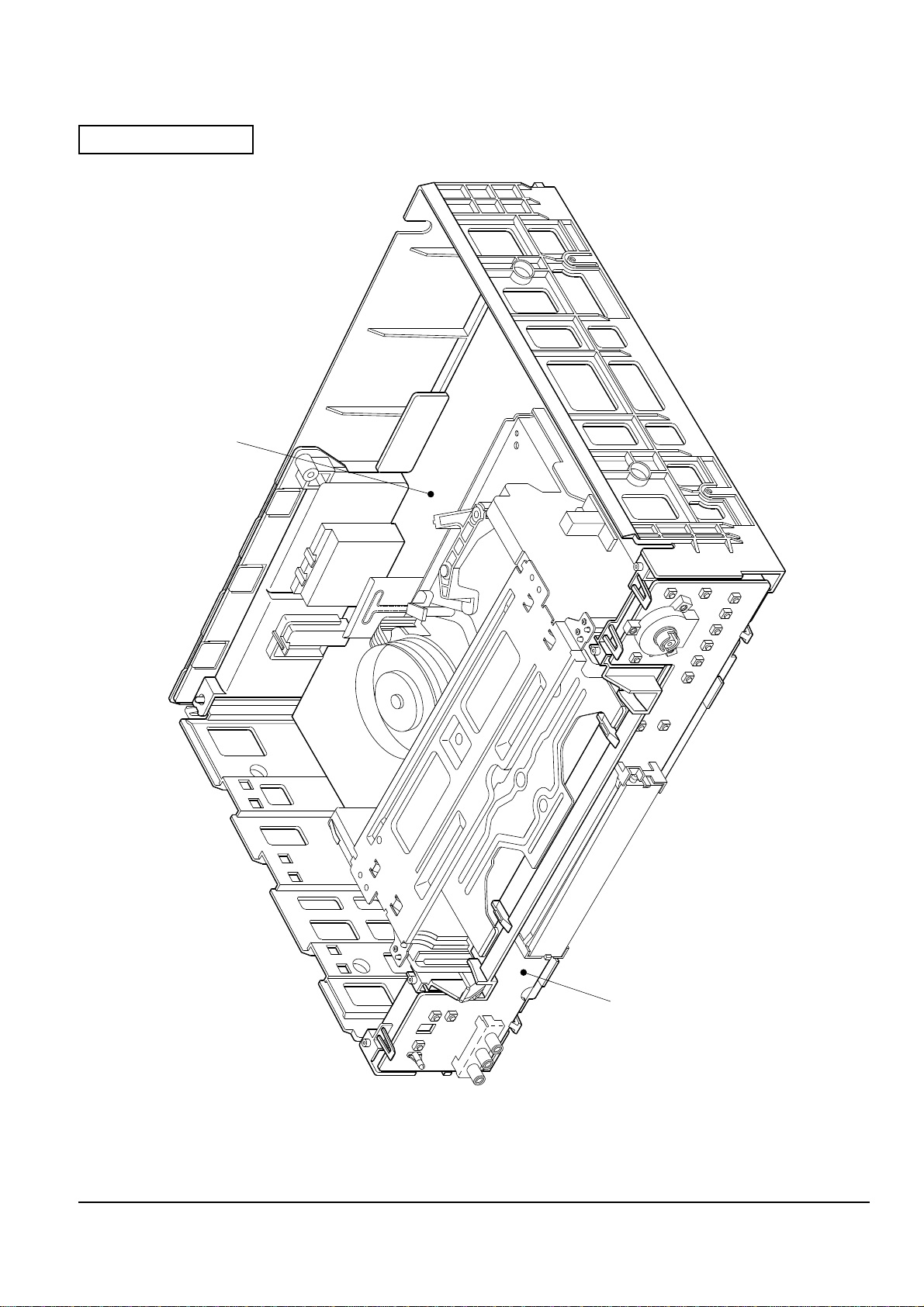
Samsung Electronics 4-7
ASS'Y MAIN BOARD
ASS'Y FUNCTION-TIMER BOARD
Fig. 4-6 Circuit Board Locations
SV-A40XK/SV-205X

Disassembly and Reassembly
4-8 Samsung Electronics
MEMO
Samsung Electronics 5-1
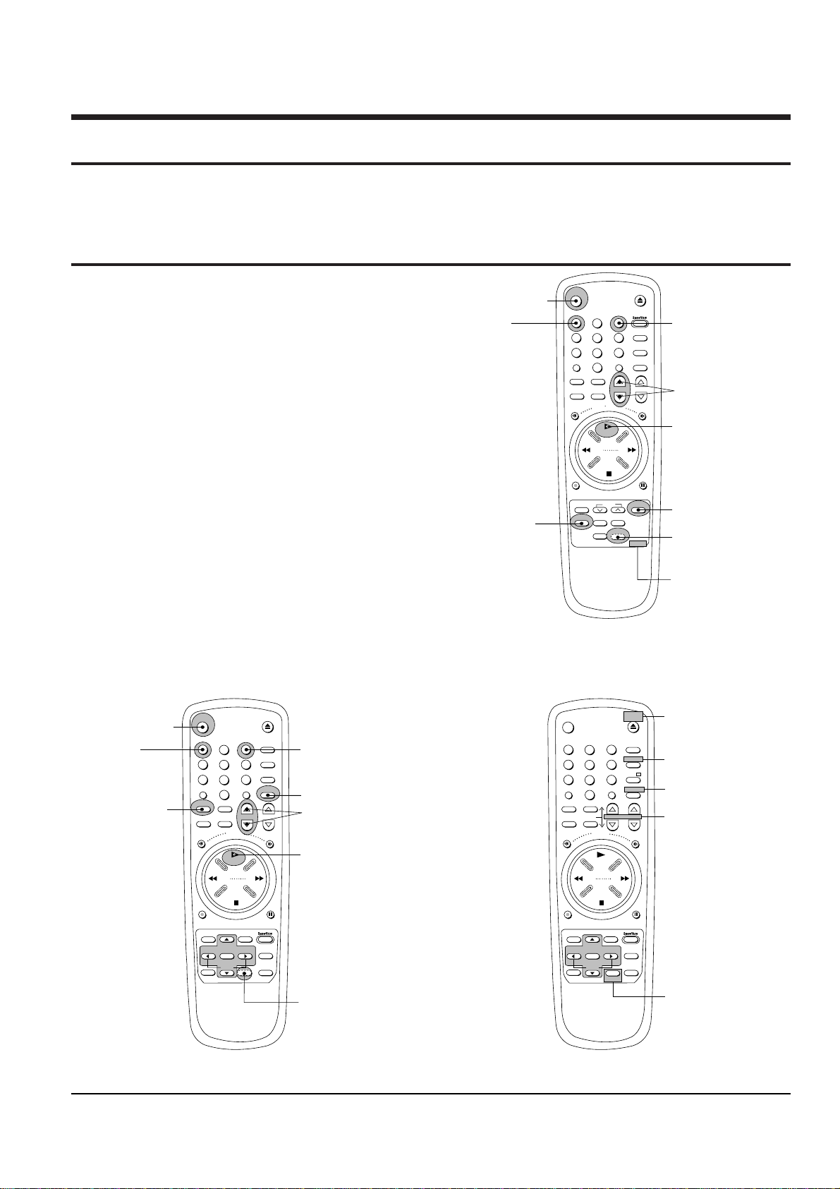
5. Alignment and Adjustment
Note : After replacing the assÕy full deck, the assÕy main, the cylinder assÕy and the micom(IC601), the remote
control assÕy can be used to adjust the ÒX-point (tracking center) adjustmentÓ and ÒHead S/W pointÓ
adjustment.
5-1 Reference
5-1-1 The type of remote control ass’y
1. Remote control assÕy (AC93-10039Y/69099-633-252)
is specified as a service jig in the service manual of
X-5/X-6(DX5-R/DX5-RC/DX6-R/DX6-RC) chassis.
(See Fig. 5-1)
2. Normal remote control assÕy for X-7/X-8
(DX7-R/DX7-RC/DX8-R/DX8-RC) chassis.
(See Fig. 5-2)
5-1-2 How to identify between normal
remote control ass’y and multi
remote control ass’y for X-7/X-8
chassis (See Fig. 5-2)
1. The color of some buttons related to TV function are
gold.
2. Audio button is added instead of the test button
hidden behind of inlay.
3. The positions of some buttons are different.
EJECT
2
45 6
789
0
CLK/COUNT
REW
F.F
STOP
CLR/RST DISPLAY
Q-PRO
MENU
S
H
I
F
T
S
H
U
T
T
L
E
DAILY WEEKLY
REC
P/S
PRESET BAND
SEARCH MEMORY
OUTPUT
INDEX SLOW INPUT
INPUT BUTTON
SP/LP BUTTON
SP LP A.DUB VPS
FINE CH
TRK
(TRACKING, FINE)
BUTTON
POWER BUTTON
POWER
PLAY BUTTON
PLAY
TEST BUTTON IS
HIDDEN BEHIND
OF INLAY.
3
HEAD S/W ADJ.
("INPUT" OR "TEST"
AND "3" BUTTON)
1
TRACKING
CENTER ADJ.
("INPUT" OR "TEST"
AND "1" BUTTON)
633-252
REMOTE CONTROL
ASS'Y PART NO.
Fig. 5-1 Remote Control Ass’y Jig for X-5/X-6 Chassis
(AC93-10039Y/69099-633-252)
EJECT
2
45 6
789
0
CLK/COUNT
REW
F.F
STOP
AUDIO
DISPLAY
REC
P/S
INDEX A.TRK
INPUT BUTTON
FINE PROG
TRK
(TRACKING, FINE)
BUTTON
POWER BUTTON
POWER
PLAY BUTTON
PLAY
TEST BUTTON IS
HIDDEN BEHIND
OF INLAY.
3
HEAD S/W ADJ.
("INPUT" OR "TEST"
AND "3" BUTTON)
1
TRACKING
CENTER ADJ.
("INPUT" OR "TEST"
AND "1" BUTTON)
SYSTEM
CLR/RST
S
H
U
T
T
L
E
SPEED BUTTON
SPEED AFT
INPUT
TV/VCR
PICTURE
A.DUB
2
45 6
789
0
CLK/COUNT
REW
F.F
STOP
DISP./
REC
P/S
INDEX
VCR
POWER
PLAY
3
1
VCR
CLR/RST
S
H
U
T
T
L
E
SPEED
TV/VCR
PICTURE
A.DUB
NORMAL REMOTE CONTROL ASS'Y
(CAN ADJUST)
MULTI REMOTE CONTROL ASS'Y
(CAN NOT ADJUST)
-/--
FINE
AUDIO
ADD BUTTON(AUDIO)
GOLD COLOR
TV
GOLD COLOR
TV
POWER
INPUT
GOLD COLOR
VOLUME PROG
GOLD COLOR
MENU
Q-PRO
SLOW
SOFTEN OK SHARPEN
MENU
Q-PRO
SLOW
SOFTEN OK SHARPEN
Fig. 5-2 Remote Control Ass’y for X-7/X-8 Chassis
 Loading...