

Page 1
Samsung Electronics 2-1
2. Reference Information
2-1 Important Service Guide
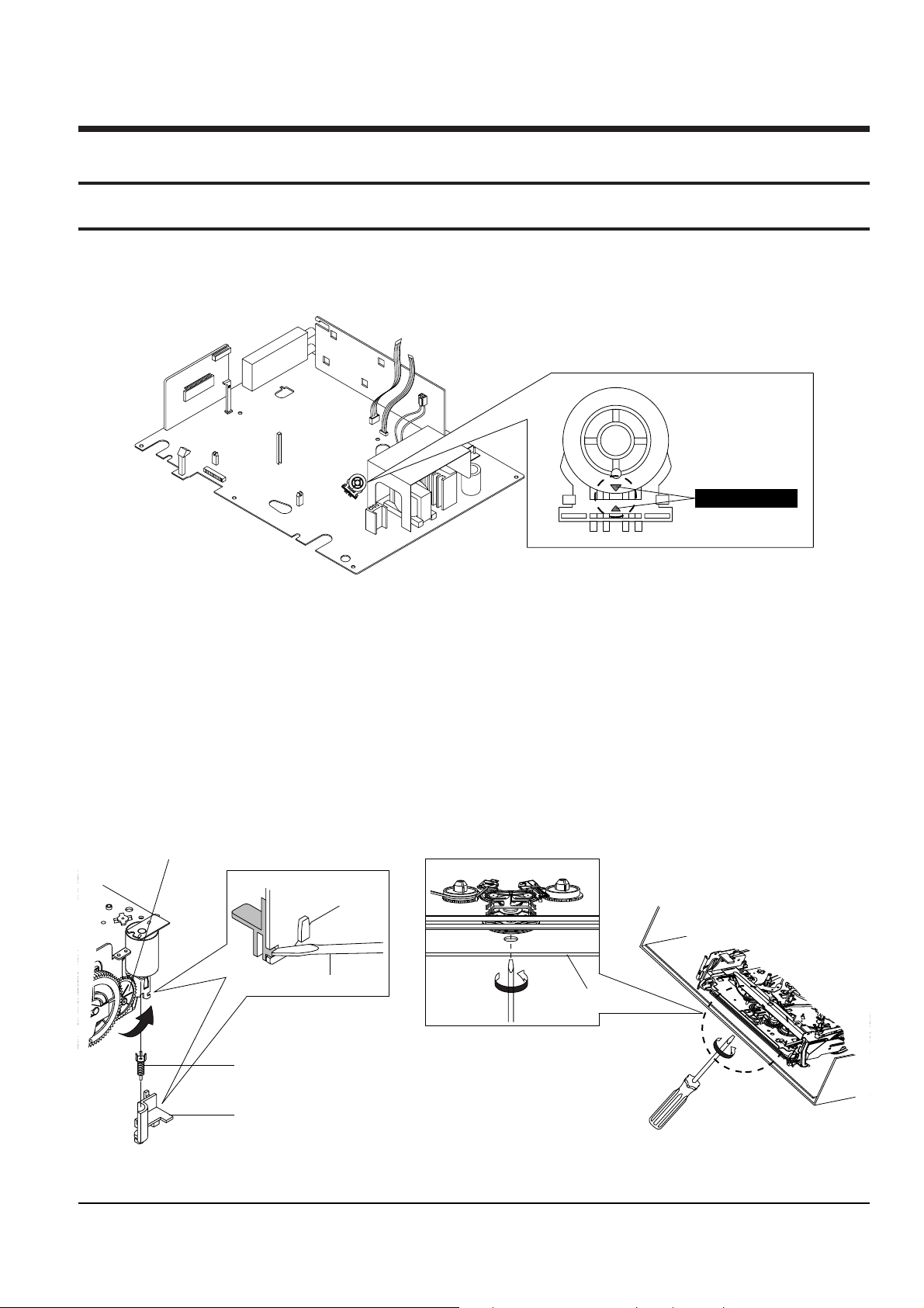
2-1-1 Mode switch (Program Switch) assembly point
1) When installing the assÕy full deck on the Main PCB, be sure to align the assembly point of mode switch.
2-1-2 How to eject the cassette tape
(If the unit does not operate on condition that tape is inserted into housing ass’y)
1) Remove the Holder Worm Œ and the gear worm ´. (See Fig. 2-2)
2) Turn the Gear Worm Wheel ˇ counterclockwise in the direction of arrow with screw driver. (See Fig. 2-2)
3) When Slider S, T are approached in the position of unloading, rotate holder Clutch counterclockwise after
inserting screw driver in the hole of frameÕs bottom in order to wind the unwounded tape. (Refer to Fig. 2-3)
(If you rotate Gear Worm Wheel continuously when tape is in state of unwinding, you may cause a tape conta
mination by grease and tape damage. Be sure to wind the unwounded tape in the state of set horizontally.)
4) Rotate Gear Worm Wheel ˇ counterclockwise using screw driver again up to the state of eject mode and then
pick out the tape. (Refer to Fig. 2-2)
Fig. 2-2 Fig. 2-3
ΠHOLDER WORM
´ GEAR WORM
SCREW DRIVER
ˇ GEAR WORM WHEEL
FRAME
ASSEMBLY POINT
Fig. 2-1
Page 2
Reference Information
2-2 Samsung Electronics
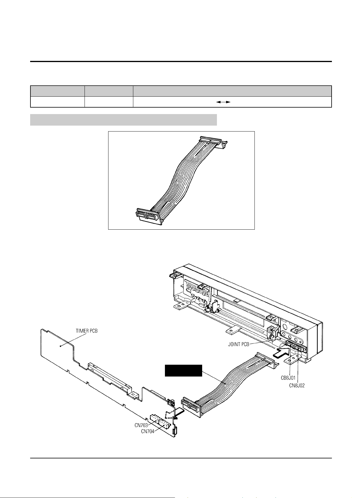
2-2 Servicing Jigs and Special Tools (Only for SV-7000W )
2-2-1 Servicing Jig
E/Cable
Jig Item
68140-500-104
Part No.
Use for Timer PCB (CN703, CN704) Joint PCB (CN8J01, CN8J02)
Use
2-2-2 How to Connection
E/CABLE
This is the same as the E/CABLE-2 used for Model SV-4000W.
Fig. 2-4
Fig. 2-5
 Loading...