

Page 1
Samsung Electronics
6-1
6. Alignment and Adjustment
6-1 Reference
1) X-Point (Tracking center) adjustment, “Head switching adjustment” and “NVRAM option setting” can be adjusted with remote control.
2) When replacing the Micom (IC601) and NVRAM (IC605 ; EEPROM) be sure to adjust the “Head switching adjustment” and
“NVRAM option setting”.
3) When replacing the cylinder ass’y, be sure to adjust the “X-Point” and “Head switching adjustment”.
4) Among Samsung VCR remote control used for adjustment as a accessory, only the remote control that has figures buttons (0 ~ 9) is
available for all adjustment regardless of chassis.
5) How to adjustment.
- Press the “TEST” (SV-7000W ; SW711, SV-5000W ; SW718) button on Timer PCB to set the adjustment mode.
- If the corresponding adjustment button is pressed, the adjustment is performed automatically.
- If the adjustment is completed, be sure to turn the power off.
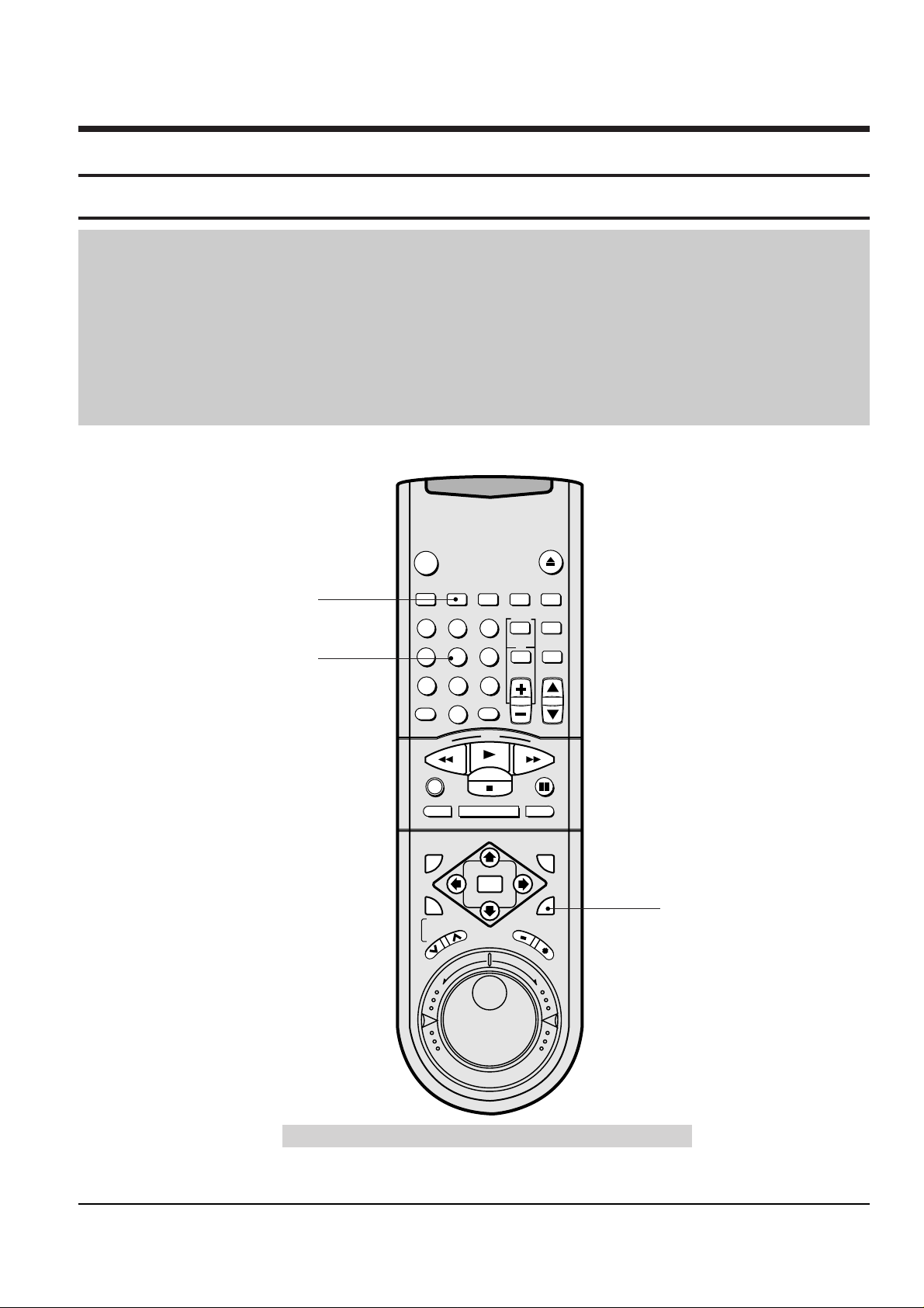
6-1-1 Location of adjustment button of remote control
Fig. 6-1
VCR
POWER
EJECT
INDEX REC.SPEED CLK/COUNT PICTURE TIMER
ART INPUT
1
2
3
4
5
6
7
8
9
0
CLR/RST
100
CH
R
E
W
P
L
A
Y
F
.
F
DISPLAY MONITOR A.DUB
REC
P/STILL
INPUT
SYSTEM
OUTPUT
SYSTEM
AUTO MENU
REV
FWD
STOP
STROBE AUDIO
OK
T
R
A
C
K
I
N
G
S
L
O
W
Remote Control for adjustment is not supplied as a Service Jig.
X-Point (Tracking Center)
Adjustment
Head Switching Adjustment
NVRAM Option Setting
Page 2
6-2
Samsung Electronics
Alignment and Adjustment
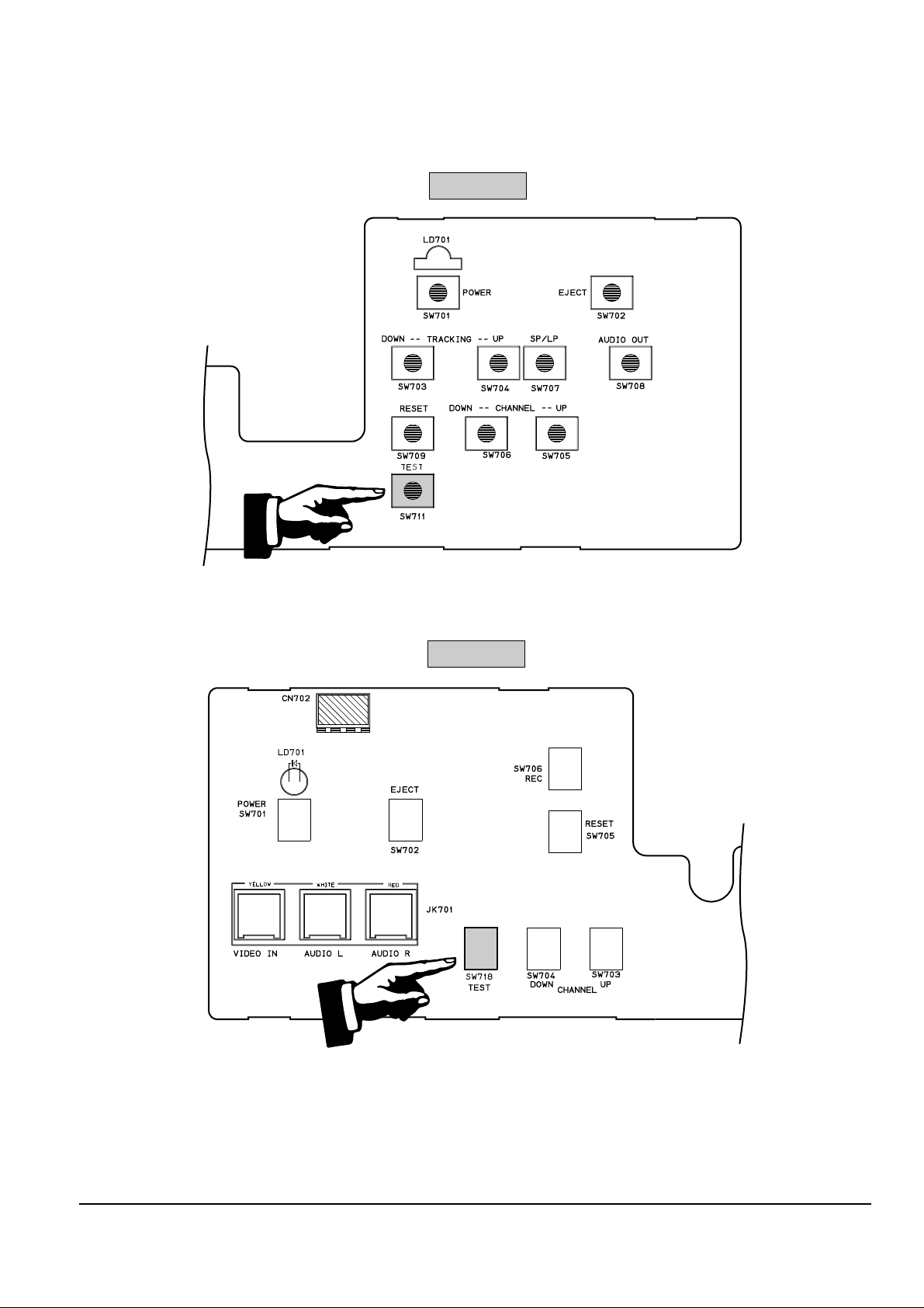
6-1-2 Test point location for adjustment mode setting
Fig. 6-2
(TIMER PCB ; Top View)
(F/TIMER PCB ; Top View)
SV-7000W
SV-5000W
Page 3

Alignment and Adjustment
Samsung Electronics
6-3
6-2 Mechanical Adjustment
Note : Refer to the Mechanical Manual ÒDX-9R (AC68-00001A)Ó for the adjustment and confirmation of
assÕy full deck.
6-2-1 The number and position of test point
Fig. 6-3 Location of Test point (Main PCB-Top View)
TP01
ENVELOPE
AUDIO OUTPUT
VIDEO OUTPUT
H'D S/W-Trigger
CONTROL PULSE
6-2-2 ACE Head Position (X-Point) Adjustment
(See the 2-2-1(d) ACE Head Position (X-Point) Adjustment
on page 2-2 of the Mechanical Manual)
1) Playback the alignment tape (Color bar).
2) Press the ÒTESTÓ (SV-7000W ; SW711, SV-5000W ;
SW718) button on Timer PCB to set the adjustment
mode. (See Fig. 6-2)
3) Press the Ò5Ó button of remote control then adjustment is operated automatically. (See Fig. 6-1)
4) Connect the CH-1 probe to TP01 (Envelope) the
CH-2 probe to TP01 (HÕD switching pulse) and
then trigger to CH-1.
5) Insert the (-) driver into the X-Point adjustment
hole and adjust it so that envelope waveform is
maximum.
6) Turn the Power off.
Page 4

6-4
Samsung Electronics
Alignment and Adjustment
6-3 Head Switching Point Adjustment
1) Playback the alignment tape.
2) Press the ÒTESTÓ (SV-7000W ; SW711, SV-5000W ; SW718) button on Timer PCB to set the adjustment
mode. (See Fig. 6-2)
3) Press the ÒREC.SPEEDÓ button of remote control then adjustment is operated automatically. (See Fig. 6-1)
4) Turn the Power off.
6-4 NTSC Skew Adjustment
1) Load the instrument with an alignment tape and playback the color bar signal (NTSC SP color bar tape).
2) Connect CH-1 scope probe (1V/div, 50µs/div.).
3) Connect CH-2 scope probe to video terminal of J4303 (I/O PCB).
4) Set the VCR to RPS (Reverse picture search) or FPS (Forward picture search) mode.
5) Adjust VR4301 (I/O PCB) so that the 100% white and pedestal is as flat as possible.
CORRESPOND TO LEVEL
(Before Adjustment) (After Adjustment)
Fig. 6-4 I/O PCB (Top View)
Page 5

Alignment and Adjustment
Samsung Electronics
6-5
6-5 NVRAM Option Setting
1) Press the ÒTESTÓ (SV-7000W ; SW711, SV-5000W ; SW718) button on Timer PCB to set the adjustment
mode. (See Fig. 6-2)
2) Press the ÒMENUÓ button on the remote control about 5 seconds then option setting display is appeared.
(See Fig. 6-5)
3) Select the option number (See Table 6-1) of corresponding model with Ò Ò and Ò Ò button on the remote
control.
4) If selecting the option number is completed, press the Ò Ó button of remote control.
(If ÒSTOPÓ button is pressed, the selected number is changes reversed color. ; See Fig. 6-5)
5) Press the ÒOKÓ button of remote control again to store the option number.
(ÒPLEASE WAITÓ is displayed for a second as shown Fig. 6-6 and this setting is completed.)
6) Turn the Power off.
1) NVRAM Option is adjusted at production line basically.
2) In case Micom (IC601) and NVRAM (IC605 ; EEPROM) is replaced, be sure to set the corresponding option number of the repaired
model. (If the option is not set, the unit is not operated.)
01 02 03 04 05 06 07 08
09 10 11 12 13 14 15 16
17 18 19 20 21 22 23 24
25 26 27 28 29 30 31 32
33 34 35 36 37 38 39 40
41 42 43 44 45 46 47 48
**
OPTION DIODE
**
CNG : SAVE : OK
Fig. 6-5
01 02 03 04 05 06 07 08
09 10 11 12 13 14 15 16
17 18 19 20 21 22 23 24
25 26 27 28 29 30 31 32
33 34 35 36 37 38 39 40
41 42 43 44 45 46 47 48
**
OPTION DIODE
**
CNG : SAVE : OK
PLEASE WAIT
Fig. 6-6
MODELS TV SYSTEM OPTION NUMBER
SV-7000W NTSC/PAL 1, 2, 3, 4, 5, 6, 9, 10, 11, 13, 14, 15, 16
SV-5000W
NTSC 1, 2, 3, 4, 6, 8, 13, 14, 15
PAL 1, 2, 3, 4, 5, 9, 10, 11, 13, 14, 15
<Table 6-1>
Page 6

6-6
Samsung Electronics
Alignment and Adjustment
MEMO
 Loading...