

Samsung Svr-600, sv-605G, SV-A120G-CIS Alignment and Adjustments
Samsung Electronics 5-1
5. Alignment and Adjustment
Note : After replacing the assÕy full deck, the assÕy main, the cylinder assÕy and the micom(IC601), the remote
control assÕy can be used to adjust the ÒX-point (tracking center) adjustmentÓ and ÒHead S/W pointÓ
adjustment.
5-1 Reference
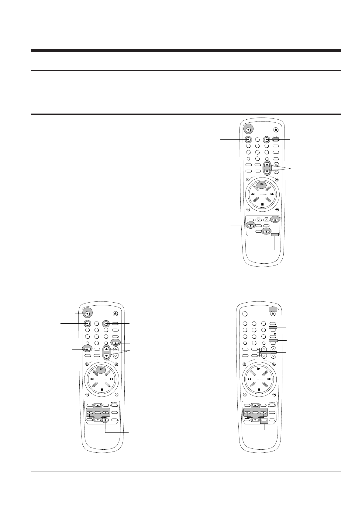
5-1-1 The type of remote control ass’y
1. Remote control assÕy (AC93-10039Y/69099-633-252)
is specified as a service jig in the service manual of
X-5/X-6(DX5-R/DX5-RC/DX6-R/DX6-RC) chassis.
(See Fig. 5-1)
2. Normal remote control assÕy for X-7/X-8
(DX7-R/DX7-RC/DX8-R/DX8-RC) chassis.
(See Fig. 5-2)
5-1-2 How to identify between normal
remote control ass’y and multi
remote control ass’y for X-7/X-8
chassis (See Fig. 5-2)
1. The color of some buttons related to TV function are
gold.
2. Audio button is added instead of the test button
hidden behind of inlay.
3. The positions of some buttons are different.
EJECT
2
45 6
789
0
CLK/COUNT
REW
F.F
STOP
CLR/RST DISPLAY
Q-PRO
MENU
S
H
I
F
T
S
H
U
T
T
L
E
DAILY WEEKLY
REC
P/S
PRESET BAND
SEARCH MEMORY
OUTPUT
INDEX SLOW INPUT
INPUT BUTTON
SP/LP BUTTON
SP LP A.DUB VPS
FINE CH
TRK
(TRACKING, FINE)
BUTTON
POWER BUTTON
POWER
PLAY BUTTON
PLAY
TEST BUTTON IS
HIDDEN BEHIND
OF INLAY.
3
HEAD S/W ADJ.
("INPUT" OR "TEST"
AND "3" BUTTON)
1
TRACKING
CENTER ADJ.
("INPUT" OR "TEST"
AND "1" BUTTON)
633-252
REMOTE CONTROL
ASS'Y PART NO.
Fig. 5-1 Remote Control Ass’y Jig for X-5/X-6 Chassis
(AC93-10039Y/69099-633-252)
EJECT
2
45 6
789
0
CLK/COUNT
REW
F.F
STOP
AUDIO
DISPLAY
REC
P/S
INDEX A.TRK
INPUT BUTTON
FINE PROG
TRK
(TRACKING, FINE)
BUTTON
POWER BUTTON
POWER
PLAY BUTTON
PLAY
TEST BUTTON IS
HIDDEN BEHIND
OF INLAY.
3
HEAD S/W ADJ.
("INPUT" OR "TEST"
AND "3" BUTTON)
1
TRACKING
CENTER ADJ.
("INPUT" OR "TEST"
AND "1" BUTTON)
SYSTEM
CLR/RST
S
H
U
T
T
L
E
SPEED BUTTON
SPEED AFT
INPUT
TV/VCR
PICTURE
A.DUB
2
45 6
789
0
CLK/COUNT
REW
F.F
STOP
DISP./
REC
P/S
INDEX
VCR
POWER
PLAY
3
1
VCR
CLR/RST
S
H
U
T
T
L
E
SPEED
TV/VCR
PICTURE
A.DUB
NORMAL REMOTE CONTROL ASS'Y
(CAN ADJUST)
MULTI REMOTE CONTROL ASS'Y
(CAN NOT ADJUST)
-/--
FINE
AUDIO
ADD BUTTON(AUDIO)
GOLD COLOR
TV
GOLD COLOR
TV
POWER
INPUT
GOLD COLOR
VOLUME PROG
GOLD COLOR
MENU
Q-PRO
SLOW
SOFTEN OK SHARPEN
MENU
Q-PRO
SLOW
SOFTEN OK SHARPEN
Fig. 5-2 Remote Control Ass’y for X-7/X-8 Chassis
Alignment and Adjustment
5-2 Samsung Electronics
5-2 Mechanical Adjustment
Note : Refer to the Mechanical Manual ÒDX7-R/DX7-RC/DX8-R/DX8-RC (AC68-20316A)Ó for the adjustment
and confirmation of assÕy full deck.
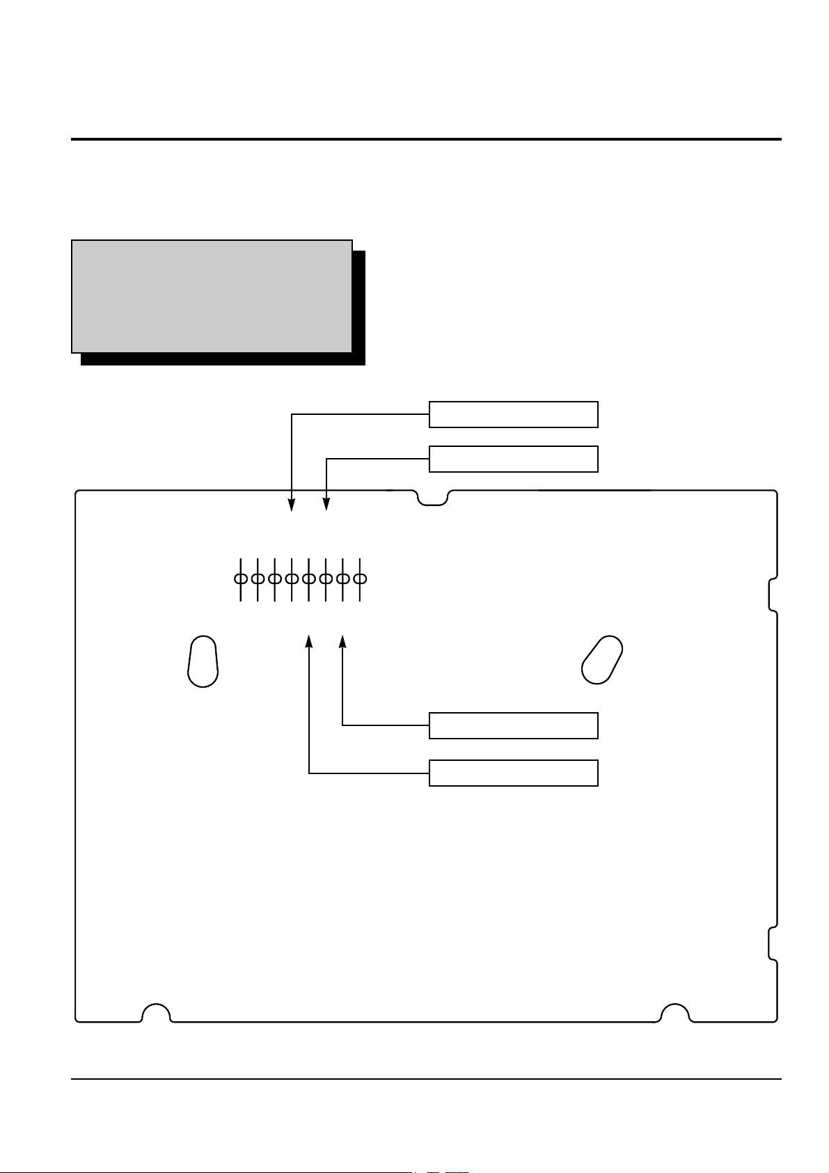
5-2-1 The number and position of test point
GND
CTL
TP01
H'D SW
V.ENV
A.OUT
V.OUT
AGC
SCART CTL
TP02
TP03
TP04
TP05
TP06
TP07
TP08
Fig. 5-3 The position of test point (Main PCB-Component side)
Test point : TP02 (CTL Pulse)
TP03 (H’D S/W -Trigger)
TP04 (V. Envelope)
TP05 (Audio out)
CTL PULSE
V. ENVELOPE
AUDIO OUT
H’D S/W -TRIGGER
Alignment and Adjustment
Samsung Electronics 5-3
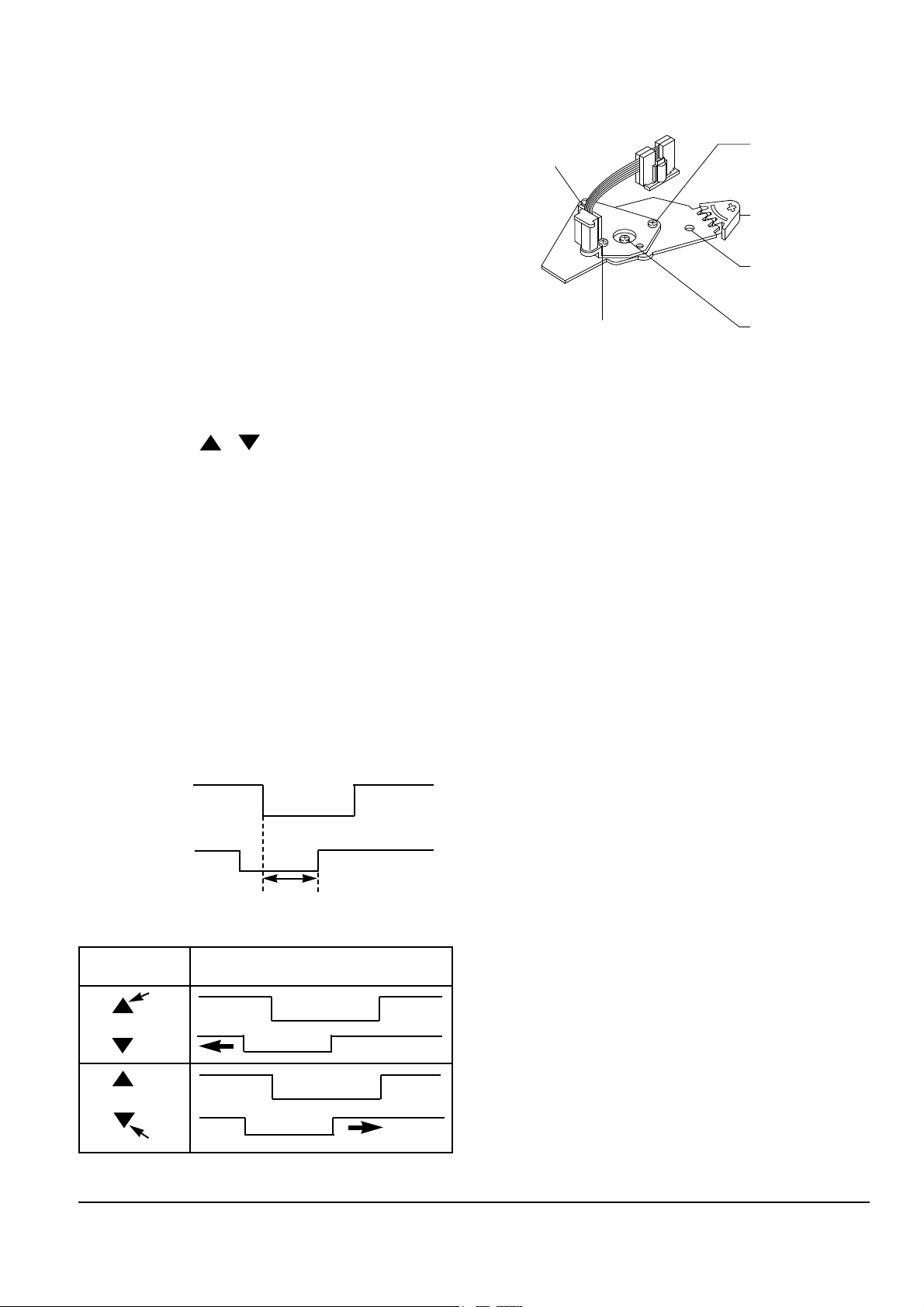
5-2-2 X-Point(Tracking center) adjustment
(See the 2-2-1 (d) AC HEAD
POSITION(X-POINT) ADJUSTMENT
on page 2-3 of the mechanical
manual)
5-2-2 (a) IF THE REMOTE CONTROL ASS’Y IS
NOT AVAILABLE
1. Playback the colorbar alignment tape.
2. Connect CH-1 scope probe to ÒTP02Ó and CH-2
scope probe to ÒTP03Ó. And then, trigger head
switching pulse.
3. Set tracking preset to 11msec (2head : 2.7msec,
4, 6head : 11msec) using the ÒFINE(Tracking,
TRK)Ó button / of the other remote control
assÕy except the remote control assÕy jig for X-5/
X-6 chassis and the normal remote control assÕy for
X-7/X-8 chassis.
4. Connect CH-1 scope probe to ÒTP02Ó and the CH-2
to ÒTP03Ó trigger on CH-1.
5. Insert the adjusting driver (+) into X-position
adjusting gear. Adjust the driver in either direction
for maximum envelope waveform.
Note :
Since the adjusting gear unit may be damaged, do
not adjust by force when adjusting the X-point using the
adjusting driver (+). After turn the X-point adjusting screw
(D) counterclockwise a little, perform the adjustment.
After adjustment is completed, tighten the screw.
5-2-2 (b) IF THE REMOTE CONTROL ASS’Y
(AC93-10039Y/69099-633-252) IS
AVAILABLE
Note : How to use the ÒTESTÓ button.
1. Disattach the inlay of remote control assÕy.
(See Fig. 5-1 and Fig. 5-2)
2. Press the ÒTESTÓ button with the pincers and the
precise driver as shown in Fig. 5-1 and 5-2)
1. When using the ÒINPUTÓ button of remote
control assÕy;
1) Simultaneously press the ÒINPUTÓ button and Ò1Ó
button in PB mode.
This will adjust the tracking center automatically.
2) Set the tracking preset using the ÒFINE(Tracking,
TRK)Ó button of remote control.
3) After adjustment is completed, press the
ÒPOWERÓ button to release.
2. When using the ÒTESTÓ button of remote
control assÕy ;
1) Simultaneously press the ÒTESTÓ button and Ò5Ó
button in PB mode.
This will adjust the tracking center automatically.
2) Set the tracking preset using the ÒFINE (Tracking,
TRK) button of remote control.
3) After adjustment is completed, press the
ÒPOWERÓ button to release.
<Setting of scope>
- Volt/div. : CH-1 = 0.1V - Time/div. : 5msec
CH-2 = 0.2V
CH-2 Probe
TP02
H’D S/W Pulse
CH-1 Probe
TP03
CTL Pulse
Fig. 5-4 Tracking preset adjustment
REMOTE
BUTTONS
TRACKING
TRACKING
CONTROL PULSE REMOVE
PUSH
PUSH
Fig. 5-5 Tracking preset adjustment
SCREW(C)
TILT ADJUST
X-POSITION
ADJUST GEAR
HOLE
SCREW(A)
HEIGHT ADJUST
SCREW(B)
AZIMUTH ADJUST
SCREW(D)
X-POINT LOCKING
Fig. 5-6 Location of A/C Head adjustment screw
2.7msec(2 head), 11msec(4, 6 head)
 Loading...