

SAMSUNG SV5000WXAA Service Manual
VIDEO CASSETTE RECORDER
SV-7000W
SV-5000W
SERVICE
1. Precautions
2. Reference Information
3. Product Specifications
4. Disassembly and Reassembly
5. Troubleshooting
6. Alignment and Adjustment
7. Exploded View and Parts List
8. Electrical Parts List
9. Block Diagram
10. PCB Diagrams
11. Wiring Diagram
12. Schematic Diagrams
Manual
VIDEO CASSETTE RECORDER CONTENTS
For mechanical disassembly and adjustment, refer to the “Mechanical Manual” (DX-9R AC68-00001A).
SERVICE MANUAL SV-7000W/SV-5000W
ELECTRONICS
© Samsung Electronics Co., Ltd. SEP. 1999
Printed in Korea
AC68-00434A
SV-7000W
SV-5000W
Samsung Electronics 1-1
1. Precautions
1. Be sure that all of the built-in protective devices are
replaced. Restore any missing protective shields.
2. When reinstalling the chassis and its assemblies, be
sure to restore all pretective devices, including :
control knobs and compartment covers.
3. Make sure that there are no cabinet openings
through which people--particularly children
--might insert fingers and contact dangerous
voltages. Such openings include the spacing
between the picture tube and the cabinet mask,
excessively wide cabinet ventilation slots, and
improperly fitted back covers.
If the measured resistance is less than 1.0 megohm
or greater than 5.2 megohms, an abnormality exists
that must be corrected before the unit is returned
to the customer.
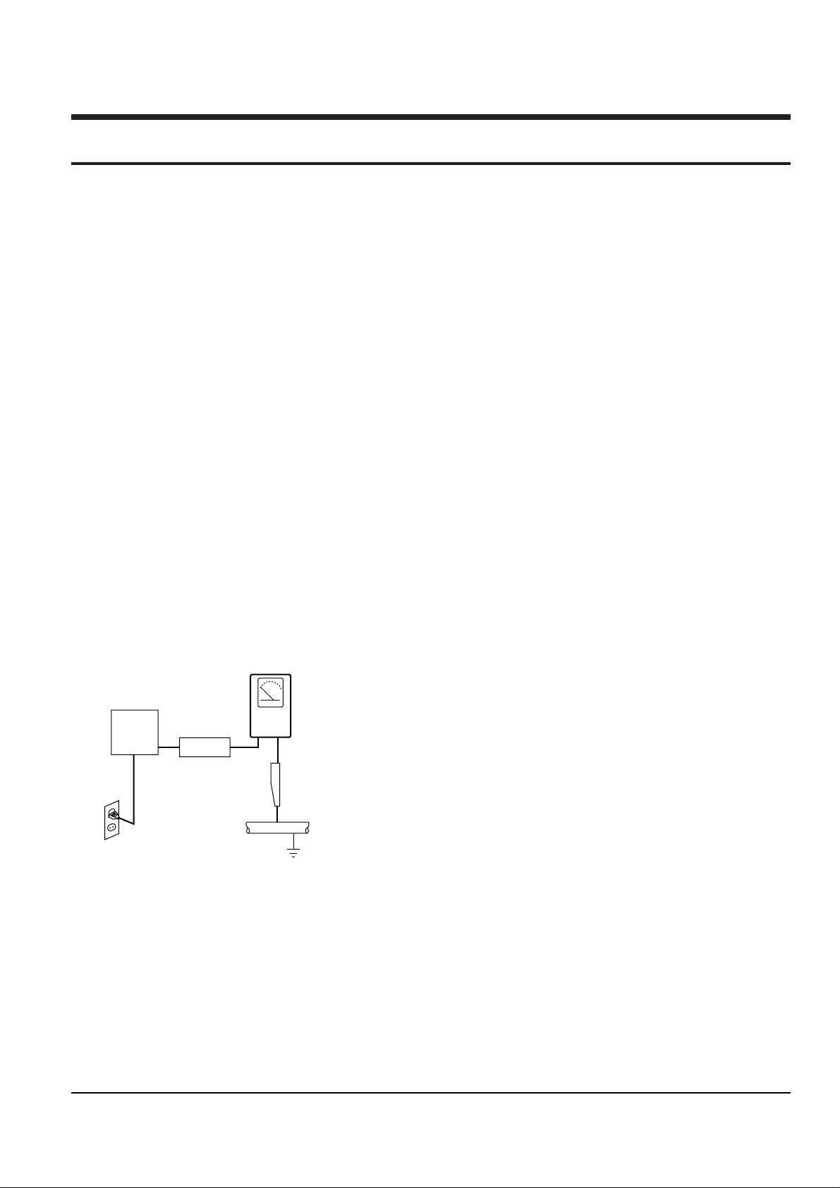
4. Leakage Current Hot Check (See Fig. 1-1) :
Warning : Do not use an isolation transformer
during this test. Use a leakage current tester or a
metering system that complies with American
National Standards Institute (ANSI C101.1,
Leakage Current for Appliances), and Underwriters
Laboratories (UL Publication UL1410, 59.7).
Fig. 1-1 AC Leakage Test
5. With the unit completely reassembled, plug the AC
line cord directly the power outlet. With the unitÕs
AC switch first in the ON position and then OFF,
measure the current between a known erath
ground (metal water pipe, conduit, etc.) and all
exposed metal parts, including : antennas, handle
brackets, metal cabinets, screwheads and control
shafts. The current measured should not exceed
0.5 milliamp. Reverse the power-plug prongs in the
AC outlet and repeat the test.
6. Antenna Cold Check :
With the unitÕs AC plug disconnected from the
AC source, connect an electrical jumper across the
two AC prongs. Connect one lead of the ohmmeter
to an AC prong.
Connect the other lead to the coaxial connector.
7. Some semiconductor (Òsolid stateÓ) devices are
easily damaged by static electricity.
Such components are called Electrostatically
Sensitive Devices (ESDs); examples include
integrated circuits and some field-effect transistors.
The following techniques will reduce the
occurrence of component damage caused by static
electricity.
8. Immediately before handling sny semiconductor
components or assemblies, drain the electrostatic
charge from your body by touching a known
earth ground. Alternatively, wear a discharging
Wrist-strap device. (Be sure to remove it prior to
applying power--this is an electric shock
precaution.)
9. Design Alteration Warning :
Never alter or add to the mechanical or electrical
design of this unit. Example : Do not add
auxiliary audio or video connectors.
Such alterations might create a safety hazard.
Also, any design changes or additions will void
the manufacturerÕs warranty.
10. Never defeat any of the B+ voltage interlocks.
Do not apply AC power to the unit (or any of its
assemblies) unless all solid-state heat sinks are
correctly installed.
DEVICE
UNDER
TEST
(READING SHOULD
NOT BE ABOVE
0.5mA)
LEAKAGE
CURRENT
TESTER
EARTH
GROUND
TEST ALL
EXPOSED METER
SURFACES
ALSO TEST WITH
PLUG REVERSED
(USING AC ADAPTER
PLUG AS REQUIRED)
2-WIRE CORD

Precautions
1-2 Samsung Electronics
11. Always connect a test instrumentÕs ground lead to
the instrument chassis ground before connecting
the positive lead; always remove the instrumentÕs
ground lead last.
12. Observe the original lead dress, especially near
the following areas : Antenna wiring, sharp
edges, and especially the AC and high voltage
power supplies. Always inspect for pinched, outof-place, or frayed wiring. Do not change the
spacing between components and the printed
circuit board. Check the AC power cord for
damage. Make sure that leads and components
do not touch thermally hot parts.
13. Product Safety Notice :
Some electrical and mechanical parts have special
safety-related characteristics which might not be
obvious from visual inspection. These safety
features and the protection they give might be
lost if the replacement component differs from the
original--even if the replacement is rated for
higher voltage, wattage, etc.
Components that are critical for safety are
indicated in the circuit diagram by shading,
( or ).
Use replacement components that have the same
ratings, especially for flame resistance and
dielectric strength specifications. A replacement
part that does not have the same safety
characteristics as the original might create shock,
fire or other hazards.
Samsung Electronics 2-1
2. Reference Information
2-1 Important Service Guide
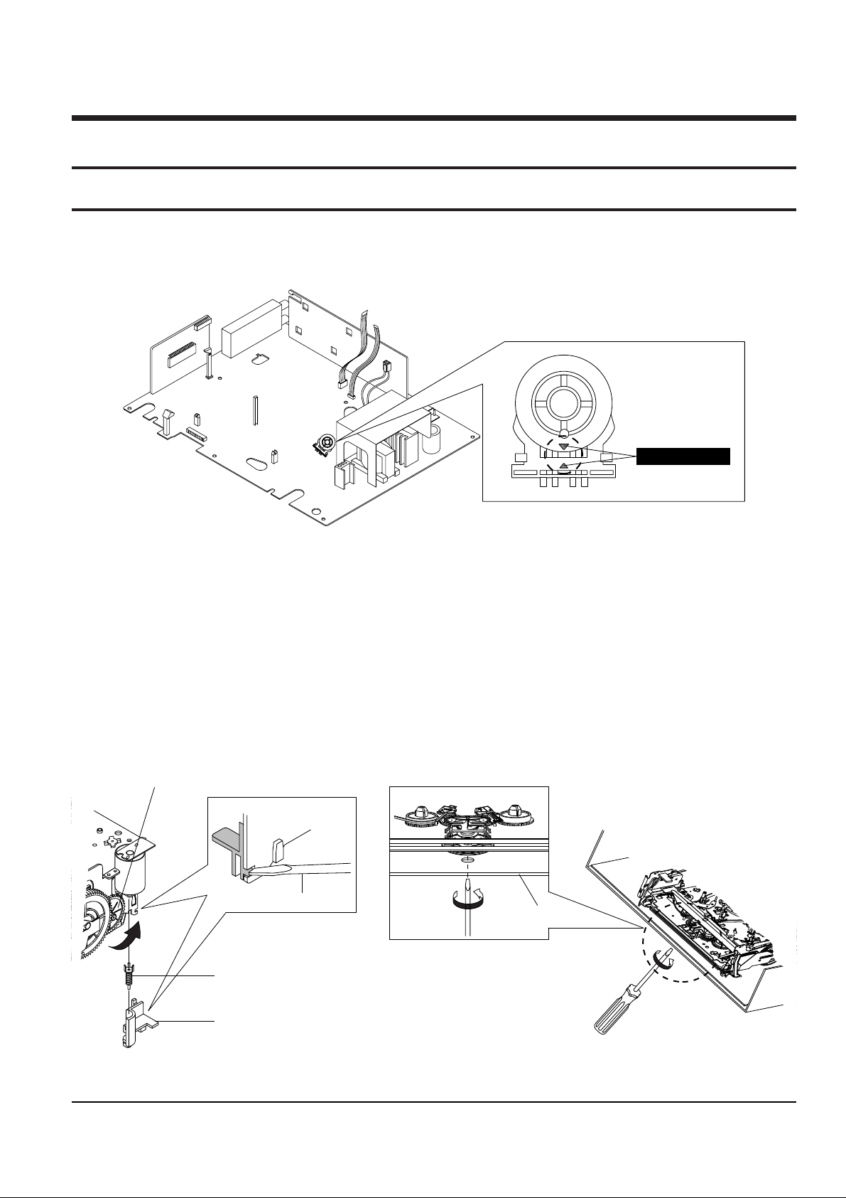
2-1-1 Mode switch (Program Switch) assembly point
1) When installing the assÕy full deck on the Main PCB, be sure to align the assembly point of mode switch.
2-1-2 How to eject the cassette tape
(If the unit does not operate on condition that tape is inserted into housing ass’y)
1) Remove the Holder Worm Œ and the gear worm ´. (See Fig. 2-2)
2) Turn the Gear Worm Wheel ˇ counterclockwise in the direction of arrow with screw driver. (See Fig. 2-2)
3) When Slider S, T are approached in the position of unloading, rotate holder Clutch counterclockwise after
inserting screw driver in the hole of frameÕs bottom in order to wind the unwounded tape. (Refer to Fig. 2-3)
(If you rotate Gear Worm Wheel continuously when tape is in state of unwinding, you may cause a tape conta
mination by grease and tape damage. Be sure to wind the unwounded tape in the state of set horizontally.)
4) Rotate Gear Worm Wheel ˇ counterclockwise using screw driver again up to the state of eject mode and then
pick out the tape. (Refer to Fig. 2-2)
Fig. 2-2 Fig. 2-3
ΠHOLDER WORM
´ GEAR WORM
SCREW DRIVER
ˇ GEAR WORM WHEEL
FRAME
ASSEMBLY POINT
Fig. 2-1
Reference Information
2-2 Samsung Electronics
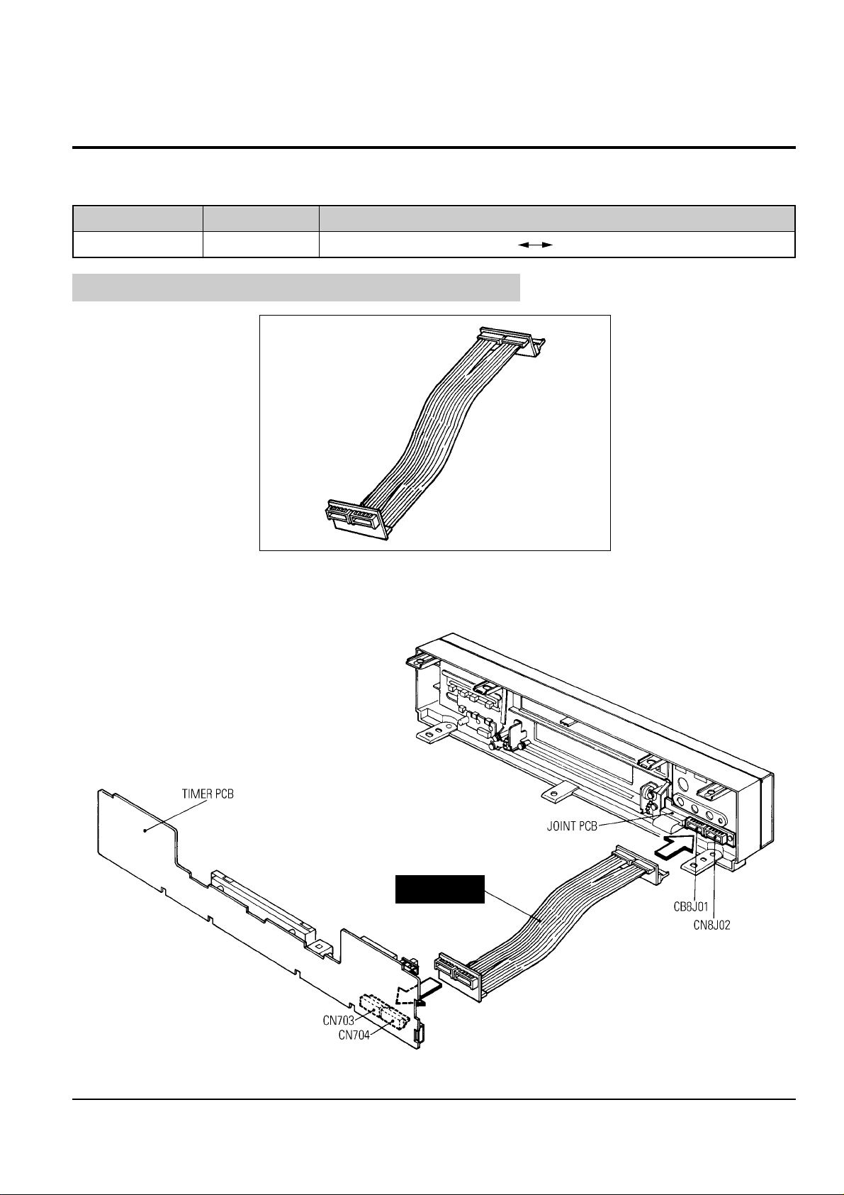
2-2 Servicing Jigs and Special Tools (Only for SV-7000W )
2-2-1 Servicing Jig
E/Cable
Jig Item
68140-500-104
Part No.
Use for Timer PCB (CN703, CN704) Joint PCB (CN8J01, CN8J02)
Use
2-2-2 How to Connection
E/CABLE
This is the same as the E/CABLE-2 used for Model SV-4000W.
Fig. 2-4
Fig. 2-5
Samsung Electronics 3-1
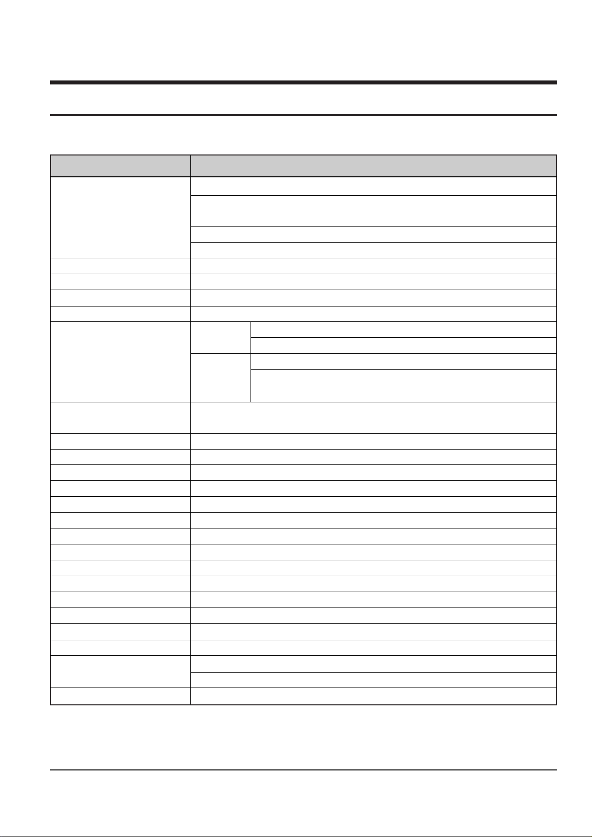
3. Product Specifications
Design and specifications are subject to change without notice.
Operation Description
Recording system Rotary head azimuth recording, luminance signal FM recording system
Crominance signal down converted phase shift recording system
(NTSC, PAL, PAL-M)
Chrominance signal down converted direct recording system (MESECAM)
Chrominance signal 1/4 frequency countdown direct recording system (SECAM)
Color system NTSC3.58, NTSC4.43, PAL, PAL-M, PAL-N, SECAM
Tuning system SV-7000W/5000W ; B/G, D/K, I, M, N, L SV-5000W NTSC System ; B/G, D/K, I, M, N
RF out
SV-7000W/5000W ; G/I/K/M/L, UHF CH21-CH69 SV-5000W NTSC System ; G/I/K/M, UHF CH21-CH69
Tape recording/playback NTSC, PAL, PAL-M, SECAM, MESECAM
Tape speed NTSC 33.35mm/sec (standard recording : SP)
PAL-M 11.12mm/sec (three times recording : SLP)
PAL 23.39mm/sec (standard recording : SP)
MESECAM
11.69mm/sec (double speed recording : LP)
SECAM
Tape format VHS type video tape, S-VHS type video tape (Playback only)
Recording time Maximum 8 hours (with a T-160 tape or E-240tape)
Rewinding time within 3 minutes (high speed rewinding, T-120 or E-180 tpae)
Video input 1.0Vp-p (unbalanced) 75 ohm
Video output 1.0Vp-p (unbalanced) 75 ohm
Video S/N Above 43dB (standard recording)
Resolution Above 220 (standard recording NTSC), 240 (standard recording PAL)
Audio input -8dBm, 47 Kohm unbalanced
Audio output -8 +/- 3 dBm, 1 Kohm unbalanced
Audio S/N Above 39dB (Mono), 68dB (Hi-Fi)
Audio frequency characteristics 20Hz-20KHz
Rated voltage 100V~240V AC, 100V AC (JAPAN)
Rated frequency 50/60Hz
Power consumption ARP. 24 watts on recording ; 8 watts off
Working ambient temperature 41°F-104°F (5°C-40°C)
Installation conditions Operation position : Horizontal, Relative humidity : Below 80%
Outside dimensions SV-7000W : Width 465mm X Length 310mm X Height 98mm
SV-5000W : Width 430mm X Length 295mm X Height 98mm
Weight SV-7000W : 4.8Kg SV-5000W : 4.3Kg

Product Specifications
3-2 Samsung Electronics
MEMO
Samsung Electronics 4-1
4. Disassembly and Reassembly
4-1 Cabinet Assembly
Note : Disassemble in the order shown. Reassemble in reverse order.
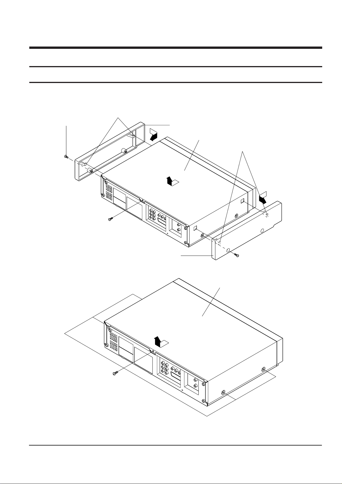
4-1-1 Cabinet Top removal
"B"
"A"
´ REMOVE 1 SCREW.
(BH;5-4X16-BLOCK)
ˇ RELEASE 2 HOOKS.
ΠREMOVE 1 SCREW.
(BH;5-4X16-BLOCK)
"C"
¨ REMOVE THE PANEL-SIDE(L) IN THE DIRECTION OF ARROW "A".
ˆ REMOVE 1 SCREW.
(BH;5-4X16-BLOCK)
Ø RELEASE 2 HOOKS.
∏ REMOVE THE PANEL-SIDE(R) IN THE DIRECTION OF ARROW "B".
” LIFT UP THE CABINET-TOP
IN THE DIRECTION OF ARROW "C".
ΠREMOVE 5 SCREWS.
(BH;5-4X16-BLOCK)
´ LIFT UP THE CABINET-TOP
IN THE DIRECTION OF ARROW .
<SV-7000W>
<SV-5000W>
Fig. 4-1 Cabinet Top removal
Disassembly and Reassembly
4-2 Samsung Electronics
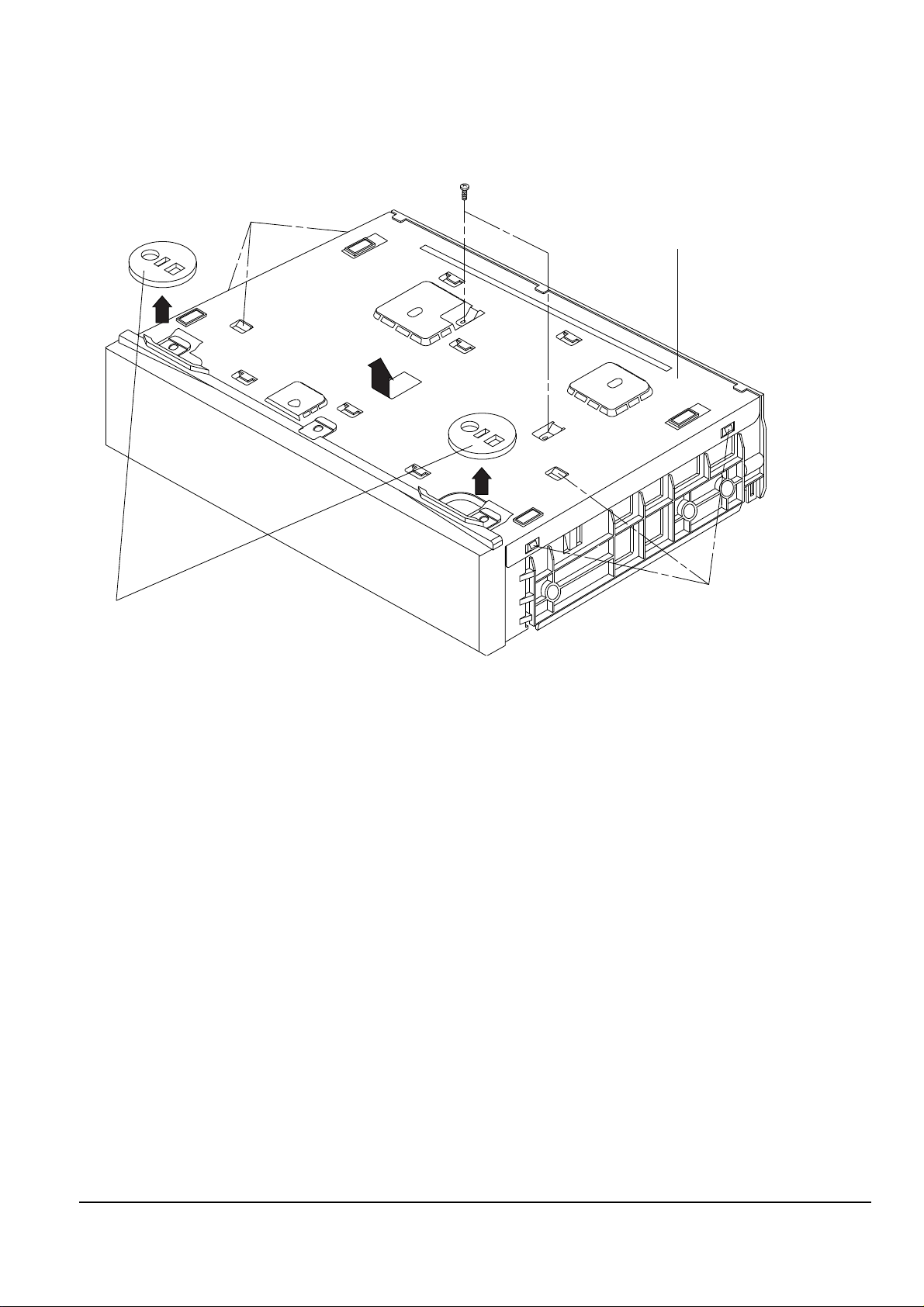
4-1-2 Bottom Cover removal
ΠREMOVE 2 SCREWS.
(BH;2-3X10-YELLOW)
ˇ RELEASE 3 TABS.
¨ RELEASE 3 TABS.
"B"
"A"
"A"
ˆ LIFT UP THE BOTTOM-COVER
IN THE DIRECTION OF ARROW "B".
´ REMOVE THE DECORATION-LEG IN THE
DIRECTION OF ARROW "A".
Fig. 4-2 Bottom Cover removal
Disassembly and Reassembly
Samsung Electronics 4-3
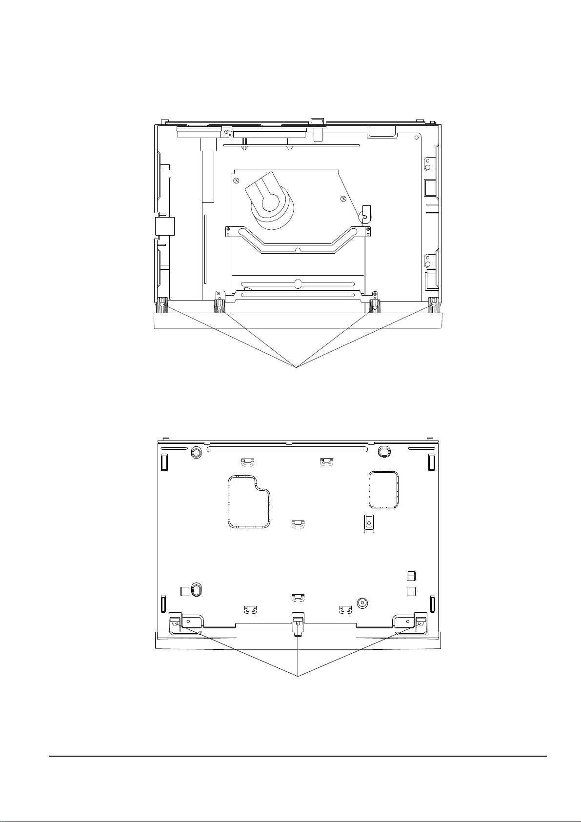
4-1-3 Ass’y Front Panel removal
ΠRELEASE 4 HOOKS.
´ RELEASE 3 HOOKS.
(Top view)
(Bottom view)
Fig. 4-3 Ass’y Front Panel removal
Disassembly and Reassembly
4-4 Samsung Electronics
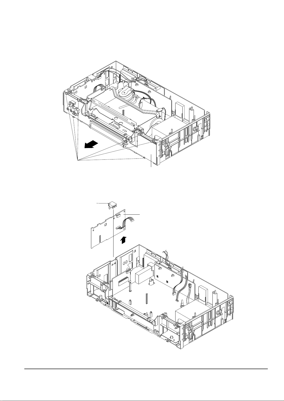
4-1-4 Ass’y Timer removal
Note : Take extreme care not to damage the PCB when removing it.
Fig. 4-4 Ass’y Timer removal
ΠRELEASE 6 HOOKS.
"A"
´ REMOVE THE ASS'Y FUNCTION IN THE DIRECTION OF ARROW "A".
ΠREMOVE HOLDER PCB.
´ LIFT UP THE ASS'Y DIGITAL IN THE DIRECTION OF ARROW.
4-1-5 Ass’y Digital removal
Fig. 4-5 Ass’y Digital removal
Disassembly and Reassembly
Samsung Electronics 4-5
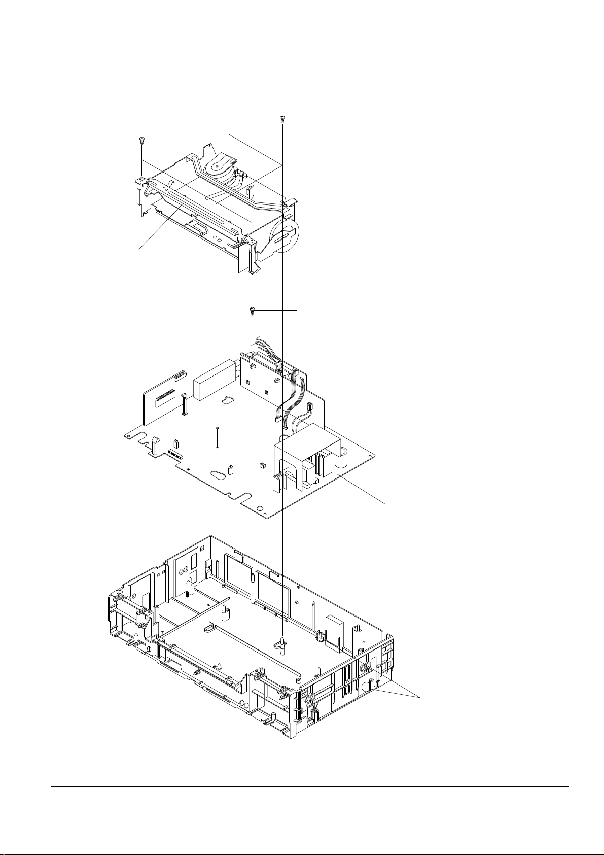
4-1-6 Chassis Unit removal
Fig. 4-6 Chassis Unit removal
ΠREMOVE 2 SCREWS.
´ REMOVE BRACKET-FRAME.
ˇ REMOVE 3 SCREWS.
¨ LIFT THE ASS'Y FULL DECK UP.
ˆ REMOVE 1 SCREW.
Ø RELEASE 2 TABS.
∏ LIFT THE ASS'Y MAIN PCB UP TO REMOVE.
Disassembly and Reassembly
4-6 Samsung Electronics
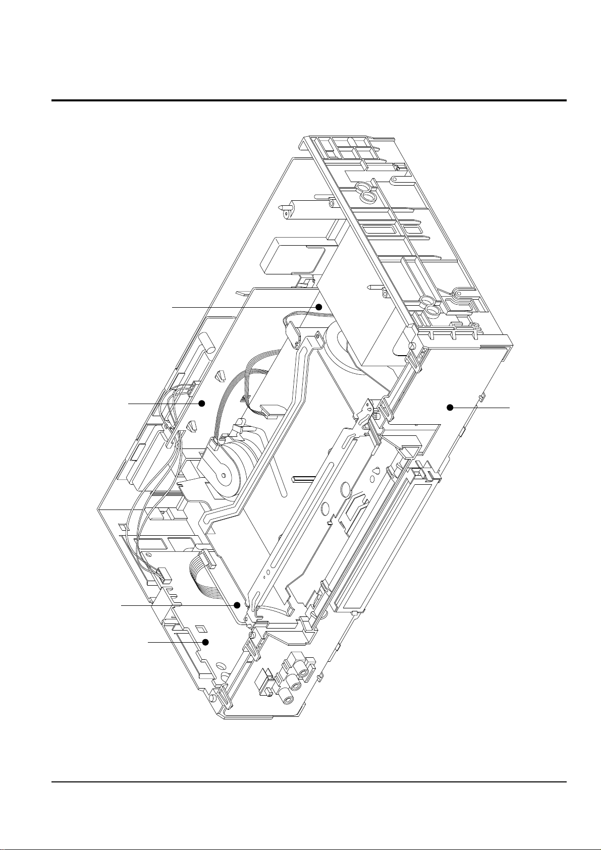
4-2 Circuit Board Locations
TIMER PCB
DIGITAL PCB
I/O PCB
MAIN PCB
A2/NICAM PCB
(STEREO/BILINGUAL)
Fig. 4-7 Circuit Board Locations
Samsung Electronics
6-1
6. Alignment and Adjustment
6-1 Reference
1) X-Point (Tracking center) adjustment, “Head switching adjustment” and “NVRAM option setting” can be adjusted with remote control.
2) When replacing the Micom (IC601) and NVRAM (IC605 ; EEPROM) be sure to adjust the “Head switching adjustment” and
“NVRAM option setting”.
3) When replacing the cylinder ass’y, be sure to adjust the “X-Point” and “Head switching adjustment”.
4) Among Samsung VCR remote control used for adjustment as a accessory, only the remote control that has figures buttons (0 ~ 9) is
available for all adjustment regardless of chassis.
5) How to adjustment.
- Press the “TEST” (SV-7000W ; SW711, SV-5000W ; SW718) button on Timer PCB to set the adjustment mode.
- If the corresponding adjustment button is pressed, the adjustment is performed automatically.
- If the adjustment is completed, be sure to turn the power off.
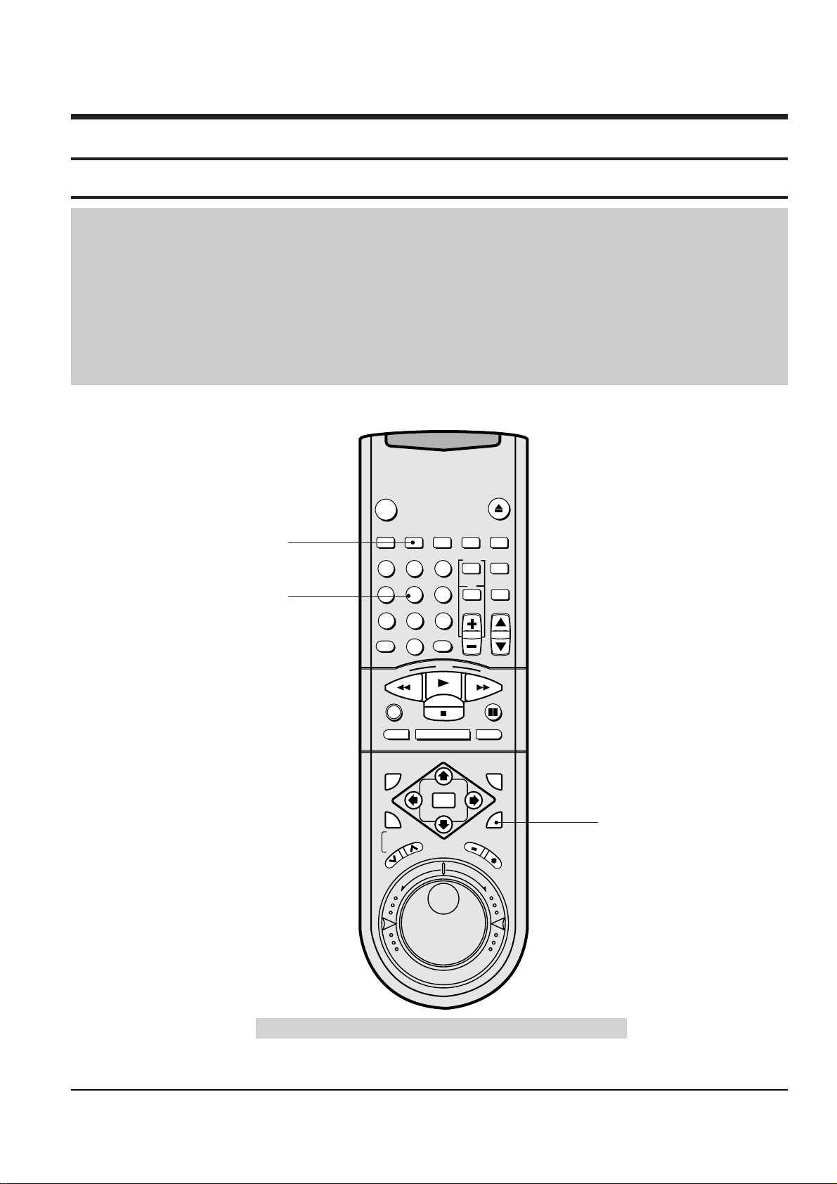
6-1-1 Location of adjustment button of remote control
Fig. 6-1
VCR
POWER
EJECT
INDEX REC.SPEED CLK/COUNT PICTURE TIMER
ART INPUT
1
2
3
4
5
6
7
8
9
0
CLR/RST
100
CH
R
E
W
P
L
A
Y
F
.
F
DISPLAY MONITOR A.DUB
REC
P/STILL
INPUT
SYSTEM
OUTPUT
SYSTEM
AUTO MENU
REV
FWD
STOP
STROBE AUDIO
OK
T
R
A
C
K
I
N
G
S
L
O
W
Remote Control for adjustment is not supplied as a Service Jig.
X-Point (Tracking Center)
Adjustment
Head Switching Adjustment
NVRAM Option Setting

6-2
Samsung Electronics
Alignment and Adjustment
6-1-2 Test point location for adjustment mode setting
Fig. 6-2
(TIMER PCB ; Top View)
(F/TIMER PCB ; Top View)
SV-7000W
SV-5000W
Alignment and Adjustment
Samsung Electronics
6-3
6-2 Mechanical Adjustment
Note : Refer to the Mechanical Manual ÒDX-9R (AC68-00001A)Ó for the adjustment and confirmation of
assÕy full deck.
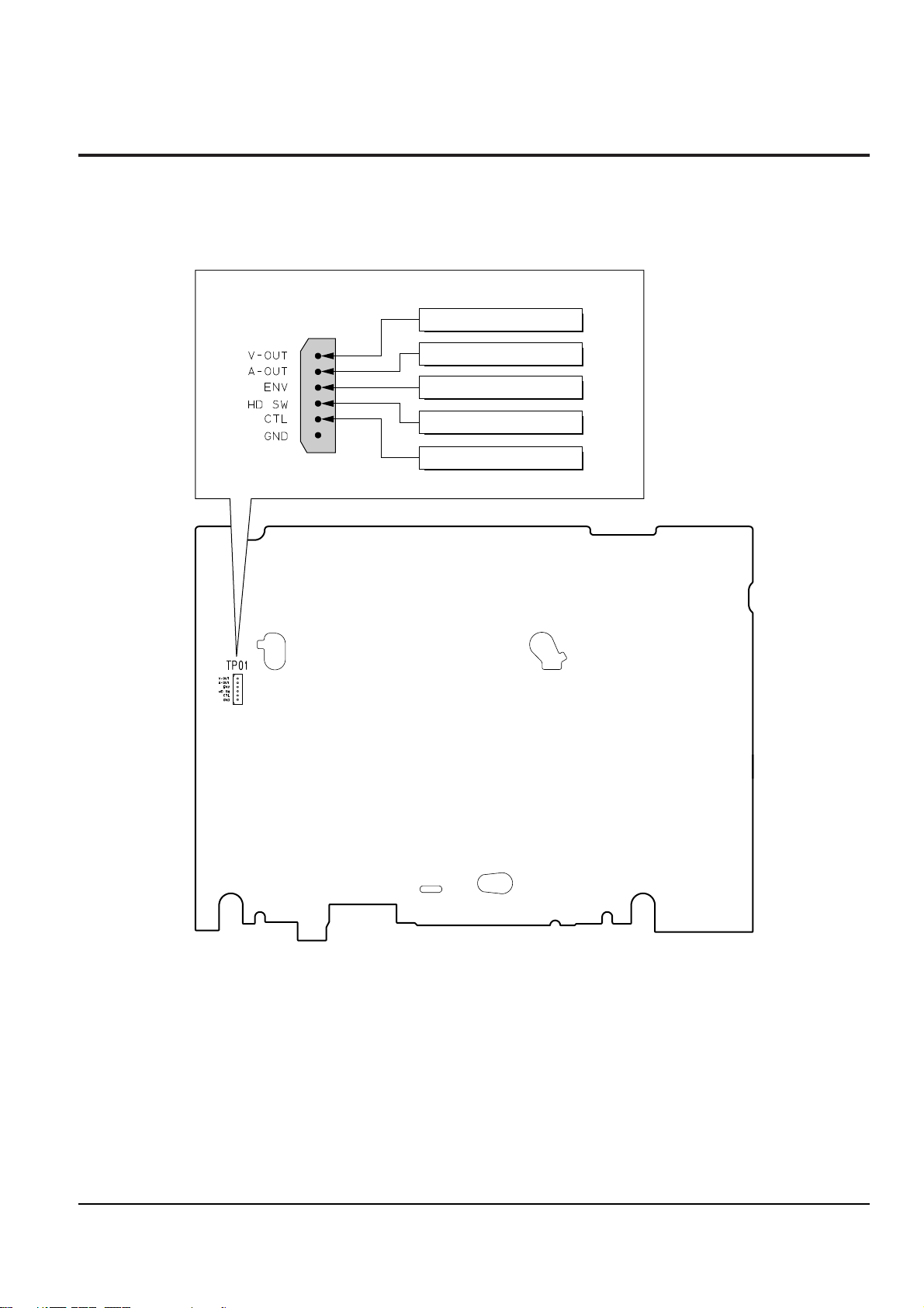
6-2-1 The number and position of test point
Fig. 6-3 Location of Test point (Main PCB-Top View)
TP01
ENVELOPE
AUDIO OUTPUT
VIDEO OUTPUT
H'D S/W-Trigger
CONTROL PULSE
6-2-2 ACE Head Position (X-Point) Adjustment
(See the 2-2-1(d) ACE Head Position (X-Point) Adjustment
on page 2-2 of the Mechanical Manual)
1) Playback the alignment tape (Color bar).
2) Press the ÒTESTÓ (SV-7000W ; SW711, SV-5000W ;
SW718) button on Timer PCB to set the adjustment
mode. (See Fig. 6-2)
3) Press the Ò5Ó button of remote control then adjustment is operated automatically. (See Fig. 6-1)
4) Connect the CH-1 probe to TP01 (Envelope) the
CH-2 probe to TP01 (HÕD switching pulse) and
then trigger to CH-1.
5) Insert the (-) driver into the X-Point adjustment
hole and adjust it so that envelope waveform is
maximum.
6) Turn the Power off.

6-4
Samsung Electronics
Alignment and Adjustment
6-3 Head Switching Point Adjustment
1) Playback the alignment tape.
2) Press the ÒTESTÓ (SV-7000W ; SW711, SV-5000W ; SW718) button on Timer PCB to set the adjustment
mode. (See Fig. 6-2)
3) Press the ÒREC.SPEEDÓ button of remote control then adjustment is operated automatically. (See Fig. 6-1)
4) Turn the Power off.
6-4 NTSC Skew Adjustment
1) Load the instrument with an alignment tape and playback the color bar signal (NTSC SP color bar tape).
2) Connect CH-1 scope probe (1V/div, 50µs/div.).
3) Connect CH-2 scope probe to video terminal of J4303 (I/O PCB).
4) Set the VCR to RPS (Reverse picture search) or FPS (Forward picture search) mode.
5) Adjust VR4301 (I/O PCB) so that the 100% white and pedestal is as flat as possible.
CORRESPOND TO LEVEL
(Before Adjustment) (After Adjustment)
Fig. 6-4 I/O PCB (Top View)

Alignment and Adjustment
Samsung Electronics
6-5
6-5 NVRAM Option Setting
1) Press the ÒTESTÓ (SV-7000W ; SW711, SV-5000W ; SW718) button on Timer PCB to set the adjustment
mode. (See Fig. 6-2)
2) Press the ÒMENUÓ button on the remote control about 5 seconds then option setting display is appeared.
(See Fig. 6-5)
3) Select the option number (See Table 6-1) of corresponding model with Ò Ò and Ò Ò button on the remote
control.
4) If selecting the option number is completed, press the Ò Ó button of remote control.
(If ÒSTOPÓ button is pressed, the selected number is changes reversed color. ; See Fig. 6-5)
5) Press the ÒOKÓ button of remote control again to store the option number.
(ÒPLEASE WAITÓ is displayed for a second as shown Fig. 6-6 and this setting is completed.)
6) Turn the Power off.
1) NVRAM Option is adjusted at production line basically.
2) In case Micom (IC601) and NVRAM (IC605 ; EEPROM) is replaced, be sure to set the corresponding option number of the repaired
model. (If the option is not set, the unit is not operated.)
01 02 03 04 05 06 07 08
09 10 11 12 13 14 15 16
17 18 19 20 21 22 23 24
25 26 27 28 29 30 31 32
33 34 35 36 37 38 39 40
41 42 43 44 45 46 47 48
**
OPTION DIODE
**
CNG : SAVE : OK
Fig. 6-5
01 02 03 04 05 06 07 08
09 10 11 12 13 14 15 16
17 18 19 20 21 22 23 24
25 26 27 28 29 30 31 32
33 34 35 36 37 38 39 40
41 42 43 44 45 46 47 48
**
OPTION DIODE
**
CNG : SAVE : OK
PLEASE WAIT
Fig. 6-6
MODELS TV SYSTEM OPTION NUMBER
SV-7000W NTSC/PAL 1, 2, 3, 4, 5, 6, 9, 10, 11, 13, 14, 15, 16
SV-5000W
NTSC 1, 2, 3, 4, 6, 8, 13, 14, 15
PAL 1, 2, 3, 4, 5, 9, 10, 11, 13, 14, 15
<Table 6-1>

6-6
Samsung Electronics
Alignment and Adjustment
MEMO
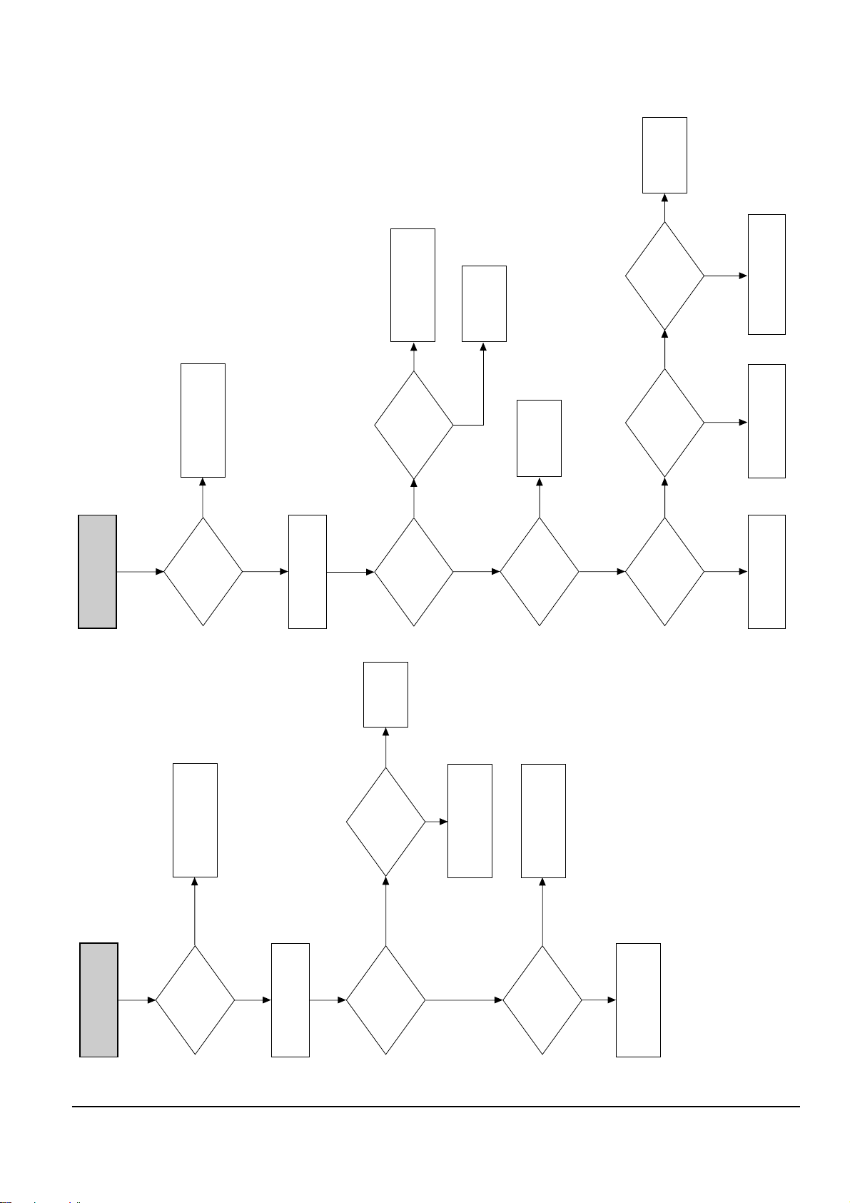
CHECK
AL 5.8V AT PIN
17 OF PT01
CHECK
AL 15 AT PIN
19 OF PT01
CHECK
AL 9V AT PIN
21 OF PT01
CHECK
AL 38V AT PIN
20 OF PT01
CHECK AND CHANGE
D33, C34, L33, C35
CHECK AND CHANGE
L31, D32, C32, L32, C33
CHECK AND CHANGE
L30, D31, C31
CHECK AND CHANGE
D30, C30
A
NO
NO
NO
NO
YES
YES
YES
Samsung Electronics 5-1
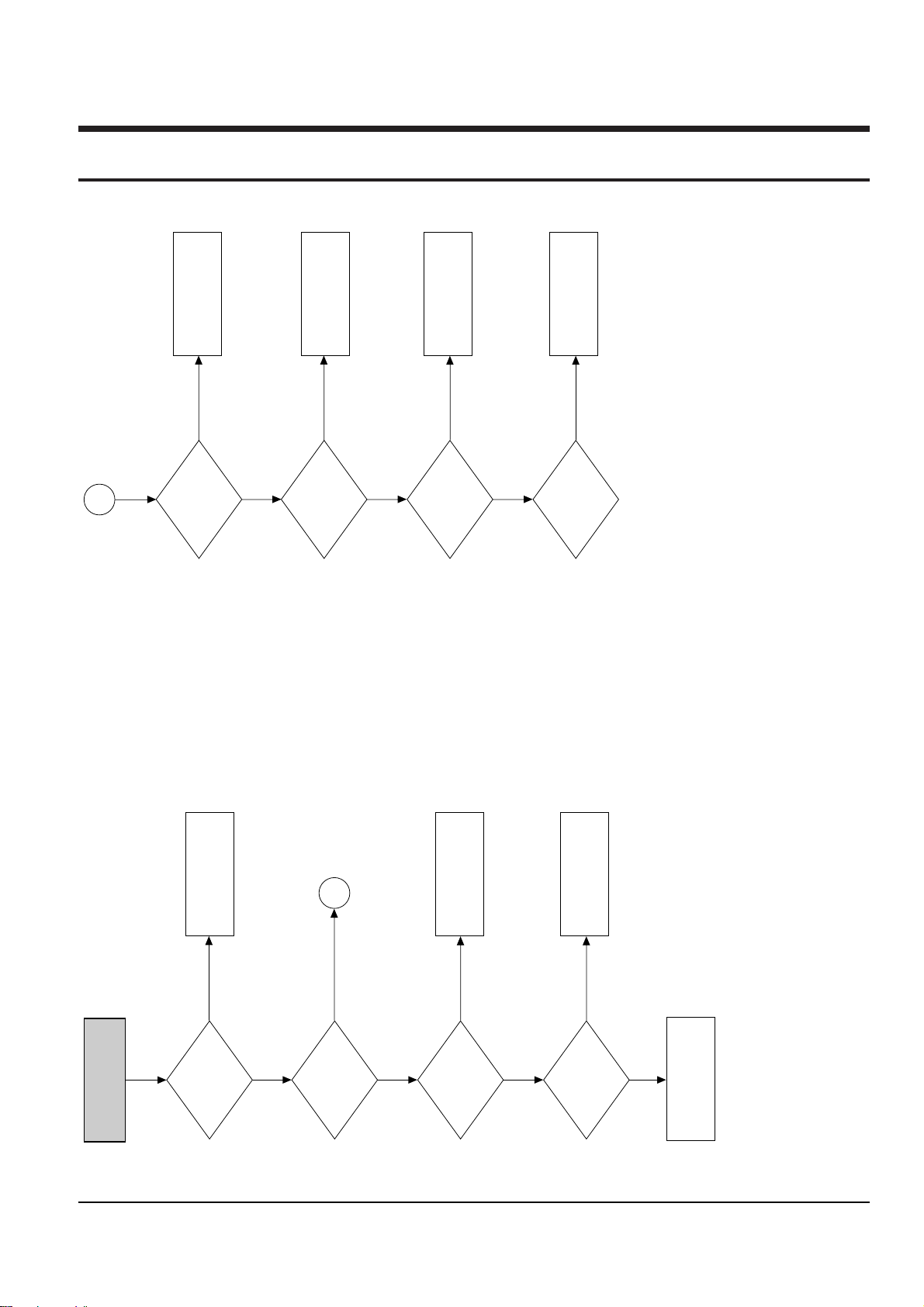
5. Troubleshooting
S.M.P.S.
INOPERATIVE
CHECK
AC CORD
CHECK
VOLTAGES AT PINS
2,6,8,10
OF PT01
CHECK
VOLTAGES
AT PIN 2 OF
PT1SD1
CHECK
VOLTAGES AT
IC01
CHECK R10
AND SECOND CIRCUITS
CHECK AND CHANGE
R10, R11, R12, R13, R14,
D10, R17
CHECK AND CHANGE
D01, D02, D03, D04, D05,
F01
CHANGE AC CORD
A
NO
NO
NO
YES
YES
NO
YES
YES
Alignment and Adjustment
5-2 Samsung Electronics
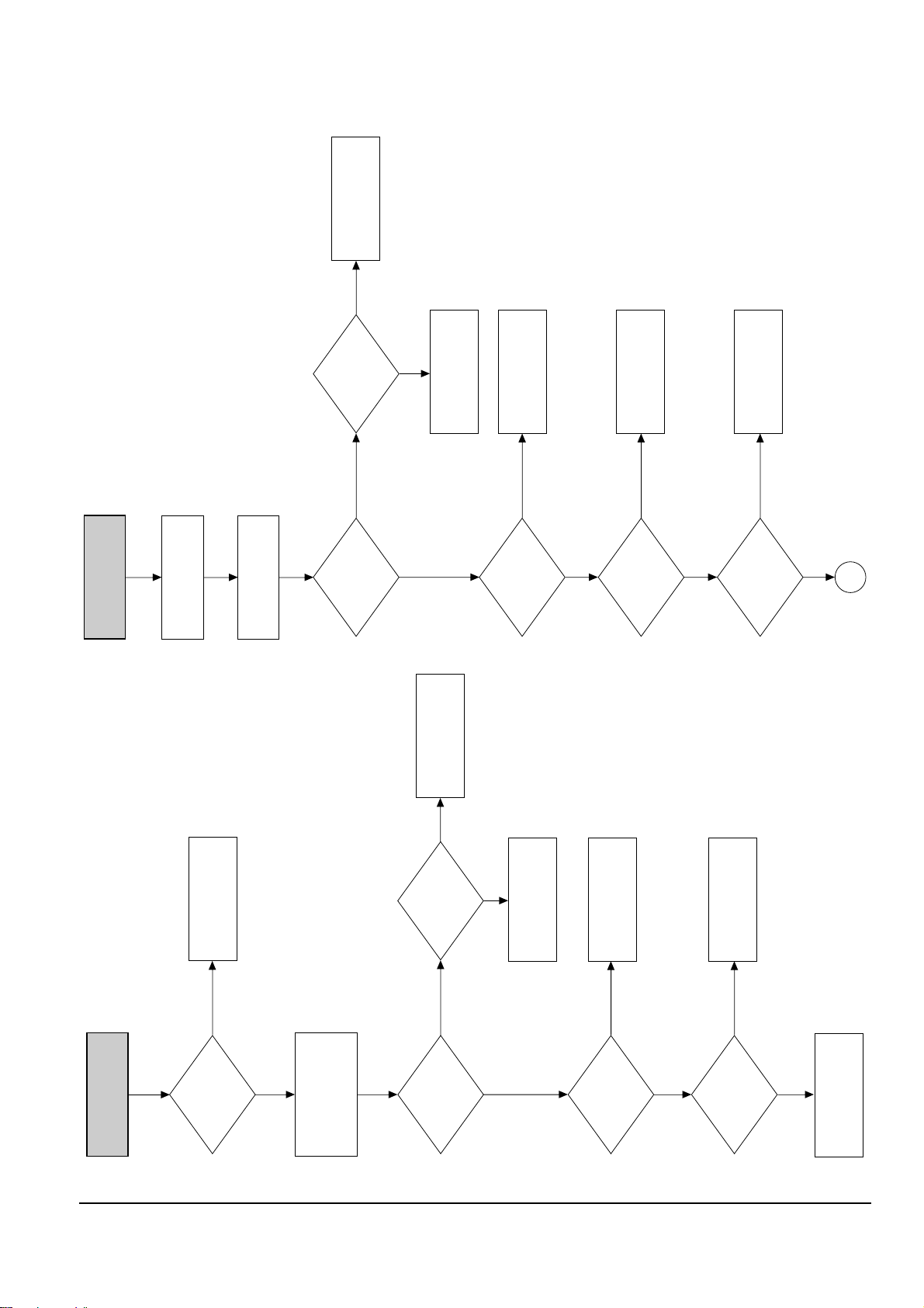
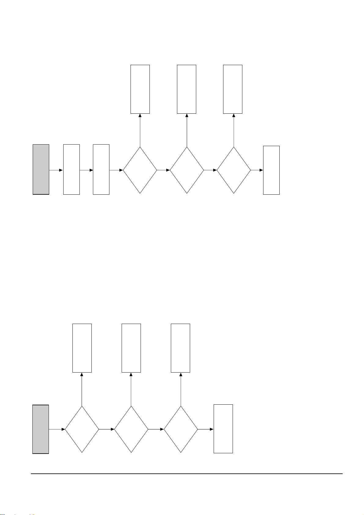
LOAD A TAPE AND
PRESS PLAY BUTTON
TURN VCR POWER ON
MECHANISM DOESN'T
OPERATE IN PLAY MODE
TAPE LOADING
OPERATION
(LOAD)
IC601-38:HIGH
IC601-39:LOW
(END SENSOR)
IC601-76
CYLINDER
ROTATION
NTSC : SW 30Hz
PAL : SW 25Hz
IC601-24
CYL FG.PG
IC601-96.97
SEE
(CYLINDER DOES
NOT ROTATE)
CHECK
START/END SENSOR
IC601
NO NO
NO
NO
LOW
YES
YES
HIGH
YES
YES
CHECK TAPE
CHECK IC602
B
PLAY MODE
INOPERATIVE
EE-VIDEO
INSERT THE CASETTE
TAPE RECORDED BY
ANOTHER VCR AND
PRESS PLAY BUTTON
PLAY
INDICATOR
IN THE DISPLAY
PRESS PLAY KEY
IN REMOTE
CONTROL
MECHANISM
OPERATION
SEE (PB VIDEO) AUDIO MISSING
IN PLAY MODE
SEE
(MECHANISM DOES NOT
OPERATE IN PLAY MODE)
CHECK TIMER
CHECK
IC601, XT602
SEE
VIDEO MISSING
IN EE MODE
NO
NO NO
YES
NO
PB-VIDEO
SEE
VIDEO MISSING
IN PLAY MODE
NO
YES
YES
YES
DOES NOT OPERATE
OR OPERATES
BUT STOP SOON
YES
Alignment and Adjustment
Samsung Electronics 5-3
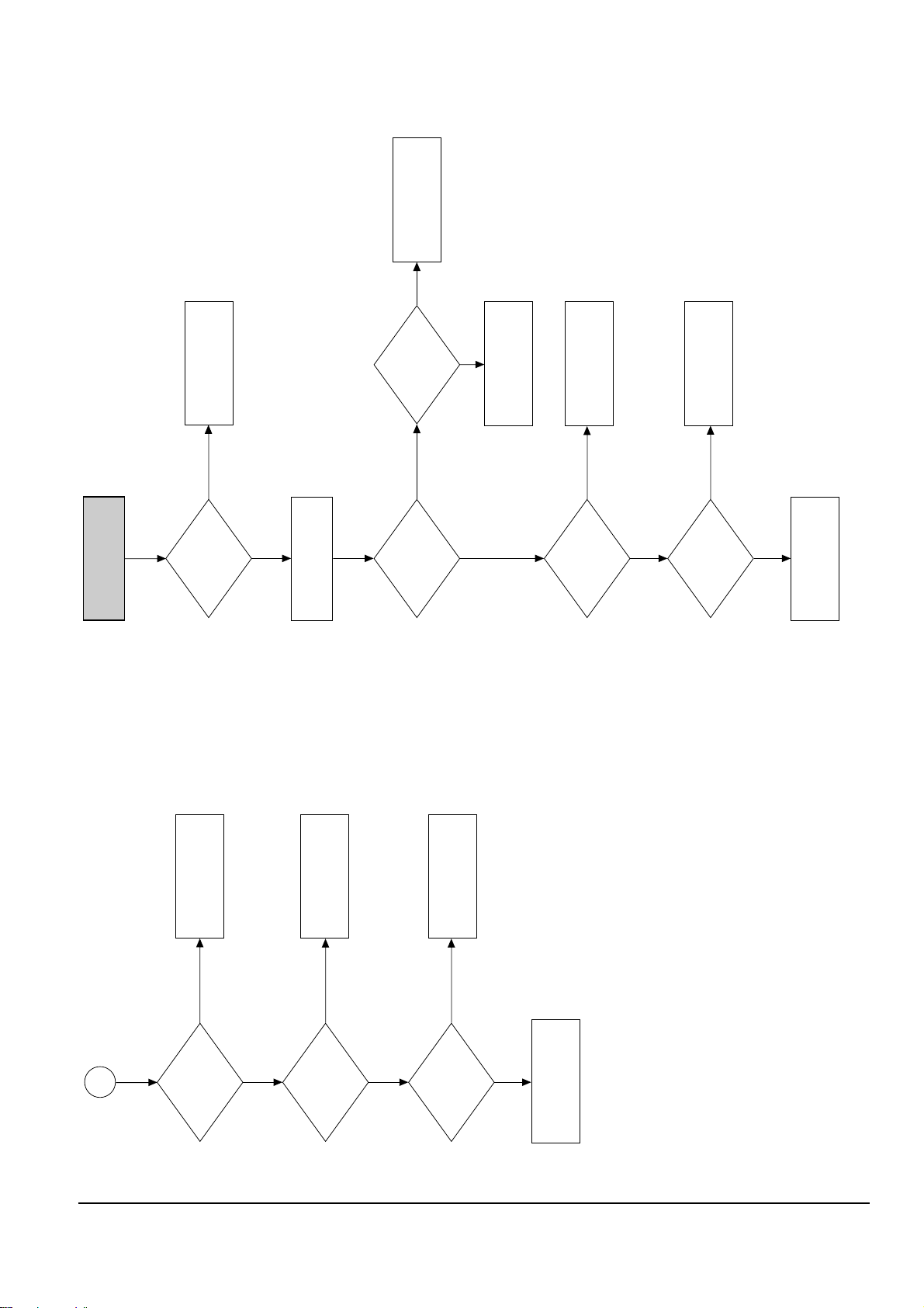
RECORD MODE
DOESN'T OPERATE
PLAY
OPERATION
LOAD VCR WITH A
BLANK TAPE AND
PRESS RECORD BUTTON
REC MODE
SAFETY TAB
D-REC A (H)
IC601-1
FULL ERASE (H)
IC601-68
SEE
(AUDIO MISSING IN
RECORD MODE)
CHANGE RS601
CHECK IC601
CHANGE TAPE
SEE
(PLAY MODE
DOESN'T OPERATE)
EJECT NO
YES
NO
REC-VIDEO
SEE
(VIDEO MISSING IN
RECORD MODE)
NO
YES
YES
YES
CAPSTAN
ROTATION
(S.T REEL)
IC601-98.99
PROG.SW STATE
IC601-63.64.65
CHANGE IC601
CHECK
LOADING MOTOR
MECHANISM OR SW601
TAKE UP REEL SENSOR
SUPPLY REEL SENSOR
(PT601.PT602)
SEE
(CAPSTAN DOES NOT
ROTATE)
B
NO
DC
STOP MODE
YES
PULSE
YES

Alignment and Adjustment
5-4 Samsung Electronics
LOAD A TAPE
REWIND DOESN'T
OPERATE
F.FWD
OPERATION
PRESS REWIND
BUTTON
REW
INDICATOR IN
THE DISPLAY
PRESS REW
KEY IN REMOTE
CONTROL
MECHANISM
STATE
IC601-93.98.99
CHECK
MECHANISM
CHECK TIMER
CHECK
IC601. XT602
SEE
(FAST FORWARD
DOESN'T WORK)
NO NO
YES
STOP
DOES CAPSTAN
MOTOR
ROTATE?
CHECK
IC601-25
(CM F/R)
SEE
(MECHANISM DOES NOT
OPERATE IN PLAY MODE)
NO
YES
F.FWD
YES
LOAD TAPE AND
PRESS F.FWD BUTTON
FAST FORWARD
DOESN'T OPERATE
F.FWD
INDICATOR IN
THE DISPLAY
PRESS FF
KEY IN REMOTE
CONTROL
MECHANISM
STATE
IC601-93.98.99
CHECK
MECHANISM
CHECK TIMER
CHANGE IC601, XT602
NO NO
YES
STOP
CAPSTAN MOTOR
ROTATION
SEE
(CAPSTAN DOES NOT
ROTATE)
SEE
(MECHANISM DOES NOT
OPERATE IN PLAY MODE)
STOP
YES
F.FWD
ROTATE

Alignment and Adjustment
Samsung Electronics 5-5
REV. SEARCH DOESN'T
OPERATE
PLAY
OPERATION
PRESS REWIND BUTTON
FOR REV. SEARCH
CHECK CAP F/R LINE
IS CAPSTAN
SPEED CHANGED?
SEARCH
OPERATION
FWD SEARCH
END
CHECK IC601
CHANGE DECK
CHANGE IC601
SEE
(PLAY
DOESN'T OPERATE)
NO
(PLAY MODE)
NO
YES
NO
CAP F/R
IC601-25
NO
(SEARCH MODE)
YES
NO
LOW
CHECK IC601
CHECK CAPSTAN
MOTOR
NOISE BAR
LOCKING
ADJUST
A/CE HEAD
NO
(CONTROL PULSE)
IC601-89
NO
YES
YES
FWD SEARCH DOESN'T
OPERATE
PLAY
OPERATION
PRESS F.FWD FOR
FORWARD SEARCH
CHECK IC601
CHECK CAPSTAN
MOTOR
IS CAPSTAN
SPEED CHANGED?
SEARCH
OPERATION
NOISE BAR
LOCKING
END
ADJUST
A/CE HEAD
CHANGE DECK
CHANGE IC601
SEE
(PLAY
DOESN'T OPERATE)
NO
NO
NO
YES
NO
(CONTROL PULSE)
IC601-89
NO
YES
YES
YES
YES

Alignment and Adjustment
5-6 Samsung Electronics
PLACE VCR IN STOP
MODE
VIDEO MISSING IN
EE MODE
TUNER MODE
OPERATION
NO
(EE INPUT
SIGNAL)
IC301-34
TUNER AND
DEMODU-
LATOR
APPLY VIDEO SIGNAL
(1Vp-p) TO VIDEO INPUT
JACK AND SET TO LINE MODE
NOTE: Location 43 series-I/O PCB
Location 3 series-Main PCB
CHECK C4362
CHECK IC4362,
R4362
CHECK IC4304
SEE PAGE 5-10
(DIGITAL BLOCK
NOT OPERATE)
CHECK AND
REPLACE
IC301
CHECK
VIDEO OUT
LINE
NO
(VIDEO OUT)
IC301-32
NO
NO
NO
NO
YES
YES
YES
YES
YES
YES
YES
YES
YES
NO NO
NO
VIDEO
IC4302 3~6
VIDEO
IC901-21
VIDEO
IC4305-7
VIDEO
IC4305-1
CHANGE
IC4305
CHECK
IC901
CHANGE
IC4302
VIDEO
IC4304-7
VIDEO
IC301-38
VIDEO
IC4301-7
NO
YES
TURN THE VCR
POWER ON AND
INSERT A TAPE
PRESS EJECT BUTTON
CASSETTE LOADING
MECHANISM
DOES NOT OPERATE
TAPE DETECTED
CST IN MODE
IC601-38:HIGH(5V)
IC601-39:LOW(0V)
CHANGE IC601
CHECK
START/END SENSOR
IC601
CHECK
LM B
+
LINE
CHANGE IC602
NO NO
YES
IC601-39:LOW(0V)
IC601-38:HIGH(5V)
IC602-5:HIGH(5V)
IC602-6:LOW(0V)
CHECK
CST LOADING
MECHANISM
YES
YES
NO
IC602-8:10V
YES
NO
YES
Alignment and Adjustment
Samsung Electronics 5-7
VIDEO MISSING IN
PLAY MODE
VIDEO EE MODE
OPERATION
PLACE THE VCR PLAY MODE
CHANGE IC301 CHECK IC4304
CHECK
VIDEO HEAD
CHECK
Q303-E
CHECK
IC601-24
CHECK VIDEO
OUT LINE
SEE PAGE 5-6
(VIDEO MISSING IN
EE MODE)
NO
YES
YES
NO
NO
YES
VIDEO FM
IC301-74
VIDEO
IC301-20
VIDEO
IC301-29
VIDEO
IC4304-7
VIDEO
IC4306-5,6
NO
H'D SW
IC301-11
NO
YES
YES
NO NO NO
CHECK IC4306
NOTE: Location 43 series-I/O PCB
Location 3, 6 series-Main PCB
VIDEO MISSING IN
RECORD MODE
PLACE THE VCR
RECORD MODE
VIDEO EE MODE
OPERATION
FM-VIDEO
IC301-12
FM-VIDEO
IC301-84.90
5V
IC301-30
CHECK VIDEO HEAD
CHECK IC601-68
CHANGE IC301
CHANGE
IC301
SEE PAGE 5-6
(VIDEO MISSING
IN EE MODE)
NO
NO YES
NO
YES
YES
YES

Alignment and Adjustment
5-8 Samsung Electronics
COLOR MISSING IN
PLAY MODE
FM-ENV
IC301-74
COLOR
IC301-59. 61
SW 25Hz
IC301-10
CHECK
XT3X1
XT302
XT3X2
CHANGE
IC301
CHECK IC601-29
CHANGE
XT3X1, XT3X2, XT302
CHECK Q308, C330, 328
SEE PAGE 5-7
(VIDEO MISSING IN
PLAY MODE)
NO
NO
NO
NO
NO
COLOR
IC301-71
NO
YES
YES
YES
YES
NOTE: XT3X1 - 4.43MHz (PAL/PAL-N/SECAM/MESECAM/NT4.43
XT302 - Always (3.579545MHz)
XT3X2 - 3.575611MHz (PAL-M)
COLOR MISSING IN
RECORD MODE
(VIDEO IN)
RECORD MODE
COLOR
IC301-72
COLOR
IC301-71
CHANGE IC301
CHANGE IC301
CHECK C304
CHANGE
XT3X1, XT3X2, XT302
CHECK
XT3X1
XT302
XT3X2
SEE PAGE 5-7
(VIDEO MISSING IN
RECORD MODE)
NO
NO
YES
NO
YES
NO
YES
YES
NOTE: XT3X1 - 4.43MHz (PAL/PAL-N/SECAM/MESECAM/NT4.43)
XT302 - Always (3.579545MHz)
XT3X2 - 3.575611MHz (PAL-M)
Alignment and Adjustment
Samsung Electronics 5-9
PLACE THE VCR IN STOP MODE
SELECT LINE MODE
WITHOUT INPUT SIGNAL
BLUE MISSING IN
STOP MODE
CHANGE
ICD6, LD2, CD64
CHECK
IC902-13 "L",
PIN15 5V
CHECK
ICD6-2 3.3V
CHECK
ICD2-30,
BLUE SIGNAL
CHECK ICD2
CHECK ICD3
NO
NO
NO
YES
YES
YES
CHECK
IC902 AL5V LINE
OSD PICTURE MISSING
XTAL IN
IC901-2
OSC IN
IC901-6
(STB, CLK, DATA)
IC901-9, 10, 11
CHANGE
IC901
CHECK IC601-6, 7, 8
CHECK L901, C903, C904
CHECK XT901, XT902
NO
NO
NO
YES
NO
YES
XTAL IN: 17.734476MHz (PAL/SECAM/PAL-N)
14.318MHz (NTSC/PAL-M/NT4.43)
OSC IN: 5~10MHz

Alignment and Adjustment
5-10 Samsung Electronics
ICD2-30
OUTPUT SIGNAL
ICD8-2
"H"
CHECK
ICD8, LD2, CD64, RD1
CHECK
ICD3-22
CHECK ICD2
APPLICATION CIRCUIT
CHECK ICD3
APPLICATION CIRCUIT
CHECK ICD3, RD9
ICD3-16
27MHz
ICD2-4
27MHz
ICD1-43
INPUT SIGNAL
ICD1-32
24, 6MHz
NO
NO
NO
NO
YES
YES
YES
NO
YES
YES
YES
CHECK
XD1, ICD1, CD12-CD14
NO
CHECK
RD24, CD4
C
YES
DIGITAL BLOCK NOT
OPERATE
THROUGH MODE
OPERATE
ICD8-2 "L"
ICD8-7
OUTPUT SIGNAL
ICD5-3, 4
OUTPUT SIGNAL
CHECK
CD60, CD61, CND2
I/O BLOCK
CHECK ICD5
APPLICATION CIRCUIT
CHECK ICD8
APPLICATION CIRCUIT
CHECK D3-22
C
YES
ICD8-1
INPUT SIGNAL
NO
NO
NO
NO
YES
NO
YES
YES
CHECK I/O BLOCK

Alignment and Adjustment
Samsung Electronics 5-11
MISSING AUDIO
IC501-16.37
AUDIO SIGNAL
IC501-27
AUDIO FM
IC501-26
AUDIO FM
IC501-11.40
AUDIO SIGNAL
CHECK
CYLINDER
CHECK
IC501
CHECK
IC501-15.38
C508, C517 AND CHANGE IC501
CHECK
R504 AND CHANGE IC501
CHECK
C519, C505
CHECK
AUDIO MISSING
IN EE MODE
AUDIO MISSING IN
REC MODE
MONO
HIFI
MONO
NONO
YES
NO
NO
YES
YES
YES
IC501-22.25:5V
CHECK
PC 5V LINE
NO
YES
PLACE VCR IN STOP
MODE
AUDIO MISSING IN
EE MODE
IC501-52,61
AUDIO SIGNAL
INPUT
INPUT SELECT
MODE
IC501-49, 63
AUDIO SIGNAL
INPUT
IC501-6, 44
AUDIO SIGNAL
INPUT
IC501-57
AUDIO SIGNAL
IC501-2, 48
AUDIO SIGNAL
INPUT
CHECK
R517, R518
R509, R510
CHECK
5V, 9V LINE
CHECK
IC601
CHECK
C524, C525
R514, R516
L1
L2
NO AV
NO
NO
CHECK TM401
YES
YES
YES
H
NO
L
YES
LINE OUT
TUNER
YES
YES
IC501-56.58
AUDIO SIGNAL
IC501-8
A. MUTE
IC501-5.45:1.9V
NO
CHECK
R521, R540
R522, R533
CHECK
R507, R508
R519, R520
CHECK
R501, R502,
R505, R506, MTS BLOCK
NO
YESNO
CHECK
C529
R406, R407
CHANGE
IC501
NO
TM401-2
AUDIO SIGNAL
D
D
D
YES
 Loading...