

Samsung SV-431F, SV-233BV, SV-234F, SV-231F, SV-231BV Service Manual
...
VIDEO CASSETTE RECORDER
SV-434F/431F/234F/231F
SV-233BV/231BV/230BV
SV-435XV/433XV/431XV/4313XV
SV-235XV/233XV/231XV/2315XV/2313XV
SV-230XV/230XDV/2300X
SV-435GV/430GV/235GV/230GV
SV-D2300G/D35G/D1111
SV-21
SERVICE
1. Precautions
2. Alignment and Adjustment
3. Exploded View and Parts List
4. Electrical Parts List
5. Schematic Diagrams
Manual
VIDEO CASSETTE RECORDER CONTENTS
For mechanical disassembly and adjustment, refer to the “Mechanical Manual” (DX-9R AC68-00001A).
SERVICE MANUAL
SV-434F/234F/233BV/230BV/435XV/235XV/230XV/435GV/235GV/D2300G/D35G/21
ELECTRONICS
© Samsung Electronics Co., Ltd. AUG. 2000
Printed in Korea
AC68-01030A
SV-434F/234F/435XV/235XV/233XV/435GV/235GV/D35G
SV-431F/231F/233BV/231BV/230BV/433XV/431XV/4313XV
SV-231XV/2315XV/2313XV/230XV/230XDV/430GV/230GV/21
SV-2300X/D2300G/D1111
REC STOP
PROG
EJECT
STANDBY/ON
REW F.F
PLAY
EJECT
STANDBY/ON
REW F.F
PLAY
PROG
REC STOP
STANDBY/ON
PLAY / STOP
REC
EJECT
IMPORTANT SERVICE GUIDE
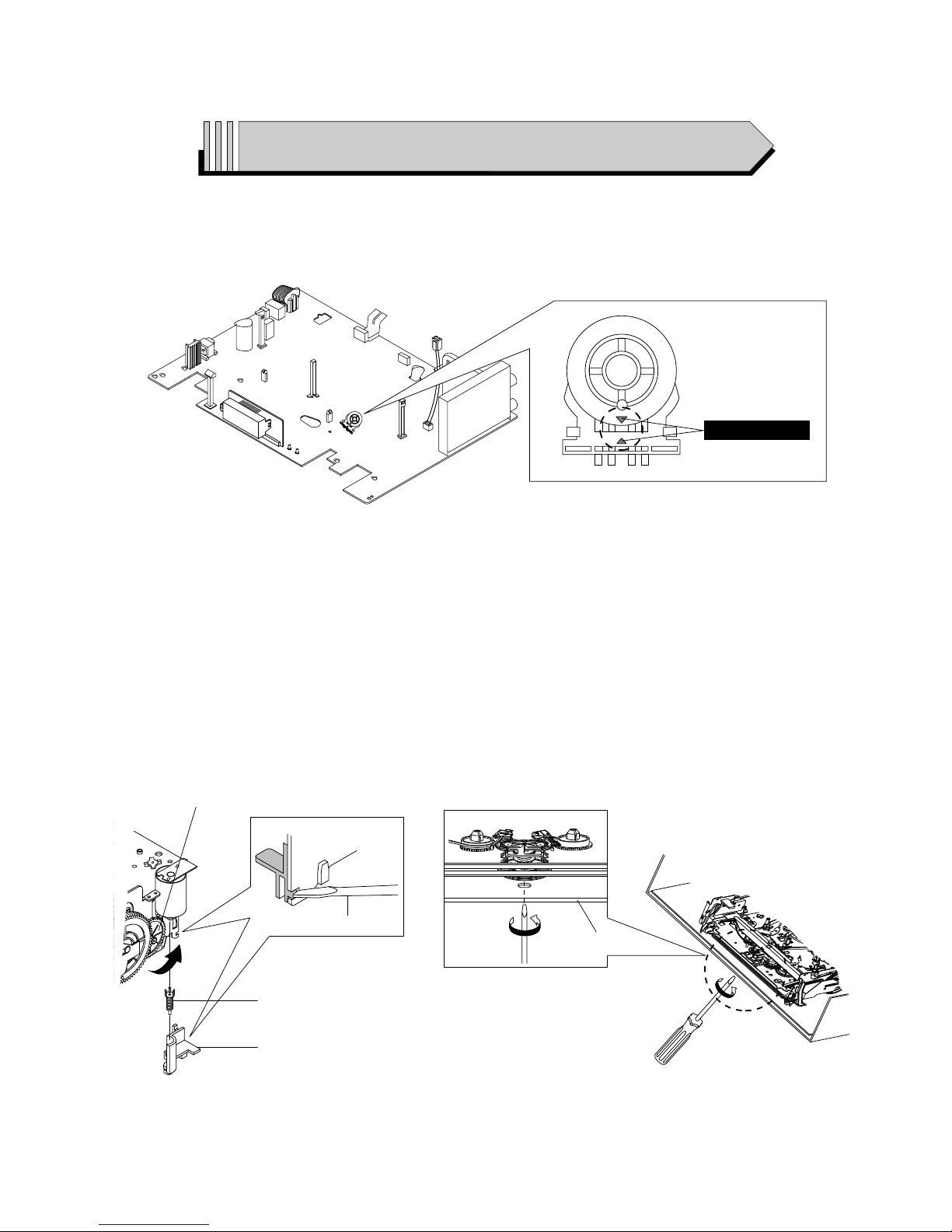
◆ MODE SWITCH (PROGRAM SWITCH) ASSEMBLY POINT
1) When installing the ass’y full deck on the Main PCB, be sure to align the assembly point of mode switch.
ASSEMBLY POINT
Fig. 1
◆ HOW TO EJECT THE CASSETTE TAPE
(If the unit does not operate on condition that tape is inserted into housing ass’y)
1) Remove the Holder Worm Œ and the gear worm ´. (See Fig. 2)
2) Turn the Gear Worm Wheel ˇ counterclockwise in the direction of arrow with screw driver. (See Fig. 2)
3) When Slider S, T are approached in the position of unloading, rotate holder Clutch counterclockwise after inserting screw driver in the
hole of frame’s bottom in order to wind the unwounded tape. (Refer to Fig. 3)
(If you rotate Gear Worm Wheel continuously when tape is in state of unwinding, you may cause a tape contamination by grease and
tape damage. Be sure to wind the unwounded tape in the state of set horizontally.)
4) Rotate Gear Worm Wheel ˇ counterclockwise using screw driver again up to the state of eject mode and then pick out the tape.
(Refer to Fig. 2)
Fig. 2 Fig. 3
ΠHOLDER WORM
´ GEAR WORM
SCREW DRIVER
ˇ GEAR WORM WHEEL
FRAME
Samsung Electronics 1-1
1. Precautions
1. Be sure that all of the built-in protective devices are
replaced. Restore any missing protective shields.
2. When reinstalling the chassis and its assemblies, be
sure to restore all protective devices, including :
control knobs and compartment covers.
3. Make sure that there are no cabinet openings
through which people--particularly children
--might insert fingers and contact dangerous
voltages. Such openings include the spacing
between the picture tube and the cabinet mask,
excessively wide cabinet ventilation slots, and
improperly fitted back covers.
If the measured resistance is less than 1.0 megohm
or greater than 5.2 megohms, an abnormality exists
that must be corrected before the unit is returned
to the customer.
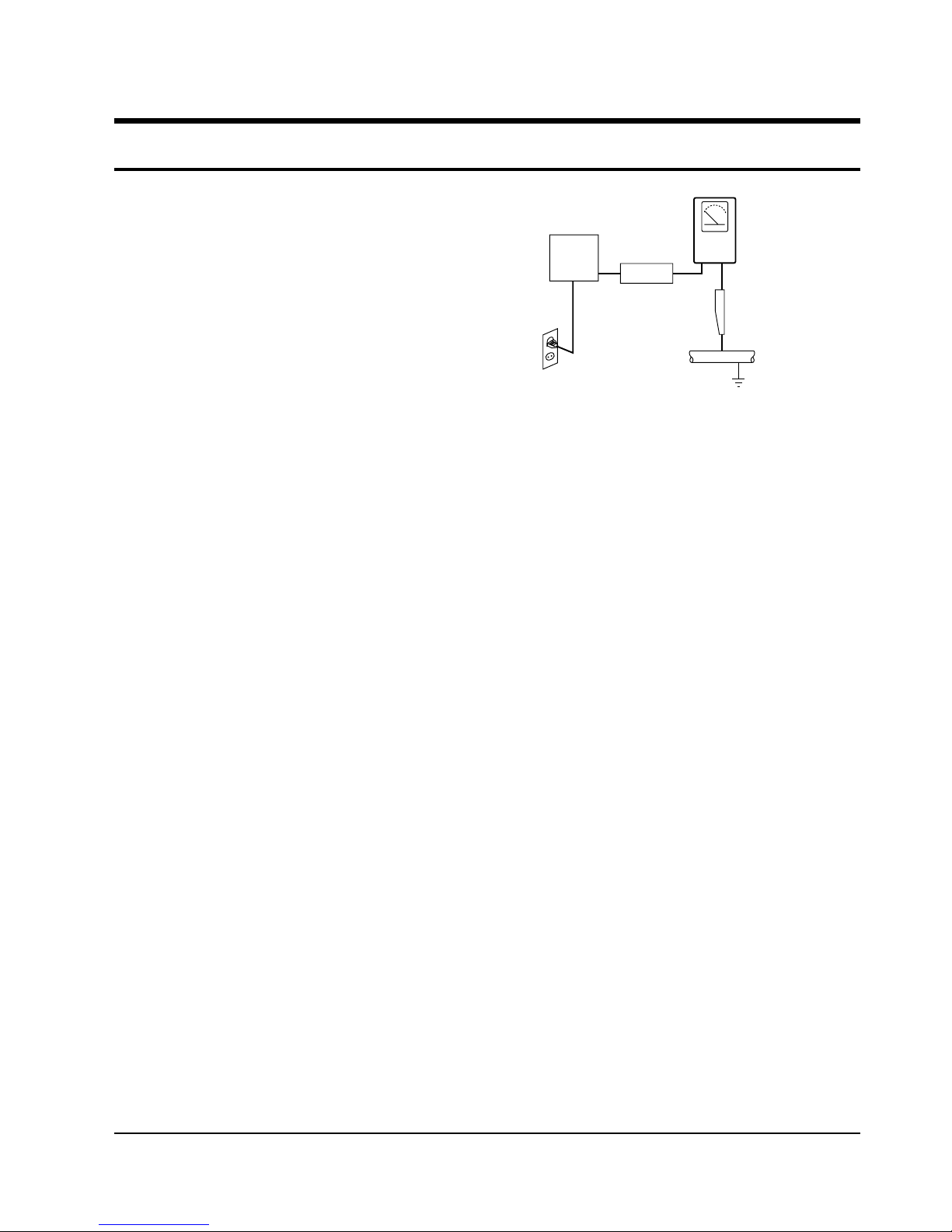
4. Leakage Current Hot Check (See Fig. 1-1) :
Warning : Do not use an isolation transformer
during this test. Use a leakage current tester or a
metering system that complies with American
National Standards Institute (ANSI C101.1,
Leakage Current for Appliances), and Underwriters
Laboratories (UL Publication UL1410, 59.7).
5. With the unit completely reassembled, plug the AC
line cord directly the power outlet. With the unit’s
AC switch first in the ON position and then OFF,
measure the current between a known earth
ground (metal water pipe, conduit, etc.) and all
exposed metal parts, including : antennas, handle
brackets, metal cabinets, screwheads and control
shafts. The current measured should not exceed
0.5 milliamp. Reverse the power-plug prongs in the
AC outlet and repeat the test.
6. X-ray Limits :
The picture tube is designed to prohibit X-ray
emissions. To ensure continued X-ray protection,
replace the picture tube only with one that is the
same type as the original.
Fig. 1-1 AC Leakage Test
7. Antenna Cold Check :
With the unit’s AC plug disconnected from the
AC source, connect an electrical jumper across the
two AC prongs. Connect one lead of the ohmmeter
to an AC prong.
Connect the other lead to the coaxial connector.
8. High Voltage Limit :
High voltage must be measured each time
servicing is done on the B+, horizontal deflection
or high voltage circuits.
Heed the high voltage limits. These include the
X-ray protection Specifications Label, and the
Product Safety and X-ray Warning Note on the
service data schematic.
9. Some semiconductor (“solid state”) devices are
easily damaged by static electricity.
Such components are called Electrostatically
Sensitive Devices (ESDs); examples include
integrated circuits and some field-effect transistors.
The following techniques will reduce the
occurrence of component damage caused by static
electricity.
10. Immediately before handling any semiconductor
components or assemblies, drain the electrostatic
charge from your body by touching a known
earth ground. Alternatively, wear a discharging
Wrist-strap device. (Be sure to remove it prior to
applying power--this is an electric shock
precaution.)
DEVICE
UNDER
TEST
(READING SHOULD
NOT BE ABOVE
0.5mA)
LEAKAGE
CURRENT
TESTER
EARTH
GROUND
TEST ALL
EXPOSED METER
SURFACES
ALSO TEST WITH
PLUG REVERSED
(USING AC ADAPTER
PLUG AS REQUIRED)
2-WIRE CORD

Precautions
1-2 Samsung Electronics
11. High voltage is maintained within specified limits
by close-tolerance, safety-related components and
adjustments. If the high voltage exceeds the
specified limits, check each of the special
components.
12. Design Alteration Warning :
Never alter or add to the mechanical or electrical
design of this unit. Example : Do not add
auxiliary audio or video connectors.
Such alterations might create a safety hazard.
Also, any design changes or additions will void
the manufacturer’s warranty.
13. Hot Chassis Warning :
Some TV receiver chassis are electrically
connected directly to one conductor of the AC
power cord. If an isolation transformer is not
used, these units may be safely serviced only if
the AC power plug is inserted so that the chassis
is connected to the ground side of the AC source.
To confirm that the AC power plug is inserted
correctly, do the following : Using an AC
voltmeter, measure the voltage between the
chassis and a known earth ground. If the reading
is greater than 1.0V, remove the AC power plug,
reverse its polarity and reinsert. Re-measure the
voltage between the chassis and ground.
14. Some TV chassis are designed to operate with 85
volts AC between chassis and ground, regardless
of the AC plug polarity. These units can be safely
serviced only if an isolation transformer inserted
between the receiver and the power source.
15. Never defeat any of the B+ voltage interlocks.
Do not apply AC power to the unit (or any of its
assemblies) unless all solid-state heat sinks are
correctly installed.
16. Always connect a test instrument’s ground lead to
the instrument chassis ground before connecting
the positive lead; always remove the instrument’s
ground lead last.
17. Observe the original lead dress, especially near
the following areas : Antenna wiring, sharp
edges, and especially the AC and high voltage
power supplies. Always inspect for pinched, outof-place, or frayed wiring. Do not change the
spacing between components and the printed
circuit board. Check the AC power cord for
damage. Make sure that leads and components
do not touch thermally hot parts.
18. Picture Tube Implosion Warning :
The picture tube in this receiver employs
“integral implosion” protection. To ensure
continued implosion protection, make sure that
the replacement picture tube is the same as the
original.
19. Do not remove, install or handle the picture tube
without first putting on shatterproof goggles
equipped with side shields. Never handle the
picture tube by its neck. Some “in-line” picture
tubes are equipped with a permanently attached
deflection yoke; do not try to remove such
“permanently attached” yokes from the picture
tube.
20. Product Safety Notice :
Some electrical and mechanical parts have special
safety-related characteristics which might not be
obvious from visual inspection. These safety
features and the protection they give might be
lost if the replacement component differs from the
original--even if the replacement is rated for
higher voltage, wattage, etc.
Components that are critical for safety are
indicated in the circuit diagram by shading,
( or ).
Use replacement components that have the same
ratings, especially for flame resistance and
dielectric strength specifications. Areplacement
part that does not have the same safety
characteristics as the original might create shock,
fire or other hazards.
Samsung Electronics
2-1
2. Alignment and Adjustment
2-1 Reference
1) X-Point (Tracking center) adjustment, “Head switching adjustment” and “NVRAM option setting” can be adjusted with remote control.
2) When replacing the Micom (IC601) and NVRAM (IC605 ; EEPROM) be sure to adjust the “Head switching adjustment” and
“NVRAM option setting”.
3) When replacing the cylinder ass’y, be sure to adjust the “X-Point” and “Head switching adjustment”.
4) Among Samsung VCR remote control used for adjustment as a accessory, only the remote control that has figures buttons (0 ~ 9) is
available for all adjustment regardless of chassis.
5) How to adjustment.
- Intermittently short-circuit the two test point on Main PCB with pincers to set the adjustment mode.
- If the corresponding adjustment button is pressed, the adjustment is performed automatically.
- If the adjustment is completed, be sure to turn the power off.
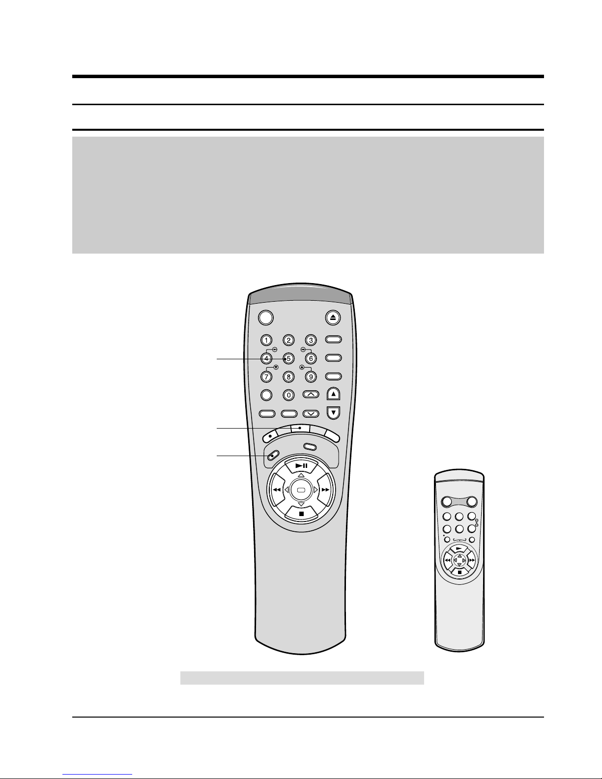
2-1-1 Location of adjustment button of remote control
Fig. 2-1
Q-PRO
IPC
DISPLAY
SHUTTLE
V-LOCK
CLR/RST F.ADV
INPUT INDEX
TRK PROG
R
E
C
M
E
N
U
A
U
D
I
O
S
P
E
E
D
T
V
/
V
C
R
REPEAT
OK
<This type of remote control can adjust.>
<This type of remote control can not adjust.>
Remote Control for adjustment is not supplied as a Service Jig.
R
E
P
E
A
T
POWER DISPLAY
CNT.RESET SPEED
IIP/S IPC
TRK
REC MENU
Head Switching Adjustment
("SPEED" Button)
NVRAM Option Setting
("MENU" Button)
X-Point (Tracking Center) Adjustment
("5" Button)
STANDBY/ON EJECT
2-2
Samsung Electronics
Alignment and Adjustment
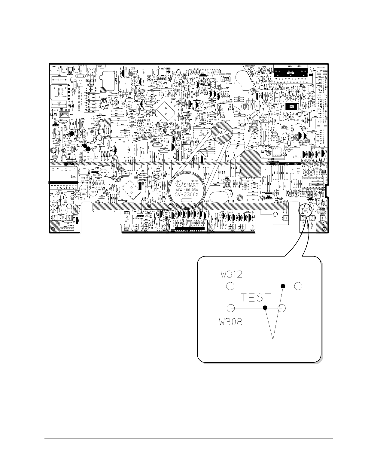
2-1-2 Test point location for adjustment mode setting
Fig. 2-2 Main PCB (Top View)
Short-circuit for faw seconds and release.
(Just one time)
Alignment and Adjustment
Samsung Electronics
2-3
2-2 Mechanical Adjustment
Note : Refer to the Mechanical Manual “DX-9R (AC68-00001A)” for the adjustment and confirmation of
ass’y full deck.
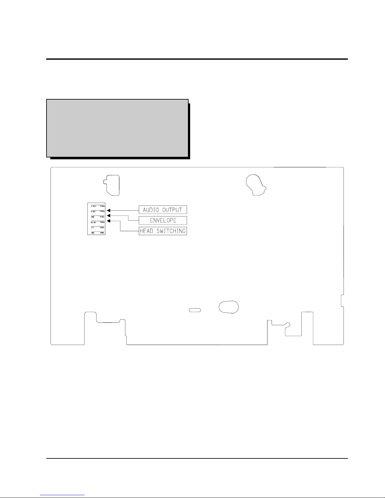
2-2-1 The number and position of test point
Test point : TP601 (Control Pulse)
TP602 (H’D S/W -Trigger)
TP301 (Envelope)
TP302 (Audio output)
TP303 (Video output)
Fig. 2-3 Location of Test point (Main PCB-Top View)
2-2-2 ACE Head Position (X-Point) Adjustment
(See the 2-2-1(d) ACE Head Position (X-Point) Adjustment
on page 2-2 of the Mechanical Manual)
1) Playback the alignment tape (Color bar).
2) Intermittently short-circuit the two test point
button on Main PCB to set the adjustment mode.
(See Fig. 2-2)
3) Press the “5” button of remote control then
adjustment is operated automatically. (See Fig. 2-1)
4) Connect the CH-1 probe to TP301 (Envelope) the
CH-2 probe to TP602 (H’D switching pulse) and
then trigger to CH-1.
5) Insert the (-) driver into the X-Point adjustment
hole and adjust it so that envelope waveform is
maximum.
6) Turn the Power off.
2-4
Samsung Electronics
Alignment and Adjustment
2-3 Head Switching Point Adjustment
1) Playback the alignment tape.
2) Intermittently short-circuit the two test point button on Main PCB to set the adjustment mode. (See Fig. 2-2)
3) Press the “SPEED” button of remote control then adjustment is operated automatically. (See Fig. 2-1)
4) Turn the Power off.
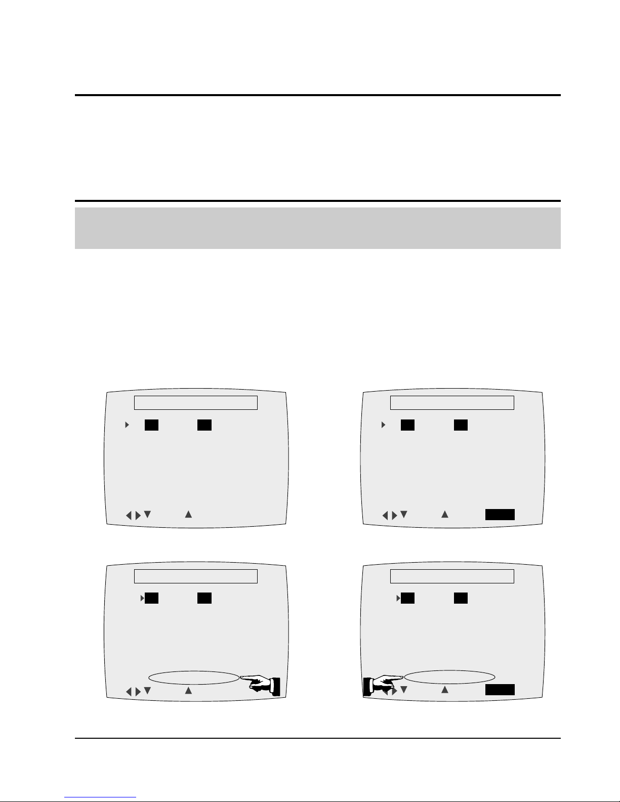
2-4 NVRAM Option Setting
1) Intermittently short-circuit the two test point button on Main PCB to set the adjustment mode. (See Fig. 2-2)
2) Press the “MENU” button on the remote control about 5 seconds then option setting display is appeared.
(See Fig. 2-4 and 2-5)
3) Select the option number (See Table 2-1 ; Page 2-5) of corresponding model with “FF” and “REW” button on
the remote control.
4) If selecting the option number is completed, press the “PLAY” button of remote control.
(If “PLAY” button is pressed, the selected number is changes reversed color. ; See Fig. 2-4 and 2-5)
5) Press the “OK (VCR)”, “MENU (VCP)” button of remote control again to store the option number.
(“PLEASE WAIT” is displayed for a second as shown Fig. 2-6, 2-7 and this setting is completed.)
6) Turn the Power off.
1) NVRAM Option is adjusted at production line basically.
2) In case Micom (IC601) and NVRAM (IC605 ; EEPROM) is replaced, be sure to set the corresponding option number of the reqaired
model. (If the option is not set, the unit is not operated.)
01 02 03 04 05 06 07 08
09 10 11 12 13 14 15 16
17 18 19 20 21 22 23 24
25 26 27 28 29 30 31 32
33 34 35 36 37 38 39 40
41 42 43 44 45 46 47 48
49 50 51 52 53 54 55 56
**
OPTION DIODE
**
CNG : SAVE : OK
Fig. 2-4 (VCR)
01 02 03 04 05 06 07 08
09 10 11 12 13 14 15 16
17 18 19 20 21 22 23 24
25 26 27 28 29 30 31 32
33 34 35 36 37 38 39 40
41 42 43 44 45 46 47 48
49 50 51 52 53 54 55 56
**
OPTION DIODE
**
CNG : SAVE : MENU
Fig. 2-5 (VCP)
01 02 03 04 05 06 07 08
09 10 11 12 13 14 15 16
17 18 19 20 21 22 23 24
25 26 27 28 29 30 31 32
33 34 35 36 37 38 39 40
41 42 43 44 45 46 47 48
49 50 51 52 53 54 55 56
**
OPTION DIODE
**
CNG : SAVE : OK
PLEASE WAIT
Fig. 2-6 (VCR)
01 02 03 04 05 06 07 08
09 10 11 12 13 14 15 16
17 18 19 20 21 22 23 24
25 26 27 28 29 30 31 32
33 34 35 36 37 38 39 40
41 42 43 44 45 46 47 48
49 50 51 52 53 54 55 56
**
OPTION DIODE
**
CNG : SAVE : MENU
PLEASE WAIT
Fig. 2-7 (VCP)
Alignment and Adjustment
Samsung Electronics
2-5
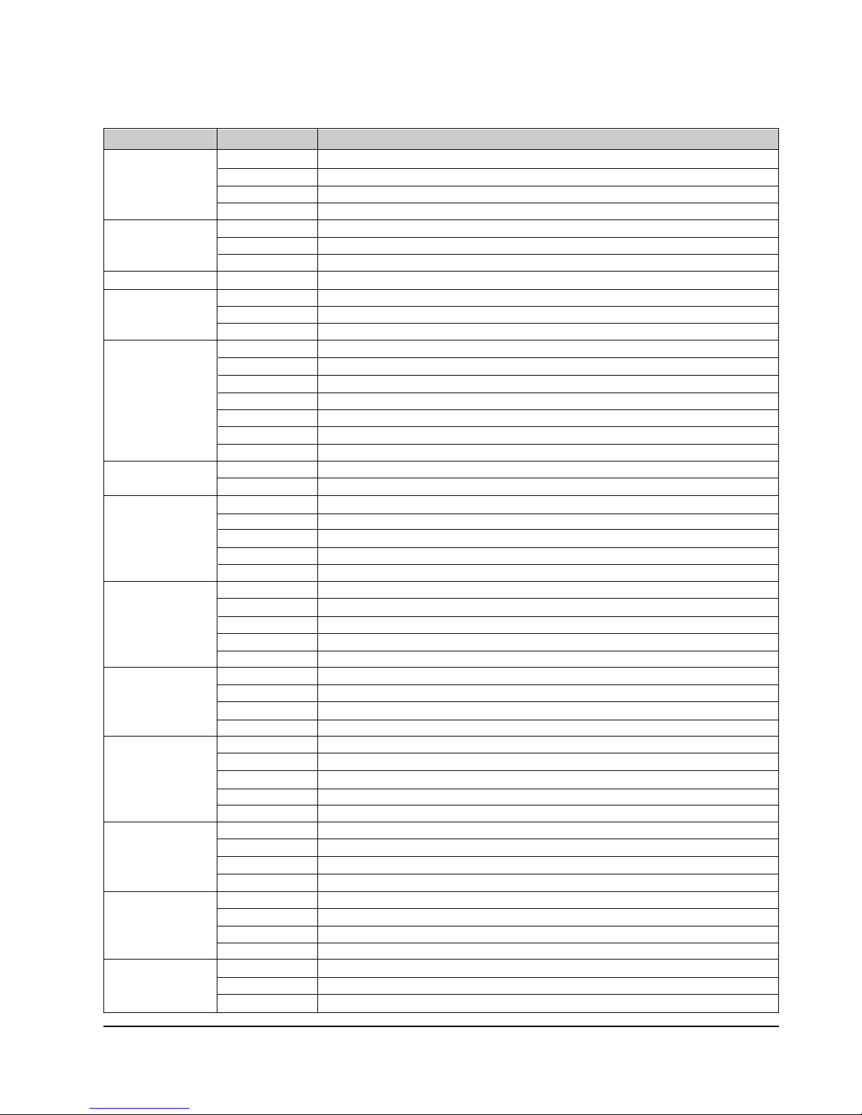
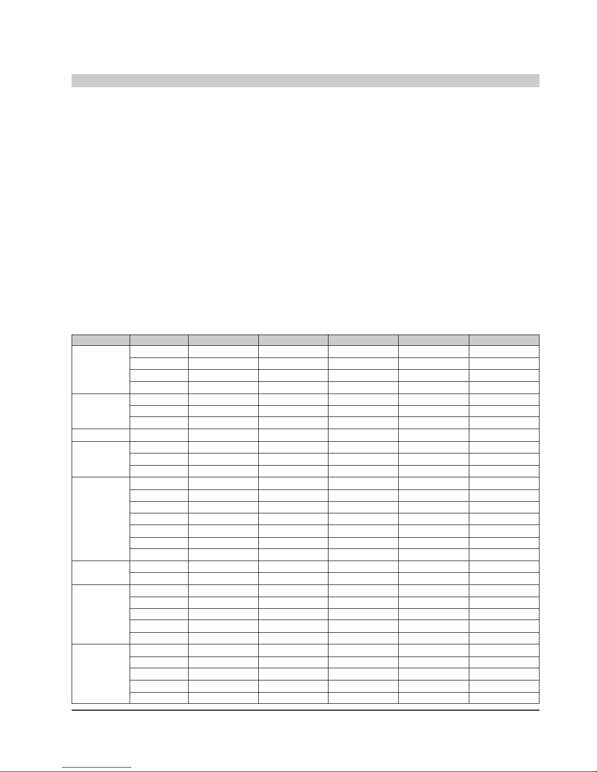
<Table 2-1>
COUNTRY MODELS OPTION NUMBER
France SV-434F 2, 5, 6, 7, 8, 12, 18, 19, 22, 23, 24, 26, 29, 35, 37, 46, 50, 53, 54, 55
SV-431F 5, 7, 8 ,12, 18, 19, 22, 23, 24, 26, 29, 35, 38, 46, 50, 53, 54, 55
SV-234F 2, 5, 6, 7, 18, 19, 22, 23, 24, 26, 29, 35, 37, 46, 50, 53, 54, 55
SV-231F 5, 7, 18, 19, 22, 23, 24, 26, 29, 35, 38, 46, 50, 53, 54, 55
U.K. SV-233BV 3, 7, 8, 10, 22, 24, 27, 35, 38, 46, 50, 54, 55
SV-231BV 3, 8, 10, 22, 27, 35, 38, 46, 50, 54
SV-230BV 8, 10, 22, 27, 35, 38, 46, 50, 54
Germany SV-435XV 2, 5, 6, 7, 8, 12, 18, 22, 23, 24, 30, 35, 37, 46, 50, 53, 54, 55
Spain SV-431XV 5, 7, 8, 12, 18, 22, 23, 24, 30, 35, 38, 46, 50, 53, 54, 55
SV-235XV 5, 6, 7, 18, 22, 23, 24, 30, 35, 37, 46, 50, 53, 54, 55
SV-231XV 5, 7, 18, 22, 23, 24, 30, 35, 38, 46, 50, 53, 54, 55
Italy SV-435XV 2, 5, 6, 7, 8, 12, 18, 22, 23, 24, 30, 35, 37, 46, 50, 53, 54, 55
SV-431XV 5, 7, 8, 12, 18, 22, 23, 24, 30, 35, 38, 46, 50, 53, 54, 55
SV-4313XV 5, 7, 8, 12, 18, 22, 23, 24, 30, 35, 38, 46, 50, 53, 54, 55
SV-235XV 5, 6, 7, 18, 22, 23, 24, 30, 35, 37, 46, 50, 53, 54, 55
SV-2315XV 5, 7, 18, 22, 23, 24, 30, 35, 38, 46, 50, 53, 54, 55
SV-2313XV 5, 7, 18, 22, 23, 24, 30, 35, 38, 46, 50, 53, 54, 55
SV-231XV 5, 7, 18, 22, 23, 24, 30, 35, 38, 46, 50, 53, 54, 55
Portugal SV-431XV 5, 7, 8, 12, 18, 22, 23, 24, 30, 35, 38, 46, 50, 53, 54, 55
SV-231XV 5, 7, 18, 22, 23, 24, 30, 35, 38, 46, 50, 53, 54, 55
Denmark SV-435XV 2, 5, 6, 7, 8, 12, 18, 22, 23, 24, 30, 35, 37, 46, 50, 53, 54, 55
SV-431XV 5, 7, 8, 12, 18, 22, 23, 24, 30, 35, 38, 46, 50, 53, 54, 55
SV-235XV 5, 6, 7, 18, 22, 23, 24, 30, 35, 37, 46, 50, 53, 54, 55
SV-230XV 7, 18, 22, 24, 30, 35, 38, 46, 50, 54, 55
SV-2300X 7, 18, 22, 24, 30, 34, 39, 46, 50, 54, 55
Sweden/Finland SV-435XV 2, 5, 6, 7, 8, 12, 18, 22, 23, 24, 30, 35, 37, 46, 50, 53, 54, 55
SV-431XV 5, 7, 8, 12, 18, 22, 23, 24, 30, 35, 38, 46, 50, 53, 54, 55
SV-235XV 5, 6, 7, 18, 22, 23, 24, 30, 35, 37, 46, 50, 53, 54, 55
SV-230XV 7, 18, 22, 24, 30, 35, 38, 46, 50, 54, 55
SV-2300X 7, 18, 22, 24, 30, 34, 39, 46, 50, 54, 55
Norway SV-435XV 2, 5, 6, 7, 8, 12, 18, 22, 23, 24, 30, 35, 37, 46, 50, 53, 54, 55
SV-431XV 5, 7, 8, 12, 18, 22, 23, 24, 30, 35, 38, 46, 50, 53, 54, 55
SV-235XV 5, 6, 7, 18, 22, 23, 24, 30, 35, 37, 46, 50, 53, 54, 55
SV-230XV 7, 18, 22, 24, 30, 35, 38, 46, 50, 54, 55
Netherland SV-435XV 2, 5, 6, 7, 8, 12, 18, 22, 23, 24, 30, 35, 37, 46, 50, 53, 54, 55
SV-431XV 5, 7, 8, 12, 18, 22, 23, 24, 30, 35, 38, 46, 50, 53, 54, 55
SV-235XV 5, 6, 7, 18, 22, 23, 24, 30, 35, 37, 46, 50, 53, 54, 55
SV-230XV 7, 18, 22, 24, 30, 35, 38, 46, 50, 54, 55
SV-230XDV 7, 18, 22, 24, 30, 35, 38, 46, 50, 54, 55
Switzerland SV-435XV 2, 5, 6, 7, 8, 12, 18, 22, 23, 24, 30, 35, 37, 46, 50, 53, 54, 55
SV-433XV 2, 5, 7, 8, 12, 18, 22, 23, 24, 30, 35, 38, 46, 50, 53, 54, 55
SV-233XV 2, 7, 18, 22, 24, 30, 35, 37, 46, 50, 54, 55
SV-230XV 7, 18, 22, 24, 30, 35, 38, 46, 50, 54, 55
Austria SV-435XV 2, 5, 6, 7, 8, 12, 18, 22, 23, 24, 30, 35, 37, 46, 50, 53, 54, 55
SV-433XV 2, 5, 7, 8, 12, 18, 22, 23, 24, 30, 35, 38, 46, 50, 53, 54, 55
SV-233XV 2, 7, 18, 22, 24, 30, 35, 37, 46, 50, 54, 55
SV-230XV 7, 18, 22, 24, 30, 35, 38, 46, 50, 54, 55
Greece SV-435XV 2, 5, 6, 7, 8, 12, 18, 22, 23, 30, 35, 37, 46, 50, 53, 54
SV-431XV 5, 8, 12, 18, 22, 23, 30, 35, 38, 46, 50, 53, 54
SV-230XV 18, 22, 30, 35, 38, 46, 50, 54
2-6
Samsung Electronics
Alignment and Adjustment
MEMO
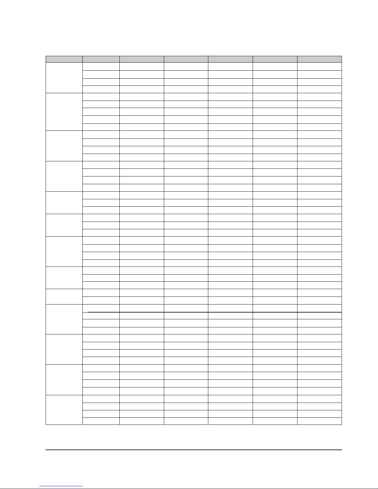
COUNTRY MODELS OPTION NUMBER
Cyprus SV-435XV 2, 5, 6, 7, 8, 12, 18, 22, 23, 30, 35, 37, 46, 50, 53, 54
SV-431XV 5, 8, 12, 18, 22, 23, 30, 35, 38, 46, 50, 53, 54
SV-230XV 18, 22, 30, 35, 38, 46, 50, 54
Croatia SV-435XV 2, 5, 6, 7, 8, 12, 18, 22, 23, 30, 35, 37, 46, 50, 53, 54
SV-431XV 5, 8, 12, 18, 22, 23, 30, 35, 38, 46, 50, 53, 54
SV-235XV 2, 5, 6, 7, 18, 22, 23, 30, 35, 37, 46, 50, 53, 54
SV-230XV 18, 22, 30, 35, 38, 46, 50, 54
Slovenia SV-435XV 2, 5, 6, 7, 8, 12, 18, 22, 23, 30, 35, 37, 46, 50, 53, 54
SV-431XV 5, 8, 12, 18, 22, 23, 30, 35, 38, 46, 50, 53, 54
SV-233XV 2, 7, 18, 22, 30, 35, 37, 46, 50, 54
Yugo SV-435XV 2, 5, 6, 7, 8, 12, 18, 22, 23, 30, 35, 37, 46, 50, 53, 54
SV-233XV 2, 7, 18, 22, 30, 35, 37, 46, 50, 54
Hungary SV-435GV 2, 5, 6, 7, 8, 11, 12, 18, 22, 23, 25, 30, 35, 37, 41, 46, 50, 53, 54
SV-430GV 8, 11, 12, 18, 22, 25, 30, 35, 38, 46, 50, 54
SV-235GV 2, 5, 6, 7, 11, 18, 22, 23, 25, 30, 35, 37, 46, 50, 53, 54
SV-230GV 11, 18, 22, 25, 30, 35, 38, 46, 50, 53, 54
Romania SV-435GV 2, 5, 6, 7, 8, 11, 12, 18, 22, 23, 25, 30, 35, 37, 41, 46, 50, 53, 54
SV-430GV 8, 11, 12, 18, 22, 25, 30, 35, 38, 46, 50, 54
SV-235GV 2, 5, 6, 7, 11, 18, 22, 23, 25, 30, 35, 37, 46, 50, 53, 54
SV-230GV 11, 18, 22, 25, 30, 35, 38, 46, 50, 53, 54
Czech SV-435GV 2, 5, 6, 7, 8, 11, 12, 18, 22, 23, 25, 30, 35, 37, 41, 46, 50, 53, 54
SV-430GV 8, 11, 12, 18, 22, 25, 30, 35, 38, 46, 50, 54
SV-235GV 2, 5, 6, 7, 11, 18, 22, 23, 25, 30, 35, 37, 46, 50, 53, 54
SV-230GV 11, 18, 22, 25, 30, 35, 38, 46, 50, 53, 54
Bulgaria SV-435GV 2, 5, 6, 7, 8, 11, 12, 18, 22, 23, 25, 30, 35, 37, 41, 46, 50, 53, 54
Macedonia SV-430GV 8, 11, 12, 18, 22, 25, 30, 35, 38, 46, 50, 54
SV-235GV 2, 5, 6, 7, 11, 18, 22, 23, 25, 30, 35, 37, 46, 50, 53, 54
SV-230GV 11, 18, 22, 25, 30, 35, 38, 46, 50, 53, 54
Poland SV-435GV 2, 5, 6, 7, 8, 11, 12, 18, 22, 23, 25, 30, 35, 37, 41, 46, 50, 53, 54
SV-430GV 8, 11, 12, 18, 22, 25, 30, 35, 38, 46, 50, 54
SV-235GV 2, 5, 6, 7, 11, 18, 22, 23, 25, 30, 35, 37, 46, 50, 53, 54
SV-230GV 11, 18, 22, 25, 30, 35, 38, 46, 50, 53, 54
Nigeria SV-D1111 9, 10, 11, 16, 18, 22, 29, 31, 32, 34, 42
SV-D2300G 9, 10, 11, 18, 22, 25, 26, 30, 34, 39, 46, 50, 54
SV-D35G 6, 9, 10, 11, 17, 18, 22, 25, 26, 30, 35, 37, 46, 50, 54
Africa SV-21 9, 10, 11, 17, 18, 19, 22, 25, 26, 30, 35, 38, 46, 50

Samsung Electronics 3-1
3. Exploded View and Parts List
3-1 Cabinet Assembly - - - - - - - - - - - - - - - - - - - - - - - - - - - - - - - - - - - - - - - - -
3-2 Mechanical Parts (Top Side) - - - - - - - - - - - - - - - - - - - - - - - - - - - - - - - - -
3-3 Mechanical Parts (Bottom Side) - - - - - - - - - - - - - - - - - - - - - - - - - - - - - - -
Page
3-2
3-6
3-9
Exploded View and Parts List
3-2 Samsung Electronics
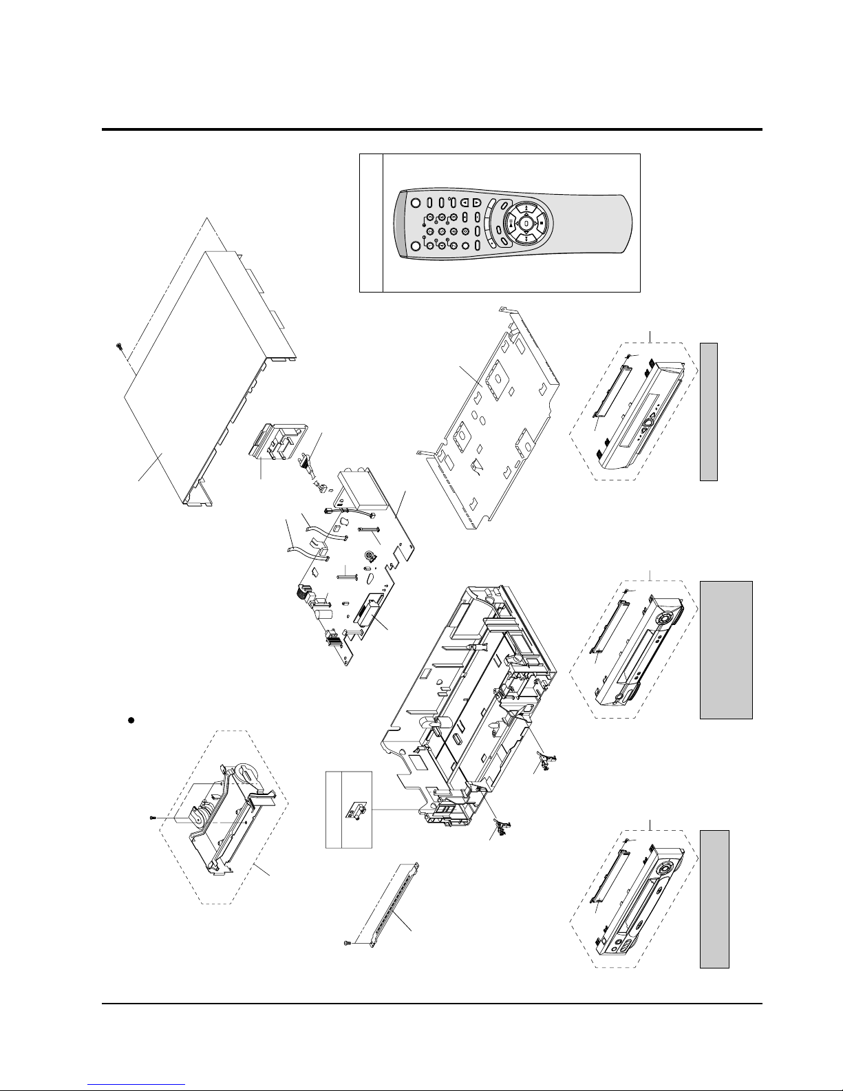
3-1 Cabinet Assembly
SV-434F/234F/435XV/235XV/233XV
SV-435GV/235GV/D35G
SV-431F/231F/233BV/231BV/230BV
SV-433XV/431XV/4313XV/231XV
SV-2315XV/2313XV/230XV/230XDV
SV-430GV/230GV/21
1
21
22
1 1
21
21
22
22
SV-2300X/D2300G/D1111
157
BRACKET-FRAME
(S.N.A.)
MAIN PCB (S.N.A.)
102
200
TM401B
101
155
LED PCB (S.N.A.)
S601A
S602A
LD601S
CN602S
CN3A1S
UT01
VCR STANDBY/ON
TV STANDBY/ON
TV
SLOW
VCR
DISP./
SHUTTLE
V-LOCK
CLR/RST F.ADV
-/-INPUT INDEX
VOL PROG/TRK
R
E
C
M
E
N
U
A
U
D
I
O
S
P
E
E
D
D
U
B
REPEAT
OK
SAT
153
FULL DECK (S.N.A.)
56
55
F-A/V PCB (S.N.A.)
S.N.A. : Service Not Available
Exploded View and Parts List
Samsung Electronics 3-3
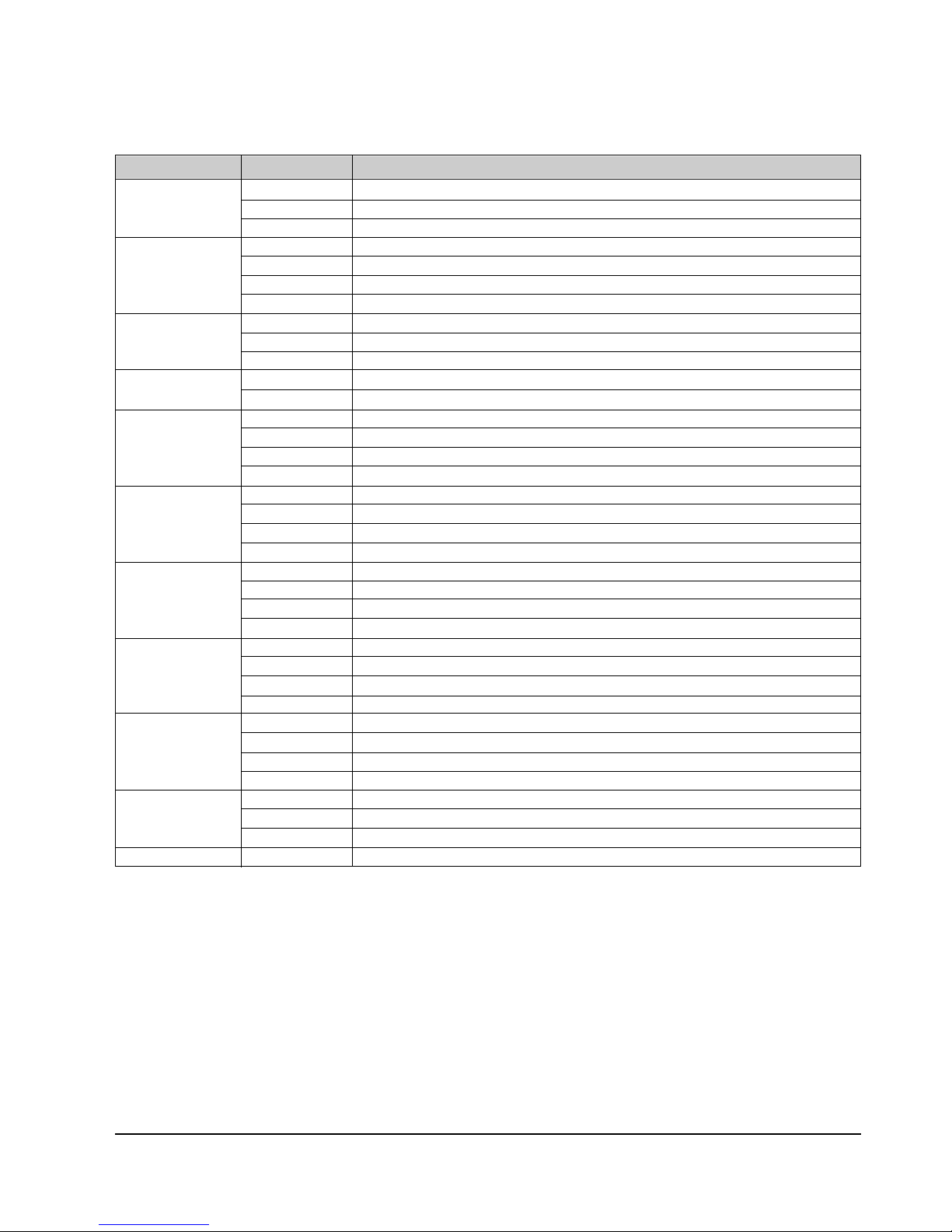
Loc. No Parts No. Description ; Specification Remark
1
Refer to table below
ASSY-PANEL FRONT
21
Refer to table below
DOOR-CASSETTE
22 AC61-62032A SPRING-MASK
55 AC61-30164D LOCKER-CODO ASSY L;-,LUCEL+SECC+SUS,-,- OPTIONAL
56 AC61-30164C LOCKER-CODO ASSY R;-,LUCEL+SECC+SUS,-,- OPTIONAL
101
Refer to table below
CABINET TOP-;SV-2300X,-,PCM(SECC),-,SV-2
102 AC63-00015A COVER-BOTTOM;-,SECC,-,T;0.5,SECC T0.5,-,
153 AC60-12126A SCREW-BH;-,BH,-,4*12,FE,FZY,-,-,155 AC60-12134A SCREW-TAP BH;-,BH,-,2-4X16,-,FE
157 AC60-10063A SCREW-TAPTITE;BH,+,-,M3,L12,ZPC3,SWRCH18
200 AC39-10019A POWER CORD;KKP-419C,H03VVH2-F,VDE/KEMA-K COMMON
AC39-12022K POWER-CORD;Y352160,H03VVH2-F,-,BS6500 U.K.ONLY
CN3A1S 3809-001111 CABLE-FLAT;30V,80C,130mm,7P,1.25mm,UL289
CN602S 3809-001110 CABLE-FLAT;30V,80C,150mm,7P,1.25mm,UL289
LD601A AC61-21009A HOLDER-LED;-,POM(M90-44),-,BLK,-,X-9
S601A AC61-21008A HOLDER-SENSOR;-,POM(M90-44),-,BLK,-,X-9
S602A AC61-21008A HOLDER-SENSOR;-,POM(M90-44),-,BLK,-,X-9
TM401B
Refer to table below
CHASSIS;SV-433FV/XEF,HIPS94HB,T2,-,128
UT01
Refer to table below
REMOCON-ASSY;-,NR4834,-,34KEY,TWIN_V_PAL
COUNTRY MODELS 1 2 101 TM401B UT01
France SV-434F AC97-00999D AC64-00388J AC64-00400A AC61-00095A AC59-00017J
SV-431F AC97-01154A AC64-00445D AC64-00400A AC61-00095A AC59-00017F
SV-234F AC97-00999G AC64-00388Q AC64-00400A AC61-00095A AC59-00017J
SV-231F AC97-01151A AC64-00445E AC64-00400A AC61-00095A AC59-00017F
U.K. SV-233BV AC97-01119A AC64-00313S AC64-00400A AC61-00095B AC59-00017H
SV-231BV AC97-01179A AC64-00313U AC64-00400A AC61-00095B AC59-00017H
SV-230BV AC97-01142A AC64-00313T AC64-00400A AC61-00095B AC59-00017G
Germany SV-435XV AC97-00999E AC64-00388K AC64-00400A AC61-00095A AC59-00017E
Spain SV-431XV AC97-01143A AC64-00445F AC64-00400A AC61-00095A AC59-00017G
SV-235XV AC97-00597Z AC64-00388S AC64-00400A AC61-00095A AC59-00017G
SV-231XV AC97-01120A AC64-00445A AC64-00400A AC61-00095A AC59-00017G
Italy SV-435XV AC97-00999F AC64-00388N AC64-00400A AC61-00095A AC59-00017E
SV-431XV AC97-01144A AC64-00445G AC64-00400B AC61-00095A AC59-00017B
SV-4313XV AC97-01145A AC64-00445H AC64-00400A AC61-00095A AC59-00017G
SV-235XV AC97-00999H AC64-00388R AC64-00400A AC61-00095A AC59-00017E
SV-231XV AC97-01121A AC64-00445B AC64-00400B AC61-00095A AC59-00017B
SV-2315XV AC97-01147A AC64-00445J AC64-00400A AC61-00095A AC59-00017G
SV-2313XV AC97-01146A AC64-00445K AC64-00400A AC61-00095A AC59-00017G
Portugal SV-431XV AC97-01144A AC64-00445G AC64-00400B AC61-00095A AC59-00017B
SV-231XV AC97-01121A AC64-00445B AC64-00400B AC61-00095A AC59-00017B
Denmark SV-435XV AC97-00999F AC64-00388N AC64-00400A AC61-00095A AC59-00017E
SV-431XV AC97-01143A AC64-00445F AC64-00400A AC61-00095A AC59-00017G
SV-235XV AC97-00999H AC64-00388R AC64-00400A AC61-00095A AC59-00017E
SV-230XV AC97-01152A AC64-00445L AC64-00400A AC61-00095B AC59-00017G
SV-2300X AC97-01069F AC64-00393A AC64-00400A AC61-00095B AC59-00017G
Sweden/Finland SV-435XV AC97-00999F AC64-00388N AC64-00400A AC61-00095A AC59-00017E
SV-431XV AC97-01143A AC64-00445F AC64-00400A AC61-00095A AC59-00017G
SV-235XV AC97-00999H AC64-00388R AC64-00400A AC61-00095A AC59-00017E
SV-230XV AC97-01152A AC64-00445L AC64-00400A AC61-00095B AC59-00017G
SV-2300X AC97-01069F AC64-00393A AC64-00400A AC61-00095B AC59-00017G
Exploded View and Parts List
3-4 Samsung Electronics
COUNTRY MODELS 1 21 51 101 TM401B
Norway SV-435XV AC97-00999F AC64-00388N AC64-00400A AC61-00095A AC59-00017E
SV-431XV AC97-01143A AC64-00445F AC64-00400A AC61-00095A AC59-00017G
SV-235XV AC97-00999H AC64-00388R AC64-00400A AC61-00095A AC59-00017E
SV-230XV AC97-01152A AC64-00445L AC64-00400A AC61-00095B AC59-00017G
Netherlands SV-435XV AC97-00999F AC64-00388N AC64-00400A AC61-00095A AC59-00017E
SV-431XV AC97-01143A AC64-00445F AC64-00400A AC61-00095A AC59-00017G
SV-235XV AC97-00999H AC64-00388R AC64-00400A AC61-00095A AC59-00017E
SV-230XV AC97-01162A AC64-00445S AC64-00400B AC61-00095B AC59-00017B
SV-230XDV AC97-01152A AC64-00445L AC64-00400A AC61-00095B AC59-00017G
Switzerland SV-435XV AC97-00999F AC64-00388N AC64-00400A AC61-00095A AC59-00017E
SV-433XV AC97-01148A AC64-00445M AC64-00400A AC61-00095A AC59-00017E
SV-233XV AC97-01138C AC64-00388V AC64-00400A AC61-00095B AC59-00017E
SV-230XV AC97-01153A AC64-00445N AC64-00400B AC61-00095B AC59-00017B
Austria SV-435XV AC97-00999F AC64-00388N AC64-00400A AC61-00095A AC59-00017E
SV-433XV AC97-01148A AC64-00445M AC64-00400A AC61-00095A AC59-00017E
SV-233XV AC97-01138C AC64-00388V AC64-00400A AC61-00095B AC59-00017E
SV-230XV AC97-01153A AC64-00445N AC64-00400B AC61-00095B AC59-00017B
Greece SV-435XV AC97-00999F AC64-00388N AC64-00400A AC61-00095A AC59-00017E
SV-431XV AC97-01144A AC64-00445G AC64-00400B AC61-00095A AC59-00017B
SV-230XV AC97-01153A AC64-00445N AC64-00400B AC61-00095B AC59-00017B
Cyprus SV-435XV AC97-00999F AC64-00388N AC64-00400A AC61-00095A AC59-00017E
SV-431XV AC97-01144A AC64-00445G AC64-00400B AC61-00095A AC59-00017B
SV-230XV AC97-01153A AC64-00445N AC64-00400B AC61-00095B AC59-00017B
Croatia SV-435XV AC97-00999F AC64-00388N AC64-00400A AC61-00095A AC59-00017E
SV-431XV AC97-01144A AC64-00445G AC64-00400B AC61-00095A AC59-00017B
SV-235XV AC97-01138A AC64-00388T AC64-00400A AC61-00095A AC59-00017E
SV-230XV AC97-01153A AC64-00445N AC64-00400B AC61-00095B AC59-00017B
Slovenia SV-435XV AC97-00999F AC64-00388N AC64-00400A AC61-00095A AC59-00017E
SV-431XV AC97-01144A AC64-00445G AC64-00400B AC61-00095A AC59-00017B
SV-233XV AC97-01138C AC64-00388V AC64-00400A AC61-00095A AC59-00017E
Yugo SV-435XV AC97-00999F AC64-00388N AC64-00400A AC61-00095A AC59-00017E
SV-233XV AC97-01138C AC64-00388V AC64-00400A AC61-00095A AC59-00017E
Hungary SV-435GV AC97-00597Y AC64-00388P AC64-00400A AC61-00095A AC59-00016C
SV-430GV AC97-01150A AC64-00445P AC64-00400B AC61-00095B AC59-00017B
SV-235GV AC97-01138B AC64-00388U AC64-00400A AC61-00095A AC59-00017E
SV-230GV AC97-01149A AC64-00445Q AC64-00400B AC61-00095B AC59-00017B
Romania SV-435GV AC97-00597Y AC64-00388P AC64-00400A AC61-00095A AC59-00016C
SV-430GV AC97-01150A AC64-00445P AC64-00400B AC61-00095B AC59-00017B
SV-235GV AC97-01138B AC64-00388U AC64-00400A AC61-00095A AC59-00017E
SV-230GV AC97-01149A AC64-00445Q AC64-00400B AC61-00095B AC59-00017B
Czech. SV-435GV AC97-00597Y AC64-00388P AC64-00400A AC61-00095A AC59-00016C
SV-430GV AC97-01150A AC64-00445P AC64-00400B AC61-00095B AC59-00017B
SV-235GV AC97-01138B AC64-00388U AC64-00400A AC61-00095A AC59-00017E
SV-230GV AC97-01149A AC64-00445Q AC64-00400B AC61-00095B AC59-00017B
Bulgaria SV-435GV AC97-00597Y AC64-00388P AC64-00400A AC61-00095A AC59-00016C
Macedonia SV-430GV AC97-01150A AC64-00445P AC64-00400B AC61-00095B AC59-00017B
SV-235GV AC97-01138B AC64-00388U AC64-00400A AC61-00095A AC59-00017E
SV-230GV AC97-01149A AC64-00445Q AC64-00400B AC61-00095B AC59-00017BA
<Continued>
 Loading...