

Page 1
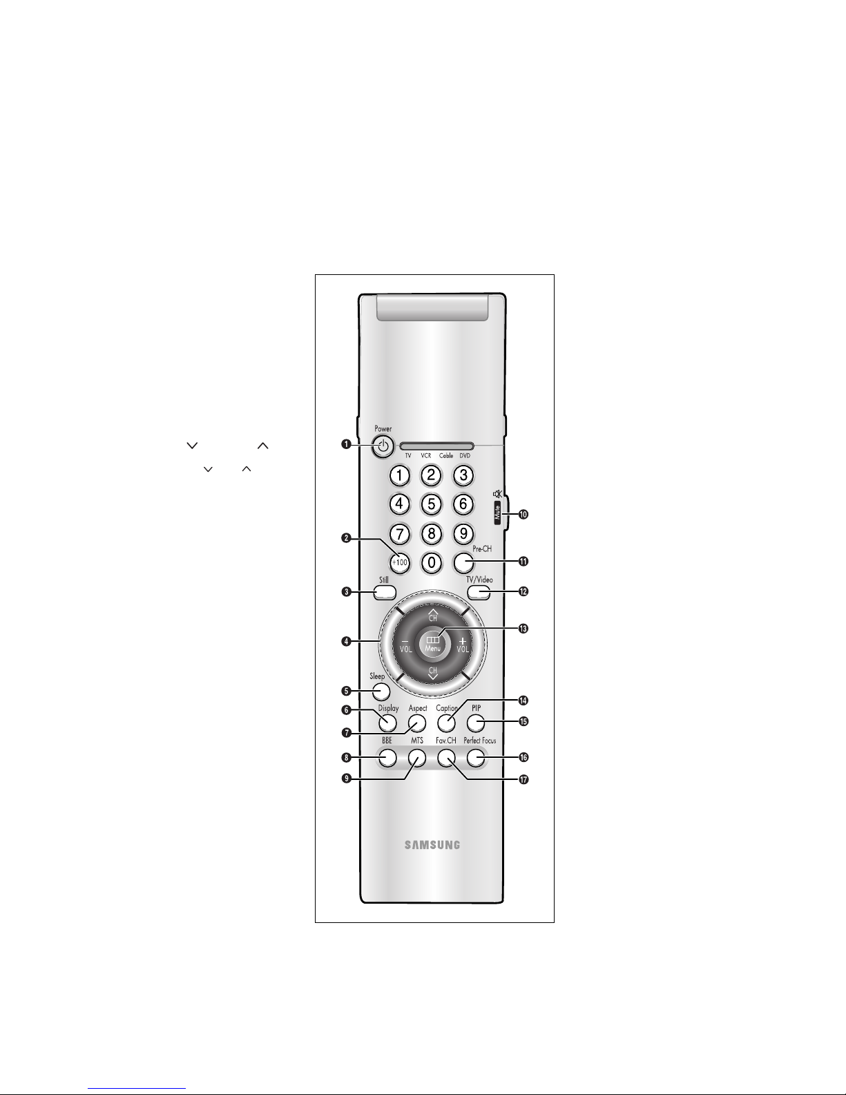
Remote Control
You can use the remote control up to about 23 feet from the TV. When using the remote,
always point it directly at the TV.
You can also use your remote control to operate your VCR and cable box.
Œ
Power
Turns the TV on and off.
´
+100
Press to select channels over 100.
For example, to select channel
121, press “+100,” then press “2”
and “1.”
ˇ
Still(Main)
Press to stop the action during a
particular scene. Press again to
resume normal video.
¨
CH and CH
(Channel Up/Down)
Press CH or CH to change
channels.
VOL -, VOL +
Press increase or decrease the
volume.
ˆ
Sleep
Press to select a preset time interval for automatic shutoff.
Ø
Display
Press to display the current channel and the audio-video
settings.
∏
Aspect
Press to change the screen size.
”
BBE
BBE is a built-in effect that adds
clarity, punch and dynamics to the
sound.
’
MTS (Multichannel
Television Sound)
Press to choose stereo, mono or
Separate Audio Program (SAP
broadcast).
˝
Mute
Press to temporarily cut off
the sound.
Ô
Pre-CH
Tunes to the previous channel.
TV/Video
All the inputs connected to the
external component jacks will be
shown in regular sequence.
Ò
Menu
Displays the main on-screen
menu.
Ú
Caption
Controls the caption decoder.
Æ
PIP
Activates picture in picture.
ı
Perfect Focus
Press to adjust for the optimum
picture set in the Factory.
˜
Fav. CH (Favorite
Channel)
Press to switch between your
favorite channels.
Page 2
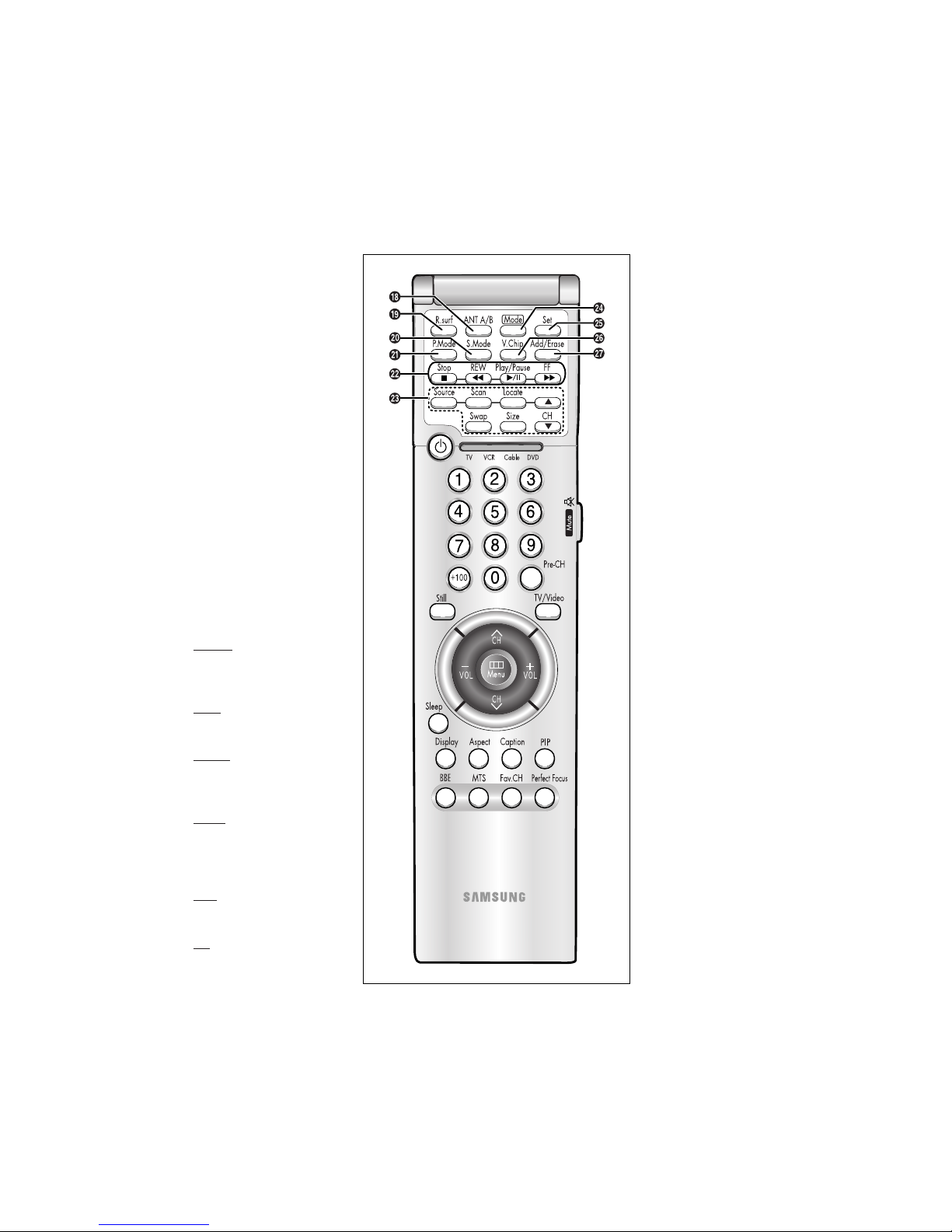
Remote Control (continued)
¯
ANT A/B
Press to select the ANT A or ANT
B.
˘
R.surf
Press to automatically return to a
preferred channel after a userpreset time delay.
¿
S.Mode
Adjust the TV sound by selecting
one of the preset factory settings
(or select your personal, customized sound settings).
¸
P.Mode
Adjust the TV picture by selecting one of the preset factory settings (or select your personal,
customized picture settings).
˛
VCR controls
Controls VCR tape functions:
Rewind, Play, Fast Forward, Stop,
Pause.
◊
PIP Controls
Source
Press to select one of the available signal sources for the PIP
window.
Scan
Press to memorize (scan) the
available channels.
Locate
Press to move the PIP window to
any of the four corners of the TV
screen.
Swap
Exchanges the video signal that
is currently displayed on the
main screen with the signal in
the PIP window.
Size
Press to make the PIP window
large, small or stock ticker.
CH
Displays the available channels
in sequence. (These buttons
change channels in the PIP window only).
±
Mode
Selects a target device to be
controlled by the Samsung
remote control(i.e., TV, VCR,
Cable box or DVD).
≠
Set
Used during set up of this
Samsung remote control, so that
it will work compatibly with
other devices (VCR, cable box,
DVD.)
–
V.Chip
Press to set up and activate the
parental locks. (Not available)
—
Add/Erase
Press to add or erase channels
in the TV’s memory.
Page 3
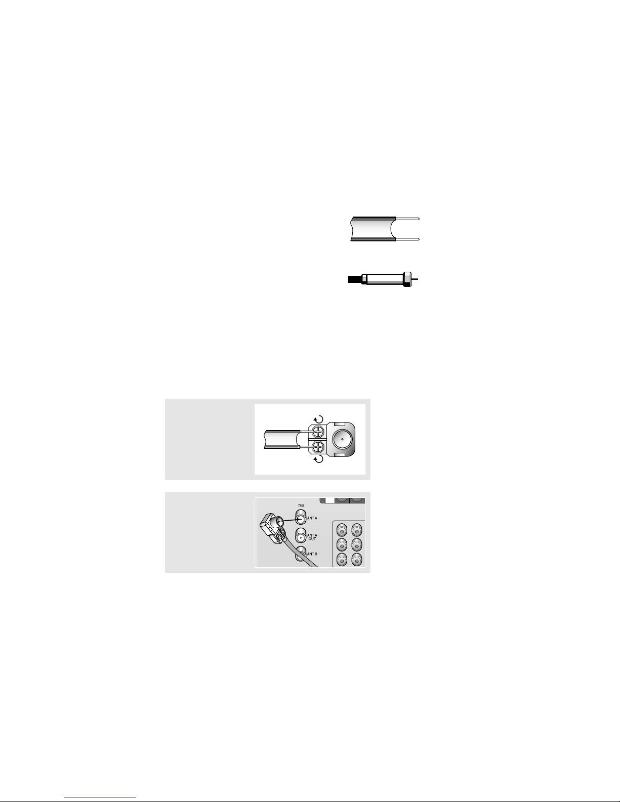
Connecting VHF and UHF Antennas
If your antenna has a set of leads that
look like this, see “Antennas with
300-ohm Flat Twin Leads,” below.
If your antenna has one lead that looks
like this, see Antennas with 75-ohm
Round Leads.
If you have two antennas, see Separate
VHF and UHF Antennas.
Antennas with 300-ohm Flat Twin Leads
If you are using an off-air antenna (such as a roof antenna or “rabbit ears”) that has 300ohm twin flat leads, follow the directions below.
Chapter Two
1
Place the wires from the
twin leads under the
screws on the 300-75
ohm adaptor (not supplied). Use a screwdriver
to tighten the screws.
2
Plug the adaptor into the
ANT-A or ANT-B terminal
on the rear panel.
2
Page 4
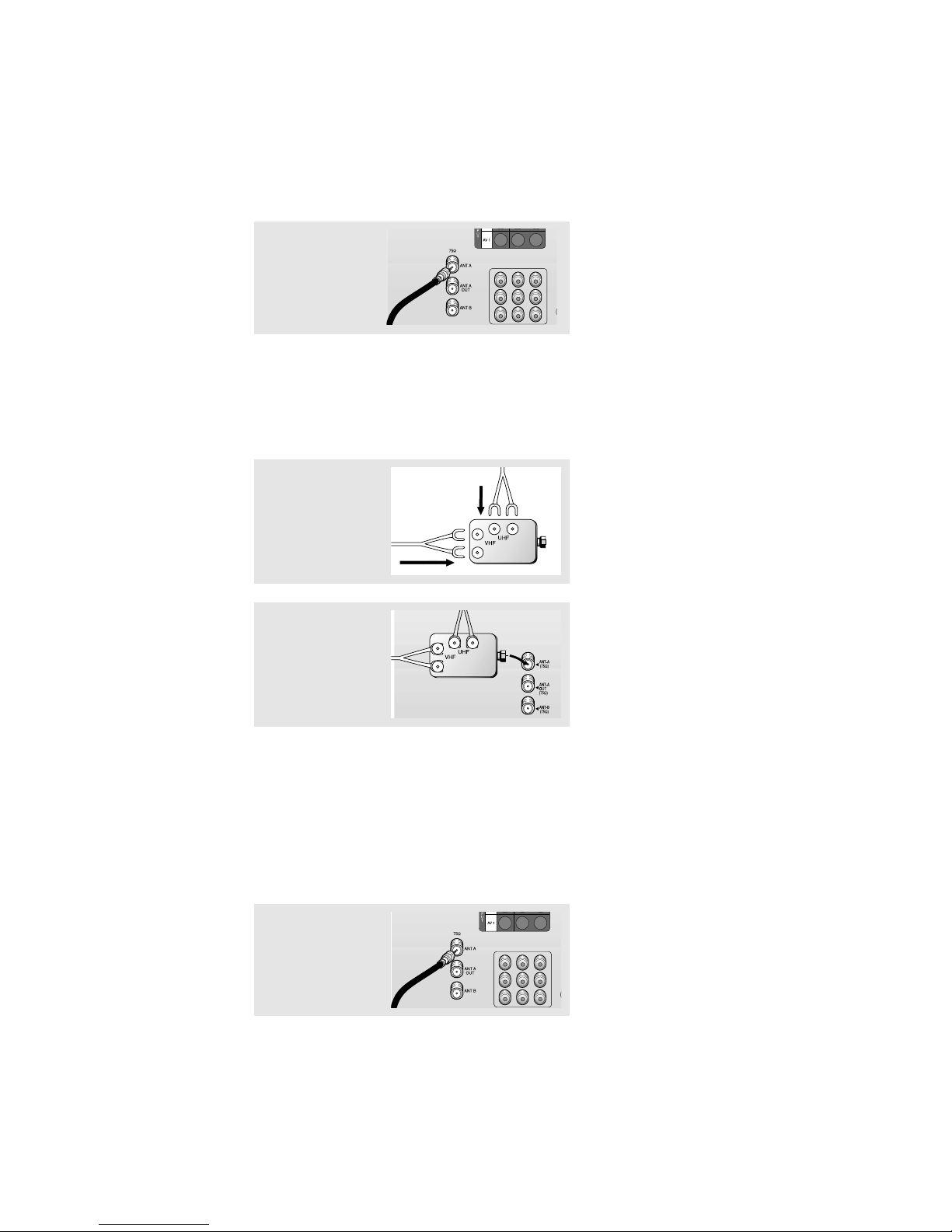
Connecting Cable TV
You can connect different cable systems to your TV, including cable without a cable box,
and cable with a cable box that descrambles some or all channels.
Cable without a Cable Box
If you want to connect cable, and you do not need to use a cable box:
Plug the incoming cable
into the ANT-A or ANT-B
antenna terminal on the
rear of the TV.
2
Plug the combiner into
the ANT-A or ANT-B terminal on the rear panel.
Antennas with 75-ohm Round Leads
Plug the antenna lead
into the ANT-A or ANT-B
terminal on the rear
panel.
Separate VHF and UHF Antennas
If you have two separate antennas for your TV (one VHF and one UHF), you must combine
the two antenna signals before connecting the antennas to the TV. This procedure requires a
an optional combiner-adaptor (available at most electronics shops).
1
Connect both antenna
leads to the combiner.
Page 5
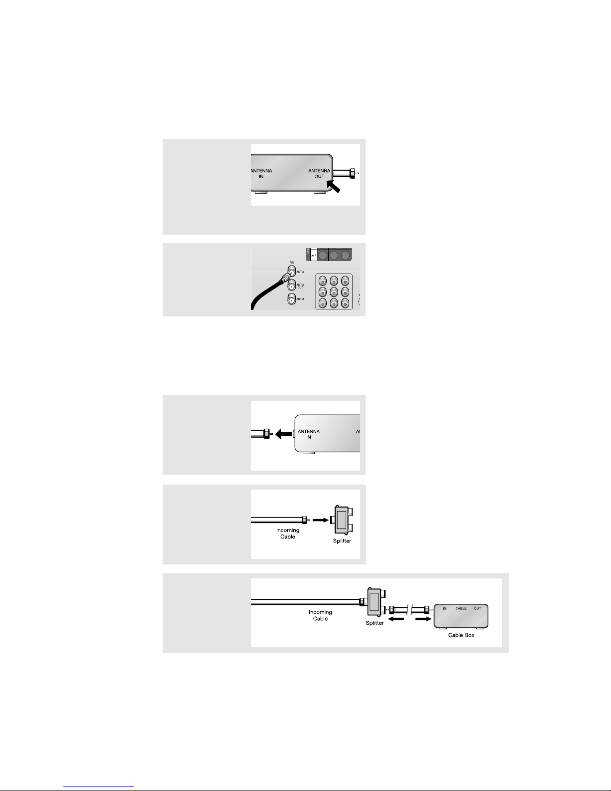
Cable with a Cable box that Descrambles All Channels
1
Find the cable that is
connected to the
ANTENNA OUT terminal
on your cable box. This
terminal might be
labeled “ANT OUT”,
“VHF OUT”, or simply,
“OUT”.
2
Connect the other end of
this cable to the ANT-A
or ANT-B terminal on the
rear of the TV.
▼
This terminal might be labeled
“ANT IN,” “VHF IN,” or simply,
“IN.”
Connecting to a Cable Box that Descrambles Some Channels
If your cable box descrambles only some channels (such as premium channels), follow the
instructions below. You will need a two-way splitter, an RF (A/B) switch, and four lengths of
coaxial cable. (These items are available at most electronics stores.)
1
Find and disconnect the
cable that is connected
to the ANTENNA IN terminal on your cable box.
2
Connect this cable to a
two-way splitter.
3
Connect a coaxial cable
between an OUTPUT terminal on the splitter and
the IN terminal on the
cable box.
Page 6
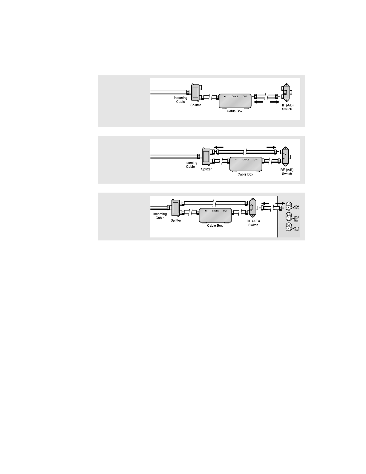
4
Connect a coaxial cable
between the ANTENNA
OUT terminal on the
cable box and the B–IN
terminal on the A/B
switch.
5
Connect another cable
between the other OUT
terminal on the splitter
and the A–IN terminal on
the RF (A/B) switch.
6
Connect the last coaxial
cable between the OUT
terminal on the RF (A/B)
switch and the VHF/UHF
terminal on the rear of
the TV.
After you’ve made this connection, set the A/B switch to the “A” position for normal viewing. Set the A/B switch to the “B” position to view scrambled channels. (When you set the
A/B switch to “B,” you will need to tune your TV to the cable box’s output channel, which is
usually channel 3 or 4.)
Page 7
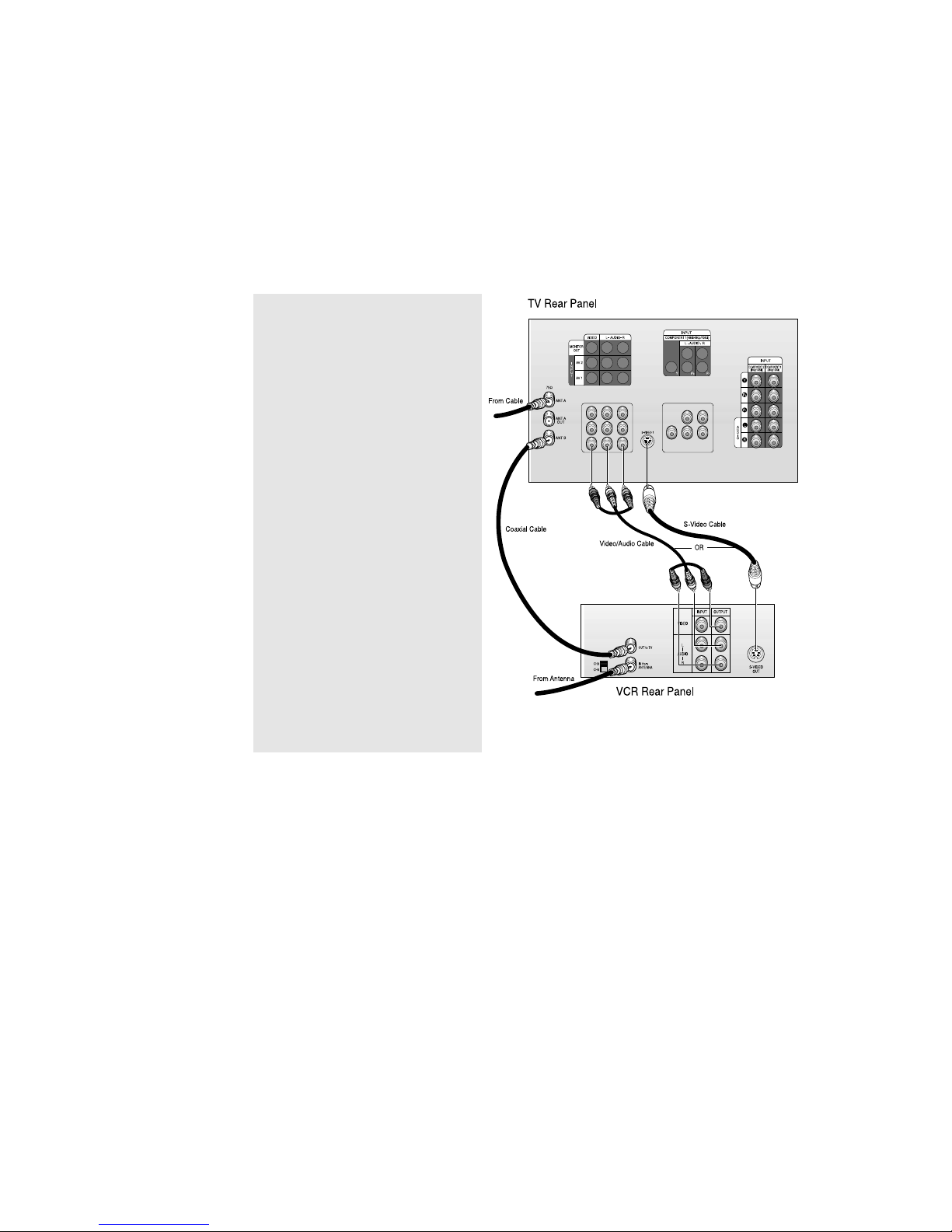
Connecting a VCR
These instructions assume that you have already connected your TV to an antenna or a
cable TV system . Skip step 1 if you have
not yet connected to an antenna or a cable system.
1
Connect a coaxial cable between the
ANTENNA OUT terminal on the VCR and the
antenna terminal on the TV.
A coaxial cable is usually included with a
VCR. (If not, check your local electronics
store).
2
Connect a set of audio cables between the
AUDIO OUTjacks on the VCR and the
AUDIO jacks on the TV.
If you have a mono VCR, connect L(mono)
to VCR audio out using only one audio
cable.
3
Connect a video cable between the VIDEO
OUT jack on the VCR and the VIDEO jack on
the TV.
If you have a S-VHS VCR, use the S-Video
connections and remove the video cable.
Do not connect the video cable and the SVideo cable to video 1 simultaneously.
Follow the instructions in “Viewing a VCR
or Camcorder Tape” to view your VCR tape.
Note: This figure shows the Standard Connector-jack panel. The actual configuration on your TV may
be different, depending on the model.
Page 8
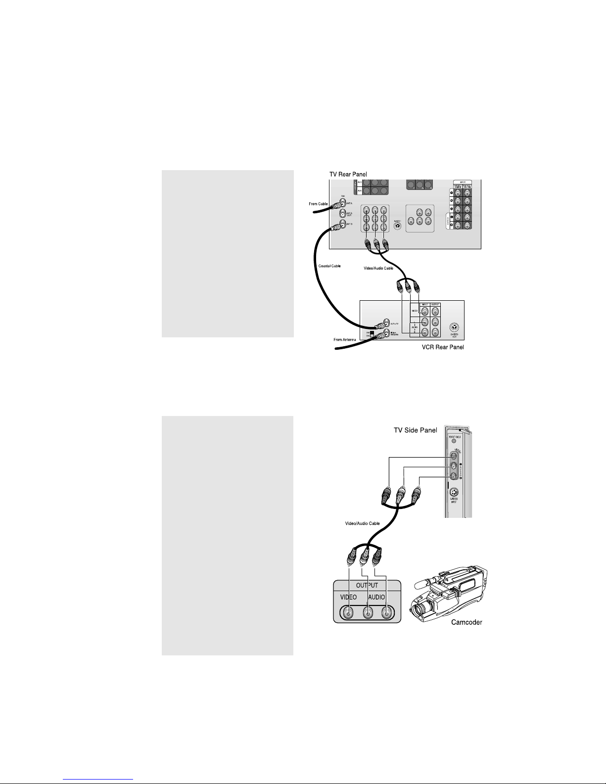
Connecting a Camcorder
The side panel jacks on your TV make it easy to connect a camcorder to your TV. They allow
you to view the camcorder tapes without using a VCR.
1
Locate the A/V output jacks on the
camcorder. They are usually found on
the side or rear of the camcorder.
2
Connect an audio cable between the
AUDIO OUTPUT jack on the camcorder
and the AUDIO terminals on the side of
the TV.
If you have mono camcorder, connect
L(mono) to camcorder audio out using
only one audio cable.
3
Connect a video cable between the
VIDEO OUTPUT jack on the camcorder
and the VIDEO terminal on the sidet of
the TV.
The audio-video cables shown here are
usually included with a Camcorder. (If
not, check your local electronics store.)
If your camcorder is stereo, you need to
connect a set of two cables.
Connecting a Second VCR to Record from the TV
Your TV can send out signals of its picture and sound to be recorded by a second VCR. To do
this, connect your second VCR as follows:
1
Connect a set of audio cables between
the AUDIO OUT jacks on the TV and the
AUDIO IN jacks on the VCR.
(The VCR input jacks might be either
on the front or rear of the VCR.)
2
Connect a video cable between the
VIDEO OUT jack on the TV and the
VIDEO IN jack on the VCR.
Refer to your VCR’s instructions for
more information about how to record
using this kind of connection.
Note: This figure shows the Standard Connector-jack panel. The actual configuration on your TV may
be different, depending on the model.
Page 9
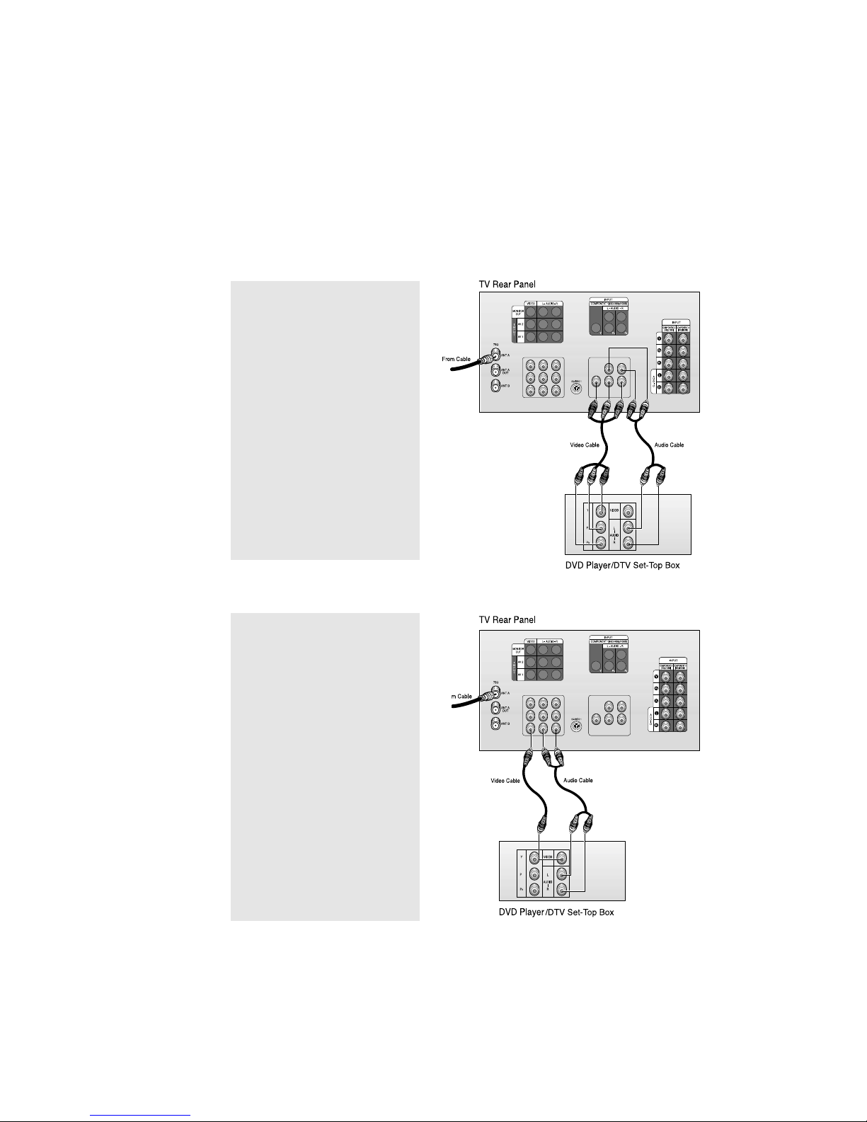
Connecting a DVD Player, DTV Set-Top Box
(480i, 480p, 1080i)
The rear panel jacks on your TV make it easy to connect a DVD player (or DTV Set-Top
Box) to your TV.
Connecting to Y, PB, P
R
1
Connect a set of audio cables between
the DVD audio in jacks on the TV and
the AUDIO OUT jacks on the DVD player
(or DTV Set-Top Box).
2
To enable Component video viewing,
connect video cables between the Y, PB,
and PRinputs on the TV and Y, PB, and P
R
(or Y, CB, CR) outputs on the DVD player
(or DTV Set-Top Box).
Note: For an explanation of
Component video, see your DVD
player’s (or DTV Set-Top Box) owner’s
instruction.
Connecting to regular audio and video jacks
1
Connect a set of audio cables between
the AUDIO IN jacks on the TV and the
AUDIO OUT jacks on the DVD player
(or DTV Set-Top Box).
2
Connect video cables between the
VIDEO OUT jack on the DVD player
(or DTV Set-Top Box) and the VIDEO
IN jack on the TV.
Note: This figure shows the Standard Connector-jack panel. The actual configuration on your TV may
be different, depending on the model.
Page 10
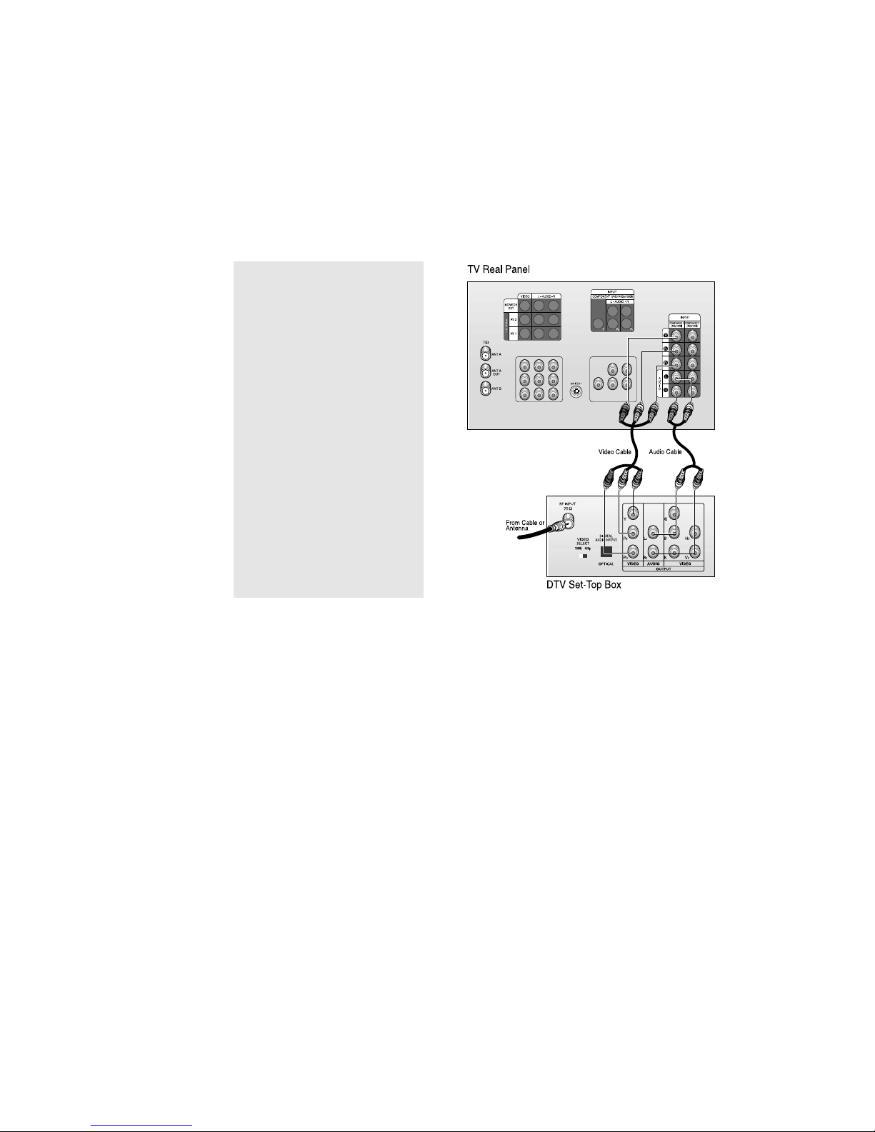
Connecting a DTV Set-Top Box (480p, 1080i)
When switching to the DTV mode, either 480p or 1080i format is automatically selected
according to the input signal.
Note: Only 480p and 1080i formats are supported.
1
Connect a set of audio cables between
the DTV Set-Top Box audio in jacks on
the TV and the AUDIO OUT jacks on the
DTV Set-Top box.
2
To enable Component video viewing,
connect video cables between the Y, PB,
and PRinputs on the TV and Y, PB, and P
R
(or Y, CB, CR) outputs on the DTV Set-Top
box.
Note: For an explanation of
Component video, see your DTV Settop box’s owner’s instruction.
 Loading...