

Page 1

ST-54T6
ST-62T6
................................................................................................................
COLOR TELEVISION
Printed in Mexico
AA68-01791A(ENG)
.............
Owner’s
Instructions
Page 2
Warning! Important
Safety Instructions
CAUTION
RISK OF ELECTRIC SHOCK
DO NOT OPEN
CAUTION: TO REDUCE THE RISK OF ELECTRIC SHOCK, DO NOT
REMOVE COVER (OR BACK). NO USER SERVICEABLE PARTS INSIDE.
REFER SERVICING TO QUALIFIED SERVICE PERSONNEL.
This symbol indicates high voltage is present inside. It is
dangerous to make any kind of contact with any inside part of
this product.
This symbol alerts you that important literature concerning
operation and maintenance has been included with this product.
Note to CATV system installer: This reminder is provided to call CATV, that provides guidelines for proper grounding and, in particular, specifies that the cable
ground shall be connected to the grounding system of the building as close to the
point of cable entry as practical.
Important: One Federal Court has held that unauthorized recording of
copyrighted TV programs is an infringement of U.S. copyright laws.
Certain Canadian programs may also be copyrighted and any unauthorized
recording in whole or in part may be in violation of these rights.
To prevent damage which may result in fire or electric shock
hazard, do not expose this appliance to rain or moisture.
Page 3

Thank You for Choosing Samsung
Thank you for choosing Samsung! Your new Samsung Projection TV represents the latest in
television technology. We designed it with easy-to-use on-screen menus and closed captioning
capabilities, making it one of the best products in its class. We are proud to offer you a product
that will provide convenient, dependable service and enjoyment for years to come.
Important Safety Information
Always be careful when using your TV receiver. To reduce the risk of fire, electrical shock,
and other injuries, keep these safety precautions in mind when installing, using, and
maintaining your machine.
• Read all safety and operating instructions before operating your TV.
• Keep the safety and operating instructions for future reference.
• Heed all warnings on the TV receiver and in the operating instructions.
• Follow all operating and use instructions.
• Unplug the TV receiver from the wall outlet before cleaning. Use a damp cloth; do not use
liquid or aerosol cleaners.
• Never add any attachments and/or equipment without approval of the manufacturer. Such
additions can increase the risk of fire, electric shock, or other personal injury.
• Do not use the TV receiver where contact with or immersion in water is a possibility, such as
near bath tubs, sinks, washing machines, swimming pools, etc.
• Do not place the TV on an unstable cart, stand, tripod, bracket, or
table where it can fall. A falling TV can cause serious injury to a
child or adult, and serious damage to the appliance. Use only with
a cart, stand, tripod, bracket, or table recommended by the manufacturer or sold with the TV. Follow the manufacturer’s instructions when mounting the unit, and use a mounting accessory recommended by the manufacturer. Move the TV and cart with care.
Quick stops, excessive force, and uneven surfaces can make the
unit and cart unsteady and likely to overturn.
•Provide ventilation for the TV receiver. The unit is designed with slots in the cabinet for ventilation to protect it from overheating. Do not block these openings with any object, and do
not place the TV receiver on a bed, sofa, rug, or other similar surface. Do not place it near a
radiator or heat register. If you place the TV receiver on a rack or bookcase, ensure that there
is adequate ventilation and that you’ve followed the manufacturer’s instructions for mounting.
• Operate your TV receiver only from the type of power source indicated on the marking label.
If you are not sure of the type of power supplied to your home, consult your appliance dealer
or local power company.
• Use only a grounded or polarized outlet. For your safety, this TV is equipped with a polarized
alternating current line plug having one blade wider than the other. This plug will fit into the
power outlet only one way. If you are unable to insert the plug fully into the outlet, try
reversing the plug. If the plug still does not fit, contact your electrician to replace your outlet.
SAFETY 1
Page 4
•Protect the power cord. Power supply cords should be routed so that they won’t be walked on
or pinched by objects placed on or against them. Pay particular attention to cords at plugs, convenience receptacles, and the point where they exit from the unit.
• Unplug the TV from the wall outlet and disconnect the antenna or cable system during a lightning storm or when left unattended and unused for long periods of time. This will prevent damage to the unit due to lightning and power-line surges.
•Avoid overhead power lines. An outside antenna system should not be placed in the vicinity of
overhead power lines or other electric light or power circuits or where it can fall into such
power lines or circuits. When installing an outside antenna system, be extremely careful to keep
from touching the power lines or circuits. Contact with such lines can be fatal.
•Do not overload the wall outlet or extension cords. Overloading can result in fire or electric
shock.
• Do not insert anything through the openings in the unit, where they can touch dangerous voltage points or damage parts. Never spill liquid of any kind on the TV.
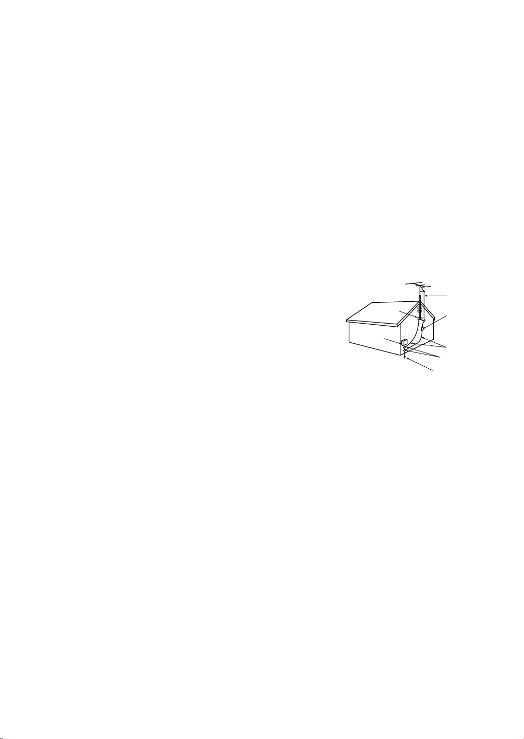
•Ground outdoor antennas. If an outside antenna or cable
system is connected to the TV, be sure the antenna or
cable system is grounded so as to provide some
protection against voltage surges and built-up static
charges. Section 810 of the National Electrical Code,
ANSI/NFPA No.70-1984, provides information about
proper grounding of the mast and supporting structure,
grounding of the lead-in wire to an antenna discharge
unit, size of grounding conductors, location of antenna
discharge unit, connection to grounding electrodes, and
EXAMPLE OF
ANTENNA GROUNDING
GROUND CLAMP
ELECTRIC
SERVICE
EQUIPMENT
NEC — NATIONAL ELECTRICAL CODE
ANTENNA
LEAD IN WIRE
ANTENNA
DISCHARGE UNIT
(NEC SECTION 810-20)
GROUNDING
CONDUCTORS
(NEC SECTION 810-21)
GROUND CLAMPS
POWER SERVICE GROUNDING
ELECTRODE SYSTEM
(NEC ART 250, PART H)
requirements for the grounding electrode.
• Do not attempt to service the TV yourself. Refer all servicing to qualified service personnel.
Unplug the unit from the wall outlet and refer servicing to qualified service personnel under the
following conditions:
- when the power-supply cord or plug is damaged
- if liquid has been spilled on the unit or if objects have fallen into the unit
- if the TV has been exposed to rain or water
- if the TV does not operate normally by following the operating instructions
- if the TV has been dropped or the cabinet has been damaged
- when the TV exhibits a distinct change in performance
• If you make adjustments yourself, adjust only those controls that are covered by the operating
instructions. Adjusting other controls may result in damage and will often require extensive
work by a qualified technician to restore the TV to normal.
• When replacement parts are required, be sure the service technician uses replacement parts
specified by the manufacturer or those that have the same characteristics as the original part.
Unauthorized substitutions may result in additional damage to the unit.
2 SAFETY
• Upon completion of any service or repairs to this TV, ask the service technician to
perform safety checks to determine that the TV is in a safe operating condition.
Page 5

C
ONTENTS
Chapter 1: Your New TV . . . . . . . . . . . . . . .1.1
List of Features . . . . . . . . . . . . . . . . . . . . . . . . . . . . . . . . . . . . . . . . . 1.1
Familiarizing Yourself with Your New TV . . . . . . . . . . . . . . . . . . . . . 1.2
Front Panel Buttons . . . . . . . . . . . . . . . . . . . . . . . . . . . . . . 1.2
Front/Side Panel Jacks . . . . . . . . . . . . . . . . . . . . . . . . . . . . 1.3
Rear Panel Jacks . . . . . . . . . . . . . . . . . . . . . . . . . . . . . . . . . 1.4
Remote Control . . . . . . . . . . . . . . . . . . . . . . . . . . . . . . . . . 1.5
Chapter 2: Installation . . . . . . . . . . . . . . . . 2.1
Connecting VHF and UHF Antennas . . . . . . . . . . . . . . . . . . . . . . . . 2.1
Antennas with 300-ohm Flat Twin Leads . . . . . . . . . . . . . . 2.1
Antennas with 75-ohm Round Leads . . . . . . . . . . . . . . . . . 2.2
Separate VHF and UHF Antennas. . . . . . . . . . . . . . . . . . . . 2.2
Connecting Cable TV . . . . . . . . . . . . . . . . . . . . . . . . . . . . . . . . . . . . 2.2
Cable without a Cable Box . . . . . . . . . . . . . . . . . . . . . . . . . 2.2
Connecting to a Cable Box that Descrambles
All Channels. . . . . . . . . . . . . . . . . . . . . . . . . . . . . . . . . . . . 2.3
Connecting to a Cable Box that Descrambles
some Channels . . . . . . . . . . . . . . . . . . . . . . . . . . . . . . . . . . 2.3
Connecting a VCR . . . . . . . . . . . . . . . . . . . . . . . . . . . . . . . . . . . . . . 2.4
Connecting an S-VHS VCR. . . . . . . . . . . . . . . . . . . . . . . . . 2.5
Connecting a Second VCR to Record from the TV . . . . . . . 2.6
Connecting a Camcorder . . . . . . . . . . . . . . . . . . . . . . . . . . . . . . . . . 2.7
Installing Batteries in the Remote Control. . . . . . . . . . . . . . . . . . . . . 2.8
Chapter 3: Operation . . . . . . . . . . . . . . . . . . 3.1
Tu r ning the TV On and Off. . . . . . . . . . . . . . . . . . . . . . . . . . . . . . . . 3.1
Adjusting basic convergence. . . . . . . . . . . . . . . . . . . . . . . . . . . . . . . 3.1
Adjust Red Convergence . . . . . . . . . . . . . . . . . . . . . . . . . . 3.2
Adjust Blue Convergence . . . . . . . . . . . . . . . . . . . . . . . . . . 3.2
Viewing the Menus and On-Screen Displays. . . . . . . . . . . . . . . . . . . 3.3
Viewing the Menus. . . . . . . . . . . . . . . . . . . . . . . . . . . . . . . 3.3
Viewing the Display . . . . . . . . . . . . . . . . . . . . . . . . . . . . . . 3.3
Selecting a Menu Language. . . . . . . . . . . . . . . . . . . . . . . . . . . . . . . . 3.4
Memorizing the Channels. . . . . . . . . . . . . . . . . . . . . . . . . . . . . . . . . 3.5
Selecting the Video Signal-source . . . . . . . . . . . . . . . . . . . . 3.5
Storing Channels in Memory (Automatic Method) . . . . . . . 3.6
Adding and Erasing Channels (Manual Method) . . . . . . . . 3.7
Changing Channels . . . . . . . . . . . . . . . . . . . . . . . . . . . . . . . . . . . . . 3.7
Using the Channel Buttons. . . . . . . . . . . . . . . . . . . . . . . . . 3.7
Directly Accessing Channels. . . . . . . . . . . . . . . . . . . . . . . . 3.7
Setting the Clock . . . . . . . . . . . . . . . . . . . . . . . . . . . . . . . . . . . . . . . 3.8
Adjusting the Volume . . . . . . . . . . . . . . . . . . . . . . . . . . . . . . . . . . . . 3.9
Using Mute. . . . . . . . . . . . . . . . . . . . . . . . . . . . . . . . . . . . . 3.9
Customizing the Picture . . . . . . . . . . . . . . . . . . . . . . . . . . . . . . . . . . 3.10
Using Automatic Picture Settings . . . . . . . . . . . . . . . . . . . . . . . . . . . 3.11
Customizing the Sound . . . . . . . . . . . . . . . . . . . . . . . . . . . . . . . . . . 3.12
Using Automatic Sound Settings. . . . . . . . . . . . . . . . . . . . . . . . . . . . 3.13
Viewing a VCR or Camcorder Tape. . . . . . . . . . . . . . . . . . . . . . . . . . 3.14
CONTENTS 1
Page 6

C
ONTENTS
Chapter 4: Special Features . . . . . . . . . . . . 4.1
Customizing Your Remote Control . . . . . . . . . . . . . . . . . . . . . . . . . . 4.1
Setting Up Your Remote Control to Operate Your
VCR . . . . . . . . . . . . . . . . . . . . . . . . . . . . . . . . . . . . . . . . . . 4.1
Setting Up Your Remote Control to Operate Your
Cable Box. . . . . . . . . . . . . . . . . . . . . . . . . . . . . . . . . . . . . . 4.2
Setting the On/Off Timer . . . . . . . . . . . . . . . . . . . . . . . . . . . . . . . . . 4.4
Setting the Sleep Timer. . . . . . . . . . . . . . . . . . . . . . . . . . . . . . . . . . . 4.5
Viewing Closed Captions . . . . . . . . . . . . . . . . . . . . . . . . . . . . . . . . . 4.6
Fine Tuning Channels. . . . . . . . . . . . . . . . . . . . . . . . . . . . . . . . . . . . 4.7
LNA(Low Noise Amplifier) . . . . . . . . . . . . . . . . . . . . . . . . . . . . . . . . 4.8
Special Audio Options: MTS and Headphones . . . . . . . . . . . . . . . . . 4.9
Choosing a Multi-Channel Sound (MTS) Soundtrack. . . . . 4.9
Using Wireless Headphones . . . . . . . . . . . . . . . . . . . . . . . . 4.10
Setting up Wireless Headphones with Picture-in-Picture. . . . 4.10
Viewing Picture-in-Picture . . . . . . . . . . . . . . . . . . . . . . . . . . . . . . . . 4.11
Activating Picture-in-Picture. . . . . . . . . . . . . . . . . . . . . . . . 4.11
Selecting a Signal Source (Antenna or Cable) for PIP . . . . . 4.12
Selecting a Signal Source (External A/V) for PIP . . . . . . . . . 4.12
Swapping the Contents of the PIP image and Main image . 4.12
Changing the PIP Channel . . . . . . . . . . . . . . . . . . . . . . . . . 4.13
Changing the Location (Rotating) the PIP Window . . . . . . 4.13
Freezing the PIP Image. . . . . . . . . . . . . . . . . . . . . . . . . . . . 4.13
Changing the Size of the PIP Window . . . . . . . . . . . . . . . . 4.13
Scanning the Available Channels . . . . . . . . . . . . . . . . . . . . 4.13
Using the V-Chip . . . . . . . . . . . . . . . . . . . . . . . . . . . . . . . . . . . . . . . 4.14
Setting Up Your Personal ID Number (PIN) . . . . . . . . . . . . 4.14
How to Enable/Disable the V-Chip . . . . . . . . . . . . . . . . . . . 4.15
How to Set up Restrictions Using the “TV guidelines” . . . . 4.15
How to Set up Restrictions using the MPAA Ratings:
G, PG, PG-13, R, NC-17, X . . . . . . . . . . . . . . . . . . . . . . . . 4.17
How to Reset the TV after the V-Chip Blocks
a Channel (“Emergency Escape”) . . . . . . . . . . . . . . . . . . . . 4.18
2 CONTENTS
Chapter 5: Troubleshooting . . . . . . . . . . . . 5.1
Identifying Problems . . . . . . . . . . . . . . . . . . . . . . . . . . . . . . . . . . . . 5.1
Appendix . . . . . . . . . . . . . . . . . . . . . . . . . . . A.1
Cleaning and Maintaining Your TV . . . . . . . . . . . . . . . . . . . . . . . . . . A.1
Using Your TV in Another Country . . . . . . . . . . . . . . . . . . . . . . . . . A.1
Specifications . . . . . . . . . . . . . . . . . . . . . . . . . . . . . . . . . . . . . . . . . . A.1
Page 7

Chapter One
Y
OUR NEW TV
List of Features
Your Samsung TV was designed with the latest technology. This TV is a high-performance
unit that includes the following special features:
• Easy-to-use remote control
• Easy-to-use on-screen menu system
• Automatic timer to turn the TV on and off
• Adjustable picture and sound settings that can be stored in the TV’s memory
• Automatic channel tuning for up to 181 channels
• A special filter to reduce or eliminate reception problems
• Fine tuning control for the sharpest picture possible
• A built-in multi-channel sound decoder for stereo and bilingual listening
• Built-in, dual channel speakers (15 watts per channel)
• A special sleep timer
• Picture-in-Picture
• Headphone jack for private listening
CHAPTER ONE: YOUR NEW TV 1.1
Page 8
YOUR NEW TV
Familiarizing Yourself with The TV
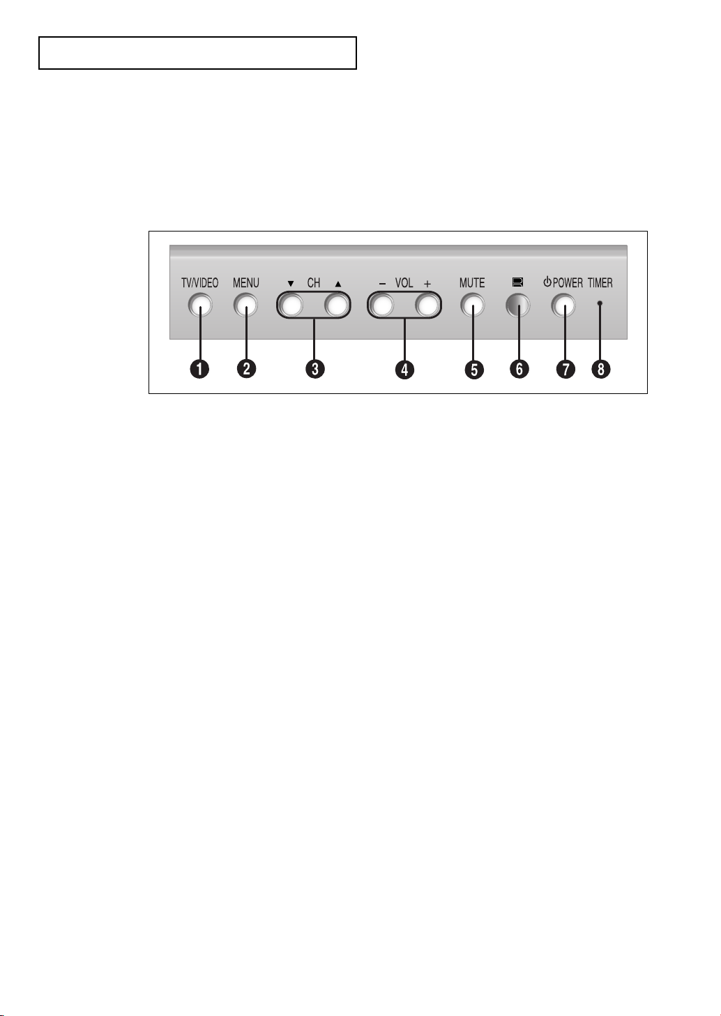
Front Panel Buttons
The buttons on the front panel control your TV’s basic features, including the on-screen
menu. To use the more advanced features, you must use the remote control.
Œ
TV/VIDEO
Press this button to display a menu of all the
available signal sources. When the menu
appears, use the CH buttons to highlight a particular source, and then press VOL+ to select it.
´
MENU
Press to see an on-screen menu of your TV's features.
ˇ
CH ▼ and CH ▲
Press to change channels. Also press to highlight
various items on the on-screen menu.
¨
VOL – , +
Press to increase or decrease the volume. Also
used to select items on the on-screen menu.
Ø
Remote Control Sensor
Aim the remote control towards this spot on the
TV.
∏
POWER
Press to turn the TV on and off.
”
TIMER indicator
When the TV is turned on, the TIMER indicator
blinks ten times. This indicator illuminates when
the TIMER mode is set to the “On” position after
setting the clock and either the On timer or Off
timer, with the remote control. Even if the power
is turned off, this indicator stays lit. (Clock must
be set before using this function.)
ˆ
MUTE
Press to temporarily cut off the sound.
1.2 CHAPTER ONE: YOUR NEW TV
Page 9
Y
OUR NEW TV
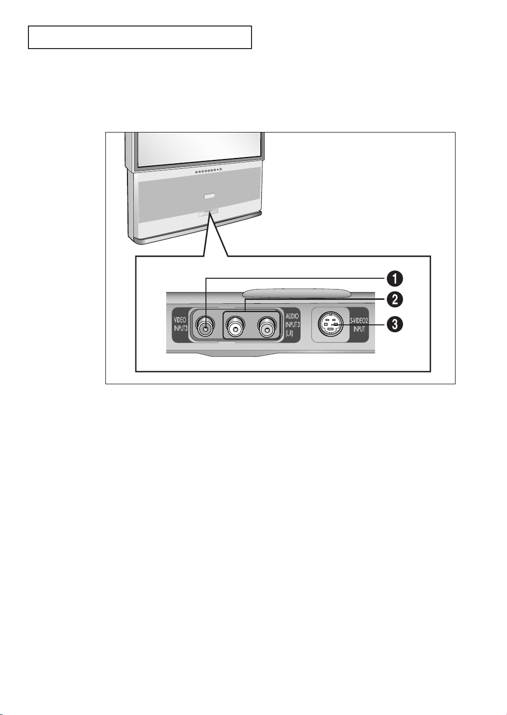
Front Panel Jacks
You can use the front panel jacks to connect an A/V component that is used only
occasionally, such as a camcorder or video game. (For information on connecting
equipment, see pages 2.1 – 2.7.)
Œ
AUDIO IN jacks
Used to connect the audio
signals from a camcorder or video game.
´
VIDEO IN jack
Used to connect a video signal from a camcorder or a video game.
ˇ
SUPER VIDEO INPUT jack
Used to connect an S-Video signal from a camcorder or a video game.
CHAPTER ONE: YOUR NEW TV 1.3
Page 10

YOUR
NEW TV
Rear Panel Jacks
Use the rear panel jacks to connect an A/V component that will be connected
continuously, such as a VCR or a laserdisc player.
Because there are two sets of input jacks, you can connect two different A/V
components (i.e., a VCR and a laserdisc, 2 VCRs, etc.)
For more information on connecting equipment, see pages 2.1 – 2.7.
Œ
VHF/UHF
Connect to an antenna or to a cable TV system.
´
WIRELESS HEADPHONES
Connect a pair of wireless headphones here
(optional)
ˇ
SUPER VIDEO INPUT
S-Video signal from an S-VHS VCR or laserdisc
player.
¨
VIDEO INPUTS
Video signals from VCRs, laserdisc players and
similar devices (Two sets are available: Video1
and Video2).
ˆ
AUDIO INPUTS
Audio signals from VCRs, laserdisc players and
similar devices.
1.4 CHAPTER ONE: YOUR NEW TV
Ø
AUDIO-VIDEO
MONITOR OUTPUTS
These audio-video signals are identical to
A/V signals being displayed on the big screen.
(Typically used as the input signals for a recording VCR.)
Note: The monitor out does not operate in DVD
mode.
∏
DVD INPUT
Connect video from a DVD player.
”
DVD AUDIO INPUT
Connect to the audio output jacks of a DVD player.
Page 11
YOUR
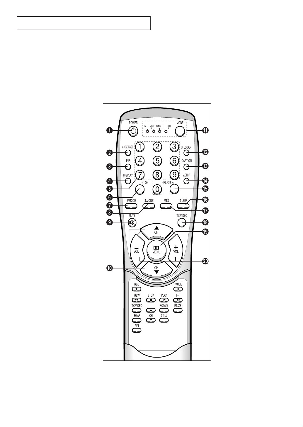
Remote Control
You can use the remote control up to about 23 feet from the TV. When using the remote,
always point it directly at the TV.
You can also use your remote control to operate your VCR and cable box. See page 4.1
for details.
Œ
POWER
Turns the TV on and off.
´
ADD/ERASE
Press to add or erase channels in
the TV’s memory.
ˇ
PIP
Activates picture in picture.
¨
DISPLAY
Press to display the current channel and the audio-video
settings.
ˆ
Number buttons
Press to select channels directly
on the TV.
Ø
+100
Press to select channels over 100.
For example, to select
channel 121, press “+100,” then
press “2” and “1.”
∏
P.MODE
Adjust the TV picture by
selecting one of the preset
factory settings (or select your
personal, customized picture
settings).
”
S.MODE
Adjust the TV sound by selecting
one of the preset factory settings
(or select your personal,
customized sound settings).
’
MUTE
Press to temporarily cut off
the sound.
˝
CH▲ and CH▼
(Channel Up/Down)
Press CH▲ or CH▼ to change
channels. (Also used to highlight
selections on the on-screen
menus.)
NEW TV
Ô
MODE
Selects a target device to be controlled by the Samsung remote
control (i.e., TV, VCR,
Cable box, or DVD).
CH.SCAN
Press to memorize (scan) the
available channels.
Ò
CAPTION
Controls the caption decoder.
Ú
V.CHIP
Press to set up and activate the
parental locks.
Æ
PRE-CH
Tunes to the previous channel.
ı
SLEEP
Press to select a preset time interval for automatic shutoff.
˜
MTS (Multichannel
Television Stereo)
Press to choose stereo, mono or
Separate Audio Program (SAP
broadcast).
¯
TV/VIDEO
Press to display all of the
available video sources (i.e.,
Antenna/cable, VCR, DVD,
Video1~3 and S-Video 1~2).
˘
MENU
Displays the main on-screen
menu.
¿
VOL
-, VOL +
Press increase or decrease the
volume. (Also used to make selections on the on-screen menus.)
CHAPTER ONE: YOUR NEW TV 1.5
Page 12
Y
OUR NEW TV
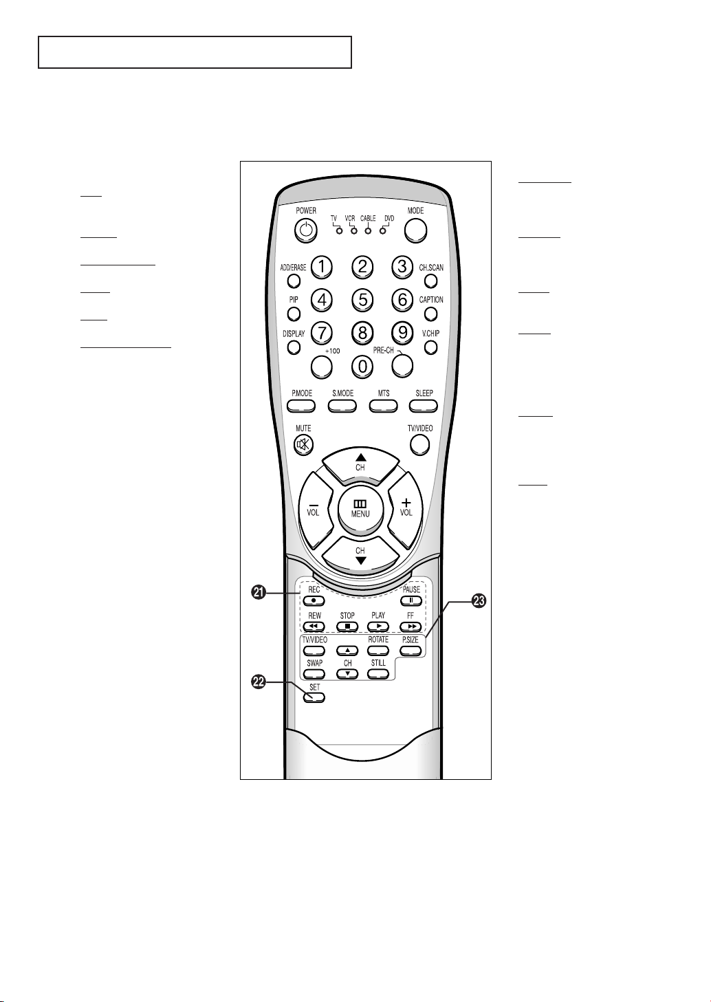
Remote Control (continued)
¸
VCR controls
REC
Press to begin recording. (Note:
A VCR must be connected.)
P
AUSE
Press to pause the tape.
REW (Rewind)
Press to rewind a tape.
STOP
Press to stop a tape in your VCR.
PLAY
Press to play the tape.
FF (Fast Forward)
Press to fast forward a tape.
˛
SET
Used during set up of this
Samsung remote control, so that
it will work compatibly with other
devices (VCR, cable box, etc.)
◊
PIP Controls
TV/VIDEO
Press to select one of the
available signal sources for the
PIP window.
ROT
ATE
Press to move the PIP window to
any of the four corners of the TV
screen.
P
.SIZE
Press to make the PIP window
larger or smaller.
SWAP
Exchanges the video
signal that is currently
displayed on the main
screen with the signal
in the PIP window.
PIP CH
Displays the available channels
in sequence. (These buttons
change channels in the
PIP window only).
STILL
Press to stop the action during a
particular scene. Press again to
resume normal video.
1.6 CHAPTER ONE: YOUR NEW TV
Page 13
2
Chapter Two
I
NSTALLATION
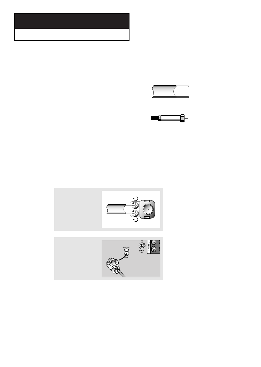
Connecting VHF and UHF Antennas
If your antenna has a set of leads that
look like this, see “Antennas with
300-ohm Flat Twin Leads,” below.
If your antenna has one lead that looks
like this, see “Antennas with 75-ohm
Round Leads,” on page 2.2.
If you have two antennas, see “Separate
VHF and UHF Antennas,” on page 2.2.
Antennas with 300-ohm Flat Twin Leads
If you are using an off-air antenna (such as a roof antenna or “rabbit ears”) that has
300-ohm twin flat leads, follow the directions below.
1
Place the wires from the
twin leads under the
screws on the 300-75
ohm adaptor (not supplied). Use a screwdriver to tighten the screws.
2
Plug the adaptor into the
VHF/UHF terminal on the
bottom of the back
panel.
CHAPTER TWO: INSTALLATION 2.1
Page 14

INSTALLATION
Antennas with 75-ohm Round Leads
1
Plug the antenna lead
into the VHF/UHF
terminal on the bottom
of the back panel.
Separate VHF and UHF Antennas
If you have two separate antennas for your TV (one VHF and one UHF), you must
combine the two antenna signals before connecting the antennas to the TV. This
procedure requires a an optional combiner-adaptor (available at most electronics shops).
1
Connect both antenna
leads to the combiner.
UHF
VHF
2
Plug the combiner into
the VHF/UHF terminal
on the bottom of the
rear panel.
Connecting Cable TV
To connect to a cable TV system, follow the instructions below.
Cable without a Cable Box
▼
1
Plug the incoming cable
into the VHF/UHF
antenna terminal on
back of the TV.
cable-ready, you do not need a
cable box to view unscrambled cable
channels.
Because this TV is
2.2 CHAPTER TWO: INSTALLATION
Page 15

INSTALLATION
Connecting to a Cable Box that Descrambles All Channels
▼
1
Find the cable that is
connected to the
ANTENNA OUT terminal
on your cable box.
This terminal might be labeled
“ANT OUT,” “VHF OUT,” or simply,
“OUT.”
2
Connect the other end
of this cable to the
VHF/UHF antenna
terminal on the back of
the TV.
Connecting to a Cable Box that Descrambles Some Channels
If your cable box descrambles only some channels (such as premium channels), follow the
instructions below. You will need a two-way splitter, an RF (A/B) switch, and four lengths of
coaxial cable. (These items are available at most electronics stores.)
▼
1
Find and disconnect the
cable that is connected
to the ANTENNA IN
terminal on your
cable box.
This terminal might be labeled
“ANT IN,” “VHF IN,” or simply,
“IN.”
2
Connect this cable to a
two-way splitter.
3
Connect a coaxial cable
between an OUTPUT
terminal on the splitter
and the IN terminal on
the cable box.
CHAPTER TWO: INSTALLATION 2.3
Page 16

INSTALLATION
4
Connect a coaxial cable
between the ANTENNA
OUT terminal on the
cable box and the B–IN
terminal on the A/B
switch.
5
Connect another cable
between the other OUT
terminal on the splitter
and the A–IN terminal
on the RF (A/B) switch.
Incoming
Cable
Incoming
Cable
Splitter
Splitter
IN CABLE OUT
Cable Box
IN CABLE OUT
Cable Box
RF (A/B)
A
B
RF (A/B)
Switch
A
B
Switch
6
Connect the last coaxial
cable between the OUT
terminal on the RF (A/B)
switch and the VHF/UHF
terminal on the rear of
the TV.
Incoming
Cable
Splitter
IN CABLE OUT
Cable Box
A
B
RF (A/B)
Switch
75
VHF/UHF
TV Rear
After you’ve made this connection, set the A/B switch to the “A” position for normal viewing.
Set the A/B switch to the “B” position to view scrambled channels. (When you set the A/B
switch to “B,” you will need to tune your TV to the cable box’s output channel, which is usually channel 3 or 4.)
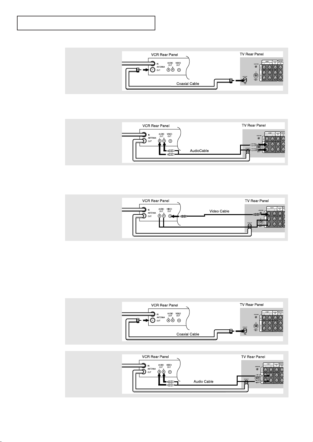
Connecting a VCR
These instructions assume that you have already connected your TV to an antenna or a cable
TV system (according to the instructions on pages 2.1-2.3). Skip step 1 if you have not yet
connected to an antenna or a cable system.
1
Unplug the cable or
antenna from the back
of the TV.
2
Connect the cable or
antenna to the
ANTENNA IN terminal
on the back of the VCR.
2.4 CHAPTER TWO: INSTALLATION
Incoming
Cable or
Antenna
VCR Rear Panel
AUDIO
IN
OUT
ANTENNA
LR
OUT
VIDEO
OUT
Page 17
INSTALLATION
3
Connect a coaxial cable
between the ANTENNA
OUT terminal on the
VCR and the antenna
terminal on the TV.
A coaxial cable is usually included with a VCR. (If not, check your local electronics
store).
4
Connect a set of audio
cables between the
AUDIO OUT jacks on the
VCR and the AUDIO
jacks on the TV.
If you have a “mono” (non-stereo) VCR, use the Y-connector to hook up to the left and
right audio input jacks of the TV. If your VCR is stereo, you must connect two cables.
5
Connect a video cable
between the VIDEO OUT
jack on the VCR and the
VIDEO jack on the TV.
Follow the instructions in “Viewing a VCR or Camcorder Tape” to view your VCR tape.
Connecting an S-VHS VCR
Your Samsung TV can be connected to an S-Video signal from an S-VHS VCR. (This
connection delivers a better picture as compared to a standard VHS VCR.)
1
To begin, follow steps
1–3 in the previous
section to connect the
antenna or cable to your
VCR and your TV.
2
Connect a set of audio
cables between the
AUDIO OUT jacks on the
VCR and the 2 AUDIO
INPUT jacks on the TV.
Make sure the jacks you are using are underneath the number “2.”
CHAPTER TWO: INSTALLATION 2.5
Page 18

INSTALLATION
3
Connect an S-video
cable between the
S-VIDEO OUT jack on
the VCR and the
S-VIDEO INPUT
jack on the TV.
An S-video cable is usually included with an S-VHS VCR. (If not, check your local
electronics store.)
Connecting a Second VCR to Record from the TV
Your TV can send out signals of its picture and sound to be recorded by a second VCR.
To do this, connect your second VCR as follows:
1
Connect a set of audio
cables between the
AUDIO OUT jacks on the
TV and the AUDIO IN
jacks on the VCR.
(The VCR input jacks might be either on the front or on back of the VCR.)
2
Connect a video cable
between the VIDEO OUT
jack on the TV and the
VIDEO IN jack on the
VCR.
Refer to your VCR’s instructions for more information about how to record using this kind
of connection.
2.6 CHAPTER TWO: INSTALLATION
Page 19

INSTALLATION
Connecting a Camcorder
The front/side panel jacks on your TV make it easy to connect a camcorder to your TV. They
allow you to view the camcorder tapes without using a VCR. (Also see “Viewing a VCR or
Camcorder Tape” on page 3.14)
1
Locate the A/V output
jacks on the camcorder.
They are usually found
on the side or back of
the camcorder.
Camcorder
Output Jacks
OUTPUT
VIDEOAUDIO
2
Connect an audio cable
between the AUDIO
OUTPUT jack on the
camcorder and the
AUDIO terminals on the
side of the TV.
3
Connect a video cable
between the VIDEO
OUTPUT jack on the
camcorder and the
VIDEO terminal on the
side of the TV.
The audio-video cables shown here are usually included with a Camcorder. (If not, check
your local electronics store.) If your camcorder is stereo, you need to connect a set of two
cables.
CHAPTER TWO: INSTALLATION 2.7
Page 20

INSTALLATION
Installing Batteries in the Remote Control
1
Slide the cover out completely.
▼
2
Install two AAA size
batteries.
3
Replace the cover.
“
–” ends of the batteries with the
diagram inside the compartment.
▼
them in a cool, dry place if you won’t
be using the remote control for a
long time.
Make sure to match the “
Remove the batteries and store
+” and
The remote control can be used up
to about 23 feet from the TV.
(Assuming typical TV usage, the
Batteries last for about one year.)
2.8 CHAPTER TWO: INSTALLATION
Page 21

Chapter Three
O
PERATION
Turning the TV On and Off
Press POWER.
You can also use the POWER button on the front panel.
Adjusting Basic Convergence
If the color appears spread out or “smeared” on the screen, the convergence probably
needs alignment. Be sure to use the remote control for the convergence adjustments.
(The Convergence Adjustment cannot be made by using the control buttons on
the front panel.)
First steps:
1
Press MENU.
Press CH ▼ twice to
highlight the Setup icon
(starts blinking).
2
Press VOL +.
Press CH ▼ three times to
highlight “Convergence”
(the letters change to
blue color).
3
Press VOL + : The
“Manual Convergence”
screen will appear, and
the word “Red” will be
highlighted.
SET UP
Channel set up
ANT / CATV
Time
Convergence
Language
Caption
V-chip
Move ExitEnt.
Channel set up
ANT / CATV
Time
Convergence
Language
Caption
V-chip
Move Ent. Menu
Manual convergence
Red
Blue
ANT
English
±
SET UP
ANT
English
±
SET UP
Move Ent. Menu
±
continued...
CHAPTER THREE: OPERATION 3.1
Page 22

OPERATION
Adjust Red Convergence
4
While “Red” is highlighted (letters are
blue color), press the VOL+ button:
A crosshair pattern will appear on the
screen. If either a vertical or a
horizontal red line is visible, then the
convergence needs alignment.
5
If a horizontal red line is
visible, use CH▲ and CH▼ buttons
to move the line so that it is superimposed on the horizontal centerline (i.e., make a single horizontal
line that is as white as possible.)
6
If a vertical red line is visible, use
the VOL + and VOL - buttons to
move the line so that it is superimposed on vertical-center line (i.e.,
make a single vertical line that is as
white as possible.)
Please, use remote control
R
Please, use remote control
R
Please, use remote control
R
Up/Down
±
L/R
Menu
Up/Down
±
L/R
Menu
Up/Down
±
L/R
Menu
7
At this point, the Red convergence
is correctly adjusted. Press MENU,
then press the CH▼ button once to
highlight the word “Blue.”
Adjust Blue Convergence
9
After the blue convergence is
correctly adjusted, press MENU four times to exit all the menus.
3.2 CHAPTER THREE:OPERATION
8
While the word “Blue” is highlighted, press the VOL+ button to adjust
the blue convergence. When the
crosshair pattern appears, use
CH▲ and CH▼ and VOL + - to
converge the blue line (same
procedure as in steps 1~7, above).
Manual convergence
Red
Blue
Move Ent. Menu
Please, use remote control
B
SET UP
±
Up/Down
±
L/R
Menu
Page 23

OPERATION
Move Ent. Exit
±
VIDEO
Settings
Contrast
Brightness
Sharpness
Color
Tint
Custom
ANT 4
Video : Custom
Audio : Custom
MTS : Mono
Signal : Mono
Viewing the Menus and On-Screen Displays
Viewing the Menus
▼
The on-screen menus disappear
1
With the power on,
press MENU.
The main menu appears
on the screen. Its left
side has four icons:
Video, Audio, Setup, and
PIP.
2
Use the CH▲ and CH▼ buttons to highlight one of the 4 icons
(the icons blink when highlighted). Then press VOL+ to access
the icon’s sub-menu.
from the screen after about thirty
seconds.
▼
You can also use the MENU,
CHANNEL, and VOLUME buttons
on the control panel of the TV to
make selections.
3
Press MENU to exit.
Viewing the Display
The display identifies the current channel and the status
of certain audio-video settings.
1
Press the DISPLAY
on the remote control.
The TV will display the
channel, the type of
audio, and the status of
certain video and audio
settings.
(“MFT” indicates a
channel has been
manually fine tuned.)
▼
The on-screen displays
disappear after about ten seconds.
CHAPTER THREE:OPERATION 3.3
Page 24

OPERATION
Move Sel. Menu
±
SET UP
Channel set up
ANT / CATV
Time
Convergence
Language
Caption
V-chip
ANT
English
Move ExitEnt.
±
SET UP
Channel set up
ANT / CATV
Time
Convergence
Language
Caption
V-chip
ANT
English
Selecting a Menu Language
1
Press MENU to display
the menu.
Press CH ▼ two times to
select “SET UP.”
2
Press VOL + to display
the “SET UP” menu.
Press CH ▼ four times
to highlight Language.
3
Press VOL + to select the appropriate language: English,
Spanish, or French.
4
Press MENU twice to exit.
3.4 CHAPTER THREE: TV OPERATION
Page 25

OPERATION
Move ExitEnt.
±
SET UP
Channel set up
ANT / CATV
Time
Convergence
Language
Caption
V-chip
ANT
English
Move Sel. Menu
±
SET UP
Channel set up
ANT / CATV
Time
Convergence
Language
Caption
V-chip
ANT
English
Move Sel. Menu
±
SET UP
Channel set up
ANT / CATV
Time
Convergence
Language
Caption
V-chip
STD
English
Memorizing the Channels
Your TV can memorize and store all of the available channels for both “off-air” (antenna)
and cable channels. After the available channels are memorized, use the CH ▲ and
CH ▼ buttons to scan through the channels. This eliminates the need to change channels
by entering the channel digits. There are three steps for memorizing channels: selecting a
broadcast source, memorizing the channels (automatic) and adding and deleting channels
(manual).
Selecting the Video Signal-source
Before your television can begin memorizing the available channels, you must specify the
type of signal source that is connected to the TV (i.e., an antenna or a cable system).
1
Press MENU to
display the menu.
2
Press CH ▼ two times to
highlight “SET UP.”
3
Press VOL +.
The setup sub-menu will
appear. Press CH ▼ to
highlight ANT/CATV.
4
Repeatedly press VOL + to cycle
through these choices:
ANT (antenna), STD, HRC or IRC (all
cable TV).
Note: STD, HRC and IRC identify various types of cable TV systems.
Contact your local cable company to identify the type of cable system
that exists in your particular area.
At this point the signal source has been selected. Proceed to “Storing
Channels in Memory” (next page).
CHAPTER THREE: TV OPERATION 3.5
Page 26

OPERATION
Move Ent. Menu
±
SET UP
Auto program
Fine tune
LNA
00
Off
Move Ent. Menu
±
SET UP
Channel set up
ANT / CATV
Time
Convergence
Language
Caption
V-chip
ANT
English
Auto program
ANT 4
ANT 11
+: Stop
Storing Channels in Memory (Automatic Method)
1
First, select the correct
signal source (ANT, STD,
HRC, IRC). See steps 1~4
on previous page.
Press MENU, then press
CH ▼ twice to highlight
“SET UP.”
Press VOL + to access
the SETUP sub-menu.
“Channel set up” will be
highlighted.
2
Press VOL + while
“Channel set up” is highlighted. A new sub-menu
will appear, and “Auto
program” will be
highlighted.
3.6 CHAPTER THREE: TV OPERATION
3
Press VOL + again.
The TV will begin
memorizing all of the
available channels.
4
After all the available
channels are stored, the
Auto program menu
reappears. Press Menu
three times to exit.
Note: Channel auto program does not function when the
V-chip is active.
▼
The TV automatically cycles
through all of the available channels
and stores them in memory. This
takes about one to two minutes.
Press VOL+ at any time to interrupt
the memorization process and return
to the Setup menu.
Page 27

OPERATION
Adding and Erasing Channels (Manual Method)
1
Use the number buttons to directly select the channel that
will be added or erased.
2
Press ADD/ERASE:
Repeatedly pressing this button will alternate between
“Channel added” and “Channel erased.”
Press MENU to exit.
You can view any channel (including an erased channel) by using the number
buttons on the remote control.
Changing Channels
Using the Channel Buttons
1
Press the CH ▲ or CH ▼ button to change
channels.
When you press CH ▲ or CH ▼, the TV changes channels in sequence. You will
see all the channels that the TV has memorized. (The TV must have memorized
at least three channels.) You will not see channels that were either erased or not
memorized.
Directly Accessing Channels
Use the number buttons to quickly tune to any channel.
1
Press the number
buttons to go directly to a channel. For example, to select
channel 27, press “2,” then “7.” The TV will change channels
when you press the
second number.
When you use the number buttons, you can directly select channels that were
either erased or not memorized.
To select a channel over 100, press the +100 button. (For channel 122, press
“+100,” then “2,” then “2.”)
To change to single-digit channels (0–9) faster, press “0” before the
single digit. (For channel “4,” press “0,” then “4.”)
CHAPTER THREE: TV OPERATION 3.7
Page 28

OPERATION
Move Ent. Menu
±
SET UP
Channel set up
ANT / CATV
Time
Convergence
Language
Caption
V-chip
ANT
English
SET UP
Move Adj. Menu
±
Time
Clock
On time
Off time
Sleep Off
On time volume
-- : -- AM
-- : -- AM Off
-- : -- AM Off
10
SET UP
Adj. Move Menu
±
Time
Clock
On time
Off time
Sleep Off
On time volume
6 : 00
AM
-- : -- AM Off
-- : -- AM Off
10
SET UP
Adj. Move Menu
±
Time
Clock
On time
Off time
Sleep Off
On time volume
6 : 30
AM
-- : -- AM Off
-- : -- AM Off
10
Setting the Clock
1
Press the MENU button
to display the on-screen
menu.
2
Press CH ▼ twice to
highlight “SET UP.”
Press VOL +.
3
Press CH ▼ twice to
highlight Time menu.
Press VOL + : The Time
menu will appear on the
screen, and “Clock” will
be highlighted (blue
color).
4
Press VOL + again (the
hours digits will start
blinking). Press CH ▼
repeatedly until the
correct hour appears.
After the hour is
entered, press VOL +
(at this point the minutes
digits will start blinking).
5
Press the CH ▲ or CH ▼
button to select the
correct minutes.
After selecting the
correct minutes, press
VOL +.
6
Press MENU three times
to exit.
▼
When selecting the hours, be sure
to select the proper time of day (AM
or PM).
You can change the hours by pressing
CH ▲ or CH ▼ repeatedly (or by
holding down either of these buttons).
▼
The time will appear every time
you press DISPLAY.
3.8 CHAPTER THREE: TV OPERATION
Page 29

OPERATION
Adjusting the Volume
1
Press VOL + or – VOL to increase or decrease the volume.
Using Mute
At any time, you can temporarily cut off the sound using the Mute button.
1
Press MUTE and the sound cuts off.
The word “Mute” will appear in the lower-left corner of the
screen.
2
To turn mute off, press MUTE again, or simply press either
the VOL – or VOL + button.
CHAPTER THREE: TV OPERATION 3.9
Page 30

OPERATION
Move Ent. Exit
±
VIDEO
Settings
Contrast
Brightness
Sharpness
Color
Tint
Custom
Move Sel. Menu
±
VIDEO
Settings
Contrast
Brightness
Sharpness
Color
Tint
Custom
Adj. Menu
±
Brightness 50
Move Adj. Menu
±
VIDEO
Settings
Contrast
Brightness
Sharpness
Color
Tint
Custom
Customizing the Picture
You can use the on-screen menus to change the contrast, brightness, tint, color, and
sharpness according to personal preference. (Alternatively, you can use one of the
“automatic” settings. See next page.)
1
Press MENU to access
the main menu.
The VIDEO icon will be
highlighted (starts blinking).
2
Press
VOL – or VOL +
repeatedly, until the word
“Custom” is highlighted.
(When Custom is highlighted, the words
“Contrast,” “Brightness,”
“Sharpness,” “Color,” and
“Tint” will appear on the
screen.)
3
Press CH ▼ or CH ▲
button to highlight a
particular item.
4
Press VOL – or VOL + to
increase or decrease
the value of a particular
item. For example, if you
select “Brightness,”
pressing VOL + increases it.
Press MENU twice to
3.10 CHAPTER THREE: TV OPERATION
exit.
▼
After adjusting an item, the gauge
will automatically disappear (after
about 5 seconds).
Page 31

OPERATION
Move Sel. Menu
±
VIDEO
Settings
Contrast
Brightness
Sharpness
Color
Tint
Custom
Sel. Menu
±
VIDEO
Settings Mild
Using Automatic Picture Settings
Your Samsung TV has two automatic picture settings (“Standard” and “Mild”) that are
preset at the factory. You can activate either Standard or Mild by pressing P.Mode (or by
making a selection from the menu). Or, you can select “Custom” which automatically
recalls your personalized picture settings.
1
Press MENU to
display the menu. Video
icon will be highlighted
(blinking).
Press VOL + to display
the VIDEO menu.
2
Press VOL - or VOL + to
select the “Standard,”
“Mild,” or “Custom”
picture setting.
3
Alternate method:
Simply press the P.MODE button on the remote control to
select one of the standard picture settings.
• Choose Standard for the standard factory settings.
• Choose Mild (“Mild Contrast”) when viewing the TV in low light, or when
playing video games.
• Choose Custom if you want to adjust the settings accordings to personal
preference (see “Customizing the Picture, page 3.10).
CHAPTER THREE: TV OPERATION 3.11
Page 32

OPERATION
Move Sel. Menu
±
AUDIO
Settings
Treble
Bass
Balance
MTS
Headphone
Custom
Mono
Main
Move Adj. Menu
±
AUDIO
Settings
Treble
Bass
Balance
MTS
Headphone
Custom
Mono
Main
Move Ent. Exit
±
AUDIO
Settings
Treble
Bass
Balance
MTS
Headphone
Custom
Mono
Main
Adj. Menu
±
Bass 50
Customizing the Sound
You can use the on-screen menus to adjust the bass, treble, and balance according to
individual preference. (Alternatively, you can use one of the “automatic” settings. See
next page.)
1
Press MENU to display
the menu.
Press CH ▼ to highlight the AUDIO icon
(starts blinking).
2
Press VOL - or VOL +
repeatedly, until the
word “Custom” is highlighted. (When Custom
is highlighted, the words
“Bass,” “Treble,” and
“Balance” will appear
on the screen.
3
Press the CH ▲ or CH ▼
buttons to highlight a
particular item to be
changed.
4
Press VOL – or VOL + to
increase or decrease the
value of a particular item.
For example, if you select
“Bass,” pressing VOL +
increases it.
Press MENU twice
to exit.
3.12 CHAPTER THREE: TV OPERATION
▼
When you are finished adjusting
an item, wait about 10 seconds. The
gauge will disappear and the Audio
menu will return.
Page 33

Move Sel. Menu
±
AUDIO
Settings
MTS
Headphone
Music
Mono
Main
OPERATION
Move Ent. Exit
±
AUDIO
Settings
Treble
Bass
Balance
MTS
Headphone
Custom
Mono
Main
Using Automatic Sound Settings
Your TV has four automatic sound settings (“Standard,” “Music,” “Speech,” and “Movie”)
that are preset at the factory. You can activate any of them by pressing the S.MODE
button (or by making a selection from the on-screen menu). Or, you can select “Custom,”
which automatically recalls your personalized sound settings.
1
Press MENU to display
the menu.
Press CH▼ once to
highlight the AUDIO
menu.
2
Press VOL - or VOL +
repeatedly to select the
“Standard,” “Music,”
“Speech,” “Movie” or
“Custom” audio settings.
3
Alternate method:
Simply press the S.MODE button on the remote control to
select one of the standard sound settings.
• Choose Standard for the standard factory settings.
• Choose Music when watching music videos or concerts.
• Choose Speech when watching a show that is mostly dialogue (i.e., news).
• Choose Movies when watching movies.
• Choose Custom to recall your personalized settings.
CHAPTER THREE: TV OPERATION 3.13
Page 34

OPERATION
Select
Video 1
Video 2
Video 3
S-Video 1
S-Video 2
DVD
Video jack
Video 1 (rear panel)
Video 2 (rear panel)
Video 3 (front panel)
S-Video 1(rear panel)
S-Video 2 (front panel)
DVD-rear
Audio jack
Audio 1 "L+R"
Audio 2 "L+R"
Audio 3 "L+R"
Audio 2 "L+R"
Audio 3 "L+R"
DVD Audio "L+R"
Viewing a VCR or Camcorder Tape
You must select the appropriate mode in order to view the VCR or
Camcorder signal on the TV.
1
Make sure that the remote control is controlling the TV set.
(Press the MODE button and make sure that the “TV” LED is
illuminated.)
2
Press TV/VIDEO on the remote control, and the following onscreen menu will appear:
TV/Video Menu
ANT/CATV
Video1
Video2
Video3
S-Video1
S-Video2
DVD
When you press the TV/Video button, the on-screen
display identifies all the active video sources (and their
corresponding input jacks):
3.14 CHAPTER THREE: TV OPERATION
3
Use the CH▲ or CH▼
button to highlight a
particular signal source,
and then press VOL+ to
activate it.
Press TV/VIDEO to exit.
ANT 4
ANT/CATV
Video 1 Connected
Video 2 Connected
Video 3 Connected
S-Video 1 Not connected
S-Video 2 Not connected
DVD Not connected
Move Ent. TV/Video Exit
±
Page 35

Chapter Four
S
PECIAL FEATURES
Customizing Your Remote Control
Your Samsung TV comes equipped with a “universal” remote control. In addition to
controlling the TV, the universal remote can also operate a VCR, DVD and a cable box
(even if your VCR and cable box are made by manufacturers other than Samsung).
Note: The remote control might not be compatible with DVD Player, VCR, Cable box and others
manufactured by another company.
Setting Up Your Remote Control to Operate Your VCR
1
Turn off your VCR.
2
Press the MODE button and make sure that the VCR LED is
illuminated.
POWER
▼
The remote control has four
“modes”: “TV,” “VCR”, “CABLE”
and “DVD.” Press the “MODE” button to switch the remote control to
the “VCR” mode.
3
On your Samsung remote control, press SET.
4
Enter 3 digits of the VCR code listed on the next page for your
brand of VCR.
code, even if the first digit is a “0.”
If more than one code listed, try the
first one.
5
Press POWER on the remote control. Your VCR should turn
on. If your VCR turns on, your remote control is now set correctly.
6
Once your remote control is set up, press the MODE button
any time you want to use the remote to operate your VCR.
✓ Set the DVD mode using the same methods as above.
▼
Make sure you enter 3 digits of the
▼
If your VCR does not turn on,
repeat steps 2, 3, and 4, but try one
of the other codes listed for the
brand of your particular VCR.
If no other codes are listed, try each
code, 000 through 089.
▼
When your remote control is in
the “VCR” mode, the volume buttons
still control your TV’s volume.
When your remote is in the “TV”
mode, the VCR control buttons (PLAY,
PAUSE, etc.) will still operate your
VCR.
CHAPTER FOUR:SPECIAL FEATURES 4.1
Page 36

VCR Codes
Admiral
Aiwa
Akai
Audio Dynamics
Bell & Howell
Broksonic
Candle
Cannon
Citizen
Colortyme
Craig
Curtis-Mathes
Daewoo
DBX
Dimensia
Dynatech
Electrohome
Emerson
Fisher
Funai
GE
Go Video
Harman Kardon
Hitachi
Instant Replay
JC Penney
JCL
JVC
Kenwood
KLH
LG
Lloyd
Logik
LXI
Magnavox
Marantz
Marta
MEI
Memorex
MGA
Midland
Minota
Mitsubishi
Montgomery ward
MTC
Multitech
NEC
Optimus
Panasonic
Pentax
Pentex Reserch+
Philco
Philips
Pioneer
Portland
ProScan
Quartz
Quasar
Radio Shack/Realist
RCA
Samsung
Sansui
Sanyo
Scott
Sears
Sharp
Shintom
Signature
Sony
Sylvania
Symphonic
Tandy
Tashiko
Tatung
Teac
Technics
Ternika
TMK
Toshiba
Totevision
Unitech
Vector Research
Victor
Video Concepts
Videosonic
Wards
Yamaha
Zenith
006, 079
015
017, 022, 023, 027, 030
014, 016
002
010
007, 009, 013, 045, 046, 052
008, 053
007, 009, 013, 045, 046, 052
014
007, 012
000, 007, 008, 014,
015, 046, 053, 064, 067
013, 045, 076
014, 016
000
015
027
008, 009, 010, 013, 015, 020, 023, 027,
034, 041, 042, 047, 049, 057, 062, 065, 067, 068, 070
002, 012, 018, 019, 043, 048, 058
015
000, 007, 008, 032, 053
007
014
005, 015, 035, 036
008
002, 005, 007, 008, 014,
016, 030, 035, 051, 053
008, 002, 014, 016, 030, 046
002, 014, 088, 089
002, 014, 016, 030, 046
073
009, 014, 046, 060
015
031
015
008, 029, 053, 056
002, 008, 014, 016,
029, 030, 046, 061
009
008
008, 009, 012, 015
027
032
005, 035
005, 027, 035, 040
006
007, 015
007, 015, 031, 032
002, 014, 016, 030, 046, 061, 064
006
008, 053, 075, 077
005, 035
046
008, 029, 053, 056
008, 029
005, 016, 033, 050
044, 045, 052
000
002
008, 053
002, 006, 008,
009, 012, 015, 019, 027, 045, 053
000, 005, 007, 008, 028,
035, 037, 054, 069
007, 013, 022, 032, 042, 077
016
002, 012
013, 041, 049, 068
002, 005, 009, 012, 018,
019, 035, 043, 048
006, 027, 039, 045
017, 026, 031, 055
015
017, 026, 038
008, 015, 029, 053, 056
015
002, 015
009
030
015, 030, 069
008
008, 009, 015, 021
067
005, 013, 019, 048, 049
007, 009
007
014, 016
016
014, 016
007
005, 006, 007, 008, 009,
012, 013, 015, 027, 031, 035
002, 014, 016, 030, 046
011, 017, 026, 079
Philips
Proscan
RCA
Toshiba
Panasonic
Sony
Samsung
001
002
002
003
004
008
000
SPECIAL FEATURES
DVD Codes
4.2 CHAPTER FOUR:SPECIAL FEATURES
Setting Up Your Remote Control to Operate Your Cable Box
1
Turn off your cable
box.
Note: The remote control might not be compatible with DVD
Player, VCR, Cable box and others manufactured by another
company.
POWER
continued...
Page 37

SPECIAL FEATURES
Anvision
Cablestar
Eagle
Eastern Int.
General Instrument
GI
Hamlin
Hitachi
Jerroid
Macom
Magnavox
NSC
Oak
Osk Sigma
Panasonic
Philips
Pioneer
Randtek
RCA
Regal
Regency
SA
Samsung
Signature
Sprucer
Starcom
Stargate 2000
Sylvania
Texscan
Tocom
Unika
Universal
Viewster
Warner Amex
Zenith
007, 008
007, 008
007, 008
002
046
004, 005, 015, 023, 024,
025, 030, 036, 067, 068, 069
003, 012, 013, 034, 048
037, 043, 046
004, 005, 015, 023, 024,
025, 030, 036, 046, 062, 065
037, 043
007, 008, 019, 021,
026, 028, 029, 032, 033, 040, 041
009
016, 038
016
003, 027, 039, 061,
073, 074
007, 008, 019, 021, 026,
028, 029, 032, 033, 040, 041
018, 020, 044, 074, 077
007, 008
000, 027, 066
003, 012, 013
002, 033
070, 071, 072
044, 003, 022, 063, 064
046
027
046
058
011, 059
011, 059
017, 021, 049, 050, 055, 073
031, 032, 041
051, 052
007, 008, 019, 021, 026,
028, 029, 032, 033, 040, 041
044
014, 042, 057, 061,
075, 076
2
Press the MODE button and make sure that the CABLE LED is
illuminated.
3
On your Samsung remote control, press SET.
4
Enter 3 digits of the cable box code listed below for your
brand of cable box.
5
Press POWER. Your cable box should turn on. If your cable
box turns on, your remote control is now “set up” correctly.
6
Once your remote control is set up, press the MODE button
any time you want to use the remote to operate your cable
box.
▼
The remote control has four
“modes”: “TV,” “VCR,” “CABLE”
and “DVD.”
Press the “MODE” button to switch
the remote control to the “Cable”
mode.
▼
Make sure you enter 3 digits of
the code, even if the first digit is a
“0.” (If more than one code listed,
try the first one.)
▼
If your cable box does not turn
on, repeat steps 2, 3, and 4, but try
one of the other codes listed for your
particular brand of cable box. (If no
other codes are listed, try each cable
box code, 000 through 077.)
▼
When your remote control is
in the “CABLE” mode, the volume
buttons still control your TV’s volume. Also, the VCR control buttons
(PLAY, PAUSE, etc.) will still operate
your VCR.
Cable Box
Codes
Note: The remote control might not be compatible with DVD Player, VCR, Cable box and others manufactured by another company.
CHAPTER FOUR:SPECIAL FEATURES 4.3
Page 38

SPECIAL FEATURES
Move ExitEnt.
±
SET UP
Channel set up
ANT / CATV
Time
Convergence
Language
Caption
V-chip
ANT
English
Move Ent. Menu
±
SET UP
Channel set up
ANT / CATV
Time
Convergence
Language
Caption
V-chip
ANT
English
SET UP
Adj. Move Menu
±
Time
Clock
On time
Off time
Sleep Off
On time volume
6 : 30
AM
5 : 00
AM Off
-- : -- AM Off
10
SET UP
Time
Clock
On time
Off time
Sleep Off
On time volume
6 : 30
AM
5 : 15
AM Off
-- : -- AM Off
10
Adj. Move Menu
±
Setting the On/Off Timer
1
Press MENU to display
the menu.
Press CH ▼ twice to
highlight the “SET UP”
sub-menu.
2
Press VOL + to select
the “SET UP” sub-menu.
Press CH ▼ twice to
highlight "Time."
Press VOL +.
▼
Before using the timer, you must
set the TV’s clock. (See “Setting the
Clock” on page 3.8)
When any of the timers are set, the
“Timer” LED will illuminate (front
panel of TV).
3
Press CH ▼ to select
“On time.”
Press VOL + to highlight
the “On time” hours.
(The hours digits will
start blinking.)
Press CH ▲ or CH ▼
repeatedly to select the
appropriate hours (i.e.,
the hour when the TV
will turn on.)
4
Press VOL + to highlight
the “On time” minutes.
(The minutes digits will
start blinking.)
Press CH ▲ or CH ▼ )to
select the appropriate
minutes.
4.4 CHAPTER FOUR:SPECIAL FEATURES
continued...
▼
When you set the hours, make
sure the correct time of day (AM or
PM) appears to the left of the hour.
Page 39

SPECIAL FEATURES
SET UP
Time
Clock
On time
Off time
Sleep Off
On time volume
6 : 30
AM
5 : 15
AM On
-- : -- AM Off
10
Adj. Move Menu
±
SET UP
Move Adj. Menu
±
Time
Clock
On time
Off time
Sleep Off
On time volume
6 : 30
AM
5 : 15
AM On
-- : -- AM Off
10
5
Press VOL + to
highlight “On/Off.”
Press CH ▲ (or CH ▼)
to turn the on-timer
“On.” (Repeatedly
pressing CH ▲ or
CH ▼ will alternate
between on and off.)
6
When finished, press
VOL +.
7
To set the Off time, press
CH ▼ to highlight “Off
time.”
Press VOL + and set the
hours and minutes.
(Follow the same procedure as in steps 1~6
above.)
▼
To deactivate the “On time,”
select “Off” during this step.
8
When finished setting the timer, press MENU three times to
exit.
Setting the Sleep Timer
The sleep timer automatically shuts off the TV after a preset time
(from 10 to 360 minutes).
▼
After about 5 seconds, the sleep
1
Press the SLEEP button on the remote control.
display will disappear from the
screen, and the time interval will be
set.
2
Press SLEEP repeatedly until the appropriate time interval
appears (any of the preset values from “Off” to “360”).
CHAPTER FOUR:SPECIAL FEATURES 4.5
Page 40

SPECIAL FEATURES
Move Sel. Menu
±
SET UP
Closed caption
Caption
Mode
Channels
Field
On
Caption
1
1
Move Sel. Menu
±
SET UP
Closed caption
Caption
Mode
Channels
Field
On
Caption
1
1
CC
Move ExitEnt.
±
SET UP
Channel set up
ANT / CATV
Time
Convergence
Language
Caption
V-chip
ANT
English
Move Sel. Menu
±
SET UP
Channel set up
ANT / CATV
Time
Convergence
Language
Caption
V-chip
ANT
English
Viewing Closed Captions
Your TV decodes and displays the closed captions that are broadcast with certain TV shows.
These captions are usually subtitles for the hearing impaired or foreign-language translations. All VCRs record the closed caption signal from television programs, so home-recorded
video tapes also provide closed captions. Most pre-recorded commercial video tapes provide
closed captions as well. Check for the closed caption symbol in your television schedule and
on the tape’s packaging: .
Note: The Caption feature does not work with DVD signals.
▼
Quick way to access captions
1
Press MENU to display the
menu.
Press CH ▼ two times to
select the “SET UP” menu.
Press VOL+.
menu: Simply press the Caption button on the remote control.
2
Press CH ▼ five times to
select the “Caption” menu.
4.6 CHAPTER FOUR:SPECIAL FEATURES
Press VOL+ to open the
Caption menu.
3
Press VOL+ or VOL – to turn
closed captioning on/off.
4
Press CH ▼ to
highlight “Mode.”
Press VOL – or VOL + to select
“Caption” or “Text.”
5
Depending on the particular broadcast, it might be necessary to
make changes to “Channels” and “Field”:
Use the CH ▲, CH ▼, VOL + and VOL - buttons to make the
changes. (Follow the same procedure as in steps 3~4 above.)
Press MENU three times to exit.
▼
Misspellings and unusual
characters sometimes occur during
closed caption transmissions, especially those of live events. There may be a
small delay before captions appear
when you change channels. These are
not malfunctions of the TV.
▼
In caption mode, captions
appear at the bottom of the screen,
and they usually cover only a small
portion of the picture.
In text mode, information unrelated
to the program, such as news or
weather, is displayed. Text often
covers a large portion of the screen.
▼
Different channels and fields
display different information: Field 2
carries additional information that
supplements the information in
Field 1. (For example, Channel 1
may have subtitles in English, while
Channel 2 has subtitles in Spanish.)
Page 41

SPECIAL FEATURES
Move ExitEnt.
±
SET UP
Channel set up
ANT / CATV
Time
Convergence
Language
Caption
V-chip
ANT
English
Move Sel. Menu
±
SET UP
Auto program
Fine tune
LNA
+01
Off
Fine Tuning Channels
Use fine tuning to manually adjust a particular channel for optimal reception.
1
Select the appropriate
channel.
2
Press MENU.
Press CH ▼ two times
to highlight “SET UP.”
3
Press VOL + to select
Setup menu. (Channel set
up” will be highlighted.)
Press VOL + so that “Auto
program” is highlighted.
Press CH ▼ once to
select “Fine tune.”
4
Press the VOL – and VOL + buttons to adjust the fine tuning.
5
To store the fine tuning setting in the TV’s memory, press CH ▲.
(A yellow-heart icon will appear.)
To reset the fine tuning to “00,”press CH ▼ .
▼
After you adjust the fine tuning,
the letters “MFT” will appear when
you press DISPLAY while watching
this channel.
▼
Press the MENU button to
resume normal viewing.
CHAPTER FOUR:SPECIAL FEATURES 4.7
Page 42

SPECIAL FEATURES
Move Sel. Menu
±
SET UP
Auto program
Fine tune
LNA
+01
Off
Move Sel. Menu
±
SET UP
Auto program
Fine tune
LNA
+01
On
LNA (Low Noise Amplifier)
If the TV is operating in a weak-signal area, sometimes the LNA function can improve the
reception (a low-noise preamplifier boosts the incoming signal).
1
Press MENU to display
the menu.
Press CH ▼ two times to
highlight the “SET UP”
menu.
Press VOL + to select the
Set up menu. “Channel set
up” will be highlighted.
2
Press VOL + to select
“Channel set up.”
Press CH ▼ twice to
highlight “LNA.”
3
Press VOL - or VOL + to
select LNA “on.”
Channel set up
ANT / CATV
Time
Convergence
Language
Caption
V-chip
Move ExitEnt.
±
SET UP
ANT
English
▼
Pressing VOL - or VOL + will
alternate between “On” and “Off.”
Press MENU three times
to exit.
4.8 CHAPTER FOUR:SPECIAL FEATURES
Page 43

SPECIAL FEATURES
Move Sel. Menu
±
AUDIO
Settings
Treble
Bass
Balance
MTS
Headphone
Custom
Mono
Main
Move Sel. Menu
±
AUDIO
Settings
Treble
Bass
Balance
MTS
Headphone
Custom
Main
SAP
Move Ent. Exit
±
AUDIO
Settings
Treble
Bass
Balance
MTS
Headphone
Custom
Mono
Main
Special Audio Options: MTS and Headphones
Choosing a Multi-Channel Sound (MTS) Soundtrack
Depending on the particular program being broadcast, you can listen to stereo, mono, or a
Separate Audio Program. (SAP audio is usually a foreign-language translation. Sometimes
SAP has unrelated information like news or weather.)
▼
Quick way to access the MTS
1
Press MENU to display
the menu.
Press CH▼ once to
highlight the AUDIO
menu.
menu: Just press “MTS” on the
remote control.
2
Press VOL + to select
the AUDIO menu.
Press CH▼ to
highlight “MTS”.
▼
The text at the bottom of the
3
Press VOL + repeatedly
menu tells you if the incoming
audio is stereo, SAP, or mono.
to select “Mono,”
“SAP,” or “Stereo.”
Press MENU twice to
exit
• Choose Stereo for channels that are broadcasting in stereo.
• Choose Mono for channels that are broadcasting in mono, or if you are
having difficulty receiving a stereo signal.
• Choose SAP to listen to the Separate Audio Program, which is usually a
foreign-language translation.
You can also change the MTS setting by pressing the “MTS” button on the remote
control. (When you change channels, MTS is set to “Stereo” automatically.
To listen in ‘SAP’ or ‘Mono,’ change the MTS setting.)
CHAPTER FOUR:SPECIAL FEATURES 4.9
Page 44

S
Move Sel. Menu
±
AUDIO
Settings
Treble
Bass
Balance
MTS
Headphone
Custom
Mono
Sub
PECIAL FEATURES
Using Wireless Headphones
The wireless headphone option is especially useful when simultaneously watching the
main screen and the PIP window.
▼
Note: Wireless head-
1
Connect the transmitter
cable to the Wireless
Headphone jack on the
bottom of the back
panel.
phones must be purchased
separately.
2
Turn the transmitter and
Wireless Headphones
on.
3
Adjust the volume of the
Wireless Headphones.
VOL
Setting up Wireless Headphones with Picture-in-Picture
(See page 4.11 for information about the various options for picture-in-picture.)
1
Press MENU and press
CH ▼ once to highlight
the AUDIO icon.
Press VOL+, then press
CH ▼ to highlight
“Headphone.”
2
Press VOL+ to alternate
between “Main” and
“Sub” (the sound associated with program in PIP
window). If PIP is not
active, then the “Sub”
option is not available.
4.10 CHAPTER FOUR:SPECIAL FEATURES
Press MENU twice to exit.
AUDIO
Settings
Treble
Bass
Balance
MTS
Headphone
Move Sel. Menu
Custom
Mono
Main
±
▼
Note: The “Headphone” option
is active only when the PIP window
is active.
▼
Notes: If there is an obstacle
between the transmitter and the
Wireless Headphones, the sound
may be affected. For additional
details, see your Wireless
Headphones instruction book.
Page 45

SPECIAL FEATURES
PIP
PIP Off
Sel. Menu
±
PIP
PIP
TV/Video
Swap
PIP size
ANT/CATV
Channel
On
TV
Small
ANT
ANT 4
Move Sel. Menu
±
Viewing Picture-in-Picture
You can use the PIP feature to simultaneously to watch two video sources.
Note: The PIP feature does not work with DVD signals.
Activating Picture-in-Picture
▼
Quick way to access the PIP
1
Press MENU to display
the menu.
Press CH▼ three times
to highlight the PIP menu.
Press VOL + to select the
PIP menu.
2
Press VOL + to select
PIP “On.”
menu: Simply press the PIP button
on the remote control.
▼
If you turn TV off while watching
and turn it on again, the PIP window
will disappear.
3
Press MENU twice to exit.
Note: Picture-in-Picture does not function when the V-chip is
active.
CHAPTER FOUR:SPECIAL FEATURES 4.11
Page 46

SPECIAL FEATURES
PIP
PIP
TV/Video
Swap
PIP size
ANT/CATV
Channel
On
TV
Small
ANT
ANT 4
Move Sel. Menu
±
PIP
PIP
TV/Video
Swap
PIP size
ANT/CATV
Channel
On
TV
Small
STD
STD 4
Move Sel. Menu
±
Selecting a Signal Source (Antenna or Cable) for PIP
1
Press MENU to display
the menu.
Press CH▼ four times
to select the PIP menu.
Press VOL + to select
the PIP menu.
2
Press CH▼ four times to
select “ANT/CATV.”
If an antenna is connected, the setting is “ANT.”
If a Cable TV system is
providing the signal,
press VOL + or VOL - until
the appropriate type of
cable system is is displayed (“STD,” “HRC,” or
“IRC”).
Press MENU twice to exit.
Selecting a Signal Source (External A/V) for PIP
Press TV/VIDEO repeatedly to cycle through all of the available
signal sources:
“TV,” “Video 1,” “Video 2,” “Video 3,” “S-Video 1,”and
“S-Video 2.”
Swapping the Contents of the PIP image and Main image
When you press the SWAP button:
The image in the PIP window will appear on the main
screen, and vice versa.
4.12 CHAPTER FOUR:SPECIAL FEATURES
▼
For more information about
external A/V components and signals, see “Viewing a VCR or
Camcorder Tape” on page 3.14.
If you select “TV”, the PIP image is
the same as the main image.
Page 47

SPECIAL FEATURES
Changing the PIP Channel
Press PIP CH▲ or CH▼ to change the channel that appears
in the PIP window.
Changing the Location (Rotating) the PIP Window
When you press the ROTATE button repeatedly, the PIP win-
dow moves from corner to corner on the TV screen.
Freezing the PIP Image
Press STILL to stop the action in a particular scene. Press
STILL again to resume normal video.
Changing the Size of the PIP Window
Press P.SIZE to alternate between a smaller and larger PIP
window.
Scanning the Available Channels
This procedure scans all of the available channels and then
stores them in memory.
Press CH.SCAN, and the memorized channels will appear in
sequence for 2 to 3 seconds per channel.
Press CH.SCAN again to stop the scanning process.
When CH.SCAN stops, the viewing mode will return to its
original setting.
CHAPTER FOUR:SPECIAL FEATURES 4.13
Page 48

Move Ent. Menu
±
SET UP
Channel set up
ANT / CATV
Time
Convergence
Language
Caption
V-chip
ANT
English
SET UP
V-chip
Enter pin :
SET UP
V-chip mode
V-chip lock
TV guidelines
MPAA rating
Change pin
No
SET UP
Confirm new pin
Confirm new pin
SET UP
Change pin
Enter new pin:
SPECIAL FEATURES
Using the V-Chip
The V-Chip feature automatically locks out programming that is deemed inappropriate for
children. The user must first enter a PIN (personal ID number) before any of the V-Chip
restrictions can be set up or changed.
Note : When the V-chip feature is active, the PIP and channel-auto program features do not
function.
Setting Up Your Personal ID Number (PIN)
1
Press MENU to display
the menu.
Press CH ▼ two times
to select the “SET UP”
menu.
Press VOL + .
▼
Quick way to access the V-Chip
menu: Simply press the V.CHIP
button on the remote control.
2
Press CH ▼ six times to
select the “V-chip”
menu.
Press VOL+.
The “Enter pin” screen will appear. Enter your 4-digit PIN
number. Note: The default PIN number for a new TV set is
“0-0-0-0.”
3
After entering a valid PIN
number, the “V-chip mode”
screen will appear. Press
CH ▼ three times and high-
light “Change pin.”
(Note: When a particular
field is highlighted, its color
turns BLUE.)
4
While the “Change pin”
field is selected, press
VOL +. The Change pin
screen will appear.
Choose any 4-digits for
your PIN and enter them.
As soon as the 4 digits are entered, the “Confirm pin” screen
appears. Re-enter the same 4 digits. When the Confirm
4.14 CHAPTER FOUR:SPECIAL FEATURES
screen disappears, your PIN has been memorized.
Press MENU to exit.
▼
Note: If you forget the PIN,
press the remote-control keys in the
following sequence, which resets the
pin to 0-0-0-0:
POWER OFF ➜ MUTE ➜ 8 ➜ 2 ➜
4 ➜ POWER ON.
Page 49

Move Ent. Menu
±
SET UP
Channel set up
ANT / CATV
Time
Convergence
Language
Caption
V-chip
ANT
English
Menu
SET UP
V-chip
Enter pin :
SET UP
V-chip mode
V-chip lock
TV guidelines
MPAA rating
Change pin
Yes
Move Ent Menu
±
Move Ent. Menu
±
SET UP
Channel set up
ANT / CATV
Time
Convergence
Language
Caption
V-chip
ANT
English
SPECIAL FEATURES
How to Enable/Disable the V-Chip
1
Press MENU.
Press CH ▼ two times
to select the “SET UP”
menu.
Press VOL + .
2
Press CH ▼ six times to
highlight the “V-chip”
menu.
Press VOL+ .
The “Enter pin” screen
will appear. Enter your
4-digit PIN number.
3
The “V-Chip mode” screen
will appear, and “V-Chip lock”
will be highlighted (turns blue
color).
To enable the V-Chip feature,
press VOL + so that the “VChip lock” field is YES.
(Pressing VOL + will alternate
between YES and NO.)
How to Set up Restrictions Using the “TV guidelines”
First, set up a personal identification number (PIN), and enable the V-Chip. (See previous
section.) Parental restrictions can be set up using either of two methods: The TV guidelines or the MPAA rating.
1
Press MENU to display
the menu.
Press CH ▼ two times to
highlight the “SET UP”
menu.
Press VOL + .
CHAPTER FOUR:SPECIAL FEATURES 4.15
Page 50

Menu
SET UP
V-chip
Enter pin :
SET UP
V-chip mode
V-chip lock
TV guidelines
MPAA rating
Change pin
Yes
Move Ent. Exit
±
TV GUIDELINES
TV-Y
TV-Y7
TV-G
TV-PG
TV-14
TV-MA
U
U
U
U
U
U
U
U
U
U
U
U
U
UUU
U
U
All FV V S L D
B: Blocked U: Unblocked
Young children
S
PECIAL FEATURES
2
Press CH ▼ six times to highlight the “Vchip” menu.
Press VOL+ .
The “Enter pin” screen will appear. Enter
your 4-digit PIN number.
3
The “V-chip mode” screen will appear. Press the
CH ▼ button, and highlight the field for “TV
Guidelines.” (Note: When a particular field is
highlighted, its color turns BLUE.)
4
Press VOL +. The “TV guidelines”
screen will appear. Press the CH ▲,
CH ▼ buttons to highlight one of the
six age-based categories:
TV-Y Young children
TV-Y7 Children 7 and over
-------------------------------------TV-G General audience
TV-PG Parental guidance
TV-14 Viewers 14 and over
TV-MA Mature audience
▼
Note: These categories consist of two separate groups: TV-Y
and TV-Y7 (young children
through age 7), and TV-G
through TV-MA (everybody
else). The TV-Y and TV-Y7 categories are colored green.
The restrictions for these two
groups work independently: If a
household includes very young
children as well as young adults,
the TV guidelines must be set up
separately for each age group.
(See next step.)
5
At this point, one of the TV-Ratings is highlighted (blue color).
Press the VOL + button: Depending on your existing setup, a letter “U” or “B” will start blinking.
(U= Unblocked, B= Blocked)
While the “U” or ”B” is blinking, press the CH ▲ or CH ▼ button to block or unblock the category.
Press MENU once to save the TV guidelines. A TV-Rating will be highlighted (BLUE), and no letters will blink. To exit
this screen, press MENU again. To select a different TV-Rating, press CH ▲ or CH ▼ and then repeat the process.
Note 1: The TV-Y7, TV-PG, TV-14 and TV-MA have additional options. See the next step to change
any of the following sub-ratings:
FV: Fantasy violence
D: Dialog
L: L
S: Sexual situation
V: Violence
4.16 CHAPTER FOUR:SPECIAL FEATURES
Note 2: The V-Chip will automatically block certain categories that are “more restrictive.” For example, if you block
“TV-Y” category, then TV-Y7 will automatically be blocked. Similarly, if you block the TV-G category, then all the categories in the “young adult” group will be blocked (TV-G, TV-PG, TV-14 and TV-MA). The sub-ratings (D, L, S, V) work
together similarly. (See next section.)
Page 51

Move Ent. Menu
±
SET UP
Channel set up
ANT / CATV
Time
Convergence
Language
Caption
V-chip
ANT
English
Menu
SET UP
V-chip
Enter pin :
SPECIAL FEATURES
6
How to set the FV, D, L, S and V sub-ratings.
First, highlight one of these TV-Ratings: TV-Y7, TV-PG, TV-14 or TV-MA (See Step 4, on previous page).
Next, while the TV-Rating is highlighted (BLUE), repeatedly press the VOL + button. This will cycle through the
available sub-ratings (FV,L, S, D or V).
A blinking letter (“U” or “B”) will be displayed for each sub-rating. While the “U” or “B” is blinking, press
CH ▲ or CH ▼ to change the sub-rating.
Press MENU once to save the TV guidelines. A TV-Rating will be highlighted (BLUE), and no letters will blink.
To exit this screen, press MENU again. To select a different TV-Rating, press CH ▲ or CH ▼ and then repeat
the process.
Note: The V-chip will automatically block certain categories that are “More restrictive”. For example, if you
block “L” sub-rating in TV-PG, then the “L” sub-ratings in TV-14 and TV-MA will automatically be blocked.
7
Press the MENU button three times to clear all the screens. (Or proceed to the next section, and set up additional restrictions based on the MPAA codes).
How to Set up Restrictions using the MPAA Ratings: G, PG, PG13, R, NC-17, X
The MPAA rating system uses the Motion Picture Association of America (MPAA) system,
and its main application is for movies. (Eventually, movie videocassettes will be encoded
with MPAA ratings.) When the V-Chip lock is on, the TV will automatically block any
programs that are coded with objectionable ratings (either MPAA or TV-Ratings).
1
Press MENU to display the menu.
Press CH ▼ two times to highlight
the “SET UP” menu.
Press VOL + .
2
Press CH ▼ six times to highlight
the “V-chip” menu.
Press VOL+ .
The “Enter pin” screen will appear.
Enter your 4-digit PIN number.
CHAPTER FOUR:SPECIAL FEATURES 4.17
Page 52

MPAA RATING
G
PG
PG-13
R
NC-17
X
NR
U
U
U
U
U
U
Move Ent. Menu
±
B: Blocked U: Unblocked
SET UP
V-chip mode
V-chip lock
TV guidelines
MPAA rating
Change pin
Yes
Move Ent. Exit
±
S
MPAA RATING
G
PG
PG-13
R
NC-17
X
NR
U
U
U
U
U
U
Move Ent. Menu
±
B: Blocked U: Unblocked
PECIAL FEATURES
3
The “V-chip mode” screen will appear.
Press the CH ▼ button twice, and highlight
“MPAA rating.”
4
While “MPAA rating” is highlighted,
press the VOL + button. The “MPAA rating” screen will appear.
5
Repeatedly press the CH ▼
button to highlight a
particular MPAA category.
(When a category is
highlighted, its color changes
to blue.) Pressing the CH ▼
button will cycle through the
MPAA categories:
G General audience (no restrictions).
PG Parental guidance suggested.
PG-13 PG-13 (Parents strongly cautioned).
R R (Restricted. Children under 17 should
be accompanied by an adult).
NC-17 No children under age 17.
X X (Adults only).
NR Not rated.
While a particular category is highlighted, press VOL + to activate it.
A blinking letter (“U” or “B”) will be displayed. Press CH ▲ or CH ▼ to select “U” or”B”.
Press MENU three times to save the settings and to clear all screens.
Note: The V-Chip will automatically block any category that is “more restrictive.” For example, if you
block the “PG-13” category, then “R,” “NC-17,” and “X” will automatically be blocked also.
How to Reset the TV after the V-Chip Blocks a Channel (“Emergency Escape”)
If the TV is tuned to a restricted channel, the V-Chip will block it. The screen will go blank and the following
message will appear: “Excessive rating.”
To resume normal viewing, tune to a different channel using the number buttons. Under certain conditions
(depending on the rating of the local TV programs) the V-Chip might lock out all the channels. In this case, use
the V-Chip button for an “emergency escape”:
Press the V-chip button on the remote control. Enter your PIN number, and press VOL + to temporarily disable
the V-Chip Lock.
4.18 CHAPTER FOUR:SPECIAL FEATURES
Page 53

Chapter Five
T
ROUBLESHOOTING
If the TV seems to have a problem, first try this list of possible problems and solutions. If
none of these troubleshooting tips apply, then call your nearest service center.
Identifying Problems
Problem Possible Solution
Poor picture Try another channel.
Poor sound quality. Try another channel.
No picture or sound. Try another channel.
No color, wrong colors or tints. Make sure the program is broadcast in color.
Picture rolls vertically. Adjust the antenna.
The TV operates erratically. Unplug the TV for 30 seconds, then try
Your remote control does not Press the “MODE” button to put your remote
operate your TV. control in the “TV” mode.
The TV won’t turn on. Make sure the wall outlet is working.
Adjust the antenna.
Check all wire connections.
Adjust the antenna.
Press the TV/VIDEO button.
Make sure the TV is plugged in.
Check the antenna connections.
Adjust the picture settings.
Check all wire connections.
operating it again.
Note: If you watch a still image for a long time, some burning images may be seen
on the screen.
CHAPTER FIVE: TROUBLESHOOTING 5.1
Page 54

APPENDIX
Cleaning and Maintaining Your TV
With proper care, your TV unit will give you many years of service. Please follow these
guidelines to get the maximum performance from your TV.
Placement
• Do not place the TV near extremely hot, cold, humid or dusty places.
• Do not place the TV near appliances with electric motors that create magnetic fields,
such as vacuum cleaners.
• Keep the ventilation openings clear; do not place the TV on a soft surface, such as
cloth or paper.
• Place the TV in a vertical position only.
Liquids
• Do not handle liquids near or on the TV. Liquids that spill into it can cause serious
damage.
Cabinet
• Never open the cabinet or touch the parts inside.
•Wipe your TV with a clean, dry cloth. Never use water, cleaning fluids, wax, or
chemicals.
• Do not put heavy objects on top of the cabinet.
Temperature
• If your TV is suddenly moved from a cold to a warm place, unplug the power cord,
and allow at least two hours for moisture that may have formed inside the unit to dry
completely.
A.1 APPENDIX
Using Your TV in Another Country
If you plan to take your TV with you to a foreign country, please be aware of the different
television systems that are in use around the world. A TV designed for one system may
not work properly with another system due to differences in the TV channel frequencies
Specifications
Model
Voltage
Frequency of Operation
Power Consumption
Dimension
Weight
ST-54T6 : 1161 x 605 x 1400mm ; 45.70 x 23.82 x 55.12 inchs
ST-62T6 : 1319 x 705 x 1529mm ; 51.93 x 27.76 x 60.20 inchs
ST-54T6 / ST-62T6
100 ~ 240 V ca
50/60Hz (Mexico: 60Hz)
230 Watts / 230 Watts
ST-54T6 : 70 Kg ; 154.32 lbs
ST-62T6 : 88 Kg ; 194.00 lbs
 Loading...