

Page 1

Standalone Biometric
Access Controller
user manual
SSA-S3010
SSA-S3011
SSA-S3020
SSA-S3021
SSA-S3040
SSA-S3041
imagine the possibilities
Thank you for purchasing this Samsung product.
To receive more complete service,
please visit our website.
www.samsungsecurity.com
Page 2
2_ safety information
safety information
CAUTION
RISK OF ELECTRIC SHOCK.
DO NOT OPEN
CAUTION: TO REDUCE THE RISK OF ELECTRIC SHOCK, DO NOT REMOVE COVER (OR BACK) NO USER SERVICEABLE
PARTS INSIDE. REFER SERVICING TO QUALIFIED SERVICE PERSONNEL.
This symbol indicates that dangerous voltage consisting a risk of electric shock is
present within this unit.
This exclamation point symbol is intended to alert the user to the presence of
important operating and maintenance (servicing) instructions in the literature
accompanying the appliance.
WARNING
To reduce the risk of fi re or electric shock, do not expose this appliance to rain or moisture.
WARNING
Be sure to use only the standard adapter that is specifi ed in the specifi cation sheet.
Using any other adapter could cause fi re, electrical shock, or damage to the product.
Incorrectly connecting the power supply or replacing battery may cause explosion, fi re, electric shock, or damage to
the product.
Do not connect multiple controllers to a single adapter. Exceeding the capacity may cause abnormal heat generation or fi re.
Securely plug the power cord into the power receptacle. Insecure connection may cause fi re.
When installing the controller, fasten it securely and fi rmly. The fall of controller may cause personal injury.
Do not place conductive objects (e.g. screwdrivers, coins, metal parts, etc.) or containers fi lled with water on top of the
controller. Doing so may cause personal injury due to fi re, electric shock, or falling objects.
Do not install the unit in humid, dusty, or sooty locations. Doing so may cause fi re or electric shock.
If any unusual smells or smoke come from the unit, stop using the product. In such case, immediately disconnect the
power source and contact the service center. Continued use in such a condition may cause fi re or electric shock.
If this product fails to operate normally, contact the nearest service center. Never disassemble or modify this product in
any way. (SAMSUNG is not liable for problems caused by unauthorized modifi cations or attempted repair.)
. When cleaning, do not spray water directly onto parts of the product. Doing so may cause fi re or electric shock.
CAUTION
Do not drop objects on the product or apply strong blows to it. Keep away from a location subject to excessive
vibration or magnetic interference.
Do not install in a location subject to high temperature (over 50°C), low temperature (below 0°C), or high humidity.
Doing so may cause fi re or electric shock.
If you want to relocate the already installed product, be sure to turn off the power and then move or reinstall it.
Remove the power plug from the outlet when there is a lighting storm. Neglecting to do so may cause fi re or damage
to the product.
Keep out of direct sunlight and heat radiation sources. It may cause fi re.
Install it in a place with good ventilation.
•
1.
2.
3.
4.
5.
6.
7.
8.
9.
10.
1.
2.
3.
4.
5.
6.
Page 3

English English _ 3
SAFETY INFORMATION
Avoid aiming the controller directly towards extremely bright objects such as sun.
Apparatus shall not be exposed to dripping or splashing and no objects fi lled with liquids, such as vases, shall be
placed on the apparatus.
The Mains plug is used as a disconnect device and shall stay readily operable at any time.
FCC Statement
Caution : Any changes or modifi cations in construction of this device which are not expressly approved by the
party responsible for compliance could void the user’s authority to operate the equipment.
This device complies with part 15 of the FCC Rules. Operation is subject to the following two conditions:
This device may not cause harmful interference, and
This device must accept any interference received, including interference that may cause undesired operation.
NOTE: This equipment has been tested and found to comply with the limits for a Class B digital device, pursuant to Part
15 of the FCC Rules. These limits are designed to provide reasonable protection against harmful interference in a
residential installation. This equipment generates, uses and can radiate radio frequency energy and, if not installed
and used in accordance with the instructions, any cause harmful interference to radio communications. However,
there is no guarantee that interference will not occur in a particular installation. If this equipment does cause harmful
interference to radio or television reception, which can be determined by turning the equipment off and on, the user
is encouraged to try to correct the interference by one or more of the following measures:
- Reorient or relocate the receiving antenna.
- Increase the separation between the equipment and receiver.
- Connect the equipment into an outlet on a circuit different from that to which the receiver is connected.
- Consult the dealer or an experienced radio/TV technician for help.
7.
8.
9.
1)
2)
Read these instructions.
Keep these instructions.
Heed all warnings.
Follow all instructions.
Do not use this apparatus near water.
Clean only with dry cloth.
Do not block any ventilation openings. Install in accordance with the manufacturer’s instructions.
Do not install near any heat sources such as radiators, heat registers, or other apparatus (including amplifi ers) that
produce heat.
Do not defeat the safety purpose of the polarized or grounding-type plug. A polarized plug has two blades with one
wider than the other. A grounding type plug has two blades and a third grounding prong. The wide blade or the third
prong is provided for your safety. If the provided plug does not fi t into your outlet, consult an electrician for
replacement of the obsolete outlet.
Protect the power cord from being walked on or pinched particularly at plugs, convenience receptacles, and the
point where they exit from the apparatus.
Only use attachments/accessories specifi ed by the manufacturer.
Use only with cart, stand, tripod, bracket, or table specifi ed by the manufacturer, or sold with
the apparatus.
Unplug this apparatus when a card is used. Use caution when moving the cart/ apparatus
combination to avoid injury from tip-over.
Refer all servicing to qualifi ed service personnel. Servicing is required when the apparatus has been damaged in any
way, such as powersupply cord or plug is damaged, liquid has been spilled or objects have fallen into the apparatus,
the apparatus has been exposed to rain or moisture, does not operate normally, or has been dropped.
1.
2.
3.
4.
5.
6.
7.
8.
9.
10.
11.
12.
13.
14.
IMPORTANT SAFETY INSTRUCTIONS
Page 4

4_ contents
contents
PRODUCT INTRODUCTION
7
7 Features
9 What’s included
10 At a glance
12 Cable Color Scheme
13 Cable Selection
INSTALLATION AND EXTERNAL
CONNECTION
14
14 Installing the rear template
15 Connecting the termination resistor and
diode
15 Bypass Diode Connection
16 Earth-grounding the communication cables
17 I/O Connection
19 External Reader Connection
20 Communication Line Connection
INITIALIZATION
23
23 Initializing the system
24 To access the master mode
24 Registering a master ID
26 Name Display
27 User Count Setup
27 Language Setup
28 Date/Time Setup
28 Communication Address Setup
29 Baud Rate Setup
29 Factory Defaults
READER MODE SETUP
30
30 Reader #1 Mode
30 READER #2 Mode
31 READER #1 Key Input
31 READER #2 Key Input
32 Dual Fingerprint Mode
33 Adaptive Mode
33 Identifi cation Mode
Page 5

English English _ 5
CONTENTS
USER MANAGEMENT
34
34 Registering ID in Quick mode
35 Registering the ID
37 To delete ID
38 Viewing the ID list
38 To check the number of registered IDs
39 To remove all registered IDs
39 To check the number of registered
fi ngerprints
40 To remove the master IDs
40 Duress Mode
41 Door Open Alarm Time Setup
41 Arm/Disarm
42 Two Men Operation Mode
42 To check the number of events
43 To remove all events
43 To remove the time schedule
I/O TIME SETUP
44
44 Exit Button Output
44 Door Contact Sensor Setup
45 Auxiliary Input #1 Setup
45 Auxiliary Input #2 Setup
46 Tamper Alarm Output Setup
46 Cut Off Output Setup
47 Duress Mode Output Setup
47 ARM/DISARM Output Setup
48 Door Open Timeout Setup
48 Output Setup for Level IDs Accessing
READER #1
50 READER #1 Error Output Setup
51 Output Setup for Level IDs Accessing
READER #2
52 READER #2 Error Output Setup
ADVANCED SETUP
54
54 Time Unit Setup
54 Output Time Schedule+ID
55 AntiPassBack Mode
55 Time Schedule Setup
56 Holiday Setup
57 Holiday Code Setup
58 Reader Mode Time Schedule
59 Voice Message Time Schedule
59 Output Time Schedule Setup
60 Input Time Schedule Setup
60 Input Cut Off Check Setup
Page 6

6_ contents
contents
TROUBLESHOOTING
77
77 TroubleShooting
PRODUCT SPECIFICATIONS
79
79 Product Specifi cations
OTHER INFORMATION
69
69 Menu Structure
75 Default Settings
ADDITIONAL FEATURES
61
61 Event Memory Setup
61 ID Display
62 WIEGAND Output Setup
62 Voice Volume Setup
63 One Time Read
63 Version Check
64 Input Test
64 Output Test
65 LCD Test
65 Keypad Test
66 READER Test
66 Memory Test
67 Communication Test
67 Fingerprint Module Version Check
68 Input Type Setup
Page 7

English English _ 7
PRODUCT INTRODUCTION
FEATURES
State-of-the-art Access Controller
This product is a state-of-the-art access controller that is optimal for time and attendance management, and
provides 4 input ports and 2 2Form-C relay outputs along with 2 TTL output ports, RS-232/RS-485 and TCP/IP
ports to meet the high-level security system requirements and various customer needs.
With its simple manipulation and the highest security system, this product enables you to register up to 1000
persons’ fi ngerprints (2000 fi ngerprints for SSA-S302X and 4000 for SSA-S304X, depending on the model), and
save up to 20,000 IDs (10,000 for events) or up to 20,000 events (10,000 for IDs). All events can be transferred to
the host PC before being saved to the database, and output in formats of PDF, TIF or text fi le using the PC
applications for time and attendance management purposes.
This product consists of: a built-in fi ngerprint recognition module, a proximity card reader with 26 bit Wiegand(SSAS30X1: 34 bit Wiegand), and a 24-key keypad (10 numeric keys, 2 control keys and 12 function keys) for a wide
range of applications. With this, you can obtain access with any combination of your fi ngerprint, proximity card/PIN,
and password. This product is featured by the Exit button, Motion Detector, Door Contact sensor and 4 external
input ports connected to the exit alarm system preventing unauthorized access.
It also has 2 relay outputs that can control the door lock and alarm relay.
In the mean time, the graphics LCD panel supports multilingual display, enabling it operated around the world
beyond the language barrier. The dual tamper switch triggers an alert if the product is forcibly disassembled.
All system settings can be confi gured using the front keypad or through the Windows-based software. This product
works as a standalone system and is designed to operate via the network.
Standalone Operation
SSA-S30XX is connected to the external card reader, which is used to control one entrance. It determines to allow
access by reading data from the internal or external card reader, and controls the open/close of the door relay and
other output settings.
On an external signal (from a sensor or Exit button) reception, the device (relay) corresponding to the signal starts
operating.
This product has an independent control system, assuring a normal operation regardless of problems on other
systems and, not affecting them in a reversed situation.
Computer-based Management
All records of authorized or unauthorized accesses and any external signal will be saved in the internal memory. You can
download such data onto your computer according to the specifi ed communications protocol. With the downloaded
data, you can store, process, create a report based on your query (access and alert details, etc) on the connected
computer.
Keypad Registration
Even if SSA-S30XX is not connected to the host PC, you can use the built-in keypad and LCD module to register or
delete the card or confi gure necessary settings independently.
Time Scheduling
SSA-S30XX is featured by so-called time schedule, which allows you to instruct it to perform a specifi c operation for a
specifi c period of time. You can set a total of 10 time schedule codes, each of which can be assigned to each user.
Each time schedule code has a total of 8 different time zones including Monday through Sunday (7 time zones) plus
one holiday, each of which can be divided in up to 5 different time intervals, indicating you can program different time
codes.
You can also create time schedule codes to manage separate I/Os. If a time schedule code is assigned to an input
device, for instance, that device will stay active only for the time specifi ed. Each time schedule code is linked to the
holiday schedule, which is void only to the holiday time code of the time schedule. (refer to “Time Scheduling” on pages
55 to 56)
product introduction
Page 8

8_ product introduction
product introduction
External I/O Pins
SSA-S30XX has 4 input pins and 4 output pins installed(2 relay and 2 TTL outputs) The input pins can receive signals
from the Exit button and the Door Contact sensor, while the two relays can be connected to the Door Lock and the
alarm device. You can specify the output time for these output pins. (Refer to “I/O Wiring” on pages 17 to 18)
Holiday Scheduling
In total, 10 holiday schedule codes are available for SSA-S30XX models, and each holiday schedule code can be
confi gured for up to 100 holidays except Sundays. Each holiday code can be linked to the time schedule code.
You can set all holidays to holiday schedule codes, and holiday schedule code is based on the holiday time zone for
the time scheduling. (Refer to “Holiday Scheduling” on page 56)
Forced Door Open Alarm
You can set the Forced Door Open Alarm to activate when the door is opened by force.
For its application, you must have installed the door contact sensor and properly set the door contact time and output
settings for the alarm device. The Forced Door Open Alarm lasts until the alarm event is terminated. (Refer to “Door
Contact Sensor” on page 44)
ANTIPASSBACK
A door has two card readers installed: one for the entrance, and the other for the exit, so anyone who enters should
recognize his/her card on the reader at the entrance time before he can exit normally. If a person does not go under
the card recognition process and just follows another person’s way inside the door, the person is not allowed to exit
when he/she recognizes the access card on exit card reader, and the antipassback error (APB error) occurs which
will be saved into the internal memory. And you can confi gure to output a signal through a specifi c pin when such an
error occurs. (Refer to “Antipassback Error Output Setup” at pages 50 and 53.)
Arm/Disarm
As long as the device is in Arm mode, the reader ports are all frozen so that no one can get access to the door and
any input from the corresponding external pin will not be processed. In this mode, SSA-S30XX transmits a specifi c
signal to the connected security devices so that they responds properly. (Refer to “Arm/Disarm” on page 41)
Door Open Timeout Alarm
The Door Open Timeout Alarm notifi es the administrator of the fact with an alarm if a door stays open after the normal
service time. The Door Open Timeout Alarm lasts until the door is closed.
(Refer to “Door Open Timeout Setup” on page 48)
Duress Alarm
This is used in a situation where you should open the door inevitably by a robber insisting to do so. Entering the twodigit duress alarm password with pressing the
ENT
button and recognizing the registered card (or card number)
opens the door, while this forcibly unarmed situation will be notifi ed to the PC application with an alarm event. (Refer
to “Duress Mode” on page 40)
Two Men Operation Mode
In this mode, SSA-S30XX permits a certain person (visitor) to enter or exit only when accompanied by a special user
(administrator). Both the visitor and the administrator should be authorized before they can get access. (Refer to
“Registering the ID card” on page 35)
4 Levels of Individual Door Opening Time Setting
You can use this function to set 4 different door opening time points. (Refer to “Output Setup for Level IDs Accessing
Reader” at pages 48 and 51.)
Name Display
SSA-S30XX can display the name of a person when the person is authorized to get access. (Refer to “Name Display”
on page 26)
Page 9
English English _ 9
PRODUCT INTRODUCTION
WHAT’S INCLUDED
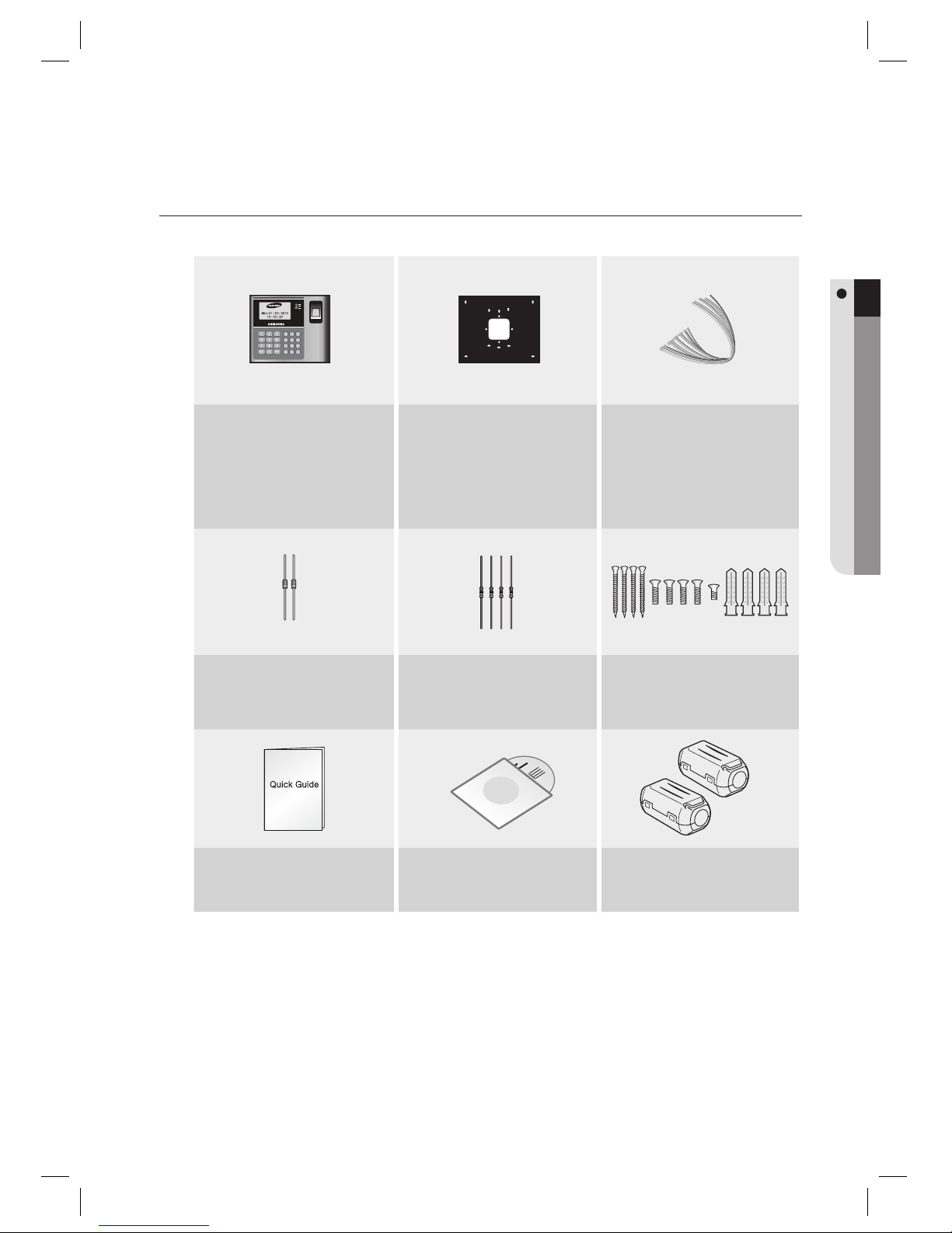
Check if the following items are included in the product package.
Main Unit Wall Mount
CABLE:
2PIN Connector (X 1)
3PIN Connector (X 1)
4PIN Connector (X 1)
5PIN Connector (X 1)
6PIN Connector (X 1)
8PIN Connector (X 1)
Diode (X 2)
(UF4004, 1N4001~4007)
Resistor (X 4)
(2.2kΩ, 1/4W)
3.5 X 40mm screws (X 4)
3.5 X 12mm screws (X 4)
3 X 8mm screws (X 1)
6 X 30mm Plastic Anchor (X 4)
xGn
Quick Guide CD Manual Ferrite Cores X 2
Page 10
10_ product introduction
product introduction
AT A GLANCE
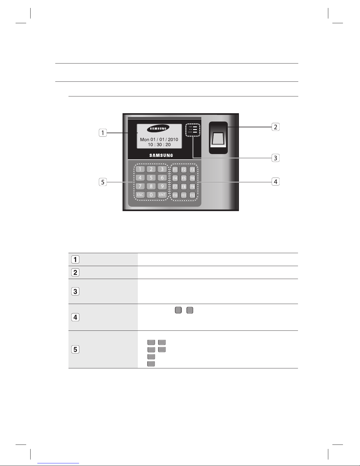
Front Panel
LCD
This module displays the operation status of the product.
Fingerprint Scanner
Fingerprint scanner module.
System Status LED
The red indicator turns on when the product turns on.
The red indicator turns on when relay #1 becomes active.
The yellow indicator turns on when relay #2 becomes active.
Menu Buttons
12 menu buttons (
F
1
~
F12
) are available for use.
Press a menu button to enter the corresponding menu.
For the complete list of menus, refer to “Menu Structure”. (on pages 69 through 74)
Input Keys
Use these to enter numbers or navigate through the menu.
4
,6 : Left/right direction buttons
2
,8: Up/down direction buttons
ENT
: Select
ESC
: Cancel
•
•
•
•
Page 11
English English _ 11
PRODUCT INTRODUCTION
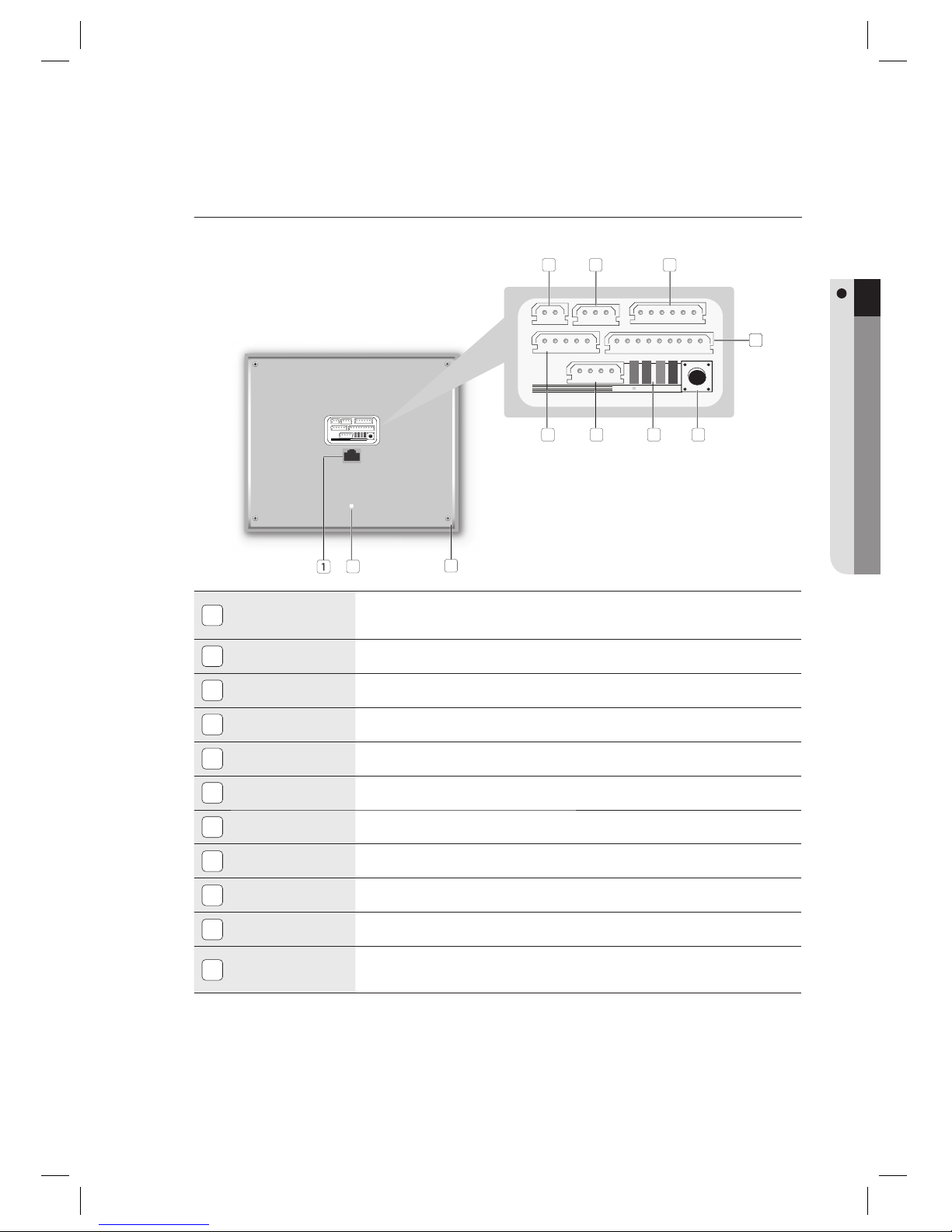
Rear Panel
1
RJ45 Connector
Used in TCP/IP communications.
Used in TCP/IP communications.
2
Tamper Switch
Tamper switch.
3
Fixing Hole
Hole for a fi xing screw.
4
2-pin Connector
Can be connected to the power cable.
5
3-pin Connector
Preliminary connector for extension.
6
6-pin Connector
Can be connected to the I/O cable.
7
8-pin Connector
Can be connected to the relay wiring cable.
8
Initialize switch
System Initialize switch.
9
LED
Communication status indicator.
10
4-pin Connector
Preliminary connector for extension.
11
5-pin Connector
Can be connected to the RS-232 and RS-485 communication cables.
2
3
4 5 6
7
89
10
67
11
Page 12
12_ product introduction
product introduction
2-PIN Connector
I/O Pins Signal Cable Color
Power (+12V) DC +12V Red
Earth-grounding GND (-) Black
3-PIN Connector
I/O Pins Signal Cable Color
RESERVED 1 Pink with White Stripes
RESERVED 2 Sky Blue with White Stripes
RESERVED 3 Black
6-PIN Connector
I/O Pins Signal Cable Color
TTL Output #1 TTL#1, WIK_D_OUT0 Orange with White Stripes
TTL Output #2 TTL#2, WIK_D_OUT1 Brown with White Stripes
Auxiliary Input #1 AUX_IN#1 Green
Auxiliary Input #2 AUX_IN#2 Green with White Stripes
Wiegand Data Input 0 WIK_D_IN0 Pink
Wiegand Data Input 1 WIK_D_IN1 Sky Blue
5-PIN Connector
I/O Pins Signal Cable Color
RS-485-RTX(+) RS-485-A(+) Yellow
RS-485-RTX(-) RS-485-B(-) Gray
RS-232-TX TXD Black with White Stripes
RS-232-RX RXD Red with White Stripes
RS-232-GND GND Black
8-PIN Connector
I/O Pins Signal Cable Color
Door RELAY(NC) NC(1) Blue with White Stripes
Door RELAY(COM) COM(1) Gray with Red Stripes
Door RELAY(NO) NO(1) White with Red Stripes
Alarm RELAY(NC) NC(2) Purple with White Stripes
Alarm RELAY(COM) COM(2) White
Alarm RELAY(NO) NO(2) Purple
Exit Button EXIT Orange
Door Contact Sensor CONTACT Yellow with Red Stripes
❖
❖
❖
❖
❖
CABLE COLOR SCHEME
Page 13
English English _ 13
PRODUCT INTRODUCTION
CABLE SELECTION
Description
Cable Type
Cable Type
1
Product Power (DC12V)
This product
Belden #9409, 18 AWG, 2 Conductor, Unshielded
Belden #9409, 18 AWG, 2 Conductor, Unshielded
2
Reader (power and data)
External reader
This
product
Belden #9512, 22 AWG, 4 Conductor, Shielded
Belden #9514, 22 AWG, 8 Conductor, Shielded
3
Door Contact Sensor
Exit Button
Sensor Input
Input This product
Belden #9512, 22 AWG, 4 Conductor, Shielded
Belden #9514, 22 AWG, 8 Conductor, Shielded
4
RS-232 Cable
Converter Host P.C.
Belden #9829, 24 AWG, 2-twisted pair, Shielded
5
RS-485 Cable
This product This product
This product Converter
Belden #9829, 24 AWG, 2-twisted pair, Shielded
4-PIN Connector
I/O Pins Signal Cable Color
RESERVED 1 Orange with Red Stripes
RESERVED 2 Orange with Black Stripes
RESERVED 3 Blue
RESERVED 4 Brown
TCP/IP RJ45 Connector
❖
❖
Page 14
14_
installation and external connection
installation and external connection
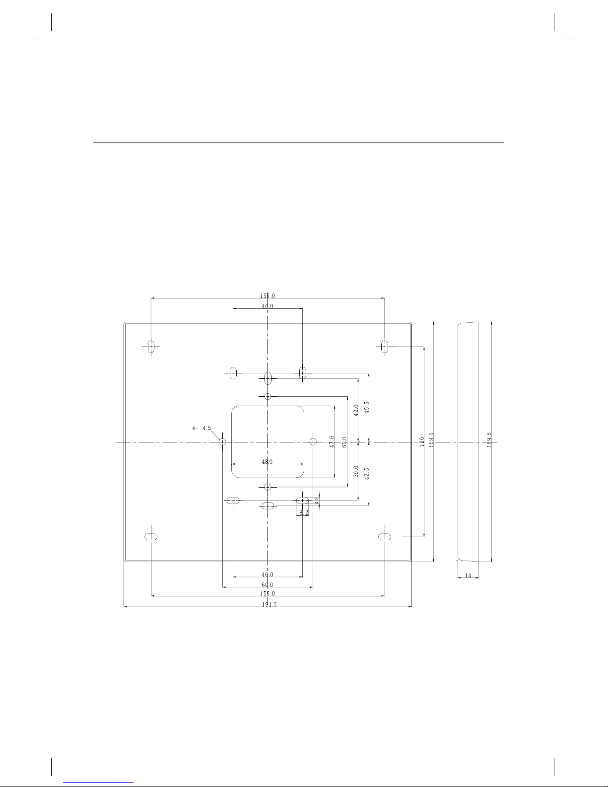
INSTALLING THE WALL MOUNT
Follow the instructions below to install the wall mount.
Place the wall mount on the installation point and mark the 4 holes for the screws. Drill at least 4 of 6-32 holes.
Drill a 1/2” hole on the center of the wall mount.
Use 4 screws to fi x the wall mount to an appropriate point.
Arrange the cables through the center hole.
Connect the cable and use one screw on the bottom of the wall mount to fi x it to the product.
Do not install the product on a metal wall. Otherwise, this will cause malfunction due to radio frequency interference
against the wall.
1.
2.
3.
4.
5.
J
Page 15
English English _ 15
INSTALLATION AND EXTERNAL CONNECTION
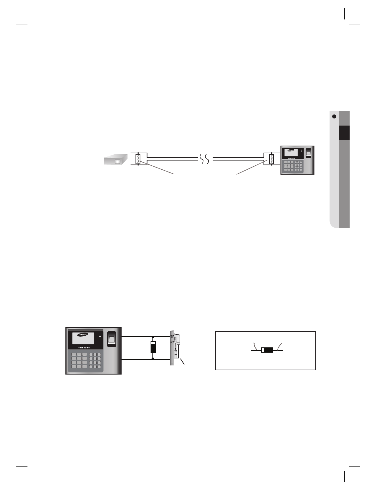
CONNECTING THE TERMINATION RESISTOR AND DIODE
A resistor is inserted for line’s impedance matching to prevent distortion and reduction in RS-422 or RS-485 long distance
data communications, which is referred to as termination resistor.
Note that termination resistors of lower than 90 are not allowed, neither more than one termination resistor is accepted
for the communications system.
BYPASS DIODE CONNECTION
If you connected an inductor (door locks or alarm device) to the output relay, there should occur a surge voltage while the
inductor was turning on and off. If you do not connect a bypass diode to the relay, the surge voltage will cause damage to
the electric circuit of the controller. To reduce this surge, it is recommended to connect a bypass diode between the
devices.
1 32
654
7 98
ESC0ENT
F1 F2 F3
F4 F5 F6
F7 F8 F9
F10 F11 F12
Mon 01 / 01 / 2010
10 : 30 : 20
183
"-.
%003
Lock/Alarm
GND(-)
DC12V
Cathode Anode
1N4004~1N4007 or equiv.
1 32
6
54
7 98
ESC0ENT
F1 F2 F3
F4 F5 F6
F7 F8 F9
F10 F11 F12
Mon 01 / 01 / 2010
10 : 30 : 20
183
"-.
%003
"
#
A
B
120Ω
120Ω
RS485/RS232
Converter
Termination Resistors
RS-485 RS-485
Page 16
16_
installation and external connection
installation and external connection
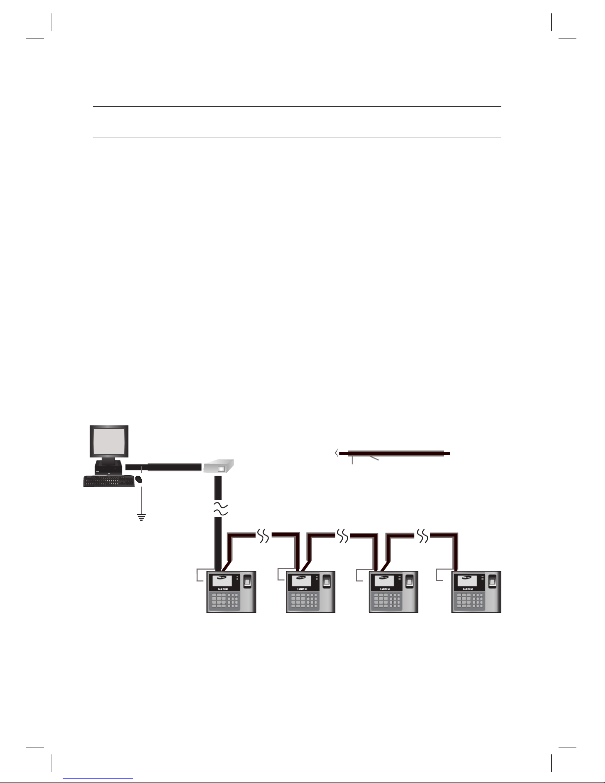
EARTH-GROUNDING THE COMMUNICATION CABLES
We recommend you to use a proper grounding system for the communication cables.
The best grounding method is to earth-ground the shield wire of the communication cable. However, earth-grounding the
communication cable isn’t that easy, apart from the cost increase.
There are three grounding points available for installation:
1. Earth Ground
2. Chassis Ground
3. Power Ground
The most important thing about the earth-grounding is not connecting both ends of the shield wire to the same grounding
system; Connecting both to the same end will cause a current fl ow through the shield wire due to the voltage level
difference between the both ends of the shield wire, and this current fl ow will introduce some noise and interference to
communications.
We recommend you connect ONLY one end of the shield wire of the communication cable to the grounding system. If you
can locate an earth grounding point nearby, connect one end of the shield wire to that point.
If you could hardly locate an earth grounding point nearby, connect one end of the shield wire to the chassis ground point.
If you could locate neither of an earth or chassis grounding point nearby, connect one end of the shield wire to the power
ground point (GND). Note that if the chassis is not properly earthed and fl oated from the ground level, then grounding
communication cable to the chassis will produce the worst communication. If this is the case, use the power grounding
point rather than the chassis grounding.
1 32
6
54
7 98
ESC0ENT
F1 F2 F3
F4 F5 F6
F7 F8 F9
F10 F11 F12
Mon 01 / 01 / 2010
10 : 30 : 20
183
"-.
%003
1 32
6
54
7 98
ESC0ENT
F1 F2 F3
F4 F5 F6
F7 F8 F9
F10 F11 F12
Mon 01 / 01 / 2010
10 : 30 : 20
183
"-.
%003
1 32
6
54
7 98
ESC0ENT
F1 F2 F3
F4 F5 F6
F7 F8 F9
F10 F11 F12
Mon 01 / 01 / 2010
10 : 30 : 20
183
"-.
%003
1 32
6
54
7 98
ESC0ENT
F1 F2 F3
F4 F5 F6
F7 F8 F9
F10 F11 F12
Mon 01 / 01 / 2010
10 : 30 : 20
183
"-.
%003
Earth Ground
or Chasis Ground
or Power Ground
HOST PC
RS-485/RS-232
Converter
Communication
Wires
Connect
ShieldWire
Open
GND GND GND GND
RS-485 RS-485 RS-485
RS-232
Page 17
English English _ 17
INSTALLATION AND EXTERNAL CONNECTION
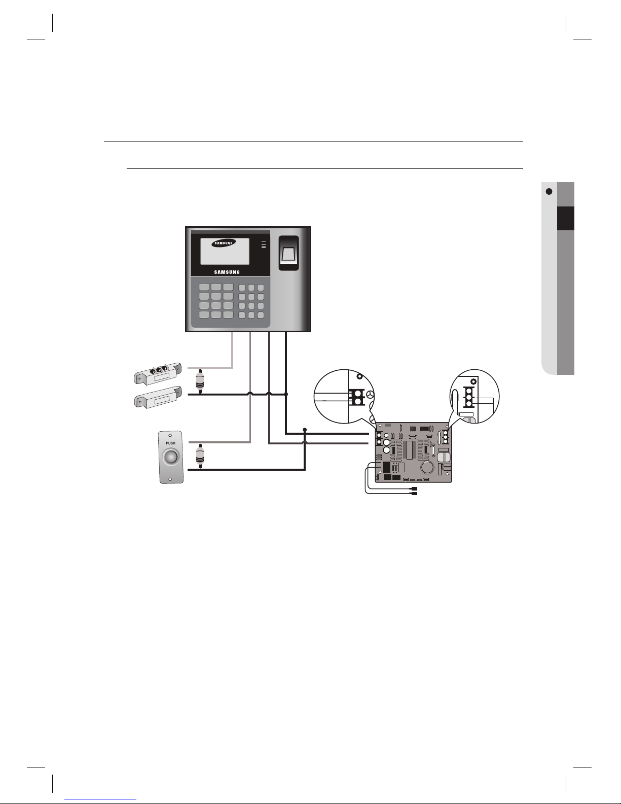
I/O CONNECTION
Input Connection
Connect the DC 12V(+) line of the power supply unit to the red line.
Connect the GND(-) line of the power supply unit to the black line.
- Exit Button Connection
Connect one end of the Exit button to the orange line.
Connect the other end of the Exit button to GND
- Door Contact Sensor Connection
Connect one end of the door contact sensor to the yellow with red stripes.
Connect the other end of the door contact sensor to GND.
-
Auxiliary Input Device Connection (auxiliary input #1 – green, auxiliary input #2 – green with white stripes)
Connect one end of the auxiliary input device to auxiliary input #1 or auxiliary input #2.
Connect the other end of the auxiliary input device to GND.
1.
2.
1.
2.
1.
2.
1.
2.
1 32
654
7 98
ESC0ENT
F1 F2 F3
F4 F5 F6
F7 F8 F9
F10 F11 F12
Mon 01 / 01 / 2010
10 : 30 : 20
183
"-.
%003
Door Contact Sensor: Yellow with the red stripe, GND
Exit Button: Orange line, GND
Connect 2.2K to check for cut-off detection
Door Contact Sensor
Exit Button
Black -
Red +
GND
DC+12v
100V-220V
FG
L
N
Power
Supply
Page 18
18_
installation and external connection
installation and external connection
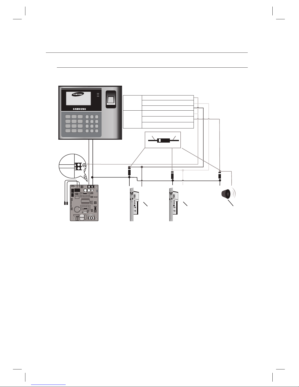
Output Connection
Connect the 8-pin connector (relay connector) of this product as follows:
- POWER FAIL SAFE: Door is opened when the power is disconnected
Connect the relay COM line (gray with red stripes for locking the door) to DC +12V.
Connect the relay NC line (blue with white stripes for locking the door) to the plus(+) line of the door lock.
Connect the minus (-) line of the door lock to GND (-).
- POWER FAIL SECURE: Door is closed when the power is disconnected
Connect the relay COM line (gray with red stripes for locking the door) to DC +12V.
Connect the relay NO line (white with red stripes for locking the door) to the plus (+) line of the door lock
Connect the minus (-) line of the door lock to GND (-).
- Alarm Connection (Alarm Relay)
Connect the relay COM (white for the alarm device) to DC +12V.
Connect the relay NO line (purple for the alarm device) to the plus (+) line of the alarm device.
Connect the minus (-) line of the alarm device to GND (-).
1.
2.
3.
1.
2.
3.
1.
2.
3.
⾄⾉⾅ ⾄⾉⾅ ⾄⾉⾅⾄⾅ ⾄⾅ ⾄⾅
1 32
654
7 98
ESC0ENT
F1 F2 F3
F4 F5 F6
F7 F8 F9
F10 F11 F12
Mon 01 / 01 / 2010
10 : 30 : 20
183
"-.
%003
Black -
Red +
GND
DC+12V
Power Supply
POWER FAIL
SAFE
POWER FAIL
SECURE
Alarm
Device
DOOR
RELAY
COM (gray with red stripes)
NO (white with red stripes)
NC (blue with white stripes)
ALARM
RELAY
COM (white)
NO (purple)
NC (purple with white stripes)
Cathode Anode
1N4004-1N4007 or equivalent
Page 19
English English _ 19
INSTALLATION AND EXTERNAL CONNECTION
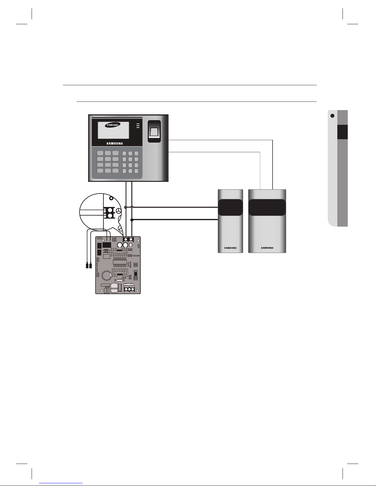
EXTERNAL READER CONNECTION
External Reader Connection
- Proximity Reader Connection
Connect the DC 12V(+) line of the power supply unit to the plus (+) line of the reader.
Connect the GND(-) line of the power supply unit to the minus(-) line of the reader
Connect the Wiegand data input line 0 of the proximity reader to the pink line
Connect the Wiegand data input line 1 of the proximity reader to the sky blue line
For a list of compliant readers (external readers), see the followings:
SSA-S30X0
- Standard 26bit Wiegand format proximity reader
- Standard 26bit Wiegand + 8bit Burst format proximity/keypad reader
SSA-S30X1
- Standard 34bit Wiegand format proximity reader
- Standard 34bit Wiegand + 8bit Burst format proximity/keypad reader
1.
2.
3.
4.
•
⾄⾇⾅
⾄⾉⾅
1 32
654
7 98
ESC0ENT
F1 F2 F3
F4 F5 F6
F7 F8 F9
F10 F11 F12
Mon 01 / 01 / 2010
10 : 30 : 20
183
"-.
%003
Black -
Red +
GND
DC+12V
Wiegand DATA0 (Pink)
Wiegand DATA1 (sky blue)
Power
Supply
Page 20
20_
installation and external connection
installation and external connection
COMMUNICATION LINE CONNECTION
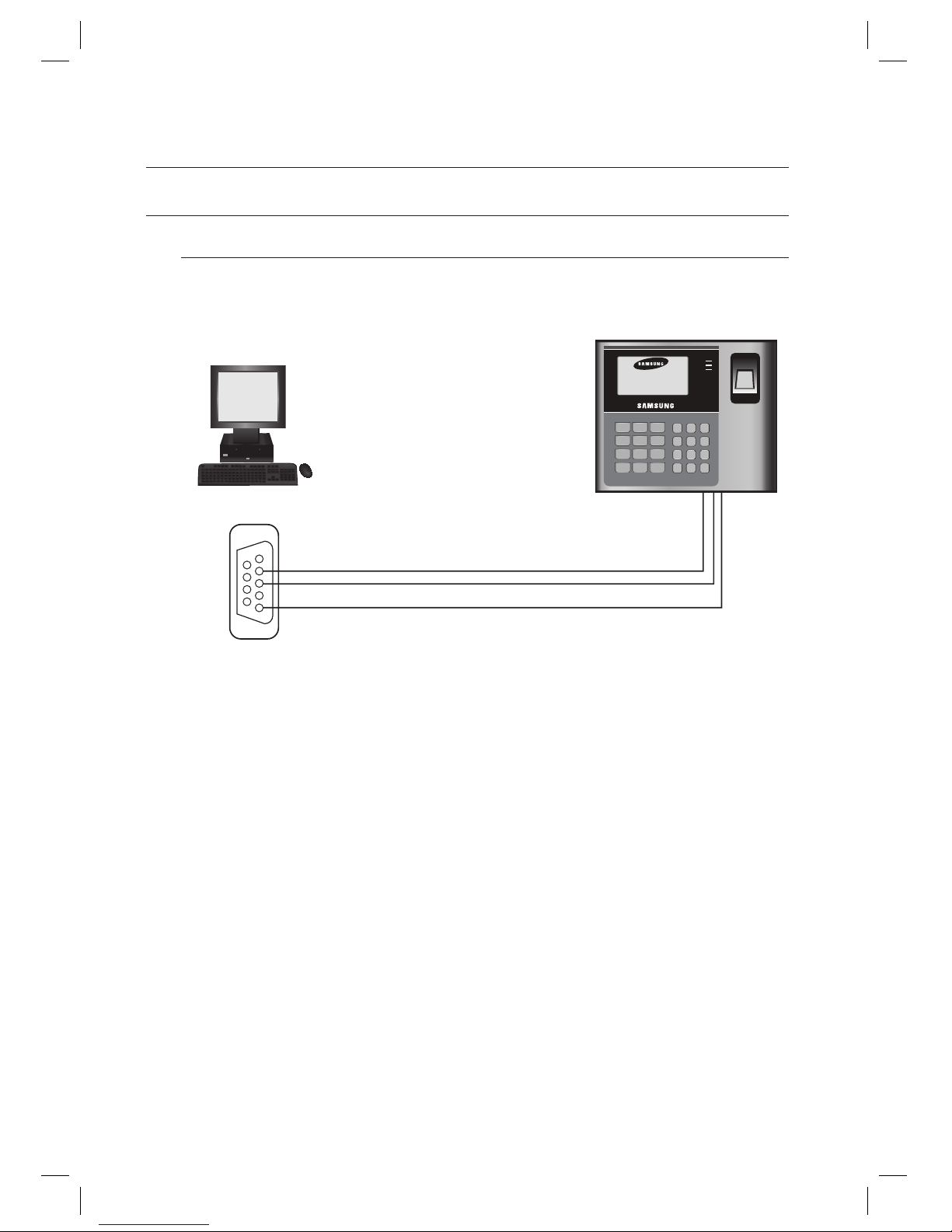
RS-232 Communication Port Connection
A 9-pin connector (serial communication connector, female) is needed to connect the product to the host PC via
RS-232 communication. Please follow the steps below:
Connect RS-232 TX (Black with white stripes) to the pin #2 (RXD) of the 9-pin female connector.
Connect RS-232 RX (Red with white stripes) to the pin #3 (TX) of the 9-pin female connector.
Connect the GND (black) line of the product to pin #5 of the 9-pin female connector.
Plug in the 9-pin female connector to serial port (COM port) of the host PC.
Install and launch the application (SAMS).
1.
2.
3.
4.
5.
2
3
5
1 32
654
7 98
ESC0ENT
F1 F2 F3
F4 F5 F6
F7 F8 F9
F10 F11 F12
Mon 01 / 01 / 2010
10 : 30 : 20
183
"-.
%003
Black with white stripes
Red with white stripes
Black
HOST PC
9pin Female Connector
RS-232
Page 21
English English _ 21
INSTALLATION AND EXTERNAL CONNECTION
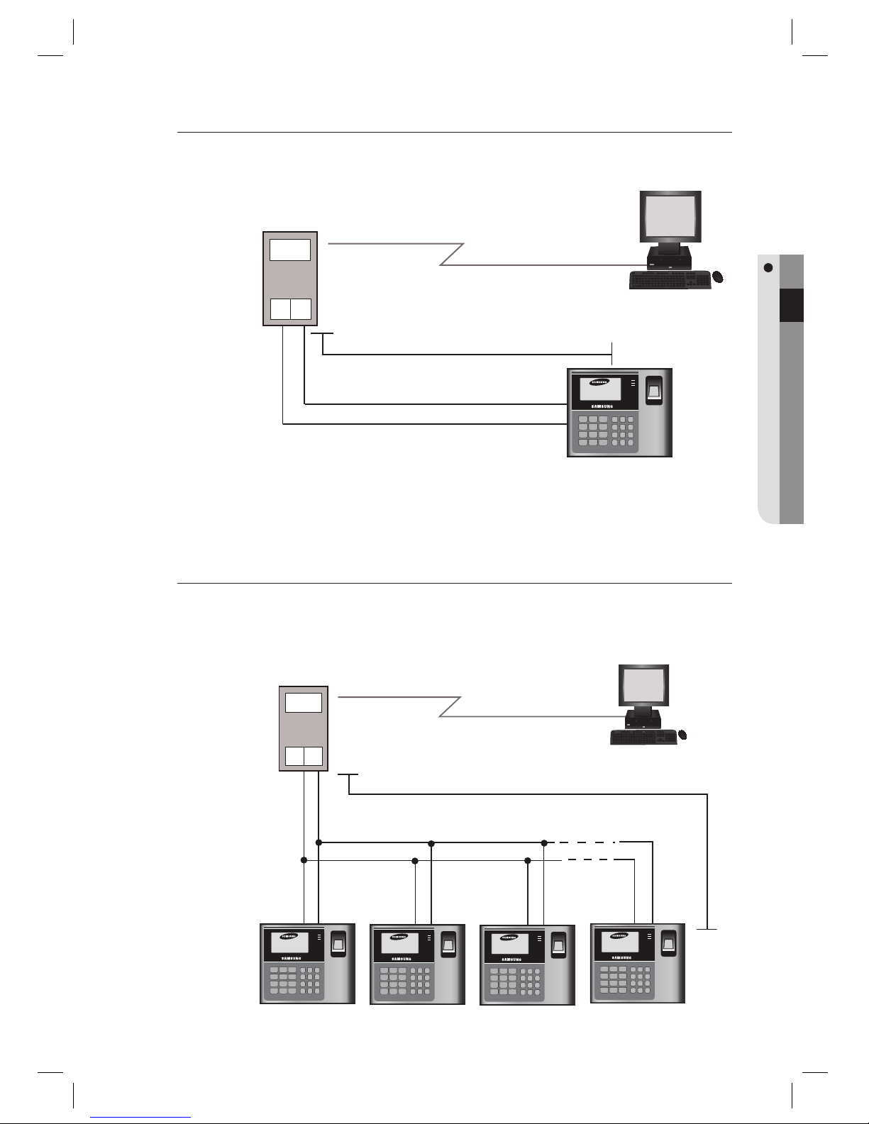
RS-485 Communication Port Connection (Standalone)
A RS-485/RS-232 converter is needed to make RS485 communications between the product and the host PC.
Please follow the steps below:
Connect the yellow RS-485 RTX (+) line to RS-485 A port of the converter.
Connect the gray RS-485 RTX (-) line to RS-485 B port of the converter.
Plug in the 9-pin connector (RS-232) of the converter into serial port (COM port) of the host PC.
Install and launch the application (SAMS).
RS-485 Communication Port Connection (Multiple Units)
A RS-485/RS-232 converter is needed to make RS-485 communications across a multiple of the products
and the host PC.
Please follow the steps below:
1.
2.
3.
4.
A B
1 32
6
54
7 98
ESC0ENT
F1 F2 F3
F4 F5 F6
F7 F8 F9
F10 F11 F12
Mon 01 / 01 / 2010
10 : 30 : 20
183
"-.
%003
Gray
Yellow
HOST PC
Max. 1200m
RS-485/RS-232
Converter
RS-232
RS-485
A B
1 32
6
54
7 98
ESC0ENT
F1 F2 F3
F4 F5 F6
F7 F8 F9
F10 F11 F12
Mon 01 / 01 / 2010
10 : 30 : 20
183
"-.
%003
1 32
6
54
7 98
ESC0ENT
F1 F2 F3
F4 F5 F6
F7 F8 F9
F10 F11 F12
Mon 01 / 01 / 2010
10 : 30 : 20
183
"-.
%003
1 32
6
54
7 98
ESC0ENT
F1 F2 F3
F4 F5 F6
F7 F8 F9
F10 F11 F12
Mon 01 / 01 / 2010
10 : 30 : 20
183
"-.
%003
1 32
6
54
7 98
ESC0ENT
F1 F2 F3
F4 F5 F6
F7 F8 F9
F10 F11 F12
Mon 01 / 01 / 2010
10 : 30 : 20
183
"-.
%003
Gray
Yellow
RS-485/RS-232
Converter
Max. 1200m
HOST PC
RS-232
RS-485
Page 22
22_
installation and external connection
installation and external connection
- Connect all RS-485 ports of the product in parallel.
Connect the yellow RS-485 RTX (+) line of one unit to the yellow RS-485 RTX (+) line of another unit.
Connect the gray RS-485 RTX (-) line of one unit to the gray RS-485 RTX (-) line of another unit.
Set a unique communication address (COMM ADDR) for each unit.
- Connect one RS-485 port of the product to the RS-485/RS-232 converter
Connect the yellow RS-485 RTX (+) line to the RS-485 A port of the converter.
Connect the gray RS-485 RTX (-) line to the RS-485 B port of the converter.
Plug the 9-pin connector (RS-232) of the converter into serial port (
COM port)
of the host PC.
Install and launch the application (SAMS).
RS-485 connection supports multi-drop communications up to 32 units.
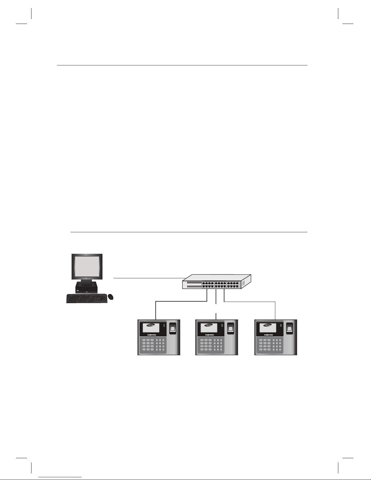
TCP/IP Communication Port Connection
To implement TCP/IP communications for the host PC, follow the steps below:
Connect the RJ45 jack of the unit to the RJ45 plug, the LAN cable of the network system.
Set a unique communication address (COMM ADDR) for each unit.
Install and launch the application (SAMS).
1.
2.
3.
1.
2.
3.
4.
M
1.
2.
3.
1 32
6
54
7 98
ESC0ENT
F1 F2 F3
F4 F5 F6
F7 F8 F9
F10 F11 F12
Mon 01 / 01 / 2010
10 : 30 : 20
183
"-.
%003
1 32
6
54
7 98
ESC0ENT
F1 F2 F3
F4 F5 F6
F7 F8 F9
F10 F11 F12
Mon 01 / 01 / 2010
10 : 30 : 20
183
"-.
%003
1 32
6
54
7 98
ESC0ENT
F1 F2 F3
F4 F5 F6
F7 F8 F9
F10 F11 F12
Mon 01 / 01 / 2010
10 : 30 : 20
183
"-.
%003
HUB
TCP/IP
PC
TCP/IP
Page 23
English English _ 23
INITIALIZATION
initialization
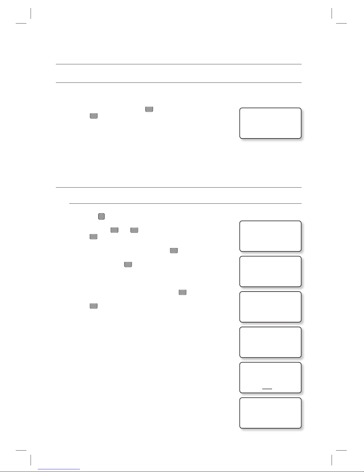
INITIALIZING THE SYSTEM
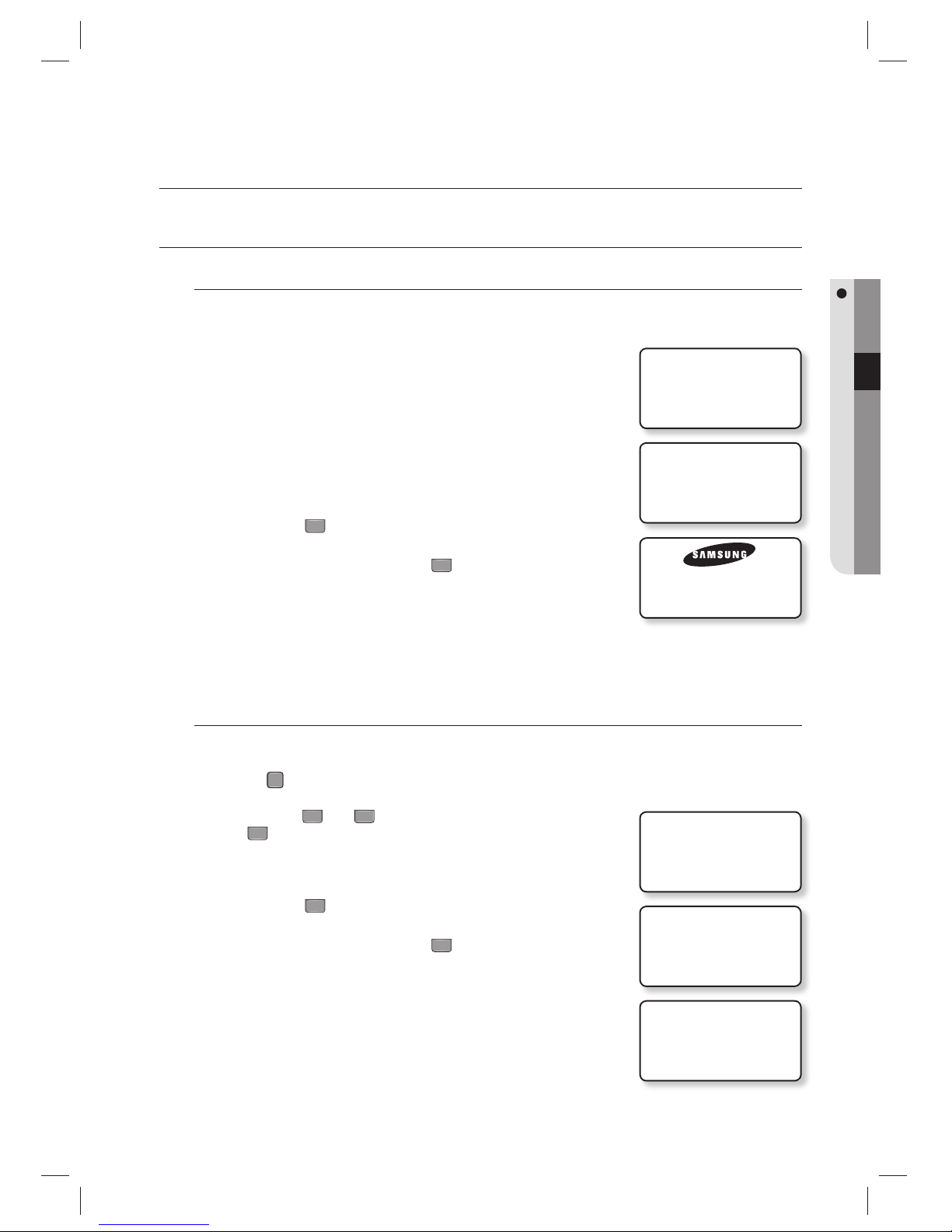
Initializing the system using the Initialize switch
Initialize the system using the Initialize switch on the rear of the product.
Check the power terminal on the rear of the product and disconnect the power
cable.
While holding the Initialize switch, connect the power cable again.
While holding the Initialize switch, wait until the “Initialize OK?” message
appears on the screen.
It takes about 8 seconds to proceed.
Do not press the Initialize switch while the initialization message appears.
Press the button
1
to proceed with the initialization process with the
“WAIT…” message on the screen.
To cancel Initializing the system, press
0
.
When the Initializing is done, you will move to the standby screen.
Note that the initialization process will restore all previous settings to the factory default.
System Initialization in Master Mode
You can Initialize the system through authentication of the master card. For entering the master mode, see page 24.
Press the
F
8
SETUP MENU button.
Use the buttons
4
and 6 to move to the SYSTEM INIT. item and
press
ENT
.
The initialization screen appears.
Press the button
1
to proceed with the initialization process with the
“WAIT…” message on the screen.
To cancel Initializing the system, press
0
.
When the Initializing is done, you will move to the standby screen.
Note that the initialization process will restore all previous settings to the factory
default.
1.
2.
3.
•
4.
•
5.
J
1.
2.
3.
4.
•
5.
J
INITIALIZE OK?
1:YES 0:NO
WAIT…
Sat 01 / 06 / 2010
10 : 30 : 20
1. SYSTEM INIT.
1. SYSTEM INIT.
1:YES, 0:NO
WAIT…
Page 24
24_ initialization
initialization
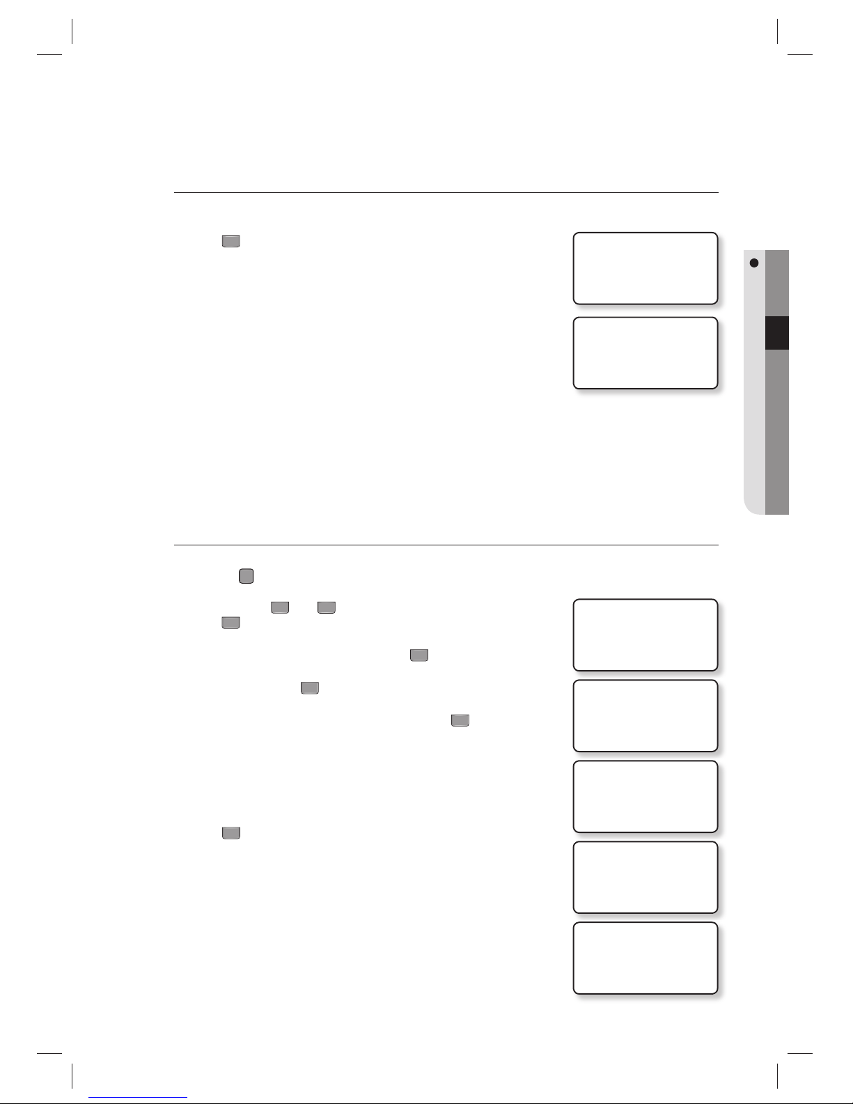
TO ACCESS THE MASTER MODE
Apply the power to the product.
When the booting is done, press 0 8 consecutive times (00000000) and
press
ENT
.
The master number of the initialization is “00000000” (“0000000000” for
SSA-S30X1).
If you have already registered the master ID, use the ID to get access.
When the system is initialized, the master number will be reset to “00000000”
If you have registered the master ID, you can not get access using “00000000”.
The master number for SSA-S30X1 is “0000000000 (10 digits)”.
REGISTERING A MASTER ID
To register a master card
Press the
F
7
SETUP MENU button.
Use the buttons
4
and 6 to move to the MASTER ID REG item and
press
ENT
.
Select a master ID index to register and press
ENT
.
To select a card, press
1
.
Place the master card to register on the product.
Enter the password for the master card and press
ENT
.
Press
0
to exit registering the master ID.
1.
2.
•
M
1.
2.
3.
4.
5.
6.
7.
WELCOME!!
* * * * * * * *
Mon 01 /01 2010
10 :30 : 20
4. MASTER ID REG
4. MASTER ID REG
MASTER #01
EMPTY
4. MASTER ID REG
1:CARD, 2:PIN
4. MASTER ID REG
SCANNING…
ID:12312345
P/W:5678
ENTER F/P FLAG
0:NOT USE 1: USE
ID:12312345
ENTER PASSWORD
Page 25
English English _ 25
INITIALIZATION
To register a master card along with your fi ngerprint
Follow the steps 1 through 6 above in “To register a master card”.
Press
1
to register your fi ngerprint.
Place your fi nger on the fi ngerprint scanner.
Release your fi nger, then put your fi nger onto the fi ngerprint scanner
again when the light turns on.
When done, the master ID and your fi ngerprint template will be registered.
The default master ID is “00000000”, and no fi ngerprint recognition is used.
If at least one master ID is registered, the default master ID, “00000000”, is no
longer available.
You can register up to a total of 10 master IDs (01 ~10).
To erase a master ID, enter “00000000” for the applicable master ID.
The master number for SSA-S30X1 is ““0000000000 (10 digits)”.
To register a master card PIN
Press the
F
7
SETUP MENU button.
Use the buttons
4
and 6 to move to the MASTER ID REG item and
press
ENT
.
Select a master ID index to register and press
ENT
.
To select a PIN, press
2
.
Enter the PIN for the master card to register and press
ENT
.
PIN Range
-SSA-S30x0 : Numeric letters in 8 digits
Ranges from 00000001 to 99999999
-SSA-S30x1 : Numeric letters in 10 digits
Ranges from 0000000001 to 4294967295
Press
0
to exit registering the PIN.
7.
8.
9.
10.
M
1.
2.
3.
4.
5.
•
6.
1/2
TO REGISTER F/P
PUT YOUR FINGER
2/2
LIFT AND
PUT YOUR FINGER
4. MASTER ID REG
00/00
4. MASTER ID REG
MASTER #1
EMPTY
4. MASTER ID REG
1:CARD, 2:PIN
4. MASTER ID REG
ENTER PIN
PIN:_
PIN: 12312345
ENTER F/P FLAG
0:NOT USE 1: USE
Page 26
26_ initialization
initialization
To register a master card PIN along with your fi ngerprint
Follow the steps 1 through 5 above in “To register a master card PIN”
Press
1
to register your fi ngerprint.
Place your fi nger on the fi ngerprint scanner.
Release your fi nger, then put your fi nger onto the fi ngerprint scanner
again when the light turns on.
When done, the master card PIN and your fi ngerprint template will be
registered.
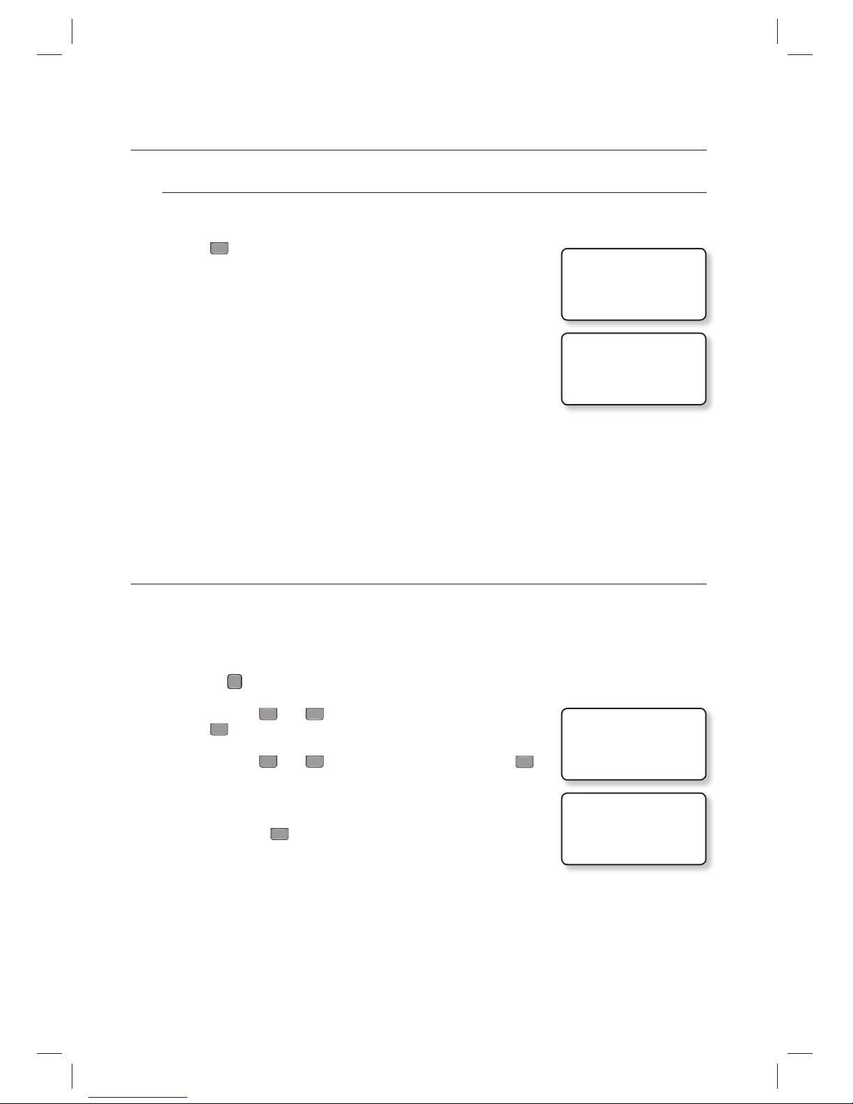
NAME DISPLAY
With “Name Display”, you can set to display the name of a user who enters.
The user name can be downloaded by using the provided application software only, and accepts only alphabetic
letters up to 8 characters. By using the unit, you can register a new user but cannot enter the user’s name. In case of
such a user’s accessing, no name will be displayed.
Press the
F
3
SETUP MENU button.
Use the buttons
4
and 6 to move to the NAME DISPLAY item and
press
ENT
.
Use the buttons
4
and 6 to select USE or NOT USE, and press
ENT
.
USE : Name Display is enabled.
NOT USE : Name Display is disabled.
When done, press
ENT
to save your settings.
If you set Name Display to “USE”, the maximum number of IDs will be limited to 10000.
Make sure no ID should have ever be registered before using this function.
6.
7.
8.
9.
1.
2.
3.
•
4.
M
1/2
TO REGISTER F/P
PUT YOUR FINGER
2/2
LIFT AND
PUT YOUR FINGER
6. NAME DISPLAY
NOT USE
6. NAME DISPLAY
J NOT USE
Page 27
English English _ 27
INITIALIZATION
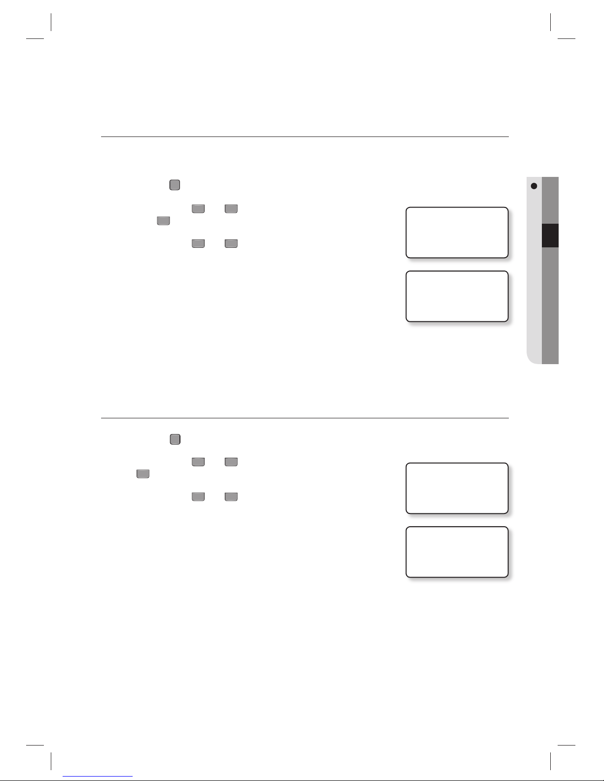
USER COUNT SETUP
You can select the maximum number of registered users to 10,000 or 20,000.
If you set the maximum user count to 20,000, the maximum number of events will be changed to 10,000.
Press the
F
3
SETUP MENU button.
Use the buttons
4
and 6 to move to the MAX USER SETUP item and
press
ENT
.
Use the buttons
4
and 6 to select a max user count.
10,000 : The max user count will be set to 10,000.
20,000 : The max user count will be set to 20,000.
Before setting the user count, you must initialize the system.
LANGUAGE SETUP
Press the
F
1
SETUP MENU button.
Use the buttons
4
and 6 to move to the LANGUAGE item and press
ENT
.
Use the buttons
4
and 6 to select a max user count.
ENGLISH
ITALIANO
FRANÇAIS
(Optional language : Español, Deutsch)
The default language is ENGLISH.
By optional, Spanish, German are supported.
1.
2.
3.
•
M
1.
2.
3.
•
M
5. MAX USER SETUP
10000
5. MAX USER SETUP
J 10000
1. LANGUAGE
ENGLISH
1. LANGUAGE
JENGLISH
Page 28
28_ initialization
initialization
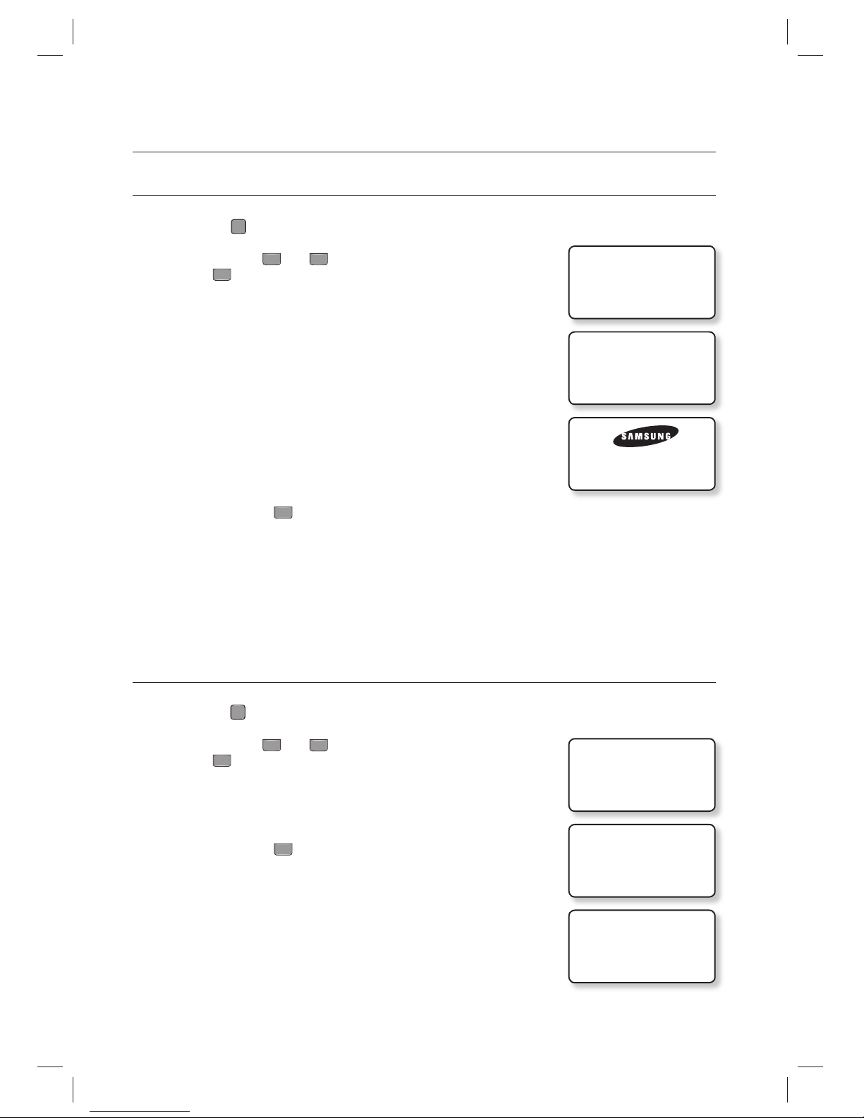
DATE/TIME SETUP
Press the
F
1
SETUP MENU button.
Use the buttons
4
and 6 to move to the SET DATE/TIME item and
press
ENT
.
Enter the values of year, month, day, hour, minute, second, and day of the
week in sequence.
YYYY : Year (4 digits)
MM : Month (2 digits)
DD : Day (2 digits)
hh : Hour (2 digits)
mm : Minute (2 digits)
ss : Second (2 digits)
w : Day of the week (1 digit)
1- Sunday, 2-Monday, 3-Tuesday, 4-Wednesday, 5-Thursday, 6-Friday,
7-Saturday
When done, press
ENT
to save your settings.
Enter each value for Date/Time to fi t the respective digits.
COMMUNICATION ADDRESS SETUP
Press the
F
1
SETUP MENU button.
Use the buttons
4
and 6 to move to the COMM ADDR SET item and
press
ENT
.
Enter the 3-digit communication address number.
Ex) if you set the COMM ADDR to 12, press 012 for that.
When done, press
ENT
to save your settings.
The default address is set to “000”.
Select a number between 000 and 255 for the address.
Each product in the same loop should have a unique communication address.
1.
2.
3.
•
4.
M
1.
2.
3.
•
4.
M
2. SET DATE/TIME
YYYYMMDDhhmmssw
_______________
2. SET DATE/TIME
201001011030202
Mon 01 / 01 / 2010
10:30 20
7. COMM ADDR SET
000
7. COMM ADDR SET
_00
7. COMM ADDR SET
012
Page 29
English English _ 29
INITIALIZATION
BAUD RATE SETUP
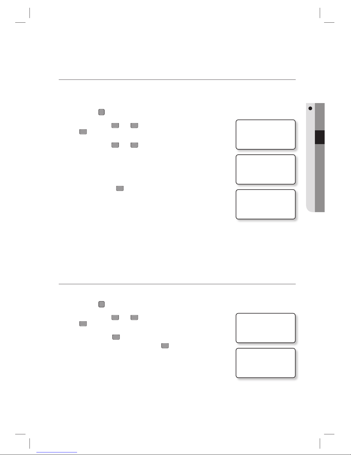
This product supports 9600, 19200, 38400, and 57600 bps, and it is set to 57600 bps by default.
An improper speed setting can cause a communication error so ensure that you specify the same speed in the same
network.
Press the
F
1
SETUP MENU button.
Use the buttons
4
and 6 to move to the BAUD RATE item and press
ENT
.
Use the buttons
4
and 6 to select a serial communication speed.
9600
19200
38400
57600
When done, press
ENT
to save your settings.
If you encounter a problem with the communication, check the followings fi rst.
- Check the communication addresses for this product and the host PC
(software).
- Check the baud rate settings of each of the host PC and this product.
- Check the communication port and cable.
- Check the host PC for the port settings.
FACTORY DEFAULTS
All menu settings will return to the factory default. (The memory is not deleted.)
Press the
F
8
SETUP MENU button.
Use the buttons
4
and 6 to move to the DEFAULT SET item and press
ENT
.
Press the button
1
to restore the menu settings to the default.
To cancel initialization, press the button
0
.
1.
2.
3.
•
4.
M
1.
2.
3.
•
8. BAUD RATE
57600
8. BAUD RATE
J19200
8. BAUD RATE
19200
6. DEFAULT SET
6. DEFAULT SET
1:YES, 0:NO
Page 30
30_ reader mode setup
reader mode setup
READER #1 MODE
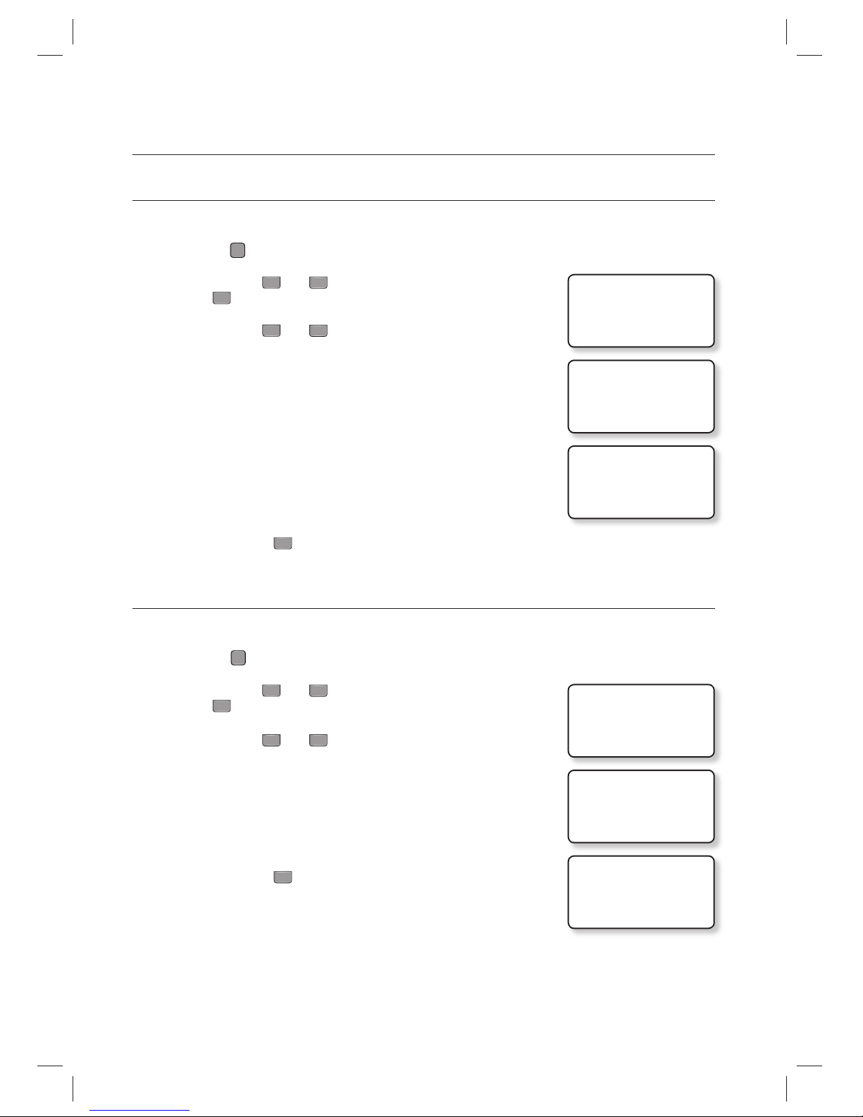
READER#1 is the default reader that is built in this product.
Press the
F
1
SETUP MENU button.
Use the buttons
4
and 6 to move to the READER#1 MODE item and
press
ENT
.
Use the buttons
4
and 6 to select a reader mode.
3 modes are available for your choice.
ID ONLY : In this mode, you can get access only with the proximity card
or ID number.
ID +F/P(P/W) : In this mode, you can get access through the fingerprint
authentication after entering the proximity card or ID
number.
If you have not registered your fingerprint, you can get
access with the password authentication.
ID+P/W+F/P : In this mode, you can get access through the two-pass
authentication of the password and your fingerprint after
using the proximity card or entering the ID number.
When done, press
ENT
to save your settings.
READER #2 MODE
READER#2 is an external reader for exit.
Press the
F
1
SETUP MENU button.
Use the buttons
4
and 6 to move to the READER#2 MODE item and
press
ENT
.
Use the buttons
4
and 6 to select a reader mode.
2 modes are available for your choice.
ID ONLY : In this mode, you can get access only with the proximity card
or ID number.
ID+P/W : In this mode, you can get access through the password
authentication after using the proximity card or entering the ID
number.
When done, press
ENT
to save your settings.
1.
2.
3.
•
4.
1.
2.
3.
•
4.
3. READER#1 MODE
ID ONLY
3. READER#1 MODE
JID+F/P(P/W)
3. READER#1 MODE
ID+F/P(P/W)
4. READER#2 MODE
ID ONLY
4. READER#2 MODE
JID+P/W
4. READER#2 MODE
ID+P/W
Page 31
English English _ 31
READER MODE SETUP
READER #1 KEY INPUT
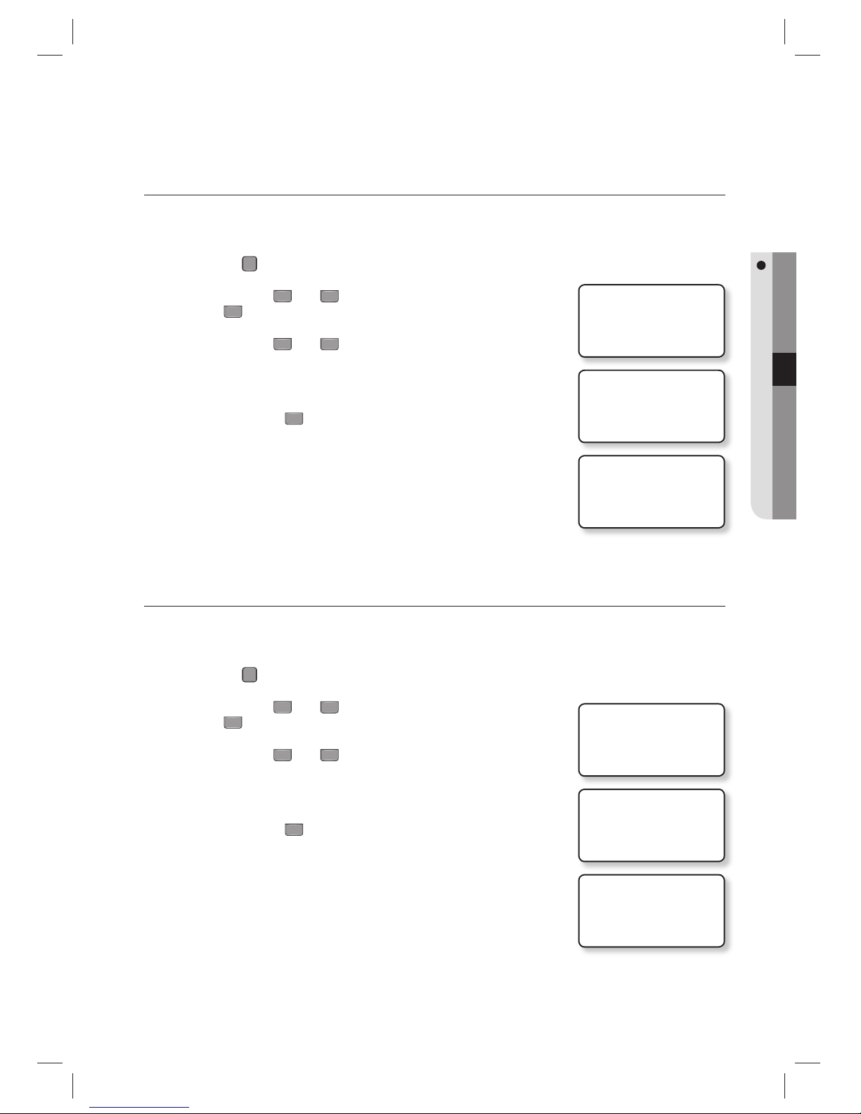
This enables you to use the keypad (numeric keypad) of READER #1 to enter the ID.
If you want to use the registered ID (card number or PIN) to get access, set this mode to USE.
Press the
F
1
SETUP MENU button.
Use the buttons
4
and 6 to move to the RD#1 KEY INPUT item and
press
ENT
.
Use the buttons
4
and 6 to select the use of the keypad of READER#1.
USE :
If set, you can get access using the keypad input.
NOT USE : If set, you can not get access using the keypad input.
When done, press
ENT
to save your settings.
READER #2 KEY INPUT
This enables you to use the keypad of READER #2 (numeric keypad of the external device) to enter the ID.
If you want to use the registered ID (card number or PIN) to get access, set this mode to USE.
Press the
F
1
SETUP MENU button.
Use the buttons
4
and 6 to move to the RD#2 KEY INPUT item and
press
ENT
.
Use the buttons
4
and 6 to select the use of the keypad of READER#2.
USE :
If set, you can get access using the keypad input.
NOT USE : If set, you can not get access using the keypad input.
When done, press
ENT
to save your settings.
1.
2.
3.
•
4.
1.
2.
3.
•
4.
5. RD#1 KEY INPUT
NOT USE
5. RD#1 KEY INPUT
J USE
5. RD#1 KEY INPUT
USE
6. RD#2 KEY INPUT
NOT USE
6. RD#2 KEY INPUT
J USE
6. RD#2 KEY INPUT
USE
Page 32
32_ reader mode setup
reader mode setup
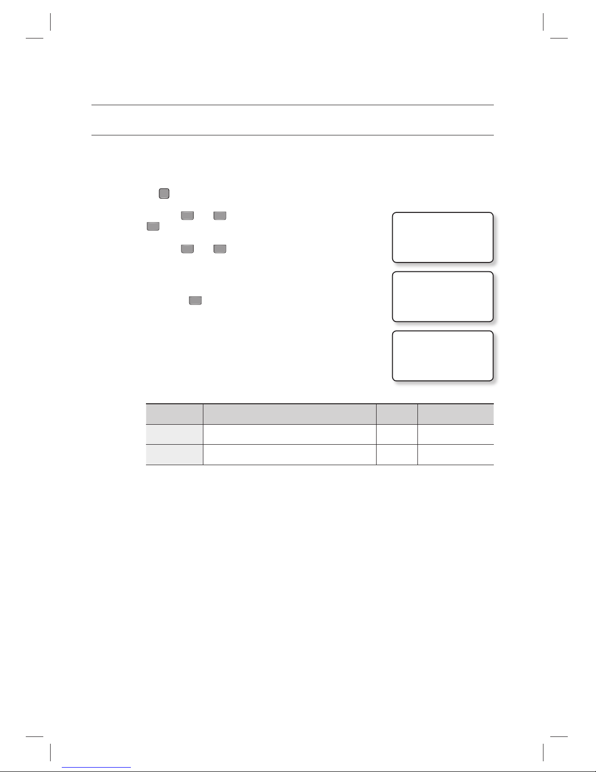
DUAL FINGERPRINT MODE
In Dual Fingerprint mode, you can register two fi ngerprints for one user ID.
If one of your fi ngers is damaged with Dual Fingerprint mode set to USE, you can use the other fi nger registered for the
authentication.
Press the
F10
SETUP MENU button.
Use the buttons
4
and 6 to move to the DUAL F/P MODE item and
press
ENT
.
Use the buttons
4
and 6 to select the use of Dual Fingerprint mode.
USE : If set, you can use the Dual Fingerprint mode.
NOT USE :
If set, Dual Fingerprint mode is disabled.
When done, press
ENT
to save your settings.
For registering fi ngerprints, see the following table.
DUAL FINGER Template/Fingerprint Count
Success
Ratio
Recommended
Authentication Mode
NOT USE
2 fi ngerprint templates for one fi nger
High Identifi cation mode
USE
1 fi ngerprint template for each of 2 different fi ngers
Low Verifi cation mode
Make sure not to mix Dual Finger enable/disable confi gurations for multiple units.
Otherwise, it may degrade the recognition performance or cause data communication errors.
If you switch the Dual Finger setup from disabled to enabled, all systems should have the consistent setups and
registered fi ngerprints must be registered again. Switching to disabled requires the same.
Before registering fi ngerprints and transfer data, make sure to setup all systems to have consistent setting at the
beginning.
1.
2.
3.
•
4.
M
J
1. DUAL F/P MODE
NOT USE
1. DUAL F/P MODE
JNOT USE
1. DUAL F/P MODE
USE
Page 33
English English _ 33
READER MODE SETUP
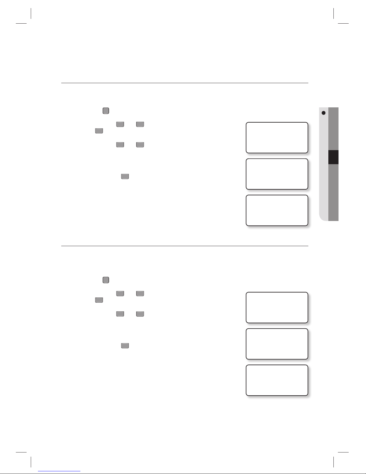
2. ADAPTIVE MODE
NOT USE
2. ADAPTIVE MODE
JNOT USE
2. ADAPTIVE MODE
USE
ADAPTIVE MODE
In Adaptive mode, the fi ngerprint image will be automatically compensated in an attempt to increase the successful
recognition rate of fi ngerprint authentication.
Press the
F10
SETUP MENU button.
Use the buttons
4
and 6 to move to the ADAPTIVE MODE item and
press
ENT
.
Use the buttons
4
and 6 to select the use of Adaptive mode.
USE : If set, you can use the Adaptive mode
NOT USE :
If set, Adaptive mode is disabled
When done, press
ENT
to save your settings.
In Adaptive mode, it may take longer to recognize the fi ngerprint.
Registering and recognizing fi ngerprints in ADAPTIVE MODE, the red LED of the
optical sensor blinks multiple times while capturing the fi ngerprint.
IDENTIFICATION MODE
You can select the use of 1:N Identifi cation mode. In this mode, the product analyzes the input fi ngerprint against all of
registered fi ngerprint data without demanding the input of the card or ID number, then it decides to authorize or
unauthorized the access.
Press the
F10
SETUP MENU button.
Use the buttons
4
and 6 to move to the IDENTIFICATION item and
press
ENT
.
Use the buttons
4
and 6 to select the use of Identifi cation mode.
USE : If set, you can use the Identifi cation mode
NOT USE :
If set, Identification mode is disabled
When done, press
ENT
to save your settings.
1.
2.
3.
•
4.
M
1.
2.
3.
•
4.
3. IDENTIFICATION
NOT USE
3. IDENTIFICATION
JNOT USE
3. IDENTIFICATION
USE
Page 34
34_ user management
user management
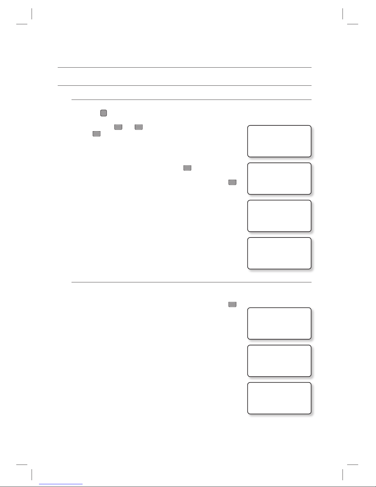
REGISTERING ID IN QUICK MODE
To register ID
Press the
F12
SETUP MENU button.
Use the buttons
4
and 6 to move to the REGISTRATION item and
press
ENT
.
Use one of the following two ways to enter an ID:
Place the card on the main unit to display the card ID on the screen.
Use the keypad to enter the number and press
ENT
.
Enter the password and select whether to use the fi ngerprint and press
ENT
.
Set FINGER to 0.
ID registration is completed.
Registering in Quick mode will set TA and TB to 00, and RD, MA, MB, LV to 0.
(Refer to page 35.)
To register ID along with fi ngerprint
Repeat steps 1 through 3 in “To register ID” above.
Enter the password and select whether to use the fi ngerprint and press
ENT
.
Set FINGER to 1.
Place your fi nger on the fi ngerprint scanner.
Release your fi nger, then put your fi nger onto the fi ngerprint scanner again
when the light turns on.
Your ID and fi ngerprint are registered.
1.
2.
3.
•
•
4.
•
5.
•
4.
•
5.
6.
7.
(QUICK MODE)
1. REGISTRATION
1. REGISTRATION
ID:_
ENTER PIN
PUT ID CARD
1. REGISTRATION
ID:12345678
PASS WORD:_
FINGER :0-N, 1-Y
ID REGISTERED!
1/2
TO REGISTER F/P
PUT YOUR FINGER
2/2
LIFT AND
PUT YOUR FINGER
FP QUALITY
Q_#1[4] Q_#2[4]
ID REGISTERED!
Page 35
English English _ 35
USER MANAGEMENT
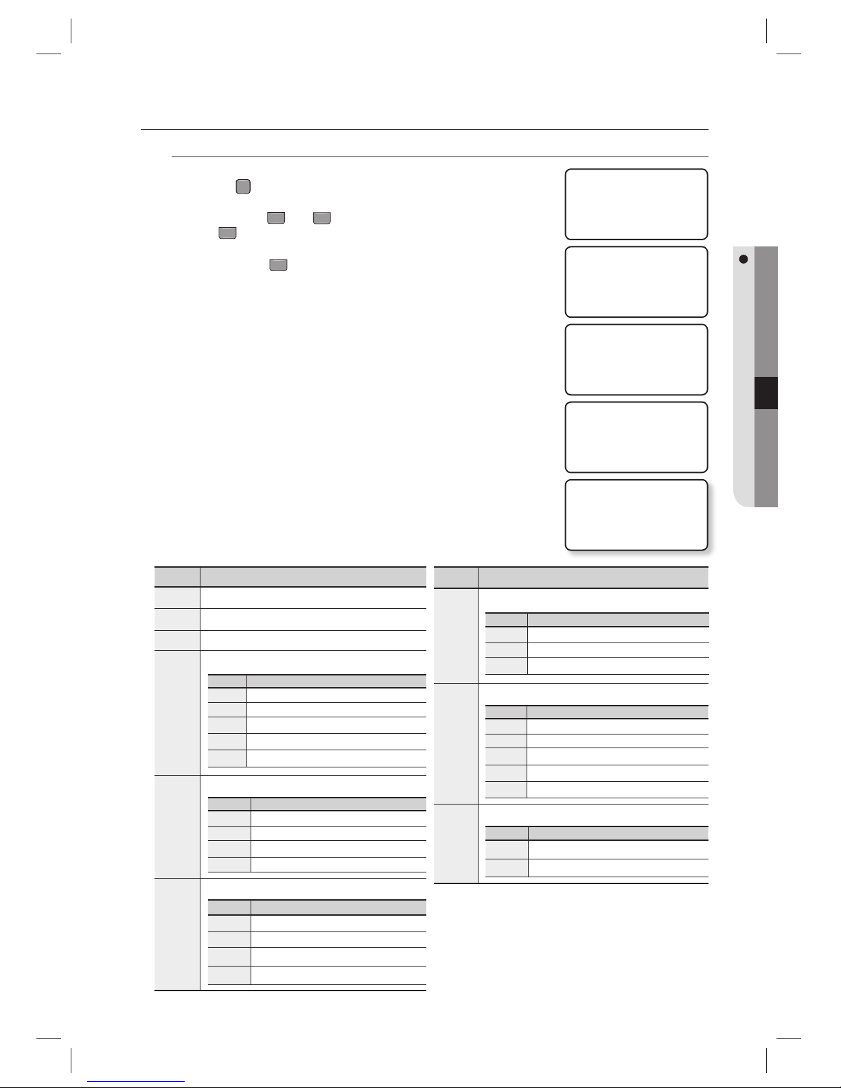
REGISTERING THE ID
To register the ID card
Press the
F
7
SETUP MENU button.
Use the buttons
4
and 6 to move to the REGISTRATION item and
press
ENT
.
Press the button
1
to select CARD.
For card registration, select the card to register the ID.
For PIN registration, select PIN and use the keypad to register the ID.
Put the card onto the main unit to display the card ID on the screen.
Set each of PW/TA/TB/C/RD/MA/MB/LV/FP.
For more information about each item, refer to “ID Registration Items” below.
Set FP to 0.
ID registration is completed.
1.
2.
3.
•
4.
5.
•
•
6.
Item Description
PW
4-digit password used in ID+PW
TA
Time schedule code for READER#1 (Internal reader)
TB
Time schedule code for READER#2 (external reader)
C
Permission code for the user ID
NO Description
0
Normal card
1
2-person authentication (administrator)
2
2-person authentication (visitor)
3
Set ARM/DISARM
4
Missing card
RD
Reader assignment to the card user
NO Description
0
READER#1, READER#2 assigned
1
READER#1 assigned
2
READER#2 assigned
3
READER#1, READER#2 assigned
MA
READER#1 operation mode for the registered user
NO Description
0
System Operation Mode
1
ID mode
2
ID+F/P(P/W)
3
ID+F/P+P/W
Item Description
MB
READER#2 operation mode for the registered user
NO Description
0
System Operation Mode
1
ID mode
2
ID+P/W
LV
Output operation level for the registered user
NO Description
0
Output Level 1 on access authentication
1
Output Level 1 on access authentication
2
Output Level 2 on access authentication
3
Output Level 3 on access authentication
4
Output Level 4 on access authentication
FP
Use/disuse of fi ngerprint
NO Description
0
Fingerprint not used.
1
Fingerprint used.
ID Registration Item (PW /TA/TB/C/RD/MA/MB/LV/FP)
❖
1. REGISTRATION
1. REGISTRATION
1:CARD 2:PIN
1. REGISTRATION
SCANNING…
1. REGISTRATION
ID:1230001
PW_ TA TB C
RD MA MB LV FP
ID REGISTERED!
Page 36
36_ user management
user management
To register the ID card along with your fi ngerprint
Follow the steps 1 through 4 in “To register the ID card” above
Set each of PW/TA/TB/C/RD/MA/MB/LV/FP.
For more information about each item, refer to “ID Registration Items” on
page 35.
Set FP to 1.
Press
ENT
.
Place your fi nger on the fi ngerprint scanner.
Release your fi nger, then put your fi nger onto the fi ngerprint scanner
again when the light turns on.
Your ID and fi ngerprint will be registered.
To register the PIN number
Press the
F
7
SETUP MENU button.
Use the buttons
4
and 6 to move to the REGISTRATION item and
press
ENT
.
Press the button
2
to select PIN.
For card registration, select the CARD to register the ID.
For PIN registration, select PIN and use the keypad to register the ID.
Use the keypad to enter the ID and press
ENT
.
Set each of PW/TA/TB/C/RD/MA/MB/LV/FP.
For more information about each item, refer to “ID Registration Items” on
page 35.
Set FP to 0.
ID registration is completed.
You can use the keypad to enter the ID in the following digits depending on the
model.
- PIN Range
SSA-S30x0 : Numeric letters in 4 ~ 8 digits
Ranges from 00000001 to 99999999
SSA-S30x1 : Numeric letters in 4 ~ 8 or 10 digits
Ranges from 0001 to 99999999, 0000000001 to 4294967295
5.
•
•
•
6.
7.
8.
1.
2.
3.
•
4.
5.
•
•
6.
M
1/2
TO REGISTER F/P
PUT YOUR FINGER
2/2
LIFT AND
PUT YOUR FINGER
FP QUALITY
Q_#1[4] Q_#2[4]
ID REGISTERED!
1. REGISTRATION
1. REGISTRATION
1:CARD 2:PIN
1. REGISTRATION
ID:
1. REGISTRATION
ID:1230001
PW_ TA TB C
RD MA MB LV FP
ID REGISTERED!
Page 37
English English _ 37
USER MANAGEMENT
To register the PIN number along with your fi ngerprint
Follow steps 1 through 4 in “To register the PIN number” above.
Set each of PW/TA/TB/C/RD/MA/MB/LV/FP.
For more information about each item, refer to “ID Registration Items” on
page 35.
Set FP to 1.
Press
ENT
.
Place your fi nger on the fi ngerprint scanner.
Release your fi nger, then put your fi nger onto the fi ngerprint scanner
again when the light turns on.
Your ID and fi ngerprint will be registered.
TO DELETE ID
A registered ID can be deleted by entering the ID using the card or keypad in ID DELETE mode.
The number of the ID to delete will be displayed on the screen.
Press the
F
7
SETUP MENU button.
Use the buttons
4
and 6 to move to the ID DELETE item and press
ENT
.
Enter the ID to delete, and press
ENT
.
If you enter the card, you don’t need to press
ENT
.
When the ID is deleted, you will see a message of “ID DELETED!!!” on the
screen.
If the entered ID is not registered with the product, you will see a message of “UNREGISTERED ID” on the screen.
If an ID that is out of the acceptable range is entered , “INVALID NUMBER” message appears.
The ID DELETE menu in QUICK MODE under [F12] is the same as ID DELETE under [F7].
5.
•
•
•
6.
7.
8.
1.
2.
3.
•
4.
M
1/2
TO REGISTER F/P
PUT YOUR FINGER
2/2
LIFT AND
PUT YOUR FINGER
FP QUALITY
Q_#1[4] Q_#2[4]
ID REGISTERED!
2.ID DELETE
2.ID DELETE
ENTER PIN
J_
ID DELETED!!!
Page 38
38_ user management
user management
VIEWING THE ID LIST
You can check the list of IDs registered with the product.
Press the
F
7
SETUP MENU button.
Use the buttons
4
and 6 to move to the ID LIST item and press
ENT
.
The list of registered IDs appears on the screen.
The list of registered IDs appears on the screen.
ID INDEX : Number of registered items
ID : ID number
C : ID permission code
PW : password
TA : Time schedule of READER #1
TB : Time schedule of READER #2
RD : Readers accessible
MA : Operation mode of READER #1
MB : Operation mode of READER #2
LV : Output level
FP: Use/disuse of fi ngerprint(0:disuse, 1:Use)
Use the buttons
4
and 6 to check other registered IDs.
The “EMPTY” message will appear if there is no user ID registered.
The “FIRST ID” message indicates that the ID displayed on the screen is the fi rst one.
The “LAST ID” message indicates that the ID displayed on the screen is the last one.
TO CHECK THE NUMBER OF REGISTERED IDs
You can check the total number of registered IDs.
Press the
F
7
SETUP MENU button.
Use the buttons 4 and 6 to move to the REG. ID COUNT item and
press
ENT
.
The number of registered IDs will be shown on the screen.
The number of registered IDs will be displayed in 5 digits.
1.
2.
3.
•
4.
M
1.
2.
3.
M
3.ID LIST
ID INDEX:00001
ID:12300001 C:0
PW0000 TA00 TB00
RD0 MA0 MB0 LV1 FP1
5. REG. ID COUNT
00123
Page 39
English English _ 39
USER MANAGEMENT
TO REMOVE ALL REGISTERED IDs
You can remove all of the registered user IDs.
Press the
F
8
SETUP MENU button.
Use the buttons 4 and 6 to move to the ALL ID CLEAR item and
press
ENT
.
Press the button 1 to delete all registered IDs.
To cancel the work, press the button
0
.
Please upload the ID data to the host PC before deletion, just for backup purposes.
TO CHECK THE NUMBER OF REGISTERED FINGERPRINTS
You can check the total number of registered fi ngerprints.
Press the
F10
SETUP MENU button.
Use the buttons 4 and 6 to move to the FP REG. COUNT item and
press
ENT
.
The number of registered / total recordable fi ngerprints will be shown.
1.
2.
3.
•
J
1.
2.
3.
3. ALL ID CLEAR
3. ALL ID CLEAR
1:YES, 0:NO
4. FP REG. COUNT
4. FP REG. COUNT
0021 / 1000
Page 40
40_ user management
user management
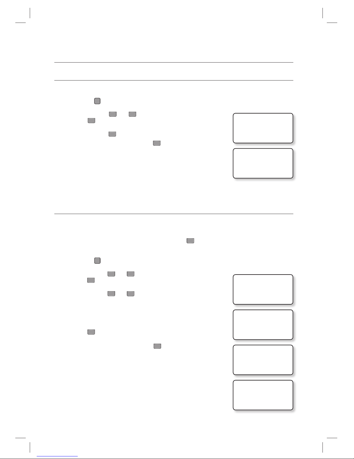
TO REMOVE THE MASTER IDs
If you want to remove all master IDs (card IDs), use this menu.
Press the
F
8
SETUP MENU button.
Use the buttons 4 and 6 to move to the MASTER ID CLR item and
press
ENT
.
Press the button 1 to delete all registered master IDs.
To cancel the work, press the button
0
.
Before removing all master IDs, ensure that the master IDs are no longer in use.
DURESS MODE
You can set Duress Mode for READER#1. Duress mode is a special feature that outputs a special alarm signal when a
it is forced to open the restricted area, whose default is NOT USE. When selecting USE, you are prompted to enter the
two-digit numbers for the Duress mode password, whose default is ‘00’.
If it is set to USE, enter the two-digit Duress password and press
ENT
; this will open the door normally, but the Duress
alarm signal is transmitted to the host PC.
Press the
F
2
SETUP MENU button.
Use the buttons
4
and 6 to move to the DURESS MODE item and
press
ENT
.
Use the buttons
4
and 6 to select USE.
NOT USE
: Duress Mode is disabled.
USE : If set to USE, proceed with the followings:
The DURESS password is shown.
Press
ENT
.
Enter the two-digit password and press
ENT
.
The Duress Mode password should be different from the Arm/Disarm code.
You can specify the output time for each signal out for Duress Alarm.
(See Page
47 for “Duress Mode Output Setup”.)
1.
2.
3.
•
J
1.
2.
3.
•
4.
5.
M
4. MASTER ID CLR
4.MASTER ID CLR
1:YES, 0:NO
6.DURESS MODE
J NOT USE
6.DURESS MODE
J USE
DURESS PASSWORD
00
ENTER DURESS P/W
█
Page 41
English English _ 41
USER MANAGEMENT
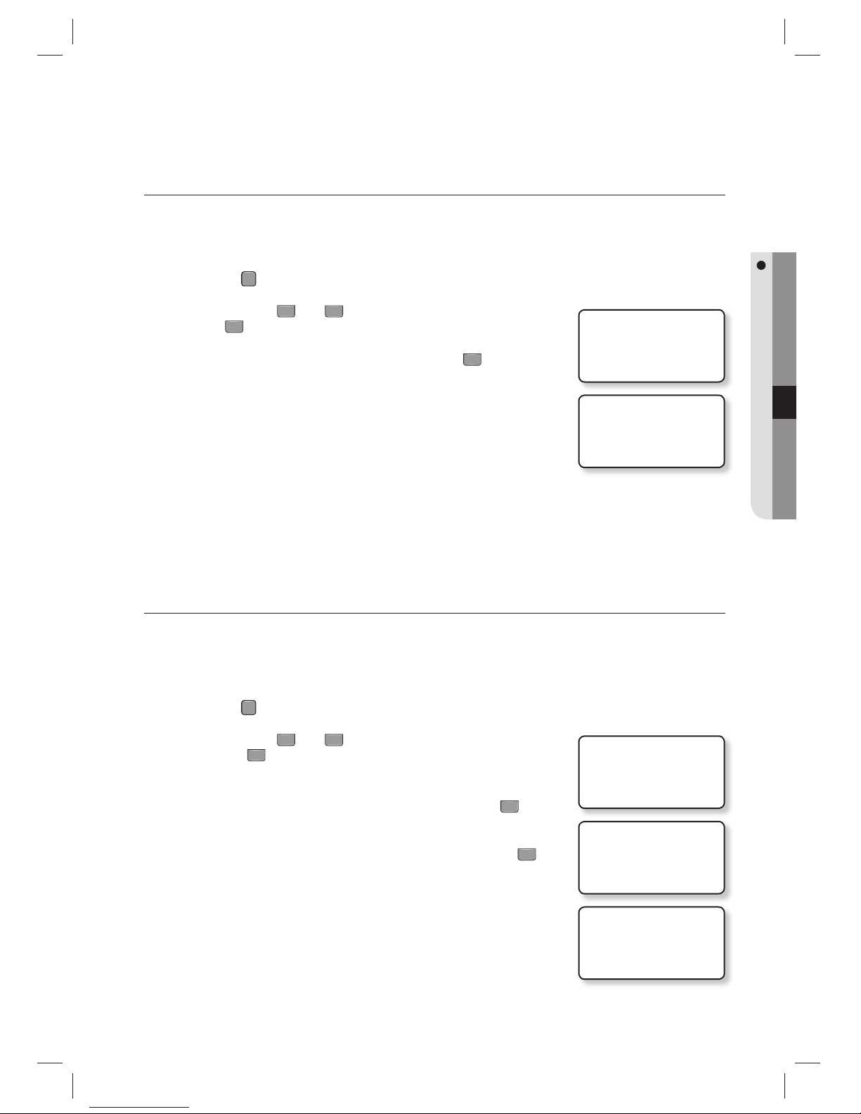
DOOR OPEN ALARM TIME SETUP
In this menu, you can set the delay time until the product triggers the door open alarm if the door stays open after the Door
Relay time. To use this function, the Door Contact sensor should have been installed on the entrance door. (see page 17)
The default is ‘03’.
Press the
F
2
SETUP MENU button.
Use the buttons 4 and 6 to move to the OPEN ALR TIME item and
press
ENT
.
Use the keypad to enter the time in two digits and press
ENT
.
00 : The alarm will sound shortly if the door stays open after the Door Relay
Time.
01~ 98 : The alarm will sound shortly if the door stays open after both of
Door Relay time and Door Delay alarm. (01~98 seconds)
99 : The Door Open alarm will not sound.
To use this function, the Door Contact sensor should have been installed on the entrance door.
ARM/DISARM
With the ARM/DISARM code active, you can set the ARM mode by entering the ARM code and presenting the card
(assigned Code 3 in registration) of a person who has the ARM/DISARM permissions. In this mode, all connected readers
will not take the card input any further. To release the ARM mode, enter the DISARM code and present the ARM/DISARM
card.
Press the
F
3
SETUP MENU button.
Use the buttons 4 and 6 to move to the ARM/DISARM SET item
and press
ENT
.
You are prompted to enter the ARM code.
Use the keypad to enter the ARM code in two digits and press
ENT
.
You are prompted to enter the DISARM code.
Use the keypad to enter the DISARM code in two digits and press
ENT
.
The Arm/Disarm code should be different from the Duress Mode password.
You can specify the output time for each signal out when ARM function is enabled.
(See Page 47 for “ARM/DISARM Output Setup”.)
1.
2.
3.
•
M
1.
2.
3.
4.
M
2.ARM/DISARM SET
00/00
ARM CODE
00
DISARM CODE
00
8.OPEN ALR TIME
03
8.OPEN ALR TIME
10
Page 42
42_ user management
user management
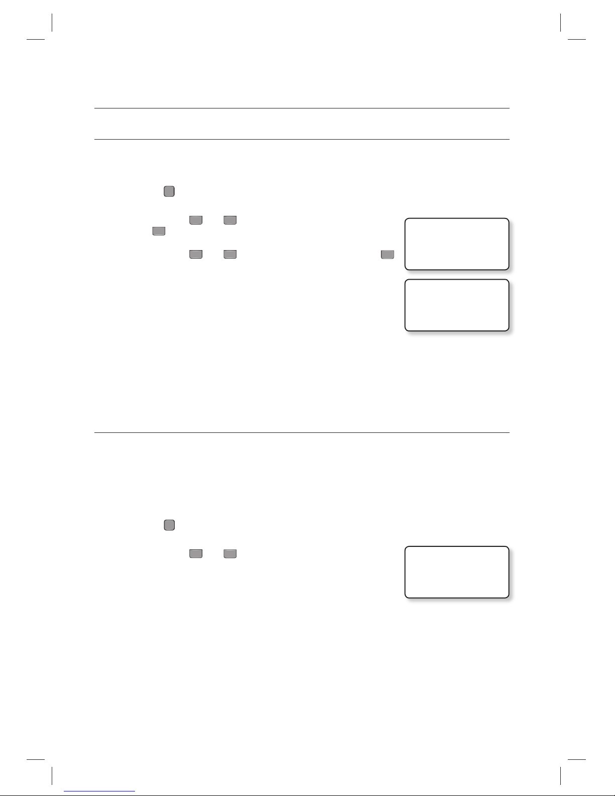
TWO MEN OPERATION MODE
With TWO MEN MODE active, the door will be opened if both administrator card and visitor card are entered in a row
within 10 seconds.
Press the
F
3
SETUP MENU button.
Use the buttons 4 and 6 to move to the TWO MEN MODE item and
press
ENT
.
Use the buttons
4
and 6 to select USE or NOT USE, and press
ENT
.
USE
: TWO MEN MODE is enabled.
NOT USE : TWO MEN MODE is disabled.
To enable this function, the preferred administrator card should be assigned code 1, while the visitor card be
assigned code 2. (See Page 35 for “Registering the ID ”.)
TO CHECK THE NUMBER OF EVENTS
You can check the total number of events stored in the memory. When an event is stored in the memory, the count will
increase accordingly.
The total number of events is 20,000.
Once a specifi c event is uploaded successfully to the host PC, it will be removed from the internal memory.
Press the
F
7
SETUP MENU button.
Use the buttons 4 and 6 to move to the EVENT COUNT item.
The number of events stored in the memory will be shown.
To remove the event, refer to “To delete all events”. (see page 43)
The number of registered IDs will be displayed in 5 digits.
When the memory is full, please refer to “Event Memory Setup”. (see page 61)
1.
2.
3.
•
M
1.
2.
3.
M
3.TWO MEN MODE
J NOT USE
3.TWO MEN MODE
J USE
6.EVENT COUNT
00014
Page 43
English English _ 43
USER MANAGEMENT
TO REMOVE ALL EVENTS
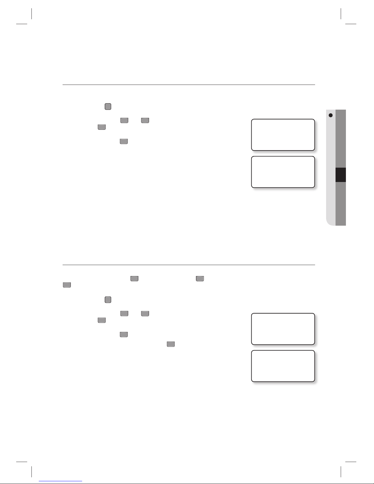
If the event memory is full or you want to change the number of IDs, you can use this menu to clear the event memory.
Press the
F
8
SETUP MENU button.
Use the buttons 4 and 6 to move to the EVENT CLEAR item and
press
ENT
.
Press the button 1 to remove all events.
To cancel the work, press the button 0.
To reserve the events, upload them to the host PC before deletion.
TO REMOVE THE TIME SCHEDULE
All time schedules (01~10), all holiday schedules (01~10), holiday codes, and time schedules for reader#1 and reader#2
modes can be deleted. With the
ENT
button pressed, press the 1 button to remove all time schedules or press the
0
button to cancel the work.
Press the
F
8
SETUP MENU button.
Use the buttons 4 and 6 to move to the T/S CLEAR item and
press
ENT
.
Press the button 1 to remove all time schedules.
To cancel the work, press the button
0
.
You will see the message as shown at the right.
Before removing all time schedules, ensure that they are no longer in use.
1.
2.
3.
•
J
1.
2.
3.
•
•
J
2.EVENT CLEAR
1:YES, 0:NO
DELETE ALL EVENT
WAIT…
5.T/S CLEAR
1:YES, 0:NO
DELETE TS
WAIT…
Page 44
44_ I/O time setup
I/O time setup
EXIT BUTTON OUTPUT
Press the
F
5
SETUP MENU button.
Use the buttons 4 and 6 to move to the EXIT BUTTON item and
press
ENT
.
You can make input when the prompt blinks.
Use the keypad to enter the time for each output operation and press
ENT
.
DR : Door relay output
AR : Alarm relay output
T1 : TTL #1 output
T2 : TTL #2 output
BZ : Buzzer output
The output time differs, depending on the time unit.
If the time unit is 0.1 (second), you can specify the value between 0.0 and 9.8 second; if set to 1 (second), you can
specify between 0 and 98 seconds.
For the time unit, refer to the ‘Time Unit Setup’ under the advanced setup. (see page 54)
If you enter 99 for the value, the product stays in output mode until you change the setting regardless of the time
unit.
DOOR CONTACT SENSOR SETUP
You can specify the signal output if a door is forcibly opened without through the normal authentication process. (The Door
Contact sensor should have been installed.)
Press the
F
5
SETUP MENU button.
Use the buttons 4 and 6 to move to the DOOR CONTACT item and
press
ENT
.
You can make input when the prompt blinks.
Use the keypad to enter the time for each output operation and press
ENT
.
DR : Door relay output
AR : Alarm relay output
T1 : TTL #1 output
T2 : TTL #2 output
BZ : Buzzer output
The output time differs, depending on the time unit.
If the time unit is 0.1 (second), you can specify the value between 0.0 and 9.8 second; if set to 1 (second), you can
specify between 0 and 98 seconds.
For the time unit, refer to the ‘Time Unit Setup’ under the advanced setup. (see page 54)
If you enter 99 for the value, the product stays in output mode until you change the setting regardless of the time
unit.
1.
2.
3.
•
M
1.
2.
3.
•
M
1.EXIT BUTTON
DR AR T1 T2 BZ
03 00 00 00 00
1.EXIT BUTTON
DR AR T1 T2 BZ
_0 00 00 00 00
2.DOOR CONTACT
DR AR T1 T2 BZ
00 99 00 00 00
2.DOOR CONTACT
DR AR T1 T2 BZ
_0 99 00 00 00
Page 45
English English _ 45
I/O TIME SETUP
AUXILIARY INPUT #1 SETUP
Press the
F
5
SETUP MENU button.
Use the buttons 4 and 6 to move to the AUX INPUT #1 item and
press
ENT
.
You can make input when the prompt blinks.
Use the keypad to enter the time for each output operation and press
ENT
.
DR : Door relay output
AR : Alarm relay output
T1 : TTL #1 output
T2 : TTL #2 output
BZ : Buzzer output
The output time differs, depending on the time unit.
If the time unit is 0.1 (second), you can specify the value between 0.0 and 9.8 second; if set to 1 (second), you can
specify between 0 and 98 seconds.
For the time unit, refer to the ‘Time Unit Setup’ under the advanced setup. (see page 54)
If you enter 99 for the value, the product stays in output mode until you change the setting regardless of the time
unit.
AUXILIARY INPUT #2 SETUP
Press the
F
5
SETUP MENU button.
Use the buttons 4 and 6 to move to the AUX INPUT #2 item and
press
ENT
.
You can make input when the prompt blinks.
Use the keypad to enter the time for each output operation and press
ENT
.
DR : Door relay output
AR : Alarm relay output
T1 : TTL #1 output
T2 : TTL #2 output
BZ : Buzzer output
The output time differs, depending on the time unit.
If the time unit is 0.1 (second), you can specify the value between 0.0 and 9.8 second; if set to 1 (second), you can
specify between 0 and 98 seconds.
For the time unit, refer to the ‘Time Unit Setup’ under the advanced setup. (see page 54)
If you enter 99 for the value, the product stays in output mode until you change the setting regardless of the time
unit.
1.
2.
3.
•
M
1.
2.
3.
•
M
3.AUX INPUT#1
DR AR T1 T2 BZ
00 00 00 00 00
3.AUX INPUT#1
DR AR T1 T2 BZ
_0 00 00 00 00
4.AUX INPUT#2
DR AR T1 T2 BZ
00 00 00 00 00
4.AUX INPUT#2
DR AR T1 T2 BZ
_0 00 00 00 00
Page 46
46_ I/O time setup
I/O time setup
TAMPER ALARM OUTPUT SETUP
You can set the signal that you want to output if the device is dismantled forcibly.
Press the
F
5
SETUP MENU button.
Use the buttons 4 and 6 to move to the TAMPER ALARM item and
press
ENT
.
You can make input when the prompt blinks.
Use the keypad to enter the time for each output operation and press
ENT
.
DR : Door relay output
AR : Alarm relay output
T1 : TTL #1 output
T2 : TTL #2 output
BZ : Buzzer output
The output time differs, depending on the time unit.
If the time unit is 0.1 (second), you can specify the value between 0.0 and 9.8 second; if set to 1 (second), you can
specify between 0 and 98 seconds.
For the time unit, refer to the ‘Time Unit Setup’ under the advanced setup. (see page 54)
If you enter 99 for the value, the product stays in output mode until you change the setting regardless of the time
unit.
CUT OFF OUTPUT SETUP
You can set the output options when any of the input line is cut off.
The input cutoff check should have been activated. (see page 60)
Press the
F
5
SETUP MENU button.
Use the buttons 4 and 6 to move to the CUT OFF ALARM item and
press
ENT
.
You can make input when the prompt blinks.
Use the keypad to enter the time for each output operation and press
ENT
.
DR : Door relay output
AR : Alarm relay output
T1 : TTL #1 output
T2 : TTL #2 output
BZ : Buzzer output
The output time differs, depending on the time unit.
If the time unit is 0.1 (second), you can specify the value between 0.0 and 9.8 second; if set to 1 (second), you can
specify between 0 and 98 seconds.
For the time unit, refer to the ‘Time Unit Setup’ under the advanced setup. (see page 54)
If you enter 99 for the value, the product stays in output mode until you change the setting regardless of the time
unit.
1.
2.
3.
•
M
1.
2.
3.
•
M
5.TAMPER ALARM
DR AR T1 T2 BZ
00 99 99 99 99
5.TAMPER ALARM
DR AR T1 T2 BZ
_0 99 99 99 99
6.CUT OFF ALARM
DR AR T1 T2 BZ
00 00 00 00 00
6.CUT OFF ALARM
DR AR T1 T2 BZ
_0 00 00 00 00
Page 47
English English _ 47
I/O TIME SETUP
DURESS MODE OUTPUT SETUP
You can specify the output time for Duress mode.
Press the
F
5
SETUP MENU button.
Use the buttons 4 and 6 to move to the DURESS ALARM item and
press
ENT
.
You can make input when the prompt blinks.
Use the keypad to enter the time for each output operation and press
ENT
.
DR : Door relay output
AR : Alarm relay output
T1 : TTL #1 output
T2 : TTL #2 output
BZ : Buzzer output
Duress Alarm must be enabled (See Page 40 for “Duress Mode”.)
The output time differs, depending on the time unit.
If the time unit is 0.1 (second), you can specify the value between 0.0 and 9.8 second; if set to 1 (second), you can
specify between 0 and 98 seconds.
For the time unit, refer to the ‘Time Unit Setup’ under the advanced setup. (see page 54)
If you enter 99 for the value, the product stays in output mode until you change the setting regardless of the time
unit.
ARM/DISARM OUTPUT SETUP
You can specify the output time for ARM/DISARM mode.
Press the
F
5
SETUP MENU button.
Use the buttons 4 and 6 to move to the ARM/DISARM SET item
and press
ENT
.
You can make input when the prompt blinks.
Use the keypad to enter the time for each output operation and press
ENT
.
DR : Door relay output
AR : Alarm relay output
T1 : TTL #1 output
T2 : TTL #2 output
BZ : Buzzer output
ARM/DISARM must be enabled. (See Page 41 for “Arm/Disarm”.)
The output time differs, depending on the time unit.
If the time unit is 0.1 (second), you can specify the value between 0.0 and 9.8 second; if set to 1 (second), you can
specify between 0 and 98 seconds.
For the time unit, refer to the ‘Time Unit Setup’ under the advanced setup. (see page 54)
If you enter 99 for the value, the product stays in output mode until you change the setting regardless of the time
unit.
1.
2.
3.
•
M
1.
2.
3.
•
M
7.DURESS ALARM
DR AR T1 T2 BZ
00 00 00 00 00
7.DURESS ALARM
DR AR T1 T2 BZ
_0 00 00 00 00
8.ARM/DISARM OUT
DR AR T1 T2 BZ
00 00 00 00 00
8.ARM/DISARM OUT
DR AR T1 T2 BZ
_0 00 00 00 00
Page 48
48_ I/O time setup
I/O time setup
DOOR OPEN TIMEOUT SETUP
You can set the alarm to sound if the door stays open after a specifi c wait time from when it opens.
Press the
F
5
SETUP MENU button.
Use the buttons 4 and 6 to move to the DOOR TIME OUT item and
press
ENT
.
You can make input when the prompt blinks.
Use the keypad to enter the time for each output operation and press
ENT
.
DR : Door relay output
AR : Alarm relay output
T1 : TTL #1 output
T2 : TTL #2 output
BZ : Buzzer output
The output time differs, depending on the time unit.
If the time unit is 0.1 (second), you can specify the value between 0.0 and 9.8 second; if set to 1 (second), you can
specify between 0 and 98 seconds.
For the time unit, refer to the ‘Time Unit Setup’ under the advanced setup. (see page 54)
If you enter 99 for the value, the product stays in output mode until you change the setting regardless of the time
unit.
OUTPUT SETUP FOR LEVEL IDs ACCESSING READER #1
Output Setup for the event of Level 1 IDs accessing the READER #1
Press the
F
6
SETUP MENU button.
Use the buttons 4 and 6 to move to the RD1 ID OK LV1 item and
press
ENT
.
You can make input when the prompt blinks.
Use the keypad to enter the time for each output operation and press
ENT
.
DR : Door relay output
AR : Alarm relay output
T1 : TTL #1 output
T2 : TTL #2 output
BZ : Buzzer output
The output time differs, depending on the time unit.
If the time unit is 0.1 (second), you can specify the value between 0.0 and 9.8 second; if set to 1 (second), you can
specify between 0 and 98 seconds.
For the time unit, refer to the ‘Time Unit Setup’ under the advanced setup. (see page 54)
If you enter 99 for the value, the product stays in output mode until you change the setting regardless of the time
unit.
1.
2.
3.
•
M
1.
2.
3.
•
M
9.DOOR TIME OUT
DR AR T1 T2 BZ
00 99 00 00 00
9.DOOR TIME OUT
DR AR T1 T2 BZ
_0 99 00 00 00
1.RD1 ID OK LV1
DR AR T1 T2 BZ
03 00 00 00 00
1.RD1 ID OK LV1
DR AR T1 T2 BZ
_3 00 00 00 00
Page 49
English English _ 49
I/O TIME SETUP
Output Setup for Level 2 IDs Accessing READER #1
Press the
F
6
SETUP MENU button.
Use the buttons 4 and 6 to move to the RD1 ID OK LV2 item and
press
ENT
.
The operation time for each output is the same as in “Output Setup for
Level 1 IDs Accessing READER #1” above. (see page 48)
Output Setup for Level 3 IDs Accessing READER #1
Press the
F
6
SETUP MENU button.
Use the buttons 4 and 6 to move to the RD1 ID OK LV3 item and
press
ENT
.
The operation time for each output is the same as in “Output Setup for
Level 1 IDs Accessing READER #1” above. (see page 48)
Output Setup for Level 4 IDs Accessing READER #1
Press the
F
6
SETUP MENU button.
Use the buttons 4 and 6 to move to the RD1 ID OK LV4 item and
press
ENT
.
The operation time for each output is the same as in “Output Setup for
Level 1 IDs Accessing READER #1” above. (see page 48)
1.
2.
•
1.
2.
•
1.
2.
•
2.RD1 ID OK LV2
DR AR T1 T2 BZ
05 00 00 00 00
4.RD1 ID OK LV4
DR AR T1 T2 BZ
05 00 00 00 00
3.RD1 ID OK LV3
DR AR T1 T2 BZ
05 00 00 00 00
Page 50
50_ I/O time setup
I/O time setup
READER #1 ERROR OUTPUT SETUP
READER #1 ID Error Output Setup
Press the
F
6
SETUP MENU button.
Use the buttons 4 and 6 to move to the RD1 ID ERROR item and
press
ENT
.
You can make input when the prompt blinks.
If you enter ‘00’, no output setting is configured.
Use the keypad to enter the time for each output operation and press
ENT
.
DR : Door relay output
AR : Alarm relay output
T1 : TTL #1 output
T2 : TTL #2 output
BZ : Buzzer output
The output time differs, depending on the time unit.
If the time unit is 0.1 (second), you can specify the value between 0.0 and 9.8 second; if set to 1 (second), you can
specify between 0 and 98 seconds.
For the time unit, refer to the ‘Time Unit Setup’ under the advanced setup. (see page 54)
If you enter 99 for the value, the product stays in output mode until you change the setting regardless of the time
unit.
READER #1 Time Schedule Error Output Setup
Press the
F
6
SETUP MENU button.
Use the buttons 4 and 6 to move to the RD1 T/S ERROR item and
press
ENT
.
The operation time for each output is the same as in “READER #1 ID Error
Output Setup” above.
Time schedule must be confi gured before. (See Page 55 for “Time Schedule Setup”.)
READER #1 Antipassback Error Output Setup
Press the
F
6
SETUP MENU button.
Use the buttons 4 and 6 to move to the RD1 APB ERROR item and
press
ENT
.
The operation time for each output is the same as in “READER #1 ID Error
Output Setup” above.
APB mode must be enabled before. (See Page 55 for “AntiPassBack Mode”.)
1.
2.
3.
•
•
M
1.
2.
•
M
1.
2.
•
M
5.RD1 ID ERROR
DR AR T1 T2 BZ
00 03 00 00 00
5.RD1 ID ERROR
DR AR T1 T2 BZ
_0 03 00 00 00
7.RD1 APB ERROR
DR AR T1 T2 BZ
00 03 00 00 00
6.RD1 T/S ERROR
DR AR T1 T2 BZ
00 03 00 00 00
Page 51
English English _ 51
I/O TIME SETUP
OUTPUT SETUP FOR LEVEL IDS ACCESSING READER #2
Output Setup for the event of Level 1 IDs accessing the READER #2
Press the
F
6
SETUP MENU button.
Use the buttons 4 and 6 to move to the RD2 ID OK LV1 item and
press
ENT
.
You can make input when the prompt blinks.
If you enter ‘00’, no output setting is configured.
Use the keypad to enter the time for each output operation and press
ENT
.
DR : Door relay output
AR : Alarm relay output
T1 : TTL #1 output
T2 : TTL #2 output
BZ : Buzzer output
The output time differs, depending on the time unit.
If the time unit is 0.1 (second), you can specify the value between 0.0 and 9.8 second; if set to 1 (second), you can
specify between 0 and 98 seconds.
For the time unit, refer to the ‘Time Unit Setup’ under the advanced setup. (see page 54)
If you enter 99 for the value, the product stays in output mode until you change the setting regardless of the time
unit.
Output Setup for the event of Level 2 IDs accessing the READER #2
Press the
F
6
SETUP MENU button.
Use the buttons 4 and 6 to move to the RD2 ID OK LV2 item and
press
ENT
.
The operation time for each output is the same as in “Output Setup for
Level 1 IDs Accessing READER #2” above.
Output Setup for the event of Level 3 IDs accessing the READER #2
Press the
F
6
SETUP MENU button.
Use the buttons 4 and 6 to move to the RD2 ID OK LV3 item and
press
ENT
.
The operation time for each output is the same as in “Output Setup for Level
1 IDs Accessing READER #2” above.
1.
2.
3.
•
•
M
1.
2.
•
1.
2.
•
8.RD2 ID OK LV1
DR AR T1 T2 BZ
03 00 00 00 00
8.RD2 ID OK LV1
DR AR T1 T2 BZ
_3 00 00 00 00
9.RD2 ID OK LV2
DR AR T1 T2 BZ
05 00 00 00 00
10.RD2 ID OK LV3
DR AR T1 T2 BZ
05 00 00 00 00
Page 52
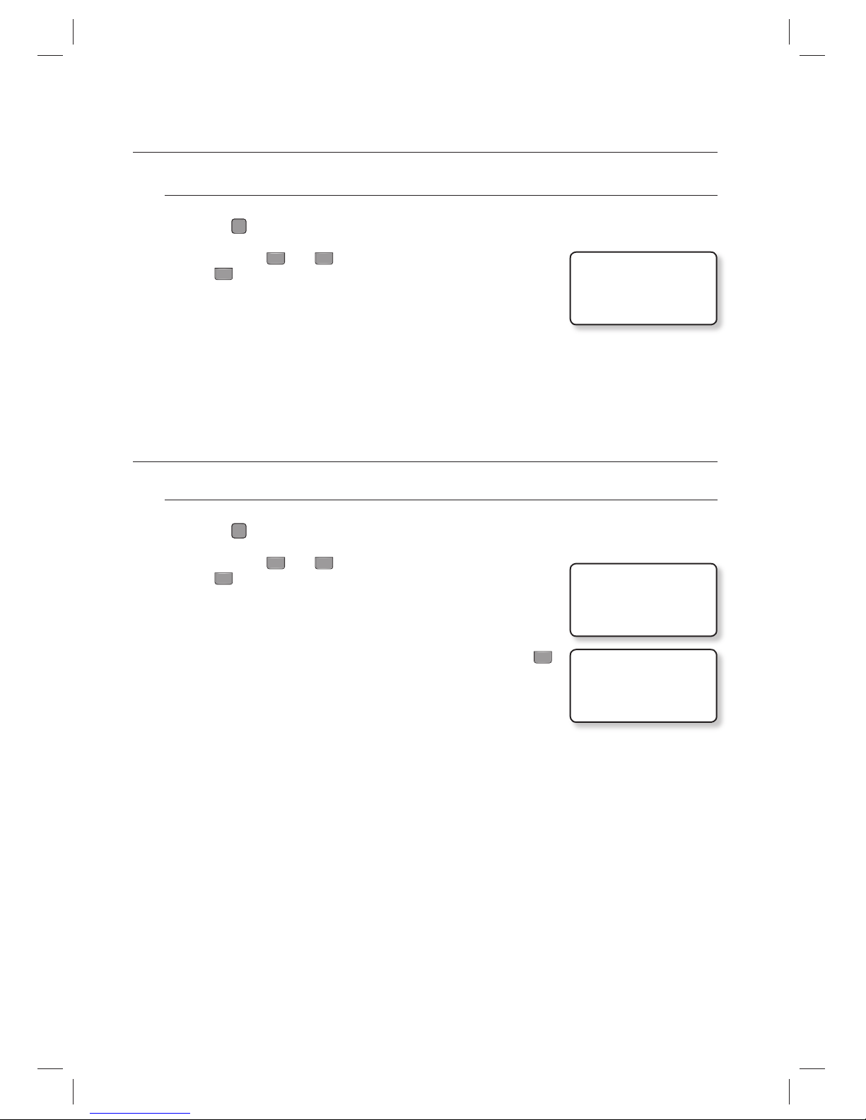
52_ I/O time setup
I/O time setup
Output Setup for Level 4 IDs Accessing READER #2
Press the
F
6
SETUP MENU button.
Use the buttons 4 and 6 to move to the RD2 ID OK LV4 item and
press
ENT
.
The operation time for each output is the same as in “Output Setup for
Level 1 IDs Accessing READER #2” above. (see page 51)
READER #2 ERROR OUTPUT SETUP
READER #2 ID Error Output Setup
Press the
F
6
SETUP MENU button.
Use the buttons 4 and 6 to move to the RD2 ID ERROR item and
press
ENT
.
You can make input when the prompt blinks.
If you enter ‘00’, no output setting is configured.
Use the keypad to enter the time for each output operation and press
ENT
.
DR : Door relay output
AR : Alarm relay output
T1 : TTL #1 output
T2 : TTL #2 output
BZ : Buzzer output
The output time differs, depending on the time unit.
If the time unit is 0.1 (second), you can specify the value between 0.0 and 9.8 second; if set to 1 (second), you can
specify between 0 and 98 seconds.
For the time unit, refer to the ‘Time Unit Setup’ under the advanced setup. (see page 54)
If you enter 99 for the value, the product stays in output mode until you change the setting regardless of the time
unit.
1.
2.
•
1.
2.
3.
•
•
M
11.RD2 ID OK LV4
DR AR T1 T2 BZ
05 00 00 00 00
12.RD2 ID ERROR
DR AR T1 T2 BZ
00 03 00 00 00
12.RD2 ID ERROR
DR AR T1 T2 BZ
_0 03 00 00 00
Page 53
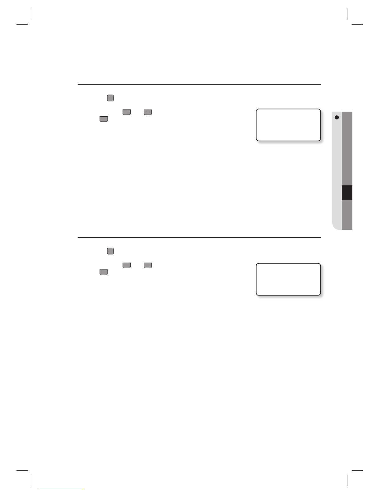
English English _ 53
I/O TIME SETUP
READER #2 Time Schedule Error Output Setup
Press the
F
6
SETUP MENU button.
Use the buttons 4 and 6 to move to the RD2 T/S ERROR item and
press
ENT
.
The operation time for each output is the same as in “READER #2 ID Error
Output Setup” above. (see page 52)
Time schedule must be confi gured before. (See Page 55 for “Time Schedule Setup”.)
READER #2 Antipassback Error Output Setup
Press the
F
6
SETUP MENU button.
Use the buttons 4 and 6 to move to the RD2 APB ERROR item and
press
ENT
.
The operation time for each output is the same as in “READER #2 ID Error
Output Setup” above. (see page 52)
APB mode must be enabled before. (See Page 55 for “AntiPassBack Mode”.)
1.
2.
•
M
1.
2.
•
M
13.RD2 T/S ERROR
DR AR T1 T2 BZ
00 03 00 00 00
14.RD2 APB ERROR
DR AR T1 T2 BZ
00 03 00 00 00
Page 54
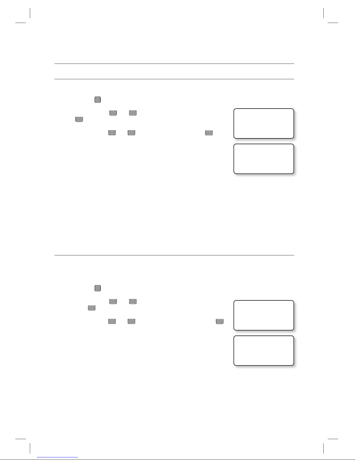
54_ advanced setup
advanced setup
TIME UNIT SETUP
You can use this menu to specify the time unit.
Press the
F
2
SETUP MENU button.
Use the buttons 4 and 6 to move to the TIME UNIT item and press
ENT
.
Use the buttons 4 and 6 to specify the time unit and press
ENT
.
UNIT: 1SEC : The output time is calculated by the second in the I/O
setup.
UNIT: 0.1SEC : The output time is calculated by the 1/10 second
(100ms) in the I/O setup.
The default is set to “UNIT: 1SEC”.
see the following example
If you want to keep the Door Relay (Relay #1, DR) active for 3 seconds, follow the steps below:
- Set the time unit to 1 second.
- Set the Door Relay (DR) output time to “03”.
If you want to keep the Door Relay (Relay # 1, DR) active for o.5 second, follow the steps below:
- Set the time unit to 0.1 second.
- Set the Door Relay (DR) output time to “05”.
Your change to the time unit will affect all I/O time settings.
OUTPUT TIME SCHEDULE+ID
The Output T/S+ID feature is used, in particular, in opening the door for a specifi ed time period in a specifi c time schedule.
However, you can set it not to open the door after the specifi ed time unless a user entry (i.e., entering the ID) is attempted.
The closing time is, of course, the end point of the specifi ed time period.
Press the
F
2
SETUP MENU button.
Use the buttons 4 and 6 to move to the OUTPUT T/S + ID item and
press
ENT
.
Use the buttons 4 and 6 to select USE or NOT USE, and press
ENT
.
NOT USE : The entrance door is set to be open when it reaches the
specifi ed time in the time schedule code.
USE : The entrance door will be not open when it reaches the specified
time in the time schedule code, but is open when a registered
user is authenticated.
Time schedule must be confi gured before. (See Page 59 for “Time Schedule Setup”.)
The Output T/S + ID is set to “NOT USE” by default.
1.
2.
3.
•
M
1.
2.
3.
•
M
3.TIME UNIT
J UNIT: 1SEC
3.TIME UNIT
J UNIT: 0.1SEC
4.OUTPUT T/S + ID
J NOT USE
4.OUTPUT T/S + ID
J USE
Page 55
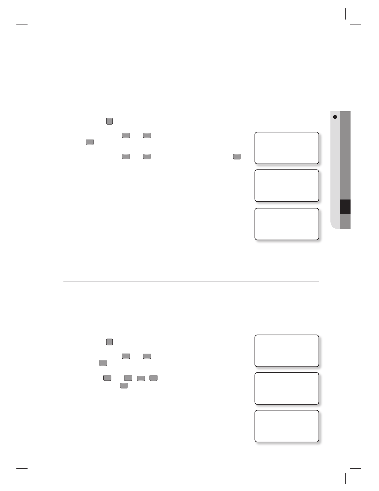
English English _ 55
ADVANCED SETUP
ANTIPASSBACK MODE
Antipassback mode is used to prevent an identical user from entering or exiting the door twice or more consecutively. This
mode is available only with an Exit reader dedicated to detecting exits, which is not available in a system that is solely using
the Exit button to exit the door.
Press the
F
2
SETUP MENU button.
Use the buttons 4 and 6 to move to the APB MODE item and press
ENT
.
Use the buttons
4
and 6 to select a desired mode and press
ENT
.
NOT USE : The Antipassback mode is disabled.
USE :
The Anti-Pass Back mode is enabled.
ALL CLEAR! :
If entrance or exit is not allowed because of violation of the
Anti-Pass Back rules, this will reset the status and resume
allowing users to enter or exit the door.
The Antipass back mode is set to “NOT USE” by default.
You can confi gure the APB error outputs for each reader on the entrance and exit. (Refer to “Antipassback Error
Output Setup” at pages 50 and 53.)
TIME SCHEDULE SETUP
You can set a total of 10 Time Schedule codes. The default code is “00”, which is used to allow unlimited access.
Each Time Schedule code has 8 programmable days (Sunday through Saturday, and a holiday), each of which has 5 time
intervals.
You can check information such as Time Schedule code, day of the week, time interval and current Time Schedule setting.
A holiday in the Time Schedule is linked to a holiday schedule code.
The Time Schedule is based on 24-hour format and therefore “00:00” and “24:00” refer to the same time.
Press the
F
4
SETUP MENU button.
Use the buttons 4 and 6 to move to the TIME SCHEDULE item and
press
ENT
.
Use the 4 and 6, 2, 8 buttons to specify the interval, day and
code and press
ENT
.
T/S CODE : Time Schedule Code 01~10
Weekly : 8 days (HOL,SUN,MON,TUE,WED,THU,FRI,SAT)
INTERVAL : Time interval 1~5
00:00 – 00:00 : hour : min
1.
2.
3.
•
M
1.
2.
3.
•
5.APB MODE
J NOT USE
5.APB MODE
J USE
5.APB MODE
J ALL CLEAR!
1.TIME SCHEDULE
T/S CODE: 01 HOL
INTERVAL: 1
00:00 – 00:00
1.TIME SCHEDULE
T/S CODE: 10 SAT
INTERVAL: 1
00:00 – 00:00
1.TIME SCHEDULE
T/S CODE: 01 SUN
INTERVAL: 5
12:10 – 15:59
Page 56
56_ advanced setup
advanced setup
Use the numeric buttons to enter start or end time in 8 digits.
If an entry is invalid, the “INVALID NUMBER” message will appear.
Repeat steps 3 through 4 above to set other time schedules.
Upon completion of all time schedules, press
ESC
to exit from the menu.
HOLIDAY SETUP
This feature allows you to set holidays of your choice.
Each of 10 Holiday Codes can have up to 100 programmable holidays.
You can view holiday information set on each holiday code.
Press the
F
4
SETUP MENU button.
Use the buttons 4 and 6 to move to HOLIDAY SET and press
ENT
.
Use the 4, 6, 2 and 8 buttons to select HOLIDAY CODE, and
DAY NO and press
ENT
.
HOLIDAY CODE : 01~10
DAY NO. : 001~100
Use the numeric buttons to enter 4-digit month/day and press
ENT
.
If the entry is incorrect, the “INVALID NUMBER” message will appear.
Repeat steps 3 through 4 to set other holiday schedule codes.
Upon completion of all holiday schedule settings, exit the menu by
pressing
ESC
.
4.
•
5.
6.
1.
2.
3.
•
4.
•
5.
6.
1.TIME SCHEDULE
T/S CODE: 01 HOL
INTERVAL: 1
00:00 – 00:00
2.HOLIDAY SET
HOLIDAY CODE: 01
DAY NO. : 001
00/00
2.HOLIDAY SET
HOLIDAY CODE: 01
DAY NO. : 100
01/25
2.HOLIDAY SET
HOLIDAY CODE: 10
DAY NO. : 050
12/31
2.HOLIDAY SET
HOLIDAY CODE: 01
DAY NO. : 001
00/00
Page 57
English English _ 57
ADVANCED SETUP
HOLIDAY CODE SETUP
The Holiday Code setting allows you to link a Holiday Schedule to a Time Schedule.. A Time Schedule has 5 Time
Intervals for holidays and the Time Intervals are applied only to the dates of this Holiday Schedule.
The Holiday Code ‘00’ means no holiday codes are applied to the Time Schedule.
Use the buttons
4
and 6 to scroll up and down from the T/S Code 01 to 10. And, press
ENT
to enter a 2-digit
Holiday Schedule Code. You can also press
ENT
to store the Holiday Index to the memory.
Press the
F
4
SETUP MENU button.
Use the buttons 4 and 6 to move to HOLIDAY CODE and press
ENT
.
Use the buttons 4 and 6 to select Time Schedule and press
ENT
.
T/S (Time Schedule) CODE : 01~10
Use the numeric buttons to enter 2-digit holiday code.
HOLIDAY CODE : 01~10
If the entry is invalid, the “INVALID NUMBER” message will appear.
Repeat steps 3 through 4 above to set other time schedules.
Upon completion of all holiday code settings, exit the menu by pressing
ESC
.
1.
2.
3.
•
4.
•
•
5.
6.
3.HOLIDAY CODE
T/S CODE: 01 I
HOLIDAY CODE: 00
3.HOLIDAY CODE
T/S CODE: 01 I
HOLIDAY CODE: 00
3.HOLIDAY CODE
T/S CODE: 10 I
HOLIDAY CODE: 00
3.HOLIDAY CODE
T/S CODE: 01 I
HOLIDAY CODE: 10
Page 58
58_ advanced setup
advanced setup
READER MODE TIME SCHEDULE
READER #1 MODE TIME SCHEDULE
There are 3 reader modes (in READER #1) including ID Mode, ID+F/P Mode and ID+PW+F/P Mode. Unless
otherwise set specifi cally, all registered users should be verifi ed according to the reader mode in use. However
you may allow entry with card only during a certain time interval for all users.
For example, suppose you want to access the door by only presenting a card from 09:00 to 17:00 and use the
Fingerprint Verifi cation method for the rest of the time. And, you can do so by setting [READER1 MODE
SETTING] to ID+F/P Mode which will be general operation mode, and program a T/S Code “01” so that it can
include a time period between 09:00 and 17:00 for card access. And, link the programmed Time Schedule
Code 01 to the READER1 MODE Time Schedule setting.
Press the
F
4
SETUP MENU button.
Use the buttons 4 and 6 to move to the RD1 MODE T/S item and
press
ENT
.
Use the numeric buttons to enter 2-digit code and press
ENT
.
T/S(Time Schedule) CODE : 00~10
If the entry is incorrect, the “INVALID NUMBER” message will appear.
The T/S Code “00” indicates no Time Schedule is to be applied.
READER #2 Mode Time Schedule
There are 2 reader modes (in READER #2) including ID Mode and ID+P/W Mode. Unless otherwise specifi ed, all
registered users should be authenticated to the reader mode in use. However you may allow entry with card
only during a certain time interval for all users.
For example, suppose you want to access the door by only presenting a card from 09:00 to 17:00 and use the
Fingerprint Verifi cation method for the rest of the time. And, you can do so by setting [READER2 MODE
SETTING] to ID+P/W Mode which will be general operation mode, and program a T/S Code “01” so that it can
include a time period between 09:00 and 17:00 for card access. And, link the programmed Time Schedule
Code 01 to the READER2 MODE Time Schedule setting.
Press the
F
4
SETUP MENU button.
Use the buttons 4 and 6 to move to RD2 MODE T/S and press
ENT
.
It can be confi gured in the same way as READER#1 Mode Time Schedule
setting.
1.
2.
3.
•
•
•
1.
2.
•
5.RD2 MODE I T/S
00
4.RD1 MODE I T/S
00
4.RD1 MODE I T/S
10
Page 59
English English _ 59
ADVANCED SETUP
6.VOICE I T/S
00
6.VOICE I T/S
10
VOICE MESSAGE TIME SCHEDULE
The Voice Message Time Schedule function allows you to apply time schedules to the voice message output and mute
them at other times.
To apply a time schedule code, enter the time schedule code you want. Within the time range assigned by the time
schedule, voice messages will be played while at other times, they will not be played.
Using this feature, for example, you can confi gure the unit to play voice messages in the daytime and mute them at night.
Press the
F
4
SETUP MENU button.
Use the buttons 4 and 6 to move to the VOICE T/S and
press
ENT
.
Use the numeric buttons to enter 2-digit code and press
ENT
.
T/S(Time Schedule) CODE : 00~10
If the entry is incorrect, the “INVALID NUMBER” message will appear.
The T/S Code 00 indicates no Time Schedule is to be applied.
OUTPUT TIME SCHEDULE SETUP
You can link a Time Schedule Code to each output. The default Time Schedule Code for every output is “00”, which
means no Time Schedule is applied to them. Changing these settings can be very useful when you want to leave the
door open during a certain time period.
Press the
F
5
SETUP MENU button.
Use the buttons 4 and 6 to move to OUTPUT T/S and press
ENT
.
Use the numeric buttons to enter 2-digit code for each item and press
ENT
.
T/S(Time Schedule) CODE : 00~10
DR : Door Relay Output T/S code
AR : Alarm Relay Output T/S code
T1 : TTL#1 Output T/S code
T2 : TTL#2 Output T/S code
BZ : Buzzer Output T/S code
If the entry is incorrect, the “INVALID NUMBER” message will appear.
The T/S Code ‘00’ means no Time Schedules are to be applied.
1.
2.
3.
•
•
•
1.
2.
3.
•
•
•
10.OUTPUT T/S
DR AR T1 T2 BZ
00 00 00 00 00
10.OUTPUT T/S
DR AR T1 T2 BZ
10 00 01 00 00
Page 60
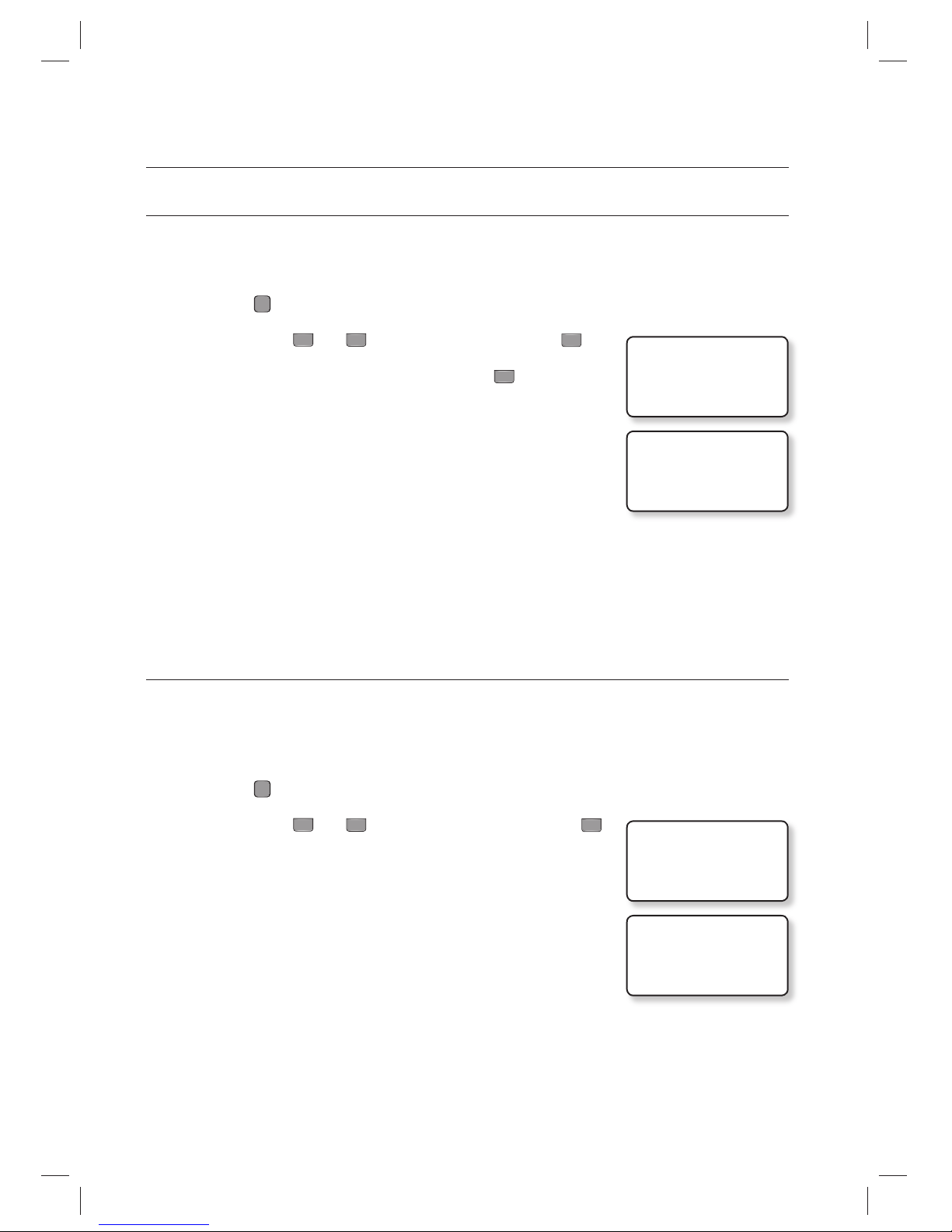
60_ advanced setup
advanced setup
INPUT TIME SCHEDULE SETUP
You can assign a Time Schedule Code to each input to activate the input only during that period. The default Time
Schedule Code for every input is “00”, which means no Time Schedule is applied to them. Changing these settings can
be very useful when you want to activate PIR sensor during a certain period of time.
Press the
F
5
SETUP MENU button.
Use the buttons 4 and 6 to move to INPUT T/S and press
ENT
.
Use the numeric buttons to enter 2-digit code and press
ENT
.
T/S(Time Schedule) CODE : 00~10
EX : EXIT Button Input T/S Code
DC : Door Contact Sensor Input T/S Code
I1 : Aux Input#1 T/S Code
I2 : Aux Input#2 T/S Code
TP : Tamper Switch Input T/S Code
If the entry is incorrect, the “INVALID NUMBER” message will appear.
The T/S Code ‘00’ means no Time Schedules are to be applied.
INPUT CUT OFF CHECK SETUP
You can choose whether or not to check the connection cutoff of each input port. The default setting is “00”. To enable
the cut off check function, change the setting to “01”.
In case of cut off detected at the input while the cut off check enabled, the corresponding output signal is given as per
“Cut Off Output Setup”. (See Page 46.)
Press the
F
5
SETUP MENU button.
Use the buttons 4 and 6 to move to CUT OFF SET and press
ENT
.
Use the numeric buttons to enter “00” or “01” for each input.
00 : The Input Cut Off check function is disabled.
01 : The Input Cut Off check function is enabled.
EX : Whether to use EXIT Button input cut off check.
DC : Whether to use Door Contact Sensor input cut off check.
I1 : Whether to use Aux Input #1 input cut off check.
I2 : Whether to use Aux Input #2 input cut off check.
TP : Whether to use Tamper Switch input cut off check.
If the entry is incorrect, the “INVALID NUMBER” message will appear.
Before enabling this function, a 2.2KΩ resistor should be connected between the input wire and the GND.
1.
2.
3.
•
•
•
1.
2.
3.
•
•
•
M
12. CUT OFF SET
EX DC I1 I2 TP
00 00 00 00 00
12.CUT OFF SET
EX DC I1 I2 TP
01 00 00 00 00
11. INPUT T/S
EX DC I1 I2 TP
00 00 00 00 00
11. INPUT T/S
EX DC I1 I2 TP
10 00 02 00 00
Page 61
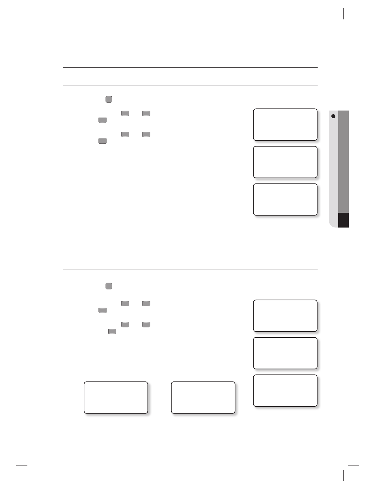
English English _ 61
ADDITIONAL FEATURES
additional features
EVENT MEMORY SETUP
Press the
F
2
SETUP MENU button.
Use the buttons 4 and 6 to move to EVENT MEMORY and
press
ENT
.
Use the buttons
4
and 6 to select either USE or NOT USE and
press
ENT
.
USE : When the event memory is full, it gives out an error message and
maintains all events stored in the memory.
NOT USE : Even when the event memory is full, it does not give out
an error message. In this case the last event saved in the
memory is replaced with the next new one. Select ‘NOT
USE’ for standalone use (only for entry access exclusively).
The default setting is “USE”.
ID DISPLAY
Press the
F
2
SETUP MENU button.
Use the buttons 4 and 6 to move to the ID DISPLAY item and
press
ENT
.
Use the buttons 4 and 6 to select MESSAGE or ID + MESSAGE
and press
ENT
.
MESSAGE : Instead of a text message and the user ID, the text message
of “********” will appear on the screen.
ID + MESSAGE : The User ID along with a text message will appear on the
screen.
ВВВВВВВВ
ACCESS GRANTED!
MYID
01/01 16:25 :07
<MESSAGE> <ID + MESSAGE>
12345678
ACCESS GRANTED!
MYID
01/01 16:25 :07
The “MYID” in the picture is a user name which will be displayed if the ID and name were registered using the
provided application software.
(See Page 26 for “Name Display”.)
1.
2.
3.
•
M
1.
2.
3.
•
•
1.EVENT MEMORY
NOT USE
1.EVENT MEMORY
J NOT USE
1.EVENT MEMORY
J USE
2. ID DISPLAY
MESSAGE
2.ID DISPLAY
J MESSAGE
2.ID DISPLAY
J ID + MESSAGE
Page 62
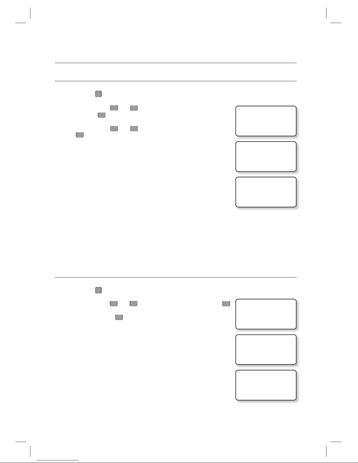
62_ additional features
additional features
WIEGAND OUTPUT SETUP
Press the
F
2
SETUP MENU button.
Use the buttons 4 and 6 to move to the WIEGAND OUTPUT item
and press
ENT
.
Use the buttons
4
and 6 to select either USE or NOT USE and press
ENT
.
USE : It sends 26 bit Wiegand Output (34 bit for SSA-S30X1 series)
through two TTL output ports (TTL OUT #1, TTL OUT #2), which
can be used as a reader in connection with other controller.
NOT USE : This product cannot be used as a reader.
When it is set to ‘USE’, the TTL #1 and TTL #2 outputs are disabled except for WIEGAND Outputs.
VOICE VOLUME SETUP
Press the
F
3
SETUP MENU button.
Use the buttons 4 and 6 to move to VOICE VOLUME and press
ENT
When done, press
ENT
to save your settings.
You can adjust the volume of the voice in 5 levels from 0 (mute) to 4
(maximum)
Adjust the volume level to “0” to disable voice output.
If you enter a value higher than ‘5’, the “INVALID NUMBER” message appears
and the volume stays at the previous setting.
1.
2.
3.
•
M
1.
2.
3.
•
M
7. WIEGAND OUTPUT
NOT USE
7. WIEGAND OUTPUT
J NOT USE
7. WIEGAND OUTPUT
J USE
1.VOICE VOLUME
VOLUME : 0
1.VOICE VOLUME
VOLUME : _
1.VOICE VOLUME
VOLUME : _
Page 63
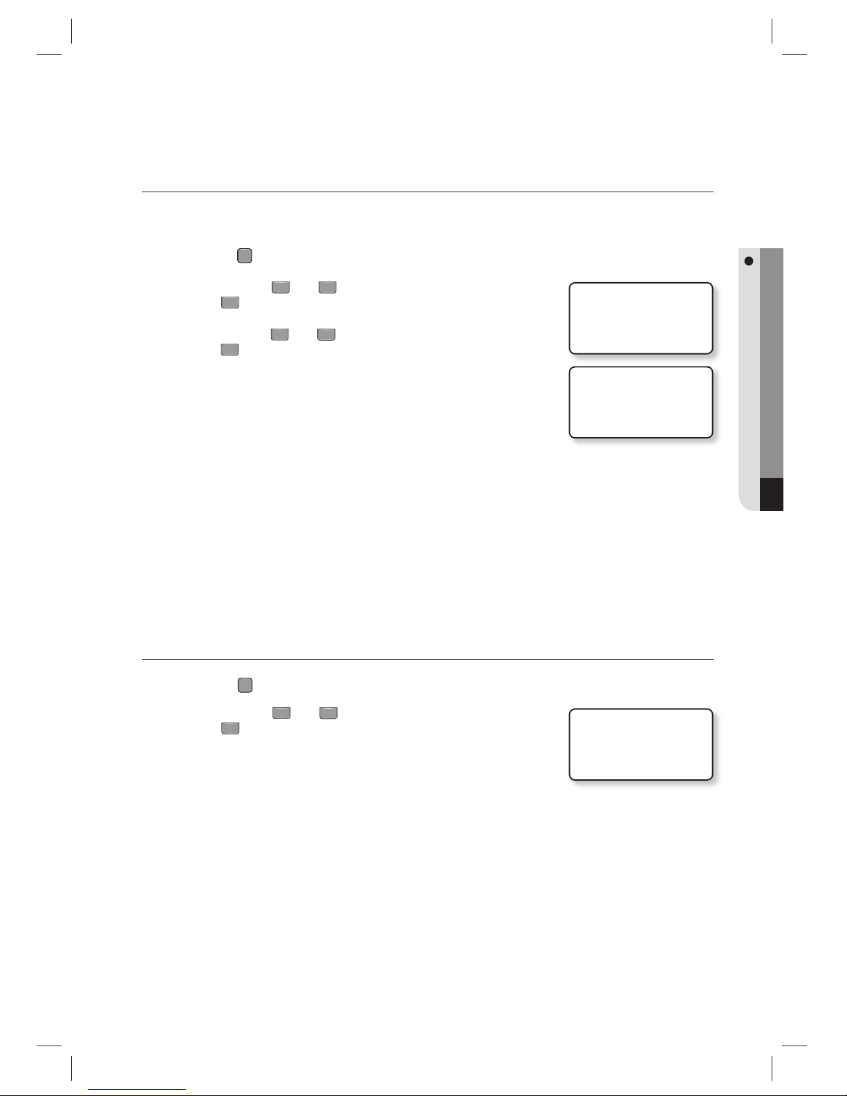
English English _ 63
ADDITIONAL FEATURES
ONE TIME READ
If the menu is set to “USE”, the card authentication will not take place for the next 30 seconds after an instance of
authenticating a registered card.
Press the
F
3
SETUP MENU button.
Use the buttons 4 and 6 to move to ONE TIME READ and
press
ENT
.
Use the buttons 4 and 6 to select either USE or NOT USE and
press
ENT
.
USE : The card authentication will not take place for 30 seconds after an
instance of authenticating a registered card.
For unregistered cards, the authentication process will be
attempted repeatedly.
When another registered card is successfully authenticated within
30 seconds from the first normal authentication by a registered
card, it is possible to authenticate the first card again not requiring
the time lag of 30 seconds.
NOT USE : Continuous re-authentication of a registered card is enabled.
The default setting for One Time Read is “NOT USE”.
VERSION CHECK
Press the
F
9
SETUP MENU button.
Use the buttons 4 and 6 to move to FIRMWARE VER. and
press
ENT
.
The fi rmware version of the unit is displayed.
1.
2.
3.
•
M
1.
2.
3.
4.ONE TIME READ
NOT USE
4.ONE TIME READ
JNOT USE
1.FIRMWARE VER.
SSA-S3010
v0.50_090803
Page 64
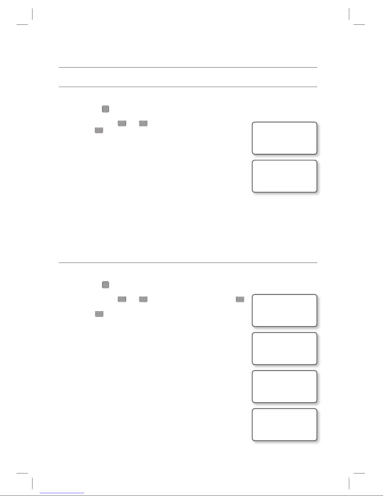
64_ additional features
additional features
INPUT TEST
This feature allows you to test settings for each input.
Press the
F
9
SETUP MENU button.
Use the buttons 4 and 6 to move to the INPUT TEST item and
press
ENT
.
The corresponding value changes upon input.
0 : It indicates that the input port is open circuit.
1 : It indicates that the input port is short circuited at the earth-grounding
level.
2 : It indicates that the corresponding port is not connected.
EX : Exit Button Input
DC : Door Contact Sensor Input
I1 : Auxiliary Input #1
I2 : Auxiliary Input #2
TP : Tamper Switch Input
OUTPUT TEST
This feature allows you to test settings for each output.
Press the
F
9
SETUP MENU button.
Use the buttons 4 and 6 to move to OUTPUT TEST and press
ENT
Press
ENT
to turn ON/OFF the DOOR RELAY, ALARM RELAY, TTL#1,
TTL#2, BUZZER in sequence.
DOOR RELAY (ON/OFF)
ALARM RELAY (ON/OFF)
TTL#1 (ON/OFF)
TTL#2 (ON/OFF)
BUZZER (ON/OFF)
Press any key to move to the parent menu.
The fi rst two tests verify if the output relays (Door Relay and Alarm Relay) are
working properly. You can hear the mechanical sound of relay with a blinking
LED indicator.
The next two tests are to verify TTL#1 and TTL#2 outputs. Finally, the last test is
for an Internal Buzzer test. You can hear two beeps during the test.
1.
2.
3.
•
•
1.
2.
3.
•
4.
M
2.INPUT TEST
EX DC I1 I2 TP
2 2 2 2 0
2.INPUT TEST
EX DC I1 I2 TP
2 2 2 2 0
3.OUTPUT TEST
3.OUTPUT TEST
DOOR RELAY
ON
3.OUTPUT TEST
DOOR RELAY
OFF
PRESS ANY KEY…
Page 65
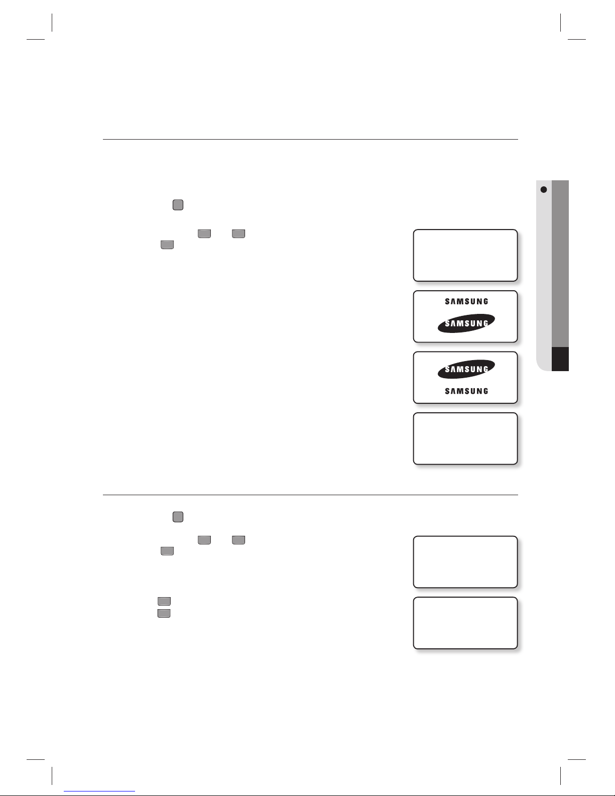
English English _ 65
ADDITIONAL FEATURES
LCD TEST
This feature allows you to test the LCD status. The SAMSUNG logo will appear rolling up and down. At this time you
can check any abnormality in the LCD.
Press the
F
9
SETUP MENU button.
Use the buttons 4 and 6 to move to the LCD TEST item and
press
ENT
.
Check the SAMSUNG logo.
The last date the fi rmware is amended and the version information is
displayed.
KEYPAD TEST
Press the
F
9
SETUP MENU button.
Use the buttons 4 and 6 to move to the KEYPAD TEST item and
press
ENT
.
When the Keypad Test screen appears, try to press each key one by one.
The depressed key will disappear from the screen.
¼ :
ESC
on the keypad
#
:
ENT
on the keypad
1.
2.
•
3.
1.
2.
3.
•
4.LCD TEST
LAST UPDATE
v0.50_090803
PRESS ANY KEY
5.KEYPAD TEST
123 F1 F2 F3
456 F4 F5 F6
789 F7 F8 F9
*0# F10 F11 F12
Page 66
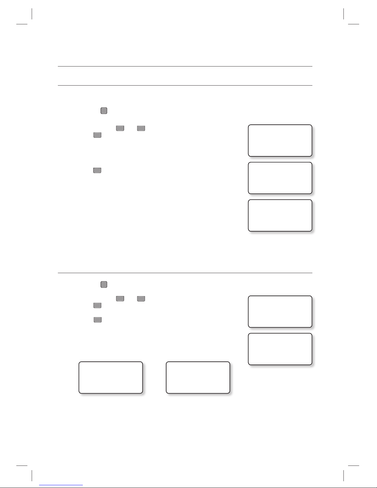
66_ additional features
additional features
READER TEST
This function allows you to test the internal (READER #1) and the external readers (READER #2).
Press the
F
9
SETUP MENU button.
Use the buttons 4 and 6 to move to the READER TEST item and
press
ENT
.
Place your card close to the reader. When the card is read successfully, the
reader number with the 8-digit card number will be displayed on the screen.
Press
ESC
to move to the parent menu.
MEMORY TEST
Press the
F
9
SETUP MENU button.
Use the buttons 4 and 6 to move to the MEMORY TEST item and
press
ENT
.
Press
ENT
to start the test.
Please see the pictures below for the screens when the test has succeeded
and failed.
TEST PASSED!!!
PRESS ANY KEY…
<If the test has succeeded > <If the test has failed>
TEST FAILED!!!
PRESS ANY KEY…
Press any key to move to the parent menu.
If the Data Memory has a problem, the “TEST FAILED” message will be displayed on the screen.
If this is the case, contact the nearest Service Center for technical support.
1.
2.
3.
4.
1.
2.
3.
4.
5.
J
6.READER TEST
SCANNING…
6.READER TEST
READER #1
25500363
6.READER TEST
7.MEMORY TEST
RAM TESTING…
Page 67
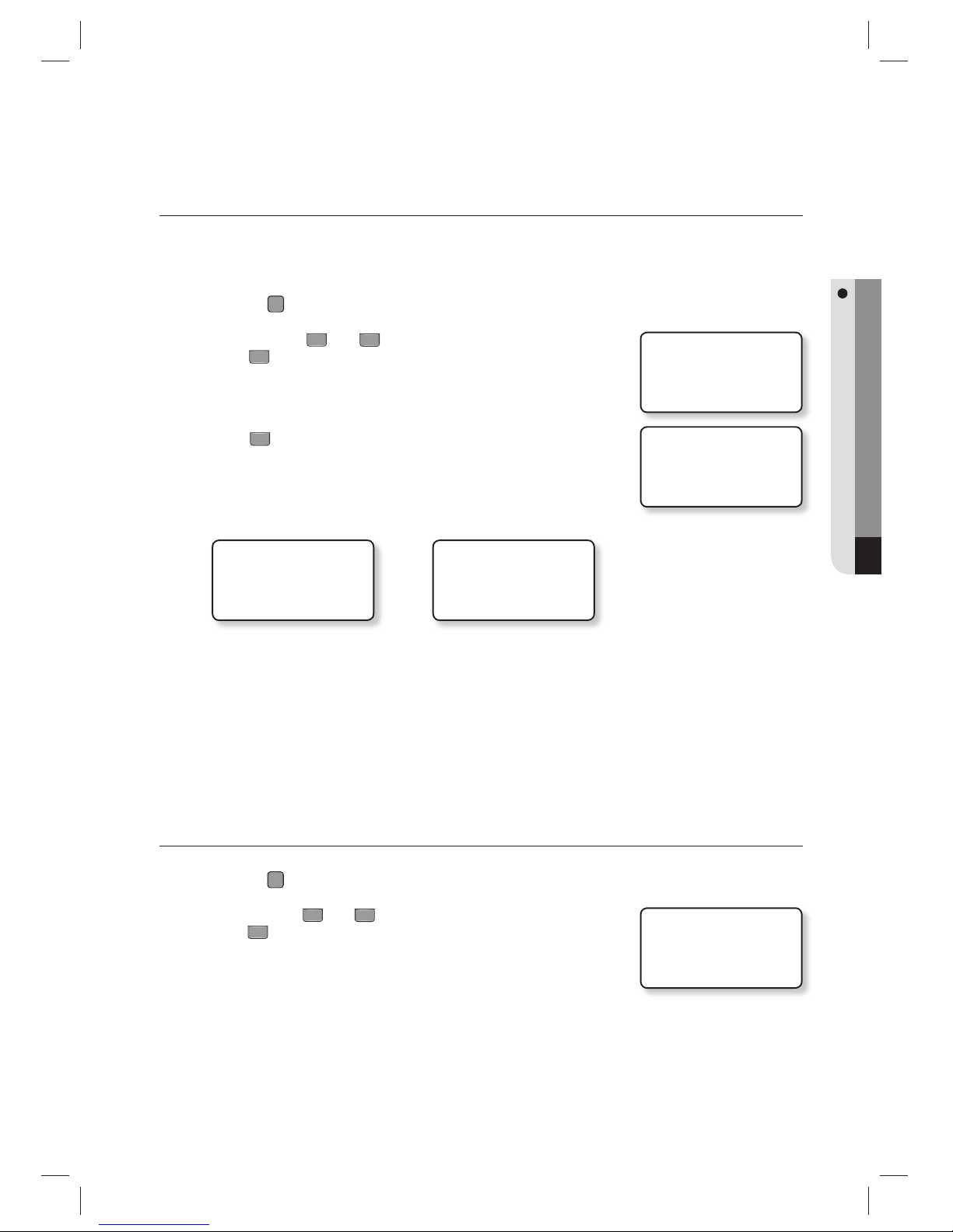
English English _ 67
ADDITIONAL FEATURES
COMMUNICATION TEST
Before executing this test, remember to connect the RS-232 TX wire (Black wire with White stripe) and the RS-232 RX
wire (Red wire with White stripe) together. This is to test on the built-in communication chip, not on the communication
with the computer.
Press the
F
9
SETUP MENU button.
Use the buttons 4 and 6 to move to the COMM TEST item and
press
ENT
.
TX DATA : Transmit Data
RX DATA : Receive Data
Press
ENT
to start the test.
Please see the pictures below for the screens when the test has succeeded
and failed.
TEST PASSED!!!
PRESS ANY KEY…
< If the test has succeeded > < If the test has failed >
TEST FAILED!!!
PRESS ANY KEY…
Press any key to move to the parent menu.
If the communication is malfunctioning, the “TEST FAILED!!!” message will be displayed.
If this is the case, contact the nearest Service Center for technical support.
FINGERPRINT MODULE VERSION CHECK
Press the
F10
SETUP MENU button.
Use the buttons
4
and 6 to move to the MODULE VERSION item and
press
ENT
.
The version of the fi ngerprint module will be shown.
1.
2.
•
3.
4.
5.
M
1.
2.
•
8.COMM TEST
TX DATA = 0
RX DATA = 0
5.MODULE VERSION
V1.71
Page 68
68_ additional features
additional features
INPUT TYPE SETUP
Either one of NO(00) or NC(01) is available for the input type.
The default setting is ‘00(Normal Open)’.
Press the
F
5
SETUP MENU button.
Use the buttons 4 and 6 to move to the INPUT TYPE item and
press
ENT
.
You can make input when the prompt blinks.
Use the numeric buttons to enter ‘00’ or ‘01’ for operation type for each
input and press
ENT
.
NO: Normal Open, open is normal
NC :Normal Close, close is normal
EX : Exit Button
DC : Door Open Sensor
I 1 : Aux Input #1
I 2 : Aux Input #2
TP : Tamper Input
If values other than ‘00’ or ‘01’ are entered, the error message of “INVALID NUMBER” will appear and the values you entered will
not be saved.
Check the operation type of the input device that is connected to the input port. If the operation type is set incorrectly, it will cause
unintended result.
1.
2.
3.
•
M
13.INPUT TYPE
00: NO, 01: NC
EX DC I1 I2 TP
00 00 00 00 00
13.INPUT TYPE
00: NO, 01: NC
EX DC I1 I2 TP
_0 00 00 00 00
Page 69
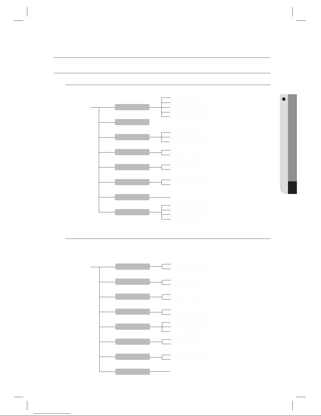
English English _ 69
OTHER INFORMATION
other information
MENU STRUCTURE
000~255
9600
19200
38400
57600
NOT USE
USE
NOT USE
USE
FRANÇAIS
DEUTSCH
ESPAÑOL
ENGLISH
ID ONLY
ID+F/P(PW)
ID+P/W+F/P
ID ONLY
ID+PW
F1 button
LANGUAGE
SET DATE/ TIME
READER #1 MODE
READER #2 MODE
RD#1 KEY INPUT
RD#2 KEY INPUT
COMM ADDR SET
BAUD RATE
00~99
NOT USE
USE
NOT USE
USE
NOT USE
USE
ALL CLEAR!
UNIT : 1 SEC
UNIT : 0.1 SEC
MESSAGE
ID+ MESSAGE
USE
NOT USE
NOT USE
USE
F2 button
EVENT MEMORY
ID DISPLAY
TIME UNIT
OUTPUT T/S + ID
APB MODE
DURESS MODE
WIEGAND OUTPUT
OPEN ALR TIME
Menu Structure of the [F1] button
You can set Language, Date/Time and READER modes.
Menu Structure of the [F2] button
You can set Event Memory, ID Display, Time Unit Setup, Output Time Schedule + ID, Antipassback Mode,
Duress Mode, WIEGAND Output, and Door Open Timeout Alarm.
ITALIANO
Page 70
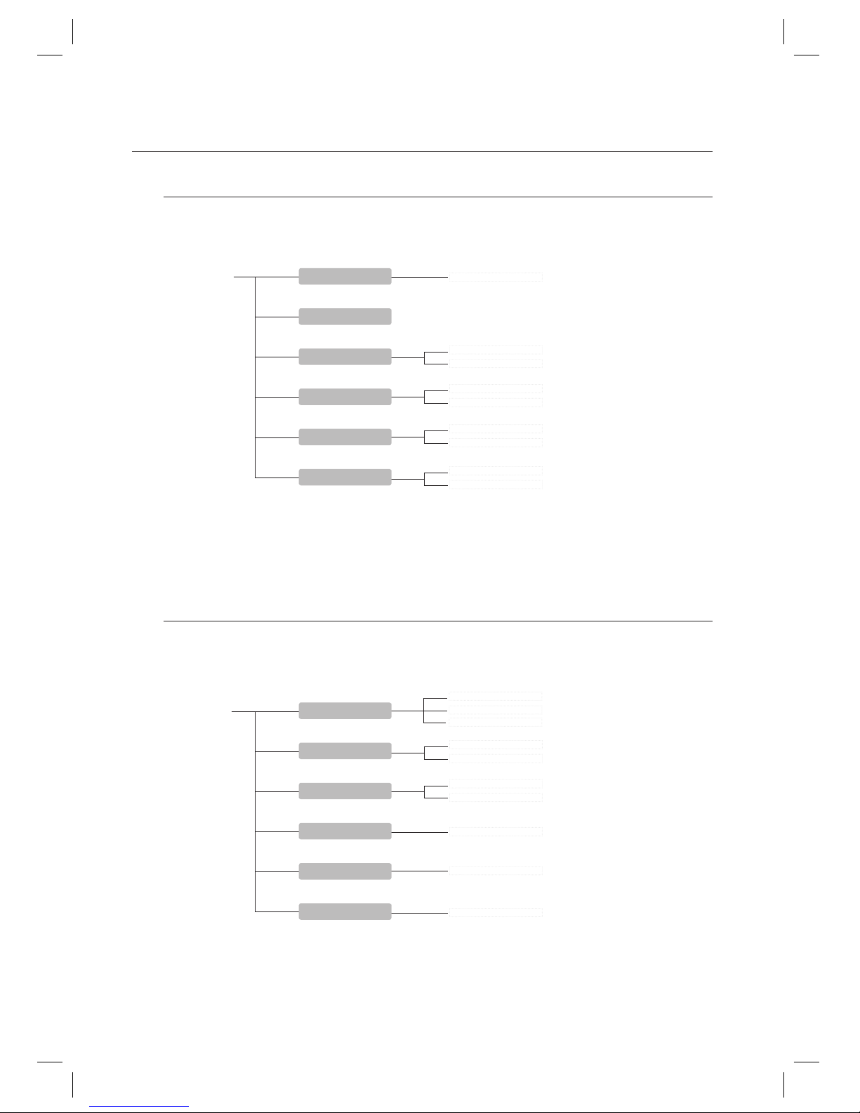
70_ other information
other information
NOT USE
USE
NOT USE
USE
0 (MUTE) ~ 4 (MAXIMUM)
10,000
20,000
NOT USE
USE
F3 button
VOICE VOLUME
ARM/DISARM SET
TWO MEN MODE
ONE TIME READ
MAX USER SETUP
NAME DISPLAY
T/S CODE : 01~10
T/S CODE : 01~10
T/S CODE : 01~10
T/S CODE : 01~10
Weekly
INTERVAL : 1~5
T/S CODE : 01~10
HOLIDAY CODE : 01~10
HOLIDAY CODE : 01~10
DAY NO. : 001~100
F4 button
TIME SCHEDULE
HOLIDAY SET
HOLIDAY CODE
RD1 MODE T/S
RD2 MODE T/S
VOICE T/S
Menu Structure of the [F3] button
You can set Voice Volume, Arm/Disarm, Two Men Operation, One Time Read, Number of Users, and Name
Display.
Menu Structure of the [F4] button
You can set Time Schedule, Holiday, Holiday Code, READER #1 and #2 Mode Time Schedule, and Voice
Message Time Schedule.
Page 71

English English _ 71
OTHER INFORMATION
F5 button
EXIT BUTTON
DOOR CONTACT
AUX INPUT #1
AUX INPUT #2
TAMPER ALARM
CUT OFF ALARM
DURESS ALARM
ARM/DISARM OUT
DOOR TIME OUT
OUTPUT T/S
INPUT T/S
CUT OFF SET
INPUT TYPE
Menu Structure of the [F5] button
You can set Exit Key Output, Door Contact Sensor, Aux Input #1 and #2, Tamper Alarm Output, Cut Off
Output, Duress Alarm Output, Arm/Disarm Output, Door Open timeout Output, Input/Output Time Schedule,
Input Cut Off Check, and Input Type.
Page 72

72_ other information
other information
F6 button
RD1 ID OK LV1
RD1 ID OK LV2
RD1 ID OK LV3
RD1 ID OK LV4
RD1 ID ERROR
RD1 T/S ERROR
RD2 ID OK LV1
RD2 ID OK LV2
RD2 ID OK LV3
RD2 ID OK LV4
RD2 ID ERROR
RD2 T/S ERROR
RD2 APB ERROR
RD1 APB ERROR
Menu Structure of the [F6] button
You can set Output for Accessible levels for READER #1 and #2 ID, READER #1 and #2 ID Error Output,
READER #1 and #2 Time Schedule Error Output, READER #1 and #2 Antipassback Error Output.
Page 73
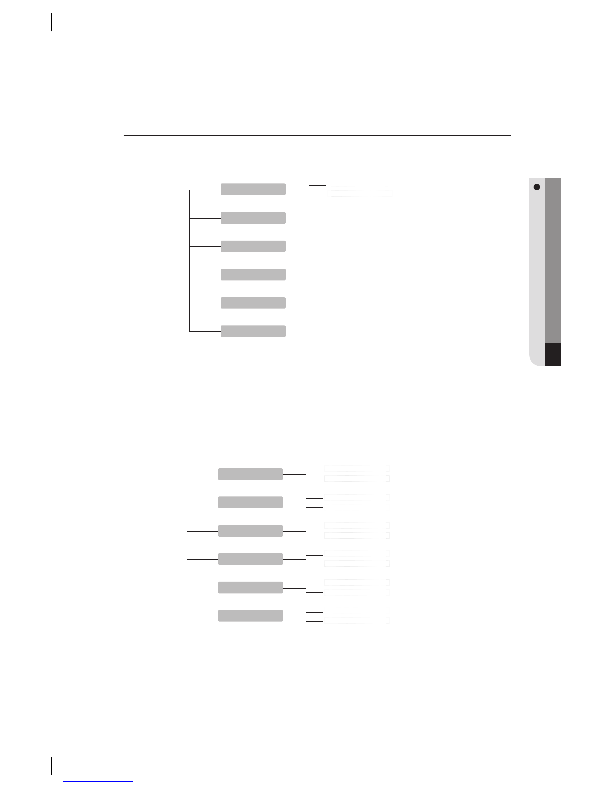
English English _ 73
OTHER INFORMATION
YES
NO
YES
NO
YES
NO
YES
NO
YES
NO
YES
NO
F8 button
SYSTEM INIT.
EVENT CLEAR
ALL ID CLEAR
MASTER ID CLR
T/S CLEAR
DEFAULT SET
CARD
PIN
F7 button
REGISTRATION
ID DELETE
ID LIST
MASTER ID REG
REG. ID COUNT
EVENT COUNT
Menu Structure of the [F7] button
You can register or delete IDs and register the master ID. You can also view the ID list, ID count and event
count.
Menu Structure of the [F8] button
You can initialize the master mode and delete the entire events, IDs, Master ID and Time Schedules.
Page 74
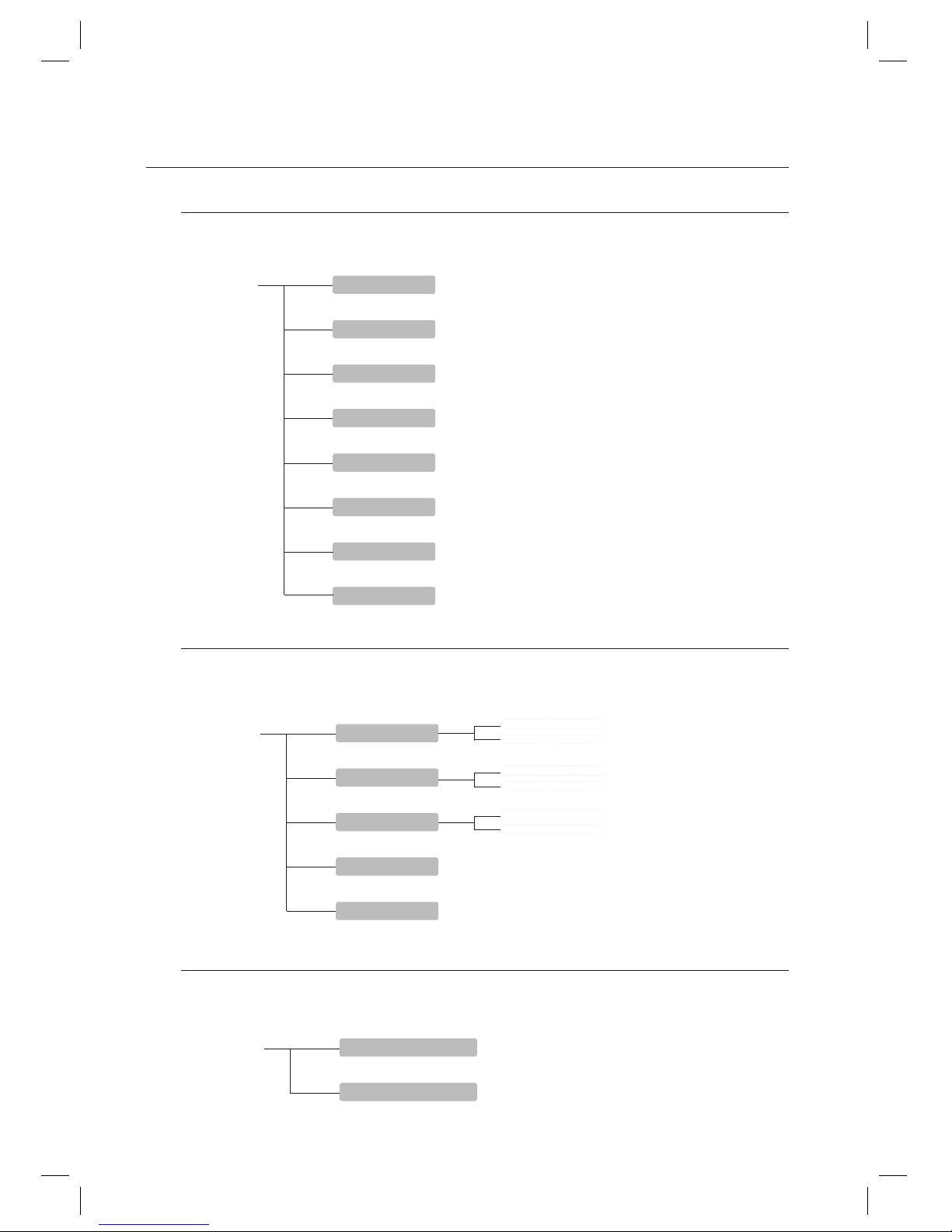
74_ other information
other information
F9 button
FIRMWARE VER.
INPUT TEST
OUTPUT TEST
LCD TEST
KEYPAD TEST
READER TEST
MEMORY TEST
COMM TEST
Menu Structure of the [F9] button
You can check the system version. You can also test the input, output, LCD, keypad, reader, memory and
communication status.
NOT USE
USE
NOT USE
USE
NOT USE
USE
F10 button
DUAL F/P MODE
ADAPTIVE MODE
IDENTIFICATION
FP REG. COUNT
MODULE VERSION
[Menu Structure of the [F10] button
You can set the Dual Fingerprint Mode and ID Modes, and check the number of registered fi ngerprints and the
fi ngerprint module version.
Menu Structure of the [F12] button
You can easily register or delete IDs without going through a complex setup procedure.
F12 button
(QUICK MODE) REGISTRATION
(QUICK MODE) ID DELETE
Page 75
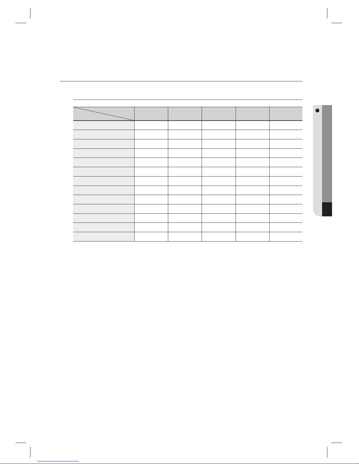
English English _ 75
OTHER INFORMATION
DEFAULT SETTINGS
Output Settings for Input Sources
Output
Input
Door Relay
(DR)
Alarm Relay
(AR)
TTL#1
(T1)
TTL#2
(T2)
Buzzer
(BZ)
[1] Exit Button
03 00 00 00 00
[2] Door Contact
00 99 00 00 00
[3] AUX Input #1
00 00 00 00 00
[4] AUX Input #2
00 00 00 00 00
[5] TAMPER Alarm
00 99 99 99 99
[6] Cut Off Alarm
00 00 00 00 00
[7] DURESS ALARM
00 00 00 00 00
[8] ARM/DISARM OUT
00 00 00 00 00
[9] Door Open Timeout
00 99 00 00 00
[10] Output Time Schedule
00 00 00 00 00
[11] Input Time Schedule
00 00 00 00 00
[12] Cut Off Check
00 00 00 00 00
[13] Input Type
00 00 00 00 00
Index No. [1] ~ [9]
The values indicate the operating time of each output for the input signal.
Index No. [10]
The values indicate the time schedule code (index) applied to each output.
Index No. [11]
The values indicate the input port ([1]Exit Button ~ [5]Tamper S/W).
Each value indicates the code of Time Schedule to be applied to the corresponding input port.
Index No. [12]
The values indicate whether or not to use the cut off check feature for each input.
(0 – Not Use, 1 – Use)
Index No. [13]
The values indicate whether the input type is NO(Normally Open) or NC(Normally Closed).
(0 – NO, 1 – NC)
1)
2)
3)
4)
5)
Page 76
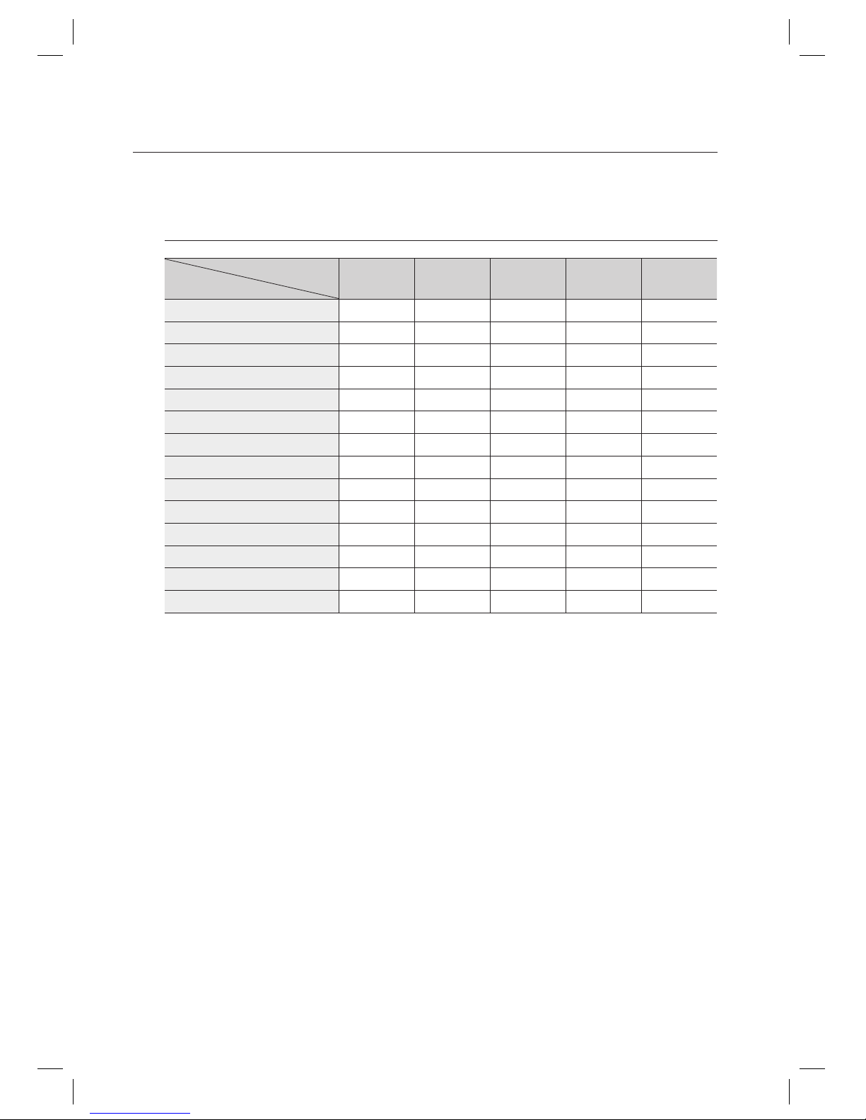
76_ other information
other information
Output Setting for Authentication
Output
Input
Door Relay
(DR)
Alarm Relay
(AR)
TTL#1
(T1)
TTL#2
(T2)
Buzzer
(BZ)
[1] Reader#1 ID OK LV1
03 00 00 00 00
[2] Reader#1 ID OK LV2
05 00 00 00 00
[3] Reader#1 ID OK LV3
05 00 00 00 00
[4] Reader#1 ID OK LV4
05 00 00 00 00
[5] Reader#1 ID Error
00 03 00 00 00
[6] Reader#1 T/S Error
00 03 00 00 00
[7] Reader#1 APB Error
00 03 00 00 00
[8] Reader#2 ID OK LV1
03 00 00 00 00
[9] Reader#2 ID OK LV2
05 00 00 00 00
[10] Reader#2 ID OK LV3
05 00 00 00 00
[11] Reader#2 ID OK LV4
05 00 00 00 00
[12] Reader#2 ID Error
00 03 00 00 00
[13] Reader#2 T/S Error
00 03 00 00 00
[14] Reader#2 APB Error
00 03 00 00 00
Index No. [1] ~ [14]
The values indicate the operating time of each output for the input signal.
1)
Page 77
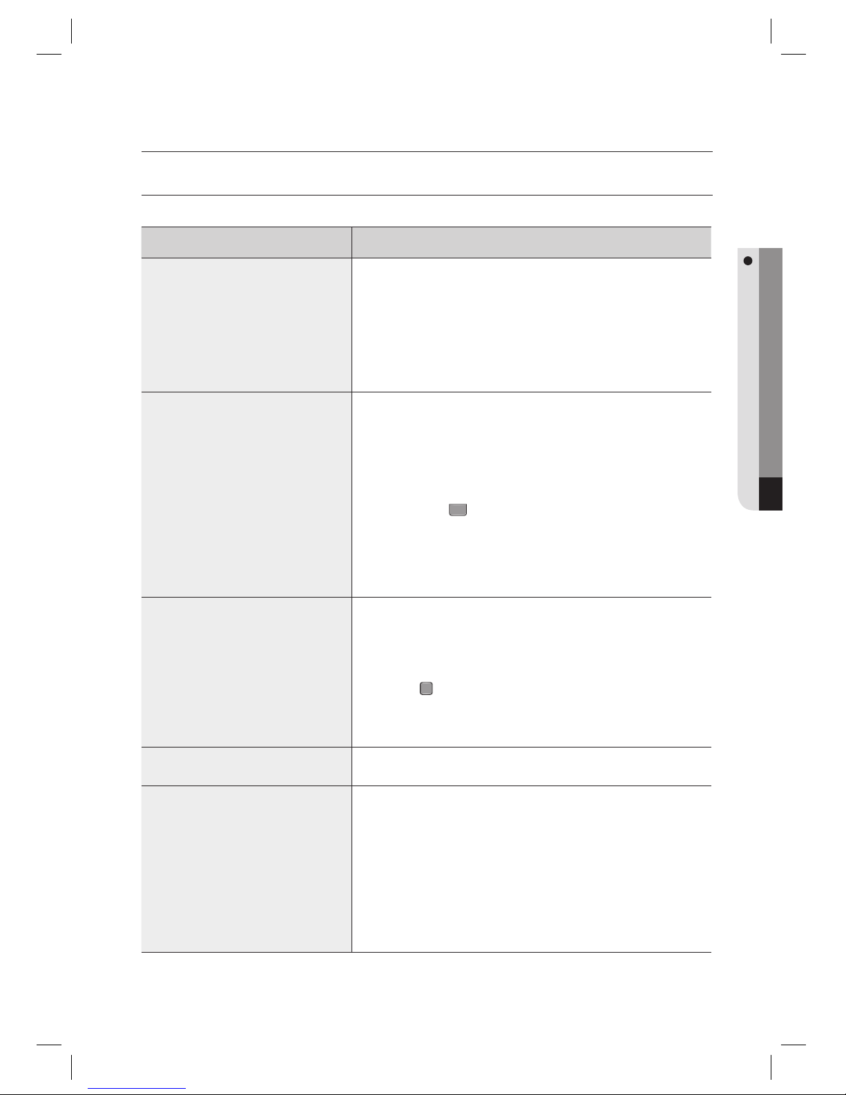
English English _ 77
TROUBLE SHOOTING
troubleshooting
TROUBLESHOOTING
If the product does not function properly, please see the below for trouble shooting.
PROBLEM SOLUTION
A valid card that had been in use became
unregistered after batch-downloading IDs
from a PC.
1) The card ID might be registered only to the controller and not to the PC. During
the process of batch-downloading IDs from the PC, the PC fi rst erases the ID
memory in the unit and rewrites from the beginning. This trouble can happen if
those IDs were not registered on the PC at the point of batch-downloading.
2)
Check whether the card ID is registered on the PC or not.
3) If not, please register the card ID and try again.
4) If the trouble persists after following the procedures above, contact a designated
service center.
I entered the Master ID “00000000” but I
still cannot enter the Setup Mode
(“0000000000” for SSA-S30X1)
1) Try changing the Master ID using the application software. (The Master ID will be
changed to the value of your choice.)
2) If the product does not function properly, follow the steps below to initialize the
system :
After the installation and connections are completed, press the initialize button
and apply power (+12V DC) to turn on the product.
You will see the “Initialize OK? 0:No 1: Yes” message on the screen.
Press the button
1
if you want to initialize the system.
After all the initialization process is completed, the system will be operating on
the normal mode and the screen will display the SAMSUNG logo, Date and Time
information.
3) If the trouble persists after following the procedures above, contact a designated
service center.
No problem with accessing by card, but
cannot access via a manual PIN input.
1) Check whether a beep sounds when you press a key.
If a beep sounds, the problem may be wrong settings.
Proceed as followings:
-
Enter the Master ID (Default=“00000000”) to get into the Setup mode. (“0000000000” for
SSA-S30X1)
- Press the
F
1
button.
- Select ‘USE’ in the [RD#1 KEY INPUT] on the screen.
2)
When there is no beep sound or the problem persists after the [RD#1 KEY INPUT]
has been set to ‘USE’, contact a designated service center.
The unit suddenly returns to the normal
operating mode.
The unit is originally programmed to go back to the normal operating mode when
no buttons are pressed or no cards are read within 60 seconds in the setup mode.
•
The “SCHEDULE ERROR” message
appears when a RFID card is being read.
1) If the unit used to be properly operating before, it is likely that there has been an
electric shock that damaged the internal memory and data. Please initialize the
unit as instructed in the manual.
2) Check if the ID information has been confi gured correctly.
- Check if the Time Schedule is set to the time of your choice.
-
Check if the values for TA and TB are set correctly to the Time Schedule of your choice
during the ID registration.
3) If this unit is connected to a PC software, use the software that allows easy
settings.
4)
If the trouble persists after following the procedures above, contact a designated service center.
Page 78
78_ troubleshooting
troubleshooting
PROBLEM SOLUTION
The “ACCESS DOOR ERR” message
appears when a RF ID card is being read.
1) If the unit used to operate properly before, it is likely that there has been an electric shock
that damaged the internal memory and data.
Please initialize the unit as instructed in the manual.
2) Check if the ID information has been entered correctly during its registration.
- Check if the value for RD is set correctly during the ID registration.
- If the RD value is set to “1”, the door opens only when READER 1 reads tthe card, and
does not open when READER 2 reads the card. If the card is presented to READER 2, the
“ACCESS DOOR ERROR” message will appear.
- If the RD value is set to “2”, the door opens only when READER 2 reads the card, and
does not open when READER 1 reads tthe card. If the card is presented to READER 1,
the “ACCESS DOOR ERROR” message will appear.
- If the RD value is set to either “0” or “3”, the door opens when either READER 1 or 2
reads the card.
3)
If the trouble persists after following the procedures above, contact a designated service center.
The buzzer keeps beeping.
1) Check the door status. If the Door Contact sensor is connected and the Door Open
Timeout Alarm is selected, an alarm is given.
2) Check the Door Contact sensor type: it must be NO/NC-type.
3) Check the setup value for BZ in [10. OUTPUT T/S] under the [F5] menu.
This problem can occur if the time schedule code is set to value between 01 and 10 and
the present time is within the time zone of the selected schedule.
If the wrong time schedule is selected, change it to “00” (this can be set by PC software).
4) Check the Tamper switch of the unit.
5)
If the trouble persists after following the procedures above, contact a designated service center.
The communication between the
controller and the Host PC fails.
1) Please check the settings of the application software and the controller.
- Check if the COMM ID of the controller is registered on the application software.
- Set the different COMM ID when two or more controllers are installed.
- Check if the communication speed (57600bps is default) is the same as the setting on
the software.
- Make sure that the PC’s COM port is set correctly on the S/W.
2) C
heck the wiring for communication.
RS-232 RS-485 (Single)
Product PC Product
RS-485/232
Converter
PC
RX TX RTX(-) RTX(-)
The RS-232 cable
from the converter
TX RX RTX(+) RTX(+)
GND GND
RS-485(Multi Drop)
Product Product
RS-485/232
Converter
PC
RTX(-) RTX(-) RTX(-)
The RS-232 cable from
the Converter
RTX(+) RTX(+) RTX(+)
3) It is recommended to use termination resistors of 120 Ohm between the RTX (+) and RTX
(-) wires when you are using the RS-485 communication. Apply the RS-485 converter to
the same resistors.
Consult a service center or an electric technician if you are not sure how to do it.
4) When a multi-drop communication doesn’t work, test the communication one by one in
order from the fi rst one.
5)
If the trouble persists after following the procedures above, contact a designated service center.
Page 79
English English _ 79
product specifi cations
PRODUCT SPECIFICATIONS
Item SSA-S3010 SSA-S3020 SSA-S3040 SSA-S3011 SSA-S3021 SSA-S3041
User
Total Users
10,000 / 20,000 Users (Selectable)
Fingerprint Users
1,000 2,000 4,000 1,000 2,000 4,000
Fingerprint Templates Size
800 Bytes for 2 fi ngerprint Templates
Event Buffer
20,000 / 10,000 Event Buffers (Selectable)
Power / Current
DC 12V 540mA DC 12V 560mA
Reader Port
1ea: 26bit Wiegand, 8bit Burst for PIN for Anti-Pass-Back 1ea: 34bit Wiegand, 8bit Burst for PIN for Anti-Pass-Back
Reading Time (Card)
30ms
Verifi cation Time
Less than 1sec.
Identifi cation Time
Less than 2sec.
Door Open Time
00~99 Sec. (Default 3Sec.)
Communication
RS-232 / RS-485(Max 32CH), TCP/IP
Baud Rate(bps)
9,600/ 19,200 / 38,400 / 57,600(selectable)
Input Port
4ea : Exit Button, Door Sensor, Aux#1, Aux#2
Output Port
2ea : 2 FORM-C Relay Output (COM, NO, NC) / DC12V~18V Rating Max.2A
2ea : TTL Output / DC5V, Rating MAX.20mA
1ea: 26bit Wiegand Output Supported by TTL Output 1ea : 34bit Wiegand Output Supported by TTL Output
LED Indicator
3 LED Indicators (Red, Green and Yellow)
Beeper
Piezo Buzzer
LCD
Graphic LCD (128 x 64 dots), 72.5mm x 39.5mm (2.85” x 1.56”) View area
Keypad
24 key Numeric Keypad with Back Lighting (12 Function Key included)
LCD Display (Language)
English, Italiano, Français(Selectable) (Optional : Español, Deutsch)
Voice Output (Language)
English (Default) (Optional : Italiano, Français, Español, Deutsch)
Operating Temperature
0°C to +50°C
Operating Humidity
10% to 90% relative humidity non-condensing
Color / Material
Silver with Black / Polycarbonate
Dimension (W x H x D)
191.5 x 159.5 x 44.0
(mm)
Weight
760g
Correct disposal of batteries in this product
(Applicable in the European Union and other European countries with separate battery return systems.)
This marking on the battery, manual or packaging indicates that the batteries in this product should not be disposed of
with other household waste at the end of their working life. Where marked, the chemical symbols Hg, Cd or Pb indicate
that the battery contains mercury, cadmium or lead above the reference levels in EC Directive 2006/66. If batteries are not
properly disposed of, these substances can cause harm to human health or the environment.
To protect natural resources and to promote material reuse, please separate batteries from other types of waste and recycle
them through your local, free battery return system.
Correct Disposal of This Product (Waste Electrical & Electronic Equipment)
(Applicable in the European Union and other European countries with separate collection systems)
This marking on the product, accessories or literature indicates that the product and its electronic accessories (e.g.
charger, headset, USB cable) should not be disposed of with other household waste at the end of their working life. To
prevent possible harm to the environment or human health from uncontrolled waste disposal, please separate these items
from other types of waste and recycle them responsibly to promote the sustainable reuse of material resources.
Household users should contact either the retailer where they purchased this product, or their local government office, for
details of where and how they can take these items for environmentally safe recycling.
Business users should contact their supplier and check the terms and conditions of the purchase contract.
This product and its electronic accessories should not be mixed with other commercial wastes for disposal.
Page 80

P/No. : Z8100239101A
www.samsungsecurity.com
www.samsungtechwin.com
SAMSUNG TECHWIN CO., LTD.
Samsungtechwin R&D Center, 701, Sampyeong-dong, Bundang-gu, Seongnam-si, Gyeonggi-do, Korea, 463-400
TEL : +82-70-7147-8740~60 FAX : +82-31-8018-3745
SAMSUNG TECHWIN EUROPE LTD.
Samsung House, 1000 Hillswood Drive, Hillswood Business
Park Chertsey, Surrey, UNITED KINGDOM KT16 OPS
TEL : +44-1932-45-5300 FAX : +44-1932-45-5325
SAMSUNG TECHWIN AMERICA Inc.
1480 Charles Willard St, Carson, CA 90746, UNITED STATES
Tol Free : +1-877-213-1222 FAX : +1-310-632-2195
www.samsungcctvusa.com
SALES NETWORK
 Loading...