

Page 1

SAMS Pro
SAMS Pro Lite
User Manual
SSA-M2000
SSA-M2100
Page 2

Copyright
©2010 Samsung Techwin Co., Ltd. All rights reserved.
Trad emark
is the registered logo of Samsung Techwin Co., Ltd.
The name of this product is the registered trademark of Samsung Techwin Co., Ltd.
Other trademarks mentioned in this manual are the registered trademark of their respective company.
Restriction
Samsung Techwin Co., Ltd shall reserve the copyright of this document. Under no circumstances, this document
shall be reproduced, distributed or changed, partially or wholly, without formal authorization of Samsung Techwin.
Disclaimer
Samsung Techwin makes the best to verify the integrity and correctness of the contents in this document, but
no formal guarantee shall be provided. Use of this document and the subsequent results shall be entirely on the
user’s own responsibility. Samsung Techwin reserves the right to change the contents of this document without
prior notice.
Warranty
If the product does not operate properly in normal conditions, please let us know. Samsung Techwin will resolve
the problem for free of charge. The warranty period is 3 years. However, the followings are excluded:
Data loss due to a damaged hard disk
If the system behaves abnormally because you run a program irrelevant to the system operation.
Data loss due to virus infection
Deteriorated performance or natural worn-out in process of time
Sensory phenomenon that does not affect the performance or quality of the product
•
•
•
•
•
SAMS Pro / SAMS Pro Lite
User Manual
Page 3

English Englis_ English _3
CONTENTS
INTRODUCTION ON SAMS PRO
9
9 Understanding SAMS Pro
10 SAMS Pro Confi gurations
11 Features
13 System Requirements
13 Installation Procedures
INSTALLATION
14
14 Directory structure of the installation CD
14 Installation of MICROSOFT SQL SERVER
2005 EXPRESS EDITION
23 Installation of MICROSOFT SQL SERVER
MANAGEMENT STUDIO EXPRESS
26 Confi guring MICROSOFT SQL SERVER
2005 EXPRESS EDITION
28 Installing SAMS Pro
33 Installing Key-lock (USB dongle)
35 Installing SSA-X500 Fingerprint Scanner
Driver
CONFIGURATIONS
38
38 Confi guring SAMS Pro Database
Connection
39 Confi guring SAMS Communication Server
Pro Database Connection
LOGGING IN & INITIAL SETUP
42
42 Logging In SAMS Pro
42 Language Setup
43 Building-Floor Setting
44 Site Setting
45 Loop Setting (Serial Communication)
47 Loop Setting (Network Communication)
49 Device Setting
50 Door Setting
51 Company Setting
52 Department Setting
52 Company-Department Setting
53 Access Group Setting
54 Card Holder Management
SCREEN COMPOSITION
56
56 Icons and Descriptions
57 Main Screen
contents
Page 4

4_ contents
contents
SYSTEM MANAGEMENT
58
58 Device Setting Wizard
62 Building-Floor Setting [Add]
62 Building-Floor Setting [Edit]
63 Building-Floor Setting [Delete]
64 Building-Floor Setting [Search]
65 Site Setting [Add]
66 Site Setting [Edit]
66 Site Setting [Delete]
67 Site Setting [Search]
68 Loop Setting [Add – Serial Communication]
70 Loop Setting [Add – Network
Communication]
72 Loop Setting [Edit]
72 Loop Setting [Delete]
73 Loop Setting [Search]
74 Device Setting [Add]
79 Device Setting [Edit]
80 Device Setting [Delete]
80 Device Setting [Search]
81 Door Setting [Add]
83 Door Setting [Edit]
84 Door Setting [Search]
85 Reader Point Setting [Edit]
86 Reader Point Setting [Search]
87 Input Point Setting [Edit]
88 Input Point Setting [Search]
89 Output Point Setting [Edit]
91 Output Point Setting [Search]
92 User Accounts Setting [Add]
93 User Accounts Setting [Edit]
93 User Accounts Setting [Delete]
94 User Accounts Setting [Search]
95 User Accounts Group Setting [Add]
96 User Accounts Group Setting [Edit]
96 User Accounts Group Setting [Delete]
97 User Accounts Group Setting [Search]
98 User Accounts Role Setting [Add]
DEVICE MANAGEMENT
99
99 Initialize Device
100 Device Time Setting
101 Batch Transmit by Device
102 Card Holder Batch Transmit by Device
104 Device Version and Registered No. of User
104 Master Card Management [Add]
107 Master Card Management [Edit]
108 Master Card Management [Delete]
109 Master Card Management [Search]
Page 5

English Englis_ English _5
CONTENTS
ACCESS CONTROL
134
134 Holiday Setting [Add]
135 Holiday Setting [Edit]
135 Holiday Setting [Delete]
136 Holiday Setting [Search]
137 Time Interval Setting [Add]
137 Time Interval Setting [Edit]
138 Time Interval Setting [Delete]
139 Time Interval Setting [Search]
140 Time Schedule [Add]
141 Time Schedule Setting [Edit]
141 Time Schedule Setting [Delete]
142 Time Schedule Setting [Search]
143 Access Group Setting [Add]
144 Access Group Setting [Edit]
145 Access Group Setting [Delete]
146 Access Group Setting [Search]
147 Card Holder Management [Add]
152 Card Holder Setting [Edit]
153 Card Holder Setting [Delete]
154 Card Holder Setting [Search]
OPERATION MANAGEMENT
110
110 Company Setting [Add]
111 Company Setting [Edit]
111 Company Setting [Delete]
112 Company Setting [Search]
113 Department Setting [Add]
113 Department Setting [Edit]
114 Department Setting [Delete]
114 Department Setting [Search]
115 Job Title Setting [Add]
116 Title Setting [Edit]
116 Title Setting [Delete]
117 Title Setting [Search]
118 Position Setting [Add]
118 Position Setting [Edit]
119 Position Setting [Delete]
119 Position Setting [Search]
120 Company-Department Setting
121 Company-Title Setting
122 Company-Position Setting
123 Access Type Setting [Add]
123 Access Type Setting [Edit]
124 Access Type Setting [Delete]
124 Access Type Setting [Search]
125 Fire Group Setting [Add]
127 Fire Group Setting [Edit]
127 Fire Group Setting [Delete]
128 Fire Group Setting [Search]
129 Graphic Map Setting [Add]
131 Graph Map Setting [Edit]
132 Graph Map Setting [Delete]
133 Graph Map Setting [Search]
Page 6

6_ contents
contents
ATTENDANCE
155
155 Closing Hour [Save]
155 Work Code Setting [Save]
156 Overtime Setting [Add]
159 Overtime Setting [Edit]
159 Overtime Setting [Delete]
160 Overtime Setting [Search]
160 Work Time Code Setting [Add]
161 Work Time Code Setting [Edit]
161 Work Time Code Setting [Delete]
162 Work Time Code Setting [Search]
162 Work Schedule Setting [Add]
163 Work Schedule Setting [Edit]
164 Work Schedule Setting [Delete]
164 Work Schedule Setting [Search]
165 Closing Rule Setting [Add]
166 Closing Rule Setting [Edit]
166 Closing Rule Setting [Delete]
167 Closing Rule Setting [Search]
167 Holiday Setting(Attendance) [Add]
168 Holiday Setting(Attendance) [Edit]
169 Holiday Setting(Attendance) [Delete]
169 Holiday Setting(Attendance) [Search]
170 Reader Setting(Attendance) [Add]
171 Reader Setting(Attendance) [Edit]
171 Daily Closing
172 Monthly Closing
174 Revise Daily Closing
175 Closing Report
VIDEO MONITORING
176
176 DVR Settings [Register]
178 DVR Settings [Change]
179 DVR Settings [Delete]
180 DVR Settings [Search]
181 Camera Settings [Register]
183 Camera Settings [Change]
184 Camera Settings [Search]
185 Camera Mapping [Save]
186 Search Camera Mapping [Search]
187 Search Video Data [Search & Play]
188 DVR and Camera Settings Report
189 Live Video
190 Live Video Confi guration
191 Event Video Screen
191 Event Search Screen
MONITORING
192
192 Output Monitoring
194 Integrated Monitoring
Page 7

English Englis_ English _7
CONTENTS
REPORT
211
211 Device Setting Report
212 Holiday Setting Report
213 Time Schedule Report
215 Access Group Setting Report
216 Card holder Report
217 Allowed Card Holders by Doors
218 Accessible Door Report by Person
219 Normal Event Report
221 Alarm Report
222 Auditing Log Report
224 Notifi cation Report
225 Login/Out Report
TOOL
195
195 Language Converter [Save]
196 Language Setting [Save]
196 E-mail/SMS Server Setting [Save]
198 Recipient Setting [Add]
199 Recipient Setting [Edit]
200 Recipient Setting [Delete]
200 Database Backup and Restore
202 Database Backup and Restore (Auto
Management for Event Data)
203 Data Import/Export
205 Option
209 Icon Setting [Save]
210 Icon Setting [Delete]
TROUBLESHOOTING
227
227 Troubleshooting
Page 8

8_ before reading this manual
Please check below items for understanding and proper use of SAMS Pro.
Purpose
This manual provides required information on using SAMS Pro application program. It explains installation and
confi guration of SAMS Communication Server Pro and Microsoft SQL Server 2005, which are required for SAMS
Pro.
Target Audience
This manual is designed for administrators manages the SAMS Pro with its installation, confi guration and
maintenance. The SAMS Pro administrator requires intermediate or higher knowledge and experience on Windows
operating systems and its use. Also, Basic or intermediate knowledge on Microsoft SQL Server 2005 and network
systems is required.
Gloassary
Term Descriptions
SAMS Pro
Means SAMSUNG Access Management System Pro, which is the management
application program for access control.
SAMS Pro Lite
SAMS Pro Lite is an access control management program that is the lite version of
SAMS Pro However, it does not provide the device setup menu and can not be
used independently of SAMS Pro. SAMS Pro Lite is a kind of client program for
SAMS Pro.
SAMS Communication
Server Pro.
Means SAMSUNG Access Management System Communication Server Pro,
which is the dedicated communication server for communicating with ACU
(Access Control Unit).
ACU
Acronym of Access Control Unit, which means a hardware for the access control
system.
Device
Means all hardware units for the access control system. For example, access
controller, biometrics readers etc.
Biometrics Device &
Reader
Access control systems using biometrics information such as fi ngerprint, face
recognition, palmprint, and vein recognition.
Reader
Card recognition device for the access control system. It reads card and sends the
information to the access controller to defi ne the door actions.
Input
Signals accepted by the access controller from access control devices. Such input
can be signals from Exit button, door contact and motion detection sensor.
Output
Signals generated by the access controller and sent to access control devices. Such
output can be connected to door locks, sirens, and buzzers.
Door Lock
Electric door locking system which locks or unlocks a door according to the access
controller’s output signal.
Exit Button
A button to unlock and open a door, which is usually installed inside of a door. When
it is pressed, the door connected to the button is unlocked. Can be connected to the
input port of an access controller.
Door Contact
A device to check if a door is open or closed, usually installed with door lock devices.
Can be connected to the input port of an access controller.
❖
❖
❖
before reading this manual
Page 9
English Englis_ English _9
INTRODUCTION ON SAMS PRO
introduction on SAMS Pro
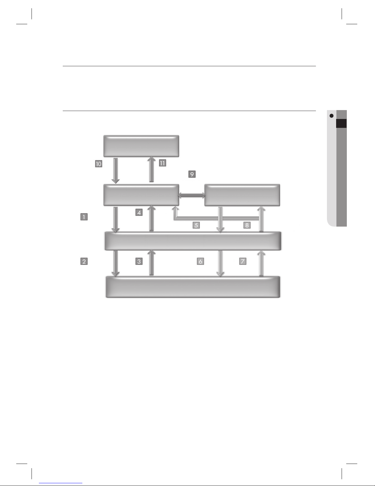
SAMS Pro application program performs data communication to the controller (via serial or TCP/IP) and various
functions based on received data. By integrating devices and application program, it provides higher security through
access controlling where it is required, and also provides additional features with various applications.
UNDERSTANDING SAMS PRO
SAMS Pro supports various devices such as access controllers, fi ngerprint readers, 125KHz/13.56MHz readers and
provides management on such devices as well as integrated monitoring and controlling.
Commands communication of SAMS Pro from/to devices are transferred to the SAMS Communication Server
Pro.
SAMS Communication Server Pro communicates with the controller and processes the command from SAMS
Pro.
SAMS Communication Server Pro receives the command result from the controller.
SAMS Communication Server Pro returns the received data to the SAMS Pro, which will be displayed.
SAMS Communication Server Pro loads communication and controller confi guration information from the
Microsoft SQL Server.
SAMS Communication Server Pro periodically polls for data request to the connected controller.
Receives status events, access status (normal, alarm) events and input events from the controller.
Received information is recorded in the database and transferred to the SAMS Pro for monitoring display.
SAMS PRO searches for or records incoming data in the database.
With the event occurrence time and date set as keys, it searches for videos in the DVR and plays event-related videos.
Displays the live video from the camera connected to a specifi c DVR.
1.
2.
3.
4.
5.
6.
7.
8.
9.
10.
11.
Operating System
& Database
Input/output commands
(Sends ID, time schedule,
etc.)
Communication
Server
Controller
(Hardware)
Transfers commands
from SAMS Pro to the
controller
Returns the transfer result
Receives transfer
result and display
process
Data input/output through user
interface
Normal/Alarm/Input event
database insertion & data transfer
to SAMS Pro
Receives I/O and event data
Requests data in
polling method
Loads communication
properties
Loads controller/setup
properties
SAMS PRO/SAMS PRO LITE
Database Server
(Microsoft SQL Server 2005)
SAMS Communication Server Pro
SSA-P102 / SSA-P102 series
SSA-S3010/S2100 / SSA-R2010 Series
Play DVR-videos in
sync with the event
Display the live screen of a specifi c camera
DVR
Page 10
10_ introduction on SAMS Pro
introduction on SAMS Pro
SAMS PRO CONFIGURATIONS
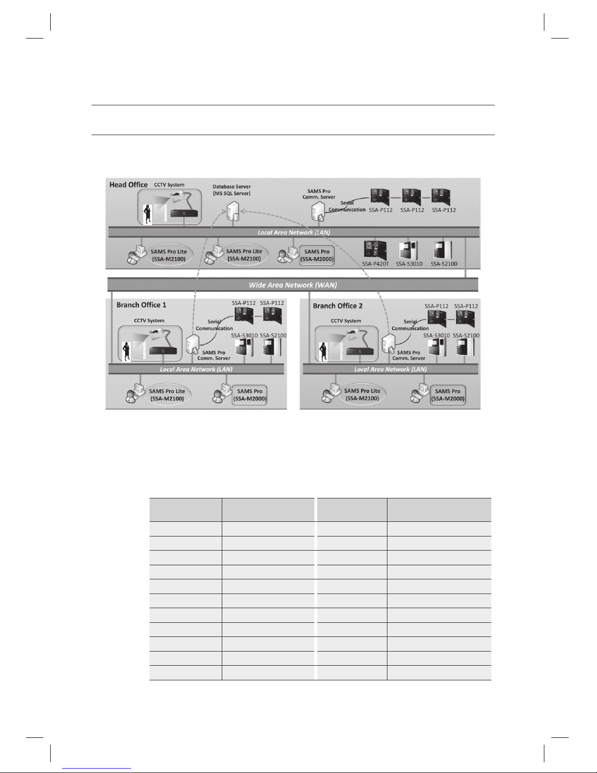
Below is a sample confi guration of SAMS solution which suits to a single building or organization. In this example,
SAMS Pro, SAMS Communication Server Pro and Microsoft SQL 2005 Server are installed on dedicated machines
separately. It is also possible to install and operate all programs on a single computer.
When connecting devices to SAMS Communication Server Pro via serial communication, connecting different
product models to a single serial loop is not supported.
For example, you cannot install SSA-P102, SSA-P400, SSA-S3010 and other products in the same serial loop. To
connect both SSA-P102 and SSA-P400 in serial communication, two separate serial loops are required for each
SSA-P102 and SSA-P400.
The following DVR models are compliant with SAMS Pro.
SAMS Pro Model
Notation
Actual Model Names
SAMS Pro Model
Notation
Actual Model Names
SHR-204X SHR-2040, SHR-2042 SHR-808X SHR-8080, SHR-8082
SHR-208X SHR-2080, SHR-2082 SHR-816X SHR-8160, SHR-8162
SHR-216X SHR-2160, SHR-2162 SRD-47X SRD-470, SRD-470D, SRD-471
SHR-504X SHR-5040, SHR-5042 SRD-83X SRD-830, SRD-830D
SHR-508X SHR-5080, SHR-5082 SRD-161X
SRD-1610, SRD-1610D
SHR-516X SHR-5160, SHR-5162 SRD-163X
SRD-1630, SRD-1630D
SHR-604X SHR-6040, SHR-6042 SRD-85X SRD-850, SRD-850D, SRD-851
SHR-608X SHR-6080, SHR-6082 SRD-165X
SRD-1650, SRD-1650D, SRD-1651
SHR-616X SHR-6160, SHR-6162 SRD-87X SRD-870, SRD-870D, SRD-871
SHR-708X SHR-7080, SHR-7082 SRD-167X
SRD-1670, SRD-1670D, SRD-1671
SHR-716X SHR-7160, SHR-7162
J
Page 11

English Englis_ English _11
INTRODUCTION ON SAMS PRO
FEATURES
SAMS Pro application program performs data communication to the controller (via serial or TCP/IP) and various
functions based on received data. By integrating devices and application program, it provides higher security through
access controlling where it is required, and also provides additional features with various applications.
SAMS Pro consists of 3 program modules. They are access control management console SAMS Pro, dedicated
communication module SAMS Communication Server Pro and Microsoft SQL Server 2005 as the database storage.
SAMS Pro supports the latest UI (User Interface). It also provides plentiful tooltips which enables easier and comfortable
adaptation of the software. Device Setting Wizard and quick view of properties enable users with easier and faster
installation and confi guration of the products.
SAMS Pro provides various functions for access control. It provides door monitoring, access event monitoring and log of
program manipulation history for later reference for possible fabrication. Additionally, it provides simple attendance
monitoring (for regular offi ce works) which enables users with attendance management based on access information.
SAMS PRO has integrated access control system with the DVR via the network, which enables you to play the DVR video
recorded on the same time and date when the ordinary or alarm events occurred in the access control system. Namely, it
synchronizes the text-based access history with the video information to provide an enhanced security system.
Integration of access control with video (DVR) analysis
Supports a large lineup of DVR models manufactured by Samsung Techwin. It also maps access control points for
specifi c areas (entrance, input, reader, etc) with the camera, synchronizing a text-based access history with video
information before being played. Furthermore, you can monitor the live video.
Multi-site Control and Communication Server
Supports controlling multiple sites. When communication servers are installed on each site, you can connect to
multiple sites simultaneously or a single site at a time. You can distribute the load to multiple communication servers
installed in one site if there are lots of controllers, for better performance.
Multilingual Support
Supports multilingual interface based on unicode. You can set to 10 languages other than pre-installed Korean and
English. By using built-in interface converter of SAMS Pro, you can select and convert to the desired language.
Multi-ID Management
Access control accepts various information of users. Photograph and vehicle information can be added for a
user. It supports managing multiple IDs for one user.
Graphic Map
You can set the graphic fl oor plan for corresponding building’s fl oor based on the area and fl oor information. You
can add and position doors, readers, I/O points at your preference. Depending confi gured options, the graphic
map appears on events to visually notify the administrator with current event generations. By placing various
fi gures and images on a map, you can setup an intuitive visual monitoring screen.
Event Notifi cation & Acknowledgement
Administrator who is responsible for managing alerts can confi rm and acknowledge events.
Alarm events are released with alarm indication only when an administrator acknowledges, and can be viewed in reports.
Font Coloring for Events
According to event types, administrator can set different colors to events according to their types. Event coloring
enables better recognition and distinguishing events while monitoring.
Page 12

12_ introduction on SAMS Pro
introduction on SAMS Pro
Various Reports
Various report options are provided to suit administrator’s preference. Monitoring upon event types, coloring,
sound effect as well as font type and event icon can be changed.
Data Exporting & Conversion
It supports data exporting and data conversion. Exporting to a text fi le (.txt) is available. By exporting data, it can be
utilized for other applications such as attendance monitoring, salary management, ERP etc. Conversion of reports
to PDF, TIF image and text fi le is available. This function can be used for sending reports through internet and
emails.
Device Setting Wizard
Setup wizard is provided for easier confi guration on devices. The device setting wizard provides simplifi ed setup
steps for automatic setup, and its automatic search for controllers enables faster and easier setup.
(This is not available in SAMS Pro Lite.)
Comprehensive Tooltips
Plentiful and comprehensive tooltips with detailed information are provided for each input items of interfaces, users
can easily understand its usage.
Integrated Monitoring
The integrated monitoring screen can be re-organized by splitting and merging at user’s preference. Its screen
composition can be customized to user’s optimal convenience, including the information columns of event and
alarm list items. Monitoring screen can be splitted for use with multiple monitors, and can be integrated with access
view, alarm view and graphic map in one screen.
Powerful History Management
Supports logging for program logging in/out, operation history including add, edit, delete actions, data transfers to
devices and transfer results, which enables trouble tracing with reports.
Distributed Processing
In this example, SAMS Pro, SAMS Communication Server Pro and Microsoft SQL 2005 Server can be installed on
dedicated computers (or servers) separately. By doing this, dedicated servers work for its own function and provide
more powerful and reliable operations.
Supports Massive Database
Employs Microsoft SQL Server 2005 for more reliable database support.
Page 13
English Englis_ English _13
INTRODUCTION ON SAMS PRO
SYSTEM REQUIREMENTS
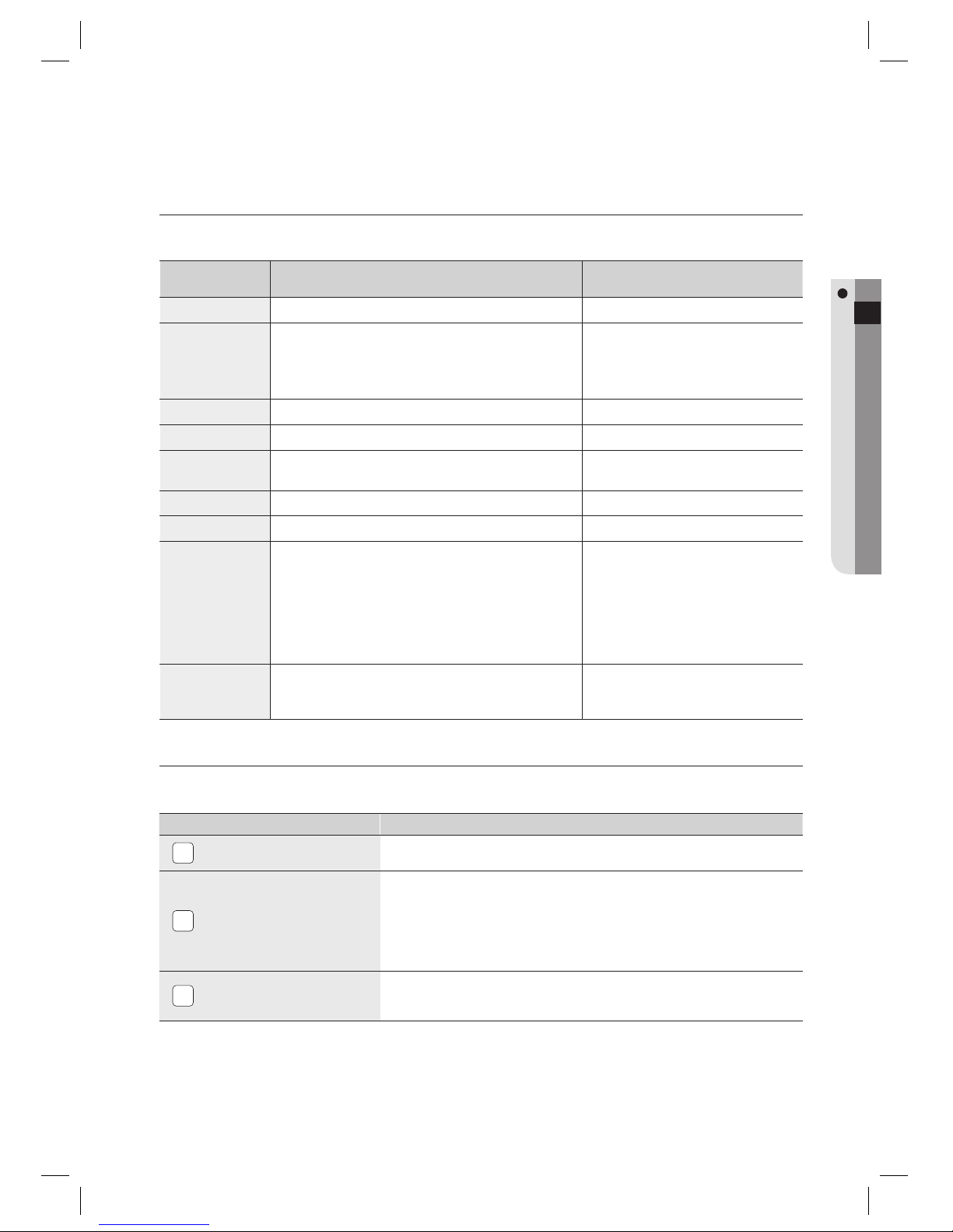
The information below is the suggested minimum requirements of hardware and operating system for SAMS Pro.
Hardware /
Operating System
Requirements
CPU
Intel Core2Duo 2.4GHz or faster
OS
Windows XP
Windows Vista
Windows 2003 Server
The operating system here refers to a 32-bit operating system.
It is recommended to keep the operating
system updated and install the latest
service packs.
DRAM
2GB main memory or more
HDD
50GB free disk space or more
Graphics
32-bit color, 1024x768 or higher resolution, 512 MB
video ram or more
Network
10/100 Ethernet NIC
CD ROM
CD-ROM drive of x8 or faster
Software
Requirements
Microsoft Windows Installer 3.1 or later
Microsoft Internet Explorer 7.0 Service Pack 1
MDAC (Microsoft Data Access Components) 2.8 Service
Pack 1
Microsoft .NET Framework 2.0 or later, Microsoft XML
6.0 or later
DirectX 9.0 or later
Database
Microsoft SQL Server 2005 Express Edition or Microsoft
SQL Server 2005 Standard/Enterprise
It is recommended to keep the database
management system updated and install
the latest service packs.
INSTALLATION PROCEDURES
Please follow the steps below to install the SAMS Pro.
Installation Procedures Descriptions
1
Install the SAMS Pro
application software.
Setup will install SAMS Pro/SAMS Pro Lite program.
2
Install the key-lock driver.
If you are installing a demo version, the key lock driver is not necessary.
In the demo version, the access control will be limited to 2 registered doors and 100
registered users.
If you install a full version, you should install the key lock driver before proceeding.
Connect the blue key lock for SAMS Pro, and the green one for SAMS Pro Lite, to
the USB port.
3
Install the SSA-X500 driver.
Installation is not required in case of you don’t use the fi ngerprint scanner. This
enables with fi ngerprint recognition, fi ngerprint data storing and transfer to the
SAMS Pro application program by using the fi ngerprint scanner.
Page 14

14_ installation
installation
DIRECTORY STRUCTURE OF THE INSTALLATION CD
INSTALLATION OF MICROSOFT SQL SERVER 2005 EXPRESS EDITION
The version of Microsoft SQL Server 2005 Express Edition provided by default is SP3. For the Windows XP
environment, the OS should have been upgraded with SP3. If you install Microsoft SQL Server 2005 Express Edition
SP3 on Windows XP SP2, this can cause system malfunction or blue screen from abnormal operation.
During the installation of Microsoft SQL Server 2005 Express Edition SP3, you are prompted to install MSXM6 if it
has not been installed. Installing MSXML6 on Windows XP SP3 will cause an error during the installation. If you
encounter a problem, refer to the troubleshooting section in this manual.
The following installation process is not applicable to SAMS Pro Lite.
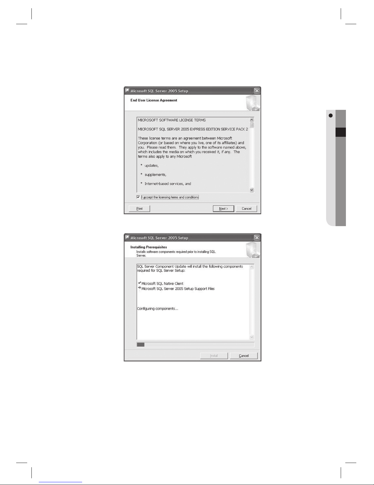
Run the Microsoft SQL Server 2005 Express installer fi le SQLEXPR.EXE from the CD.
Installation path is as below:
J
1.
J
< SAMS Pro > < SAMS Pro Lite >
Page 15
English Englis_ English _15
INSTALLATION
Check [I accept the licensing terms and conditions] to agree the terms and click [Next].
Click [Install] to begin the installation.
2.
3.
Page 16
16_ installation
installation
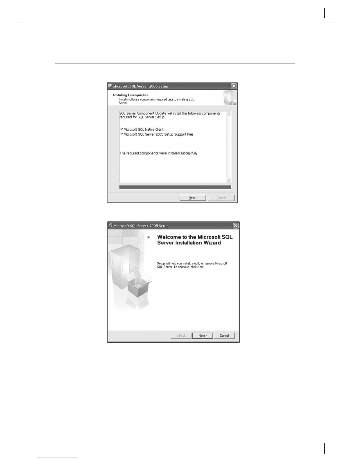
Installation process completes a few minutes after beginning the installation. Click [Next] to proceed.
Upon completion of the initial installation, it begins with SQL server installation. Click [Next] to proceed.
4.
5.
Page 17
English Englis_ English _17
INSTALLATION
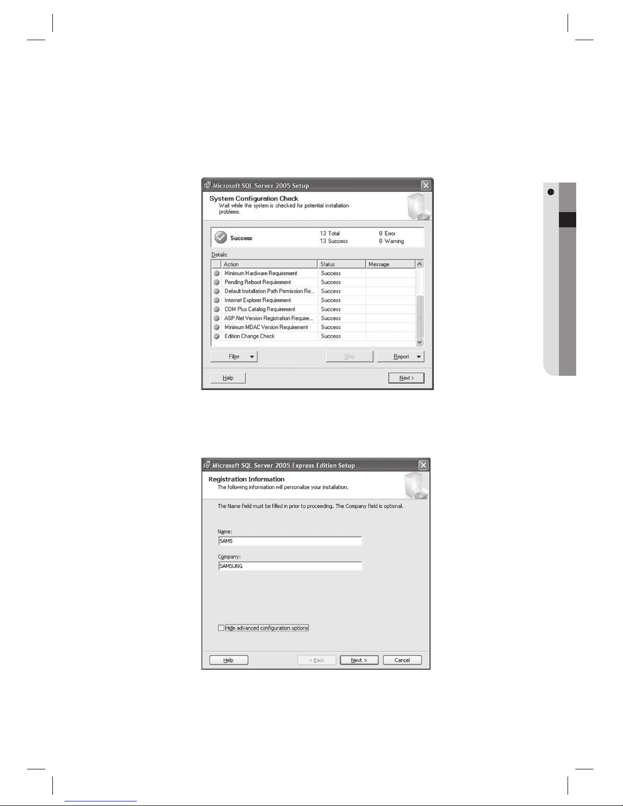
Make sure that system confi guration suffi ces the SQL Server 2005 requirements. When all items listed show
Success in the Status fi eld, you can proceed to install SQL Server 2005. If there exist any item without Success
status, consult your SQL Server administrator or Microsoft customer care for technical assistance. Click [Next]
to proceed.
Provide the Name and Company Name, and uncheck the [Hide advanced confi guration options]. For proper
confi guration of SQL Server 2005 Express Edition, this option must be unchecked to confi gure the advanced
options in later installation steps. Click [Next] to proceed.
6.
7.
Page 18
18_ installation
installation
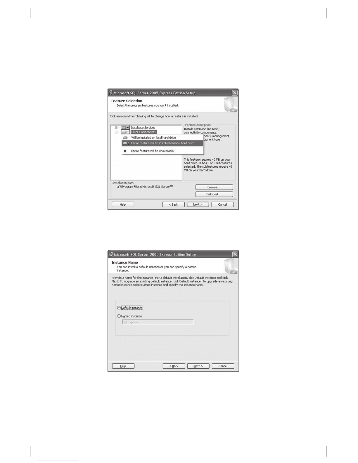
Left click [Database Services] and [Client Components] to show context menu and select [Entire feature will be
installed on local hard drive]. Click [Next] to proceed.
Select the [Default instance]. If you are using the SQL Server that had been installed before, you cannot choose
the Default Instance. In this case, stop new installation of SQL Server and use the previously installed SQL
Server. For a fresh new installation, it is always recommended to use [Default Instance]. Click [Next] to proceed.
8.
9.
Page 19
English Englis_ English _19
INSTALLATION
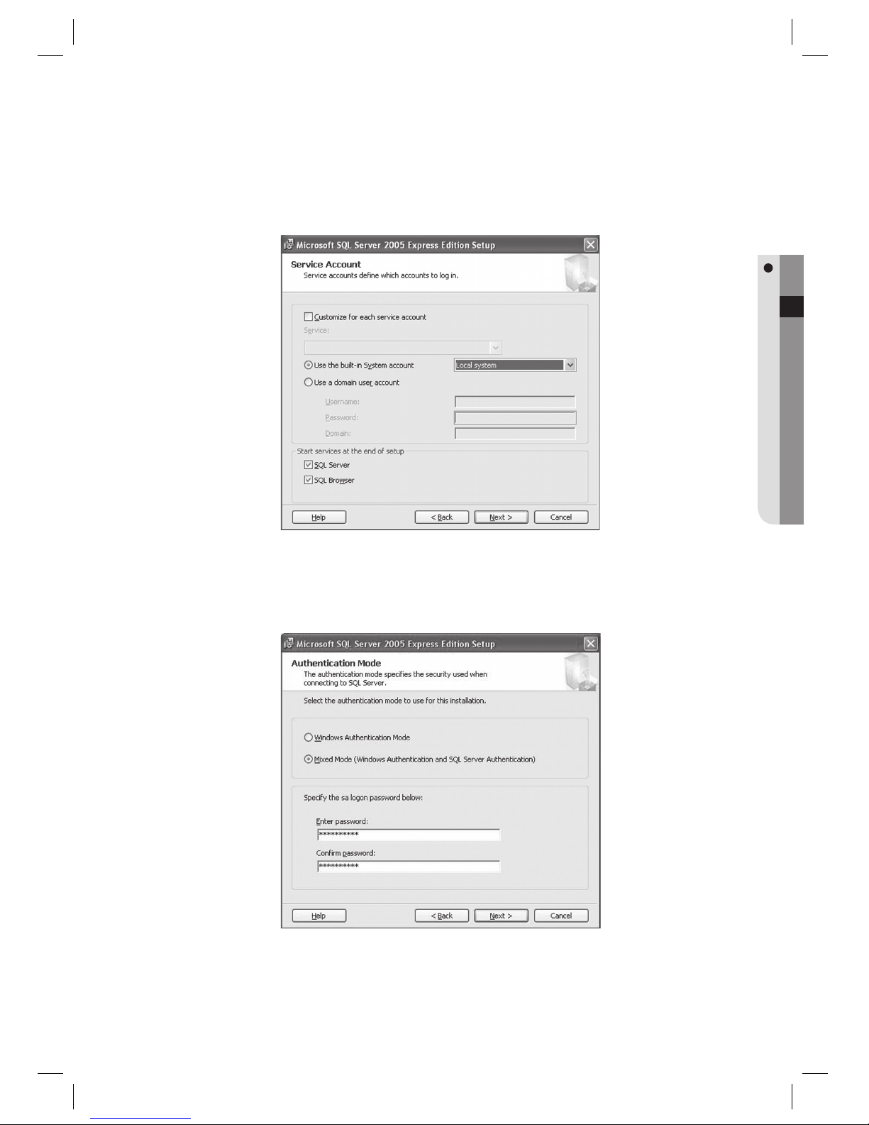
Select the [Use the built-in System account]. If Network service is selected by default, you must change it
to [Local system]. Check both [SQL Server] and [SQL Browser] in the bottom of the screen. Click [Next] to
proceed.
Select the [Mixed Mode]. Enter your password for accessing SQL Server 2005. Don’t forget the password,
memorize it or keep recorded. If you forgot the password, you cannot use the database. Click [Next] to
proceed.
10.
11.
Page 20
20_ installation
installation
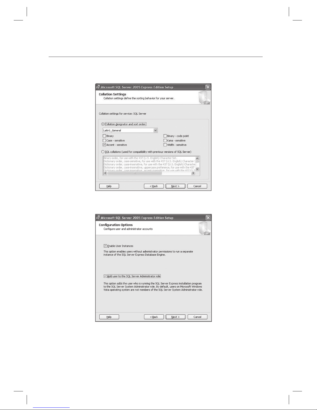
Collation is confi gured automatically according to the language setting of the operating system in use. Use the
default setting or change the language environment at your preference. Click [Next] to proceed.
Select the [Enable User Instances] and [Add user to the SQL Server Administrator role]. Click [Next] to proceed.
12.
13.
Page 21
English Englis_ English _21
INSTALLATION
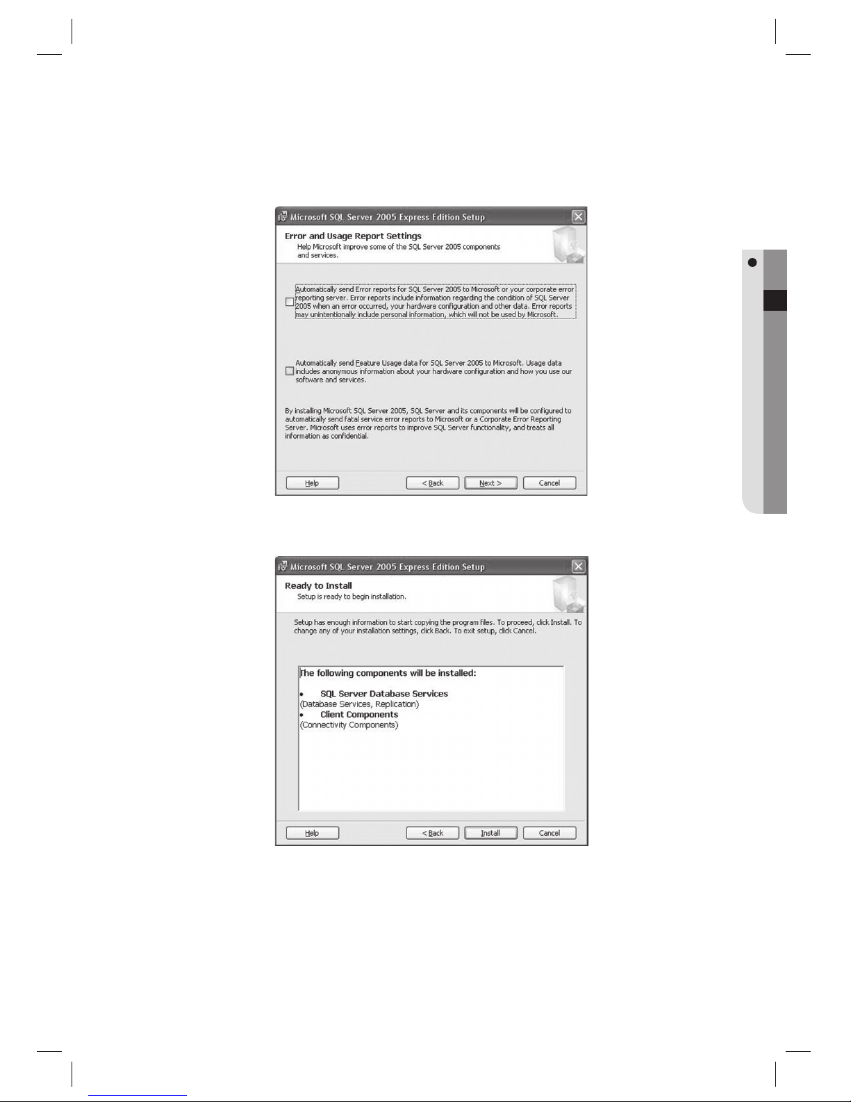
Click [Next] to proceed.
Click [Install] to begin the installation.
14.
15.
Page 22
22_ installation
installation
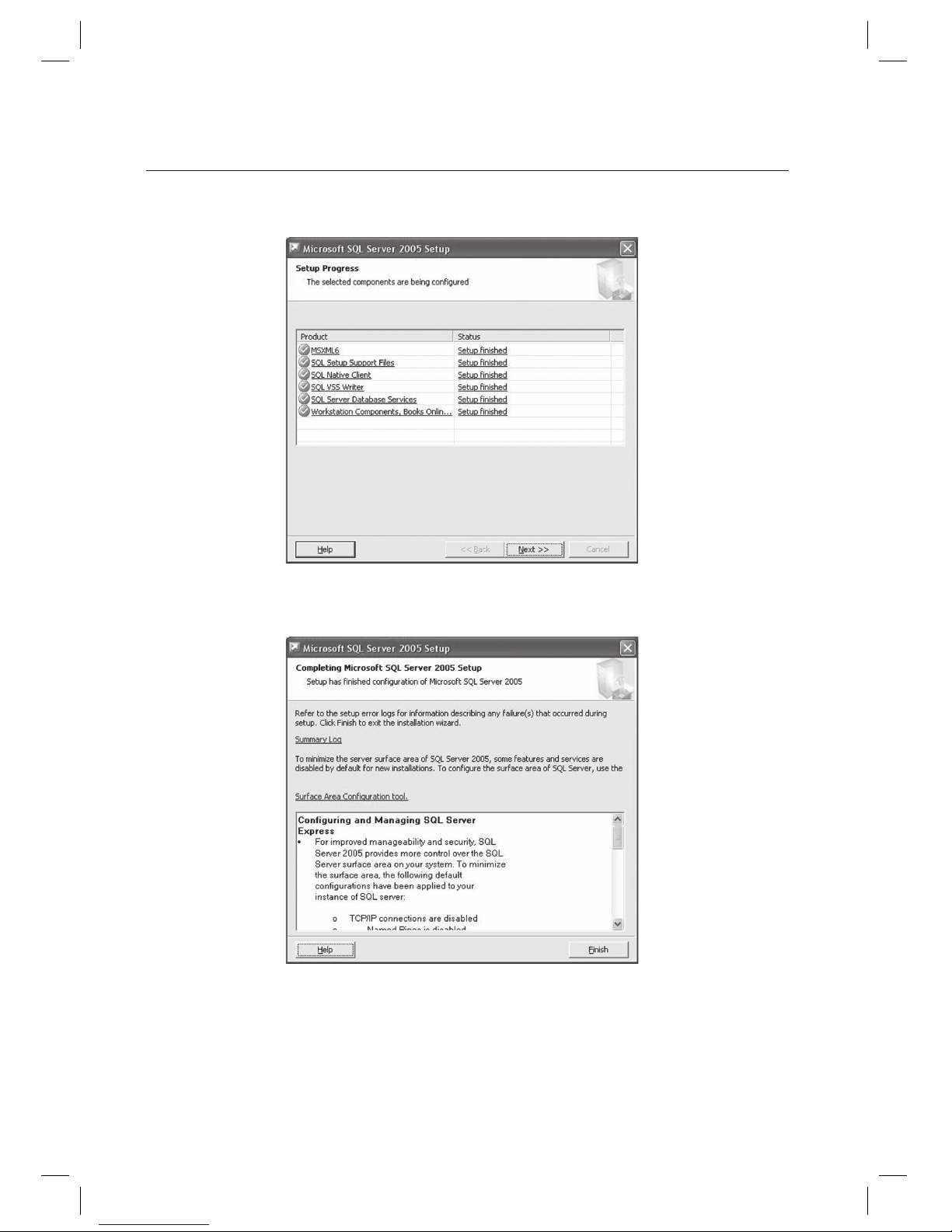
Installation begins and displays completion message for each installation item. Once completed, click [Next] to
proceed.
Click [Finish] to fi nish the installation. Once the installation is completed, restart the computer.
16.
17.
Page 23
English Englis_ English _23
INSTALLATION
INSTALLATION OF MICROSOFT SQL SERVER MANAGEMENT STUDIO EXPRESS
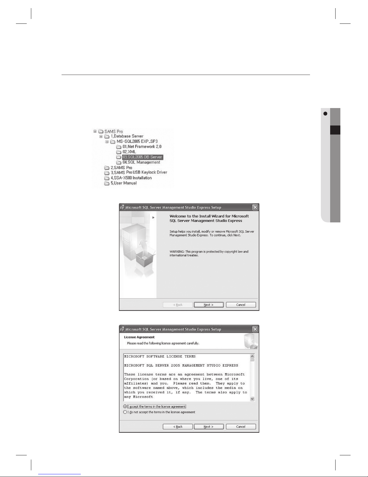
Run the Microsoft SQL Server Management Studio Express installer fi le SQLServer2005_SSMSEE.msi from the
CD.
The following installation process is not applicable to SAMS Pro Lite.
Installation path is as below:
Click [Next] to proceed.
Check [I accept the terms in the license agreement] to agree the terms and click [Next].
1.
J
2.
3.
Page 24
24_ installation
installation
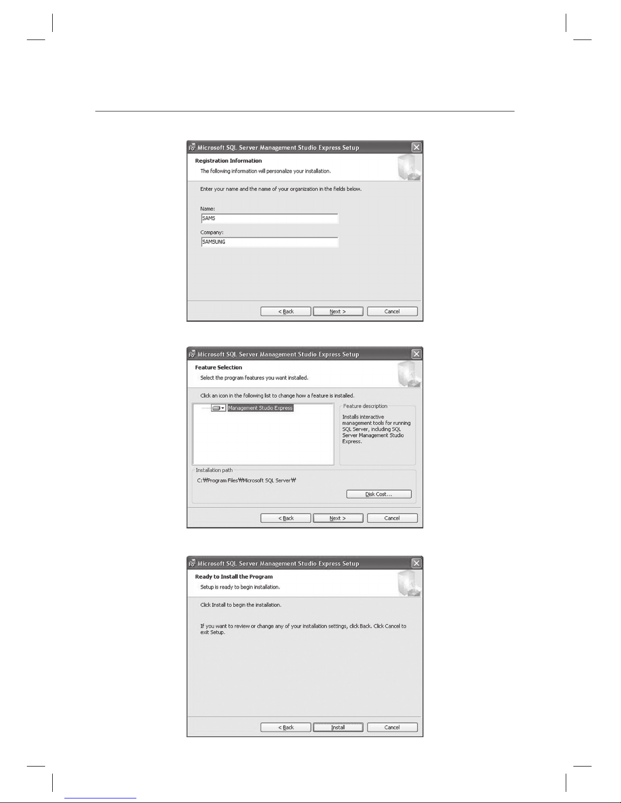
Enter the name and company name, click [Next] to proceed.
Select the desired installation options and click [Next] to proceed.
Click [Install] to begin the installation.
4.
5.
6.
Page 25
English Englis_ English _25
INSTALLATION
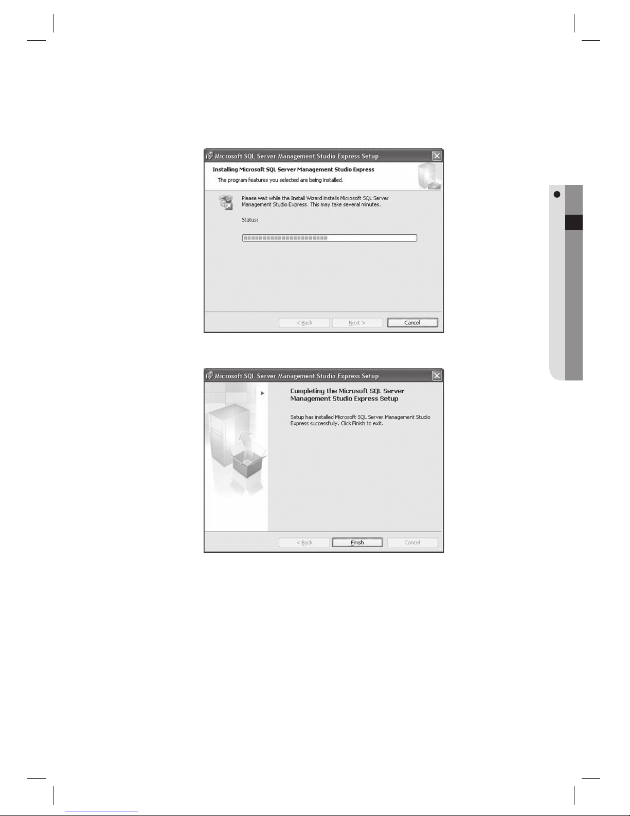
Wait until the installation process completes.
Click [Finish] to fi nish the installation.
7.
8.
Page 26
26_ installation
installation
CONFIGURING MICROSOFT SQL SERVER 2005 EXPRESS EDITION
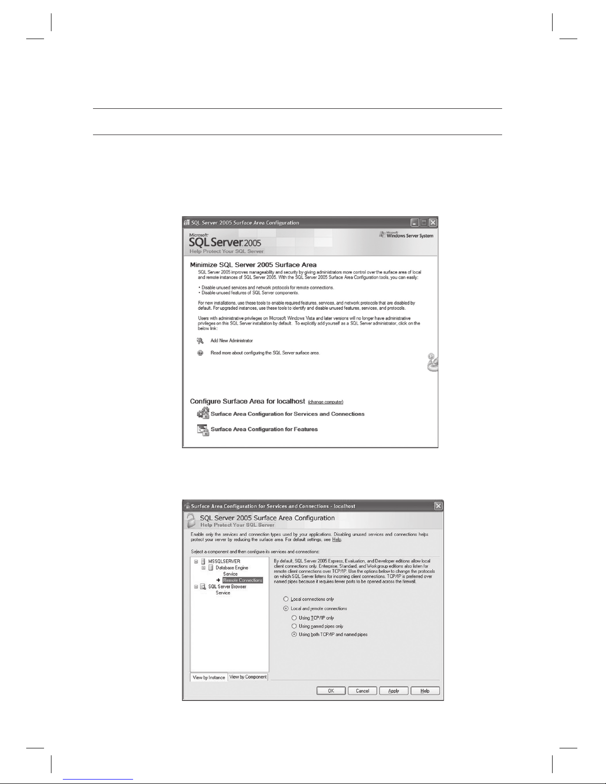
Select [Start] > [All Programs] > [Microsoft SQL Server 2005] > [Confi guration tools] > [SQL Server Surface Area
Confi guration].
Select the [Surface Area Confi guration for Services and Connections].
On the left tree, click [Database Engine] and select the [Remote Connections] from the submenu. On the right
pane, select the [Local and remote connections] and select the [Using both TCP/IP and named pipes].
Click [Apply].
1.
2.
3.
Page 27
English Englis_ English _27
INSTALLATION
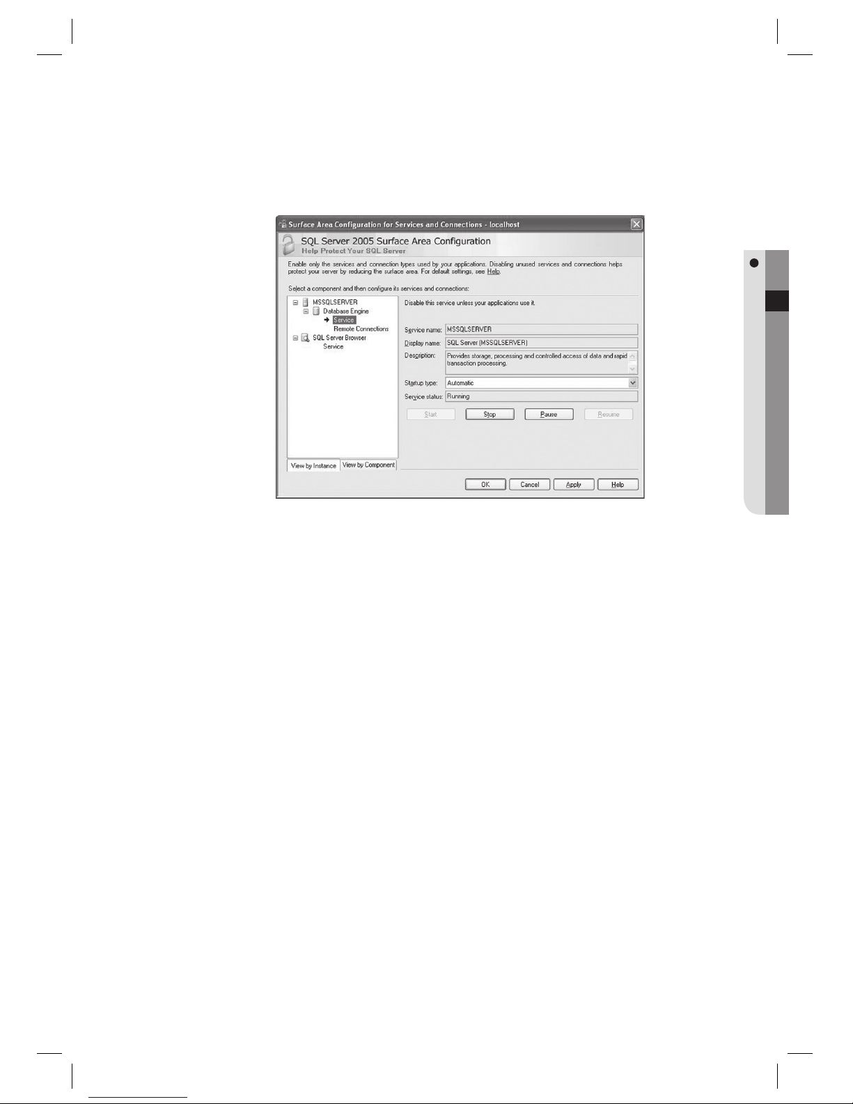
On the left tree, click [Database Engine] and select the [Services] from the submenu. On the right pane, click
[Stop] to temporarily pause the SQL server operation. Once stopped, click [Start] to restart the server.
4.
Page 28
28_ installation
installation
INSTALLING SAMS PRO
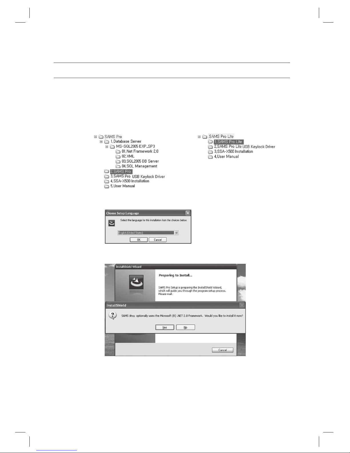
Run the SAMS Pro installer fi le SAMS Pro_vx.xx_yyyymmdd.exe from the installation CD.
For SAMS Pro Lite, run the executable program of SAMS Pro Lite_vx.xx_yyyymmdd.exe.
Installation path is as below:
Select the language for the installation process and click [OK].
SAMS Pro requires the Microsoft .NET Framework 2.0. Click [Yes] to begin the installation.
If the Microsoft .NET Framework 2.0 is already installed on the computer, this step may be skipped.
1.
J
2.
3.
J
< SAMS Pro > < SAMS Pro Lite >
Page 29
English Englis_ English _29
INSTALLATION
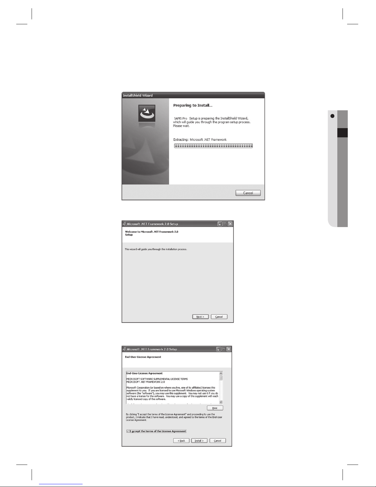
Wait until the installation process begins.
NET Framework 2.0 installation begins. Click [Next] to proceed.
Check [I accept the terms of the License Agreement] and click [Install].
4.
5.
6.
Page 30
30_ installation
installation
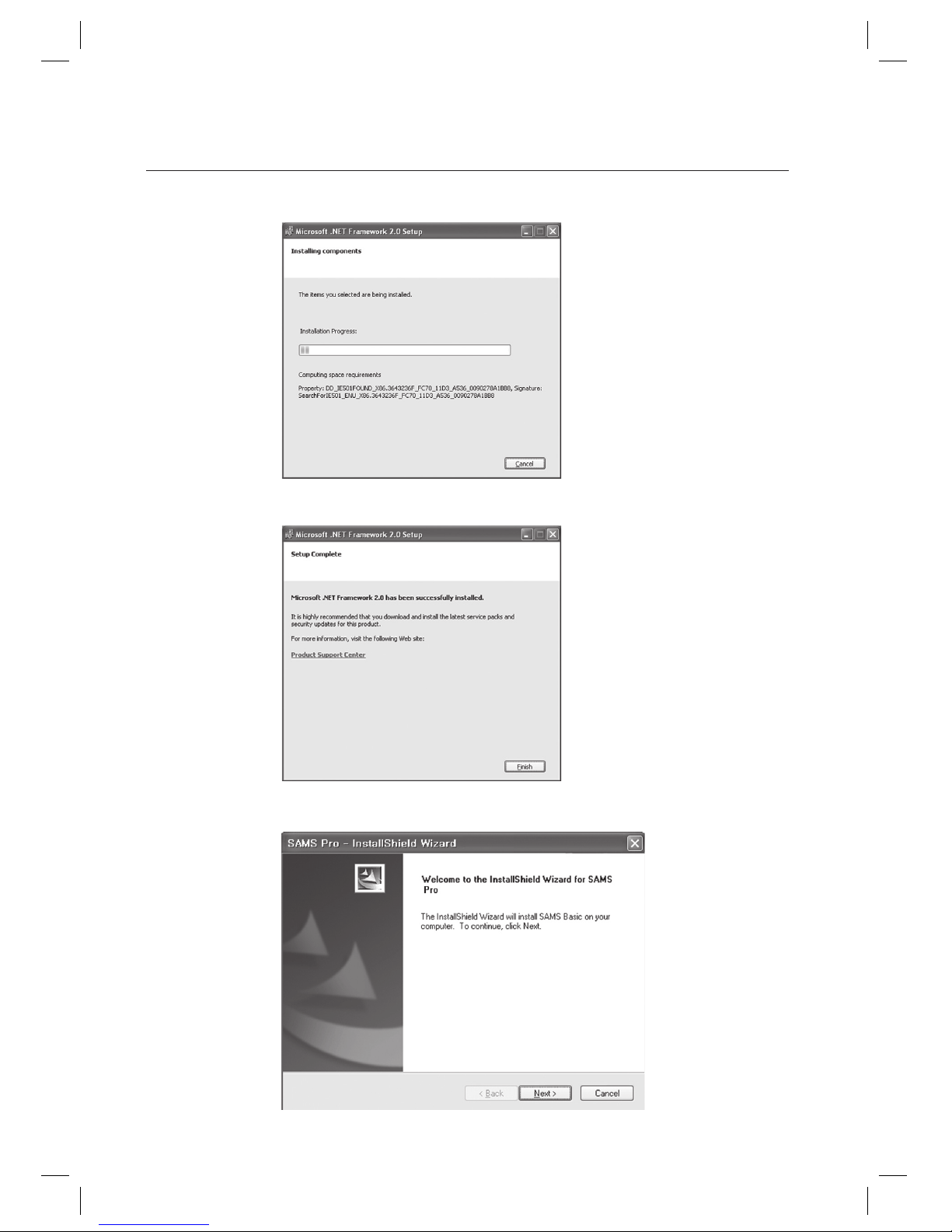
The installation begins. Wait until the installation process completes.
Click [Finish] to fi nish the installation.
SAMS Pro installation wizard appears. Click [Next] to proceed.
7.
8.
9.
Page 31
English Englis_ English _31
INSTALLATION
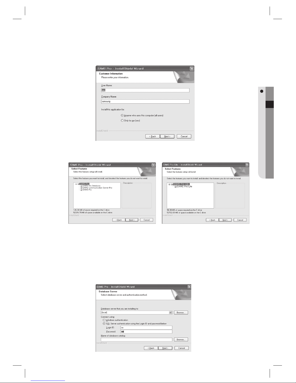
Provide the user information and click [Next].
From 3 features below, select the features that you want to install, and click [Next].
[Database server that you are installing to:] Provide the server address of the computer that has installed
Microsoft SQL Server 2005 Express Edition. If you have followed the onscreen instructions to install Microsoft
SQL Server 2005 Express Edition, it will be installed on the same computer without any instance. If this is the
case, select [(local)]. If you have created an instance (SQLEXPRESS instance) during installation, provide
“(local)\instance name”, or “(local)\SQLEXPRESS”. Check the [SQL Server authentication using the Login ID
and password below] option. [Login ID:]You must enter nothing else but “sa” in the input box.
[Password:]Provide the password that you have specifi ed when installing MICROSOFT SQL SERVER 2005
EXPRESS EDITION. Click [Next].
This step is not applicable to the installation of SAMS Pro Lite.
10.
11.
12.
J
< SAMS Pro > < SAMS Pro Lite >
Page 32
32_ installation
installation
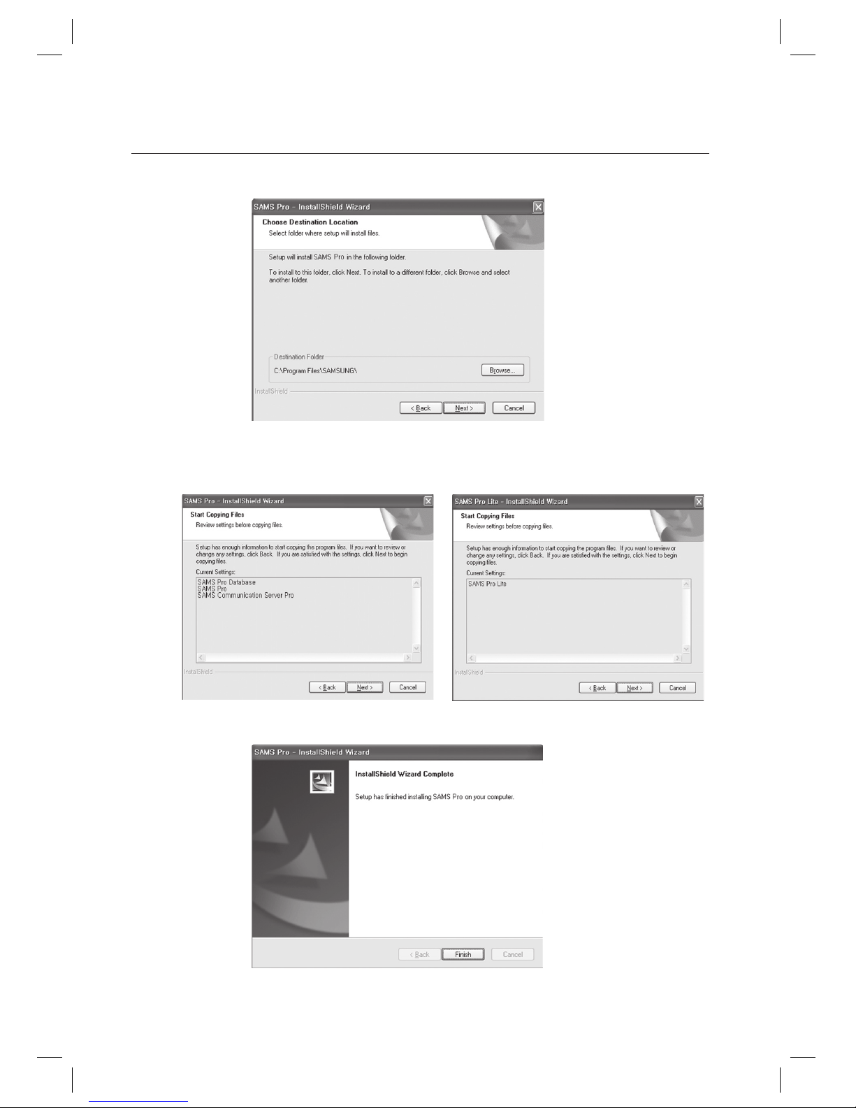
Using [Browse], specify a folder where the program fi les are installed , and click [Next].
Check if all the necessary programs are included, and click [Next].
Click [Finish] to complete the installation.
13.
14.
15.
< SAMS Pro > < SAMS Pro Lite >
Page 33
English Englis_ English _33
INSTALLATION
INSTALLING KEY-LOCK (USB DONGLE)
For regular SAMS Pro as licensed, the USB type key lock and its driver should be installed on the computer. If the USB
key lock is not available, or not plugged in the USB port, the access control of SAMS Pro is limited to 2 registered doors
and 100 registered users.
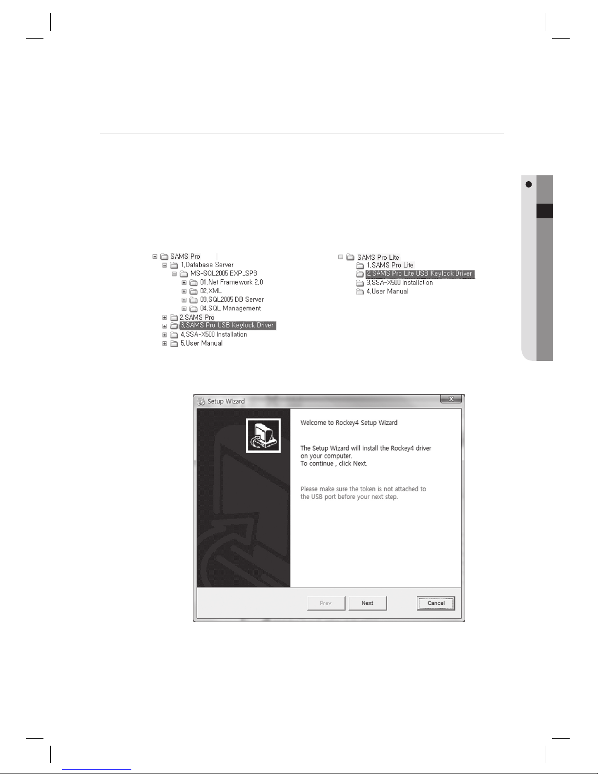
Run the key-lock driver installer fi le InstDrv.exe from the installation CD.
Installation path is as below:
Click [Next] to proceed.
1.
J
2.
< SAMS Pro >
< SAMS Pro Lite >
Page 34
34_ installation
installation
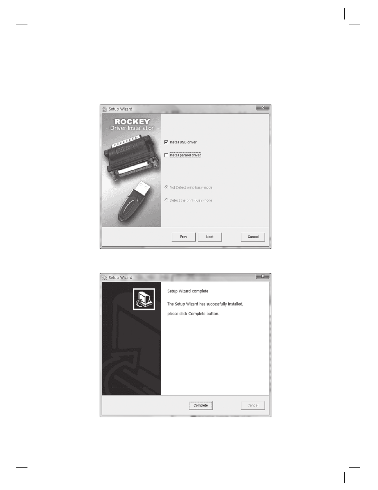
Check [Install USB driver]. Uncheck [Install parallel driver].
Click [Next] to proceed.
In a moment, driver installation completes. Click [Complete].
A message to restart the computer may appear depending on systems. Restart the computer if the restart message
appears.
3.
4.
5.
J
Page 35
English Englis_ English _35
INSTALLATION
INSTALLING SSA-X500 FINGERPRINT SCANNER DRIVER
SSA-X500 fi ngerprint scanner should be connected to a USB port of the computer for fi ngerprint registration. And its
device driver is required to be installed on the computer.
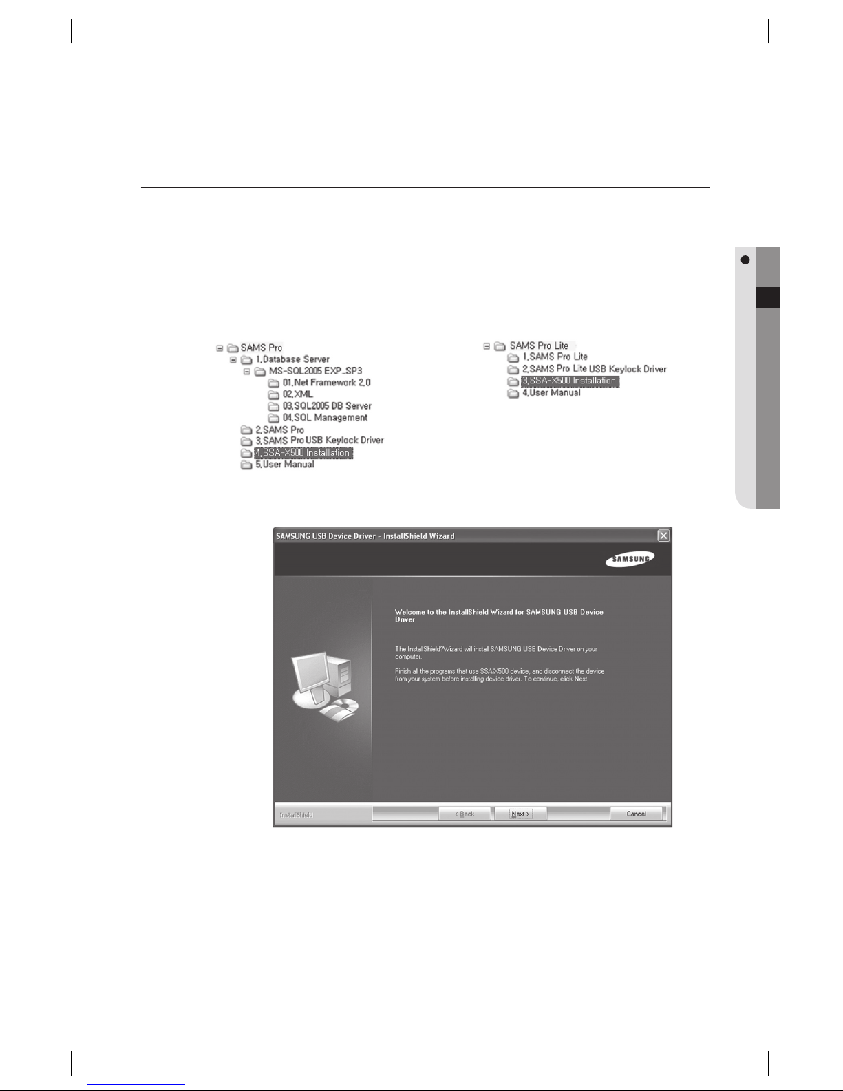
Run the SSA-X500 driver installer fi le Setup.exe from the installation CD.
Installation path is as below:
Click [Next] to proceed.
1.
J
2.
< SAMS Pro >
< SAMS Pro Lite >
Page 36
36_ installation
installation
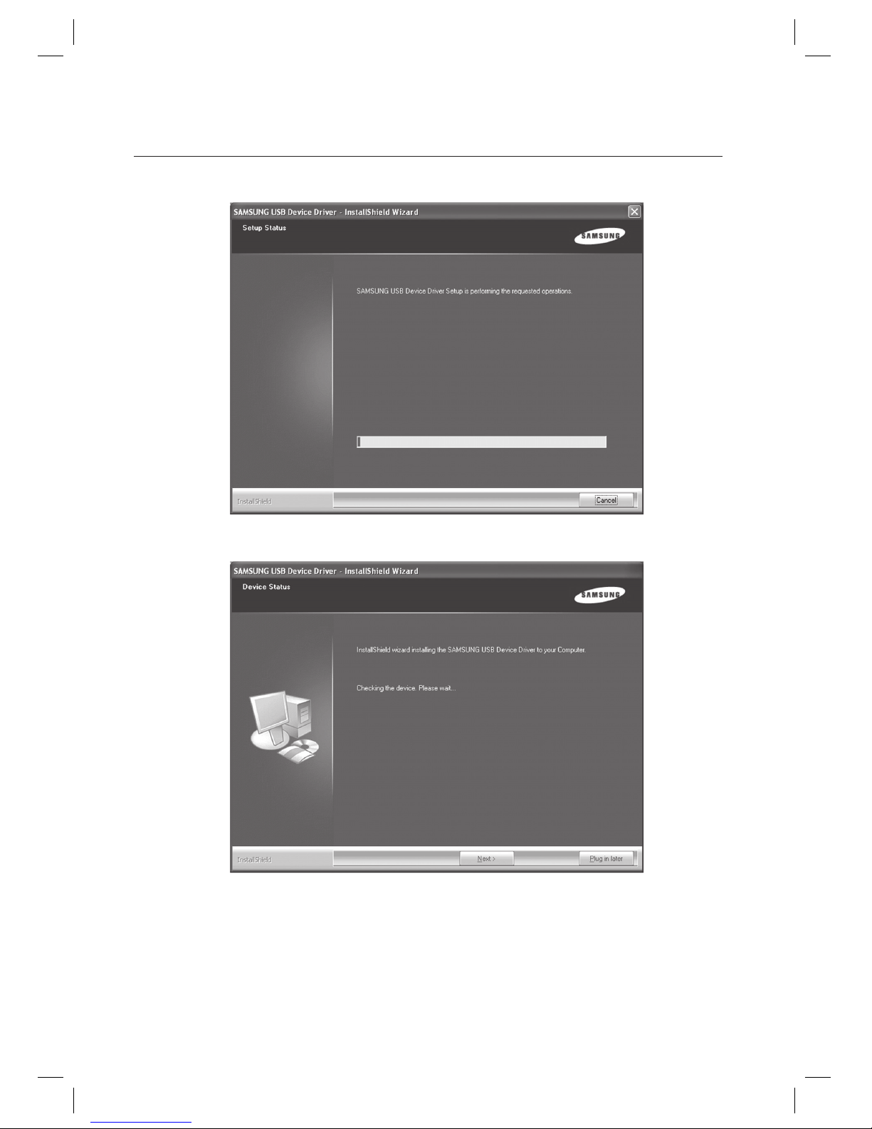
Wait until the installation process completes.
Wait until the device inspection completes.
3.
4.
Page 37
English Englis_ English _37
INSTALLATION
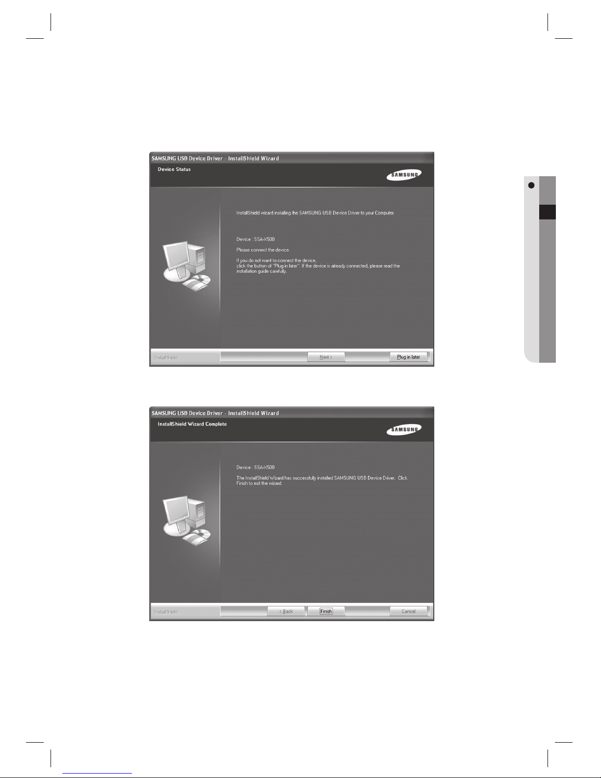
Connect the SSA-X500 to a USB port of the computer.
Click [Next] to proceed.
Click [Finish].
5.
6.
Page 38
38_ confi gurations
CONFIGURING SAMS PRO DATABASE CONNECTION
When the SAMS Pro is installed for the fi rst time, database server connection should be confi gured using the
SAMS Pro Confi g program.
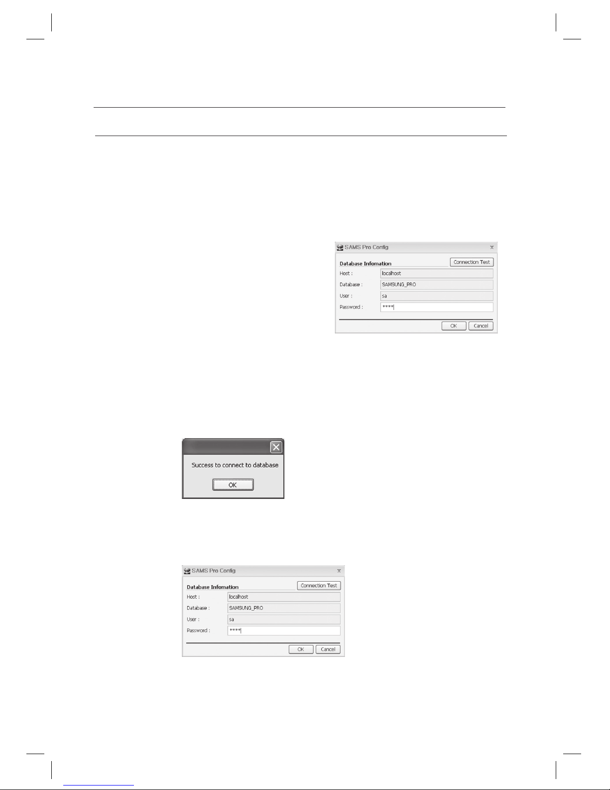
Run [Start] > [All Programs] > [SAMSUNG] > [SAMS Pro] > [SAMS Pro Confi g].
Check the default values of [Host:], [Database:], and [User:]. Enter the password used in the installation of
Microsoft SQL Server 2005 Express Edition into the password fi eld.
For [Host:] fi eld, enter the database server’s name. In
case the database server is installed on the same
computer, enter localhost. Otherwise, enter the IP
address of the computer installed with the database
server. If an instance had been created during the
database server installation, enter localhost\instance
name for the host name. For example, if the instance
name was SQLEXPRESS, enter localhost\
SQLEXPRESS into the host name fi eld.
For [Database:] fi eld, enter the database name used by the
SAMS Pro. Use the default database name SAMSUNG_PRO.
For [User:] fi eld, enter the login ID to access the Microsoft SQL Server 2005 Express Edition. Use the default sa.
For [Password:] fi eld, enter the password used in the installation of Microsoft SQL Server 2005 Express
Edition into the password fi eld.
Click [Connection Test] to test the database connection. Click [OK].
If the Connection Test fails, it means the database connection information is not properly confi gured. If this is the
case, check if Host, User and Password are correct.
Click [OK].
1.
2.
•
•
•
•
3.
J
4.
confi gurations
Page 39
English Englis_ English _39
CONFIGURATIONS
CONFIGURING SAMS COMMUNICATION SERVER PRO DATABASE CONNECTION
When the SAMS Communication Server Pro is installed for the fi rst time, database server connection should be confi gured.
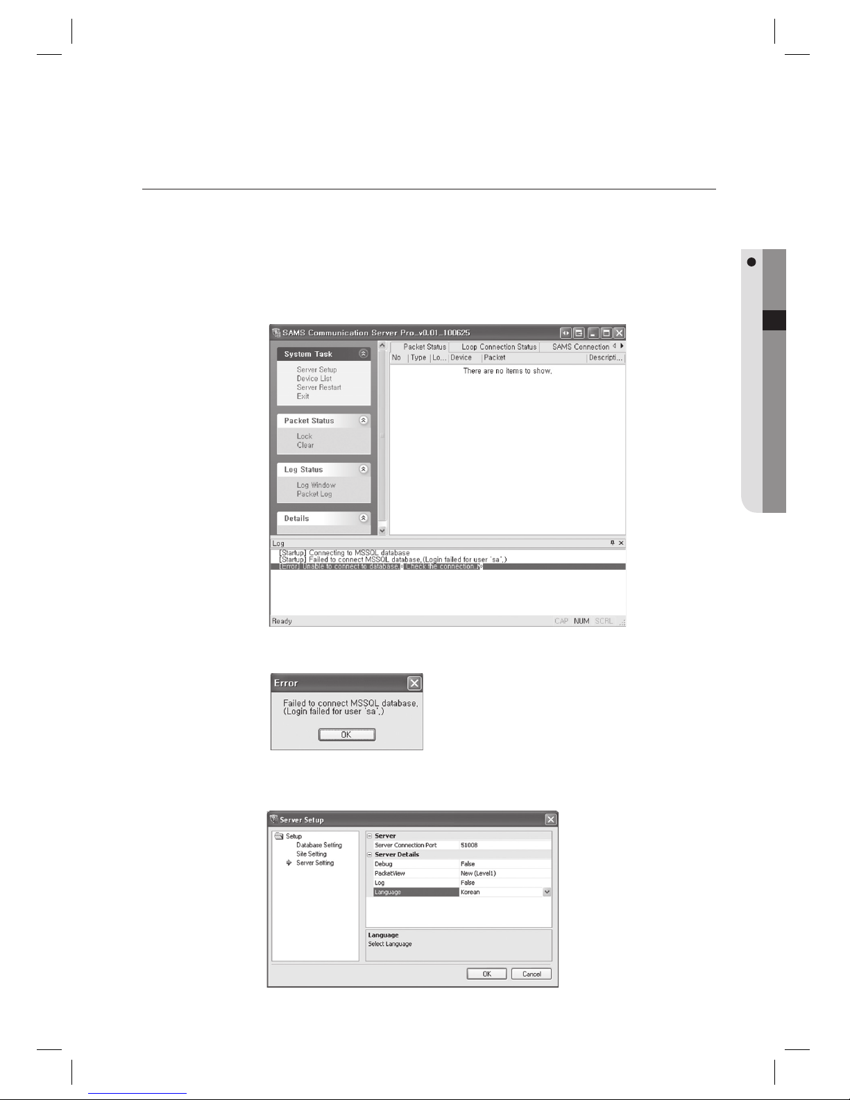
Run [Start] > [All Programs] > [SAMSUNG] > [SAMS Communication Server Pro] > [SAMS Communication
Server Pro].
Click [Server Setup] in the [System Task].
Since the database connection is not confi gured, the below message appears. Click [OK].
You can select the language in the right pane after selecting the [Server Setting] submenu in the [Setup].
(Supported language: English, Korean).
1.
2.
3.
4.
Page 40
40_ confi gurations
confi gurations
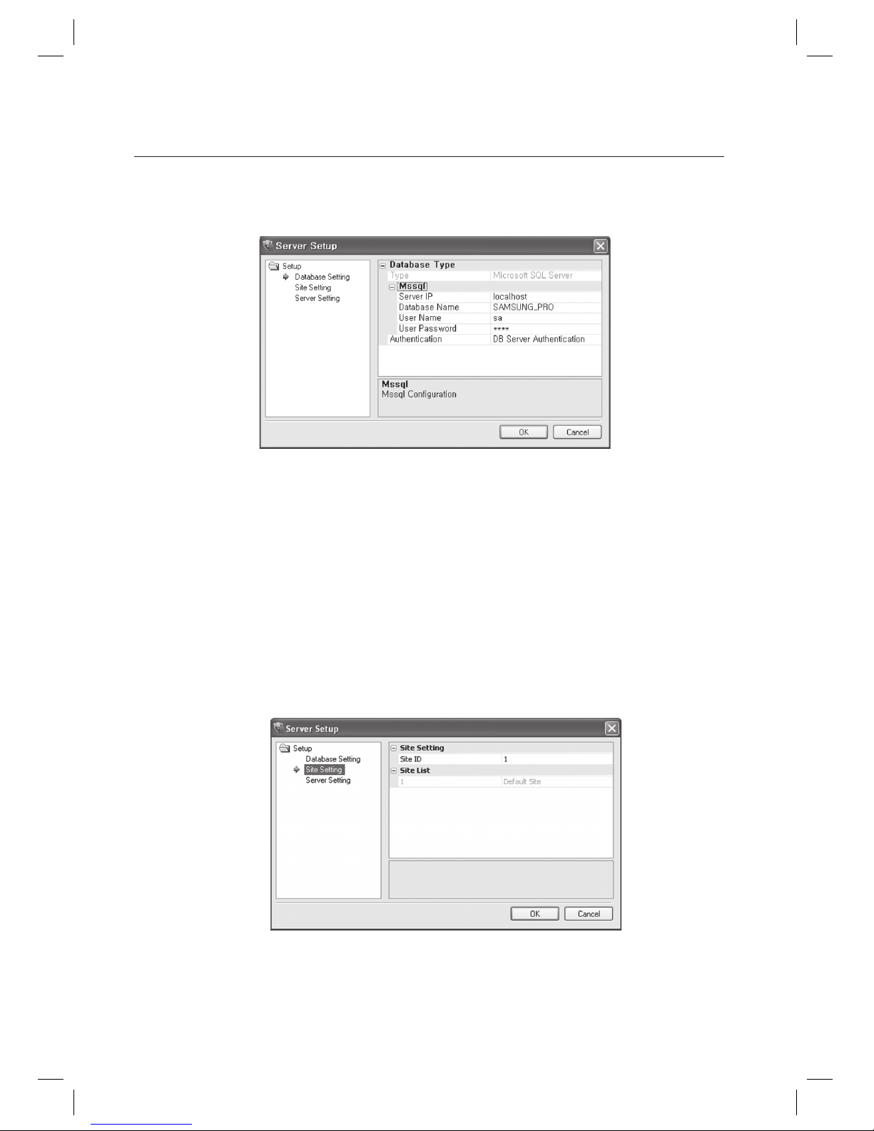
Click Mssql in the right pane after selecting the [Database Setting] submenu in the [Setup].
Check the default values of [Server IP], [Database Name], and [User Name]. Enter the password used in the
installation of Microsoft SQL Server 2005 Express Edition into the [User Password] fi eld.
For [Server IP] fi eld, enter the database server’s name. In case the database server is installed on the same
computer, enter localhost. Otherwise, enter the IP address of the computer installed with the database
server. If an instance had been created during the database server installation, enter localhost\instance name
for the host name. For example, if the instance name was SQLEXPRESS, enter localhost\SQLEXPRESS into
the host name fi eld.
For [Database Name] fi eld, enter the database name used by the SAMS Pro. Use the default database name
SAMSUNG_PRO.
For [User Name] fi eld, enter the login ID to access the Microsoft SQL Server 2005 Express Edition. Use the
default sa.
For [Authentication] fi eld, select the DB Server Authentication option.
Select the [Site Setting] in [Setup]. Site List that is already registered is displayed on the right pane. Enter the
code 1 into the Site ID fi eld of the Default Site, which is the default site. If there are multiple site lists, set the site
code of the desired site which will be communicating with SAMS Communication Server Pro.
Once completed with all confi gurations, click [OK].
5.
•
•
•
•
6.
7.
Page 41
English Englis_ English _41
CONFIGURATIONS
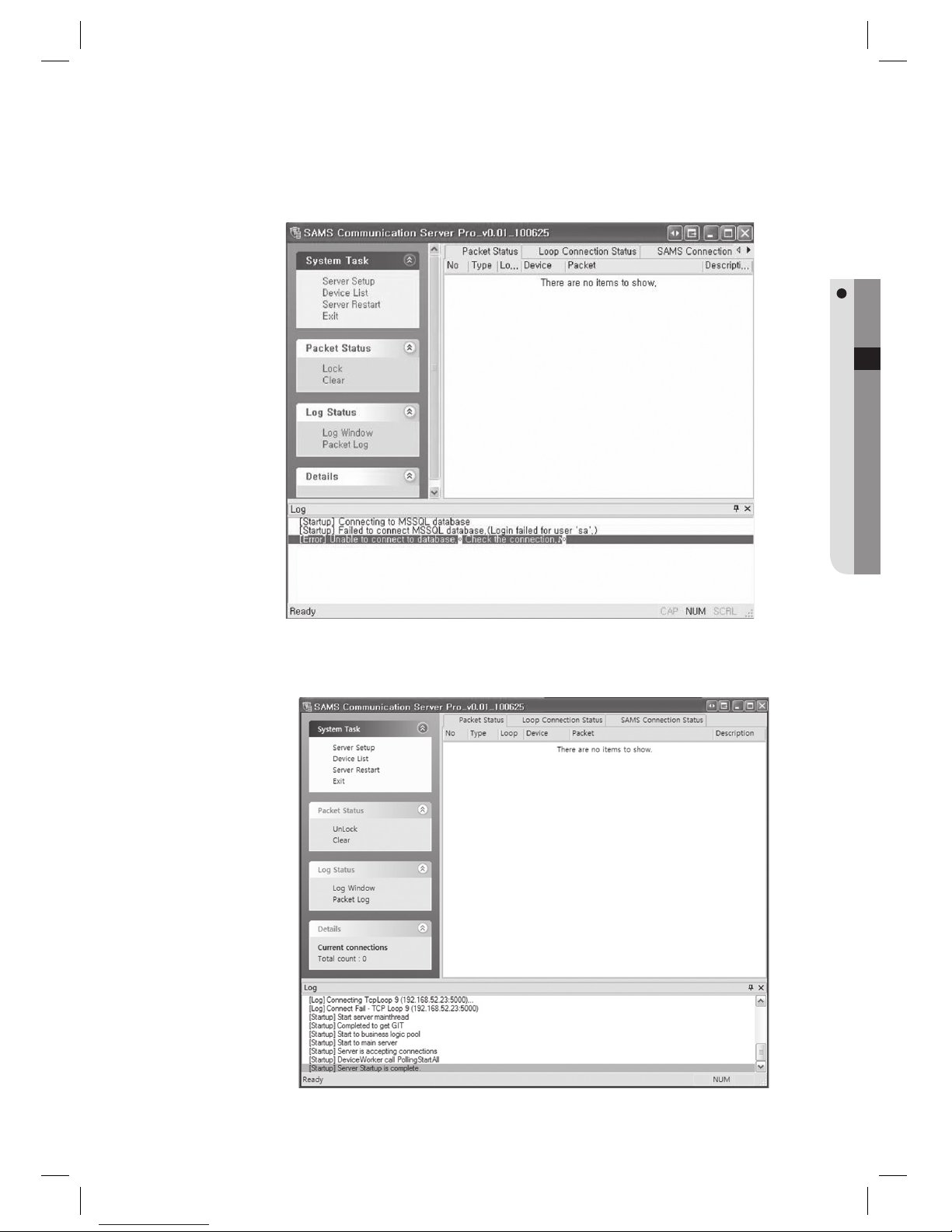
Click [Server Restart] in the [System Task].
The SAMS Communication Server Pro restarts and the changes made for database connection and language
settings are applied.
8.
9.
Page 42
42_ logging in & initial setup
LOGGING IN SAMS PRO
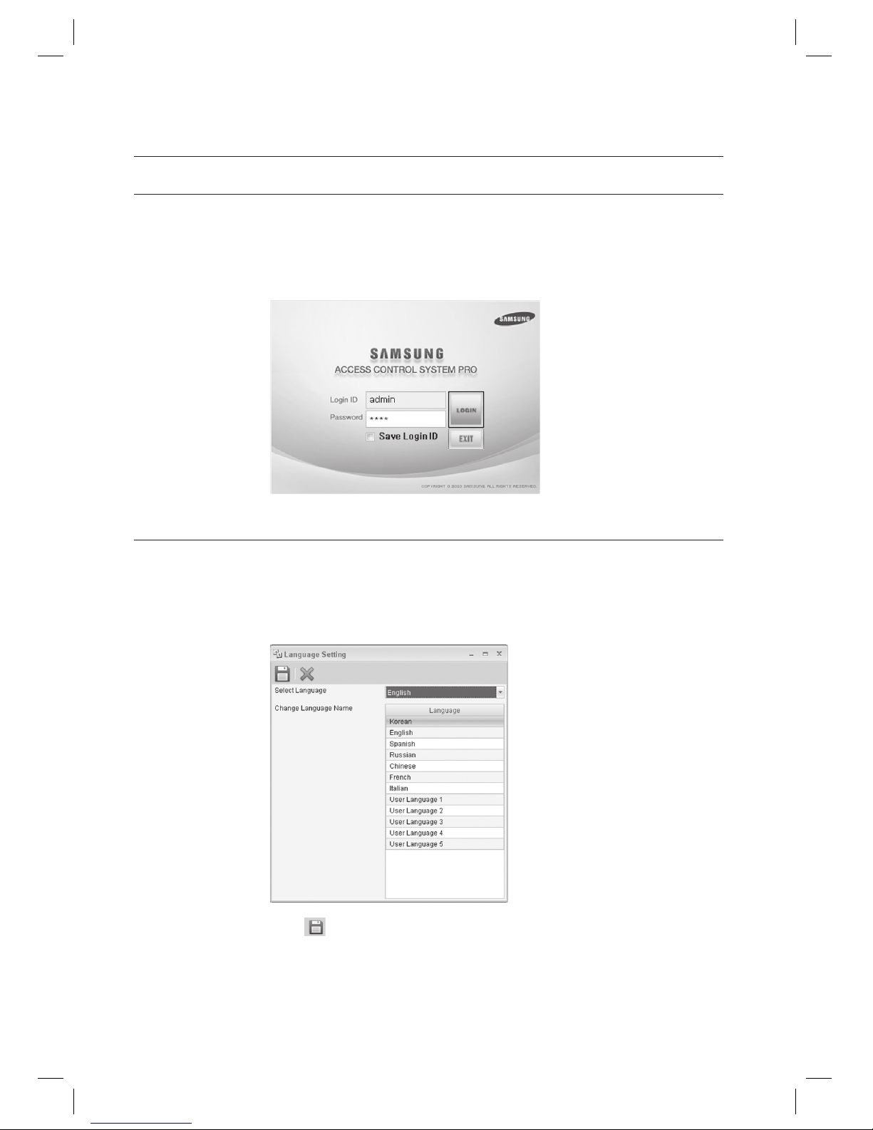
Run [Start] > [All Programs] > [SAMSUNG] > [SAMS Pro] > [SAMS Pro].
Enter “admin” for the [Login ID], and “4321” for the [Password], and click [LOGIN].
LANGUAGE SETUP
From the upper menu, select [Tool] > [Language Setting].
Select [English] from [Select Language].
From the tool bar, click <
>.
1.
2.
1.
2.
3.
logging in & initial setup
Page 43
English Englis_ English _43
LOGGING IN & INITIAL SETUP
BUILDING-FLOOR SETTING
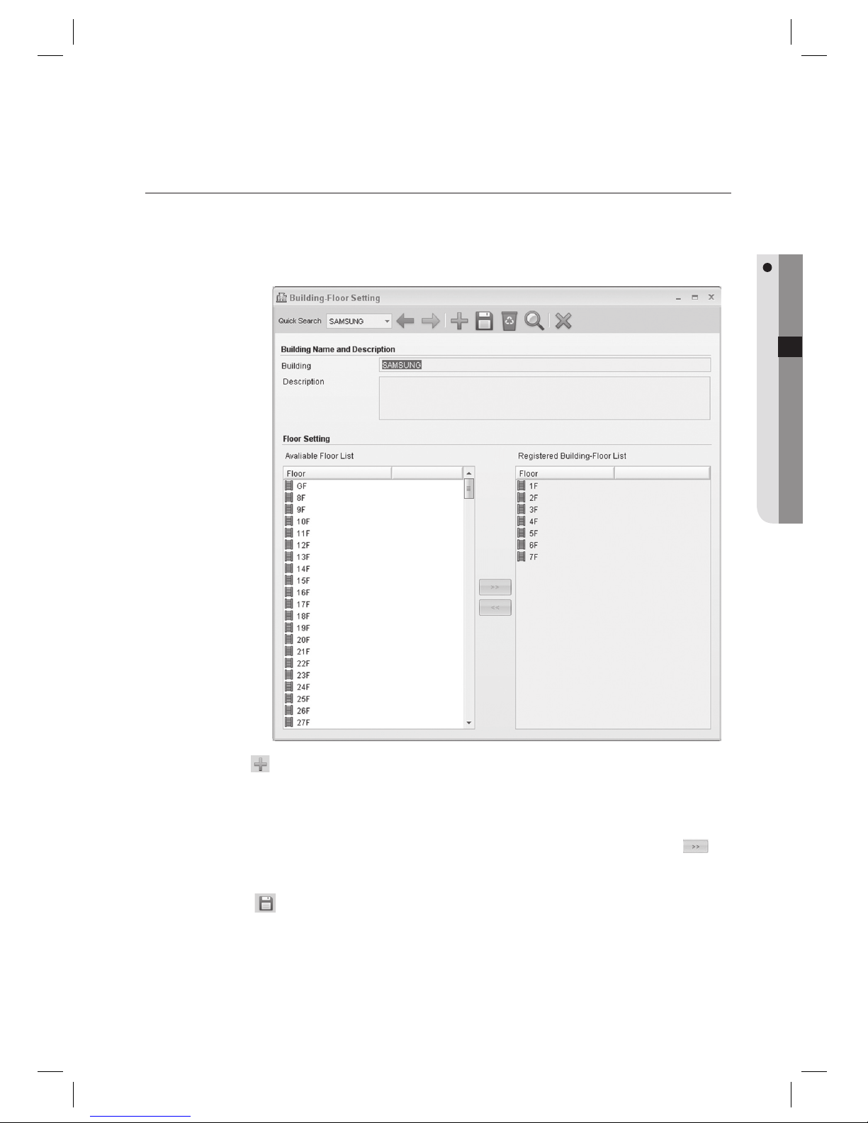
Registers the building’s name and fl oor.
(This is not available in SAMS Pro Lite.)
From the upper menu, select [System Management] > [Building-Floor Setting].
Click Add <
> in the tool bar.
Provide the building name in the [Building] input box.
From the left [Avaliable Floor List], select a fl oor to be included in the building and use the right arrow <
>
button to move to the right. Or use the mouse to drag and drop an item.
Click Save <
> in the tool bar.
An input box with yellow background indicates that the fi eld is required.
1.
2.
3.
4.
5.
J
Page 44
44_ logging in & initial setup
logging in & initial setup
SITE SETTING
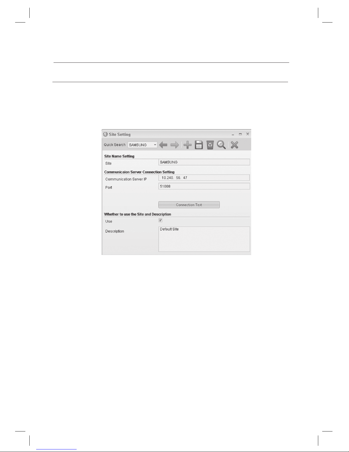
This will guide you through connection between PC that has installed SMAS Pro and communication server; for
SAMS Pro Lite, you can select a site to monitor from a list of the specifi ed sites.
Up to 10 sites can be added to the SAMS Pro, and each site requires its own Communication Server.
From the upper menu, select [System Management] > [Site Setting].
When adding a site, use Quick Find instead of Add for editing site information, since a site has default setting
values. Click [Quick Search] on the top left corner and select the default value Default Site.
If a site has been newly added, Site Setting of SAMS Communication Server Pro should be done again.
With SAMS Pro Lite, you can not register a new site or delete an existing one.
Edit [Site].
[Communication Server IP]: Enter the IP address of the computer that is installed with SAMS Communication
Server Pro.
Check the port. It is recommended to use the default 51008.
1.
2.
J
3.
4.
5.
Page 45
English Englis_ English _45
LOGGING IN & INITIAL SETUP
If this port is changed, communication to the SAMS Communication Server Pro may not establish. If changed this
port, make the same change to the SAMS Communication Server Pro too.
Check whether the [Use] is checked.
If [Use] is not checked, communication to the corresponding communication server will not establish. This can be
used when intended not to connect temporarily to a specifi c server.
By using the [Connection Test], check if SAMS Pro properly connects to the SAMS Communication Server Pro.
Click Save <
> in the tool bar.
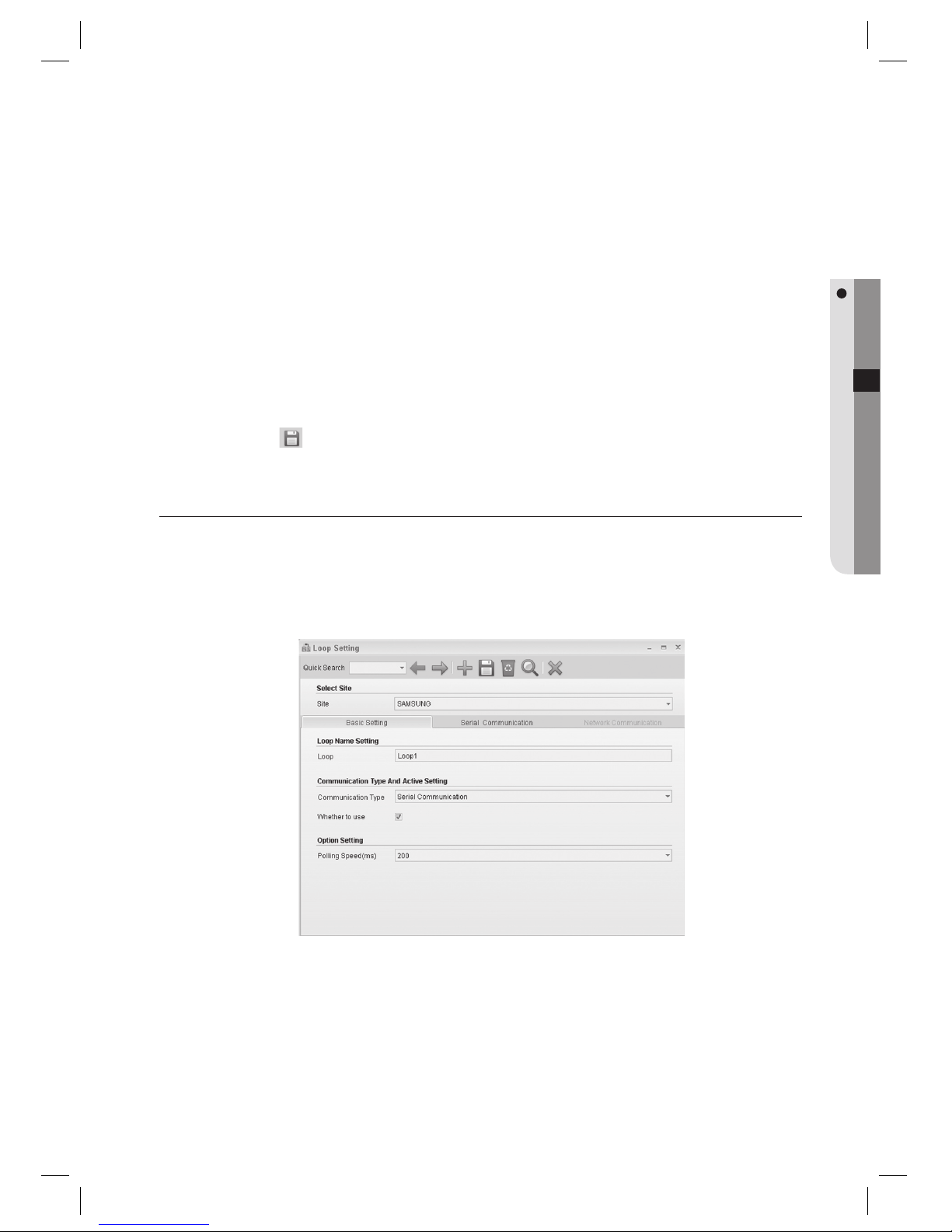
LOOP SETTING (SERIAL COMMUNICATION)
Up to 100 loops can be assigned for each site, up to 32 controllers can be connected to each loop in serial
communications (may vary depending on controller specifi cations). For networked communications, one loop can be
connected to one controller. (This is not available in SAMS Pro Lite.)
From the upper menu, select [System Management] > [Loop Setting].
Select a [Site].
Enter the [Loop].
Select a [Communication Type]. Select [Serial Communication] if communication to the device is serial.
Check [Whether to use].
J
6.
J
7.
8.
1.
2.
3.
4.
5.
Page 46
46_ logging in & initial setup
logging in & initial setup
If unchecked, devices connected to the selected loop will not communicate.
Set the interval of polling in [Polling Speed (ms)]. Use the default 200.
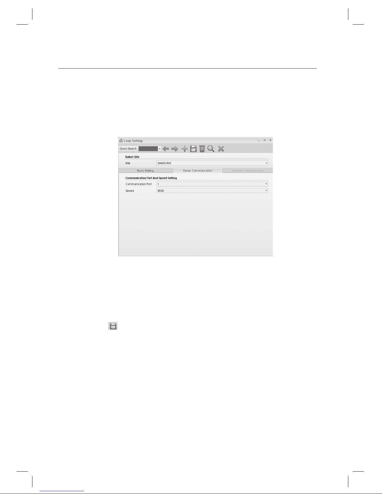
Move to the [Serial Communication] tab.
Set the [Communication Port].
Set the [Speed].
Communication speed varies depending on devices. Since the communication speed may vary depending on
devices, refer to the product documentation of each device for proper setting.
Click Save < > in the tool bar.
When “Do you want to restart the communication server?” message appears, click [Yes(Y)].
If SAMS Communication Server Pro is running and site confi guration is properly done, communication server will
restart normally. If SAMS Communication Server Pro is not running or the site information is improperly confi gured,
communication server may fail to restart.
J
6.
7.
8.
9.
J
10.
11.
J
Page 47
English Englis_ English _47
LOGGING IN & INITIAL SETUP
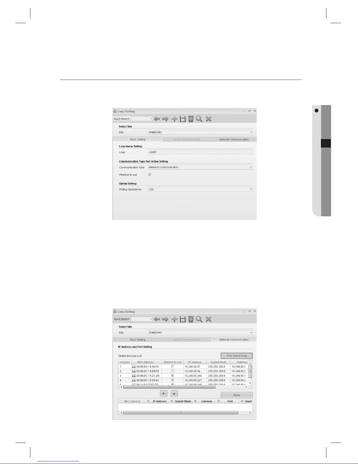
LOOP SETTING (NETWORK COMMUNICATION)
(This is not available in SAMS Pro Lite.)
From the upper menu, select [System Management] > [Loop Setting].
Select a [Site].
Enter the [Loop].
Select the [Communication Type]. Select [Network Communication] for TCP/IP networking.
Check [Whether to use].
If unchecked, devices connected to the selected loop will not communicate.
Set the interval of polling in [Polling Speed (ms)]. Use the default 200.
Move to the [Network Communication] tab.
1.
2.
3.
4.
5.
J
6.
7.
Page 48

48_ logging in & initial setup
logging in & initial setup
Click [Auto Search Loop].
Searches and displays all devices found in the local network. Devices already added are indicated as checked in the
Whether to use column.
If the operating system is Windows Vista, Auto Search Loop function requires disabling the Windows Firewall.
(Select the [Exception] tab in [Control Panel] > [Security Center] > [Windows Firewall]. Click [Add Programs] to install
SAMS Pro.)
Select a device to be added to the loop from the search result and use the down arrow key < > to move to
the bottom. Devices added into the bottom list are registered as having the same site with different loop. Edit
the network properties for the added device, such as IP address, subnet mask, gateway, port number and
baud rate.
Column Name Descriptions
IP address
Enter the IP address of the added device.
Subnet Mask
Enter the Subnet Mask of the added device.
Gateway
Enter the Gateway address of the added device.
Port
Enter the port number for the communication with the added device. It is recommended to use the default 5000.
Baud Rate
Enter the baud rate of the network converter, which means communication speed.
Click [Apply] to apply the changes.
Click Save <
> in the tool bar.
When “Do you want to restart the communication server?” message appears, click [Yes(Y)].
If SAMS Communication Server Pro is running and site confi guration is properly done, communication server will
restart normally. If SAMS Communication Server Pro is not running or the site information is improperly confi gured,
communication server may fail to restart.
8.
J
9.
10.
11.
12.
J
Page 49
English Englis_ English _49
LOGGING IN & INITIAL SETUP
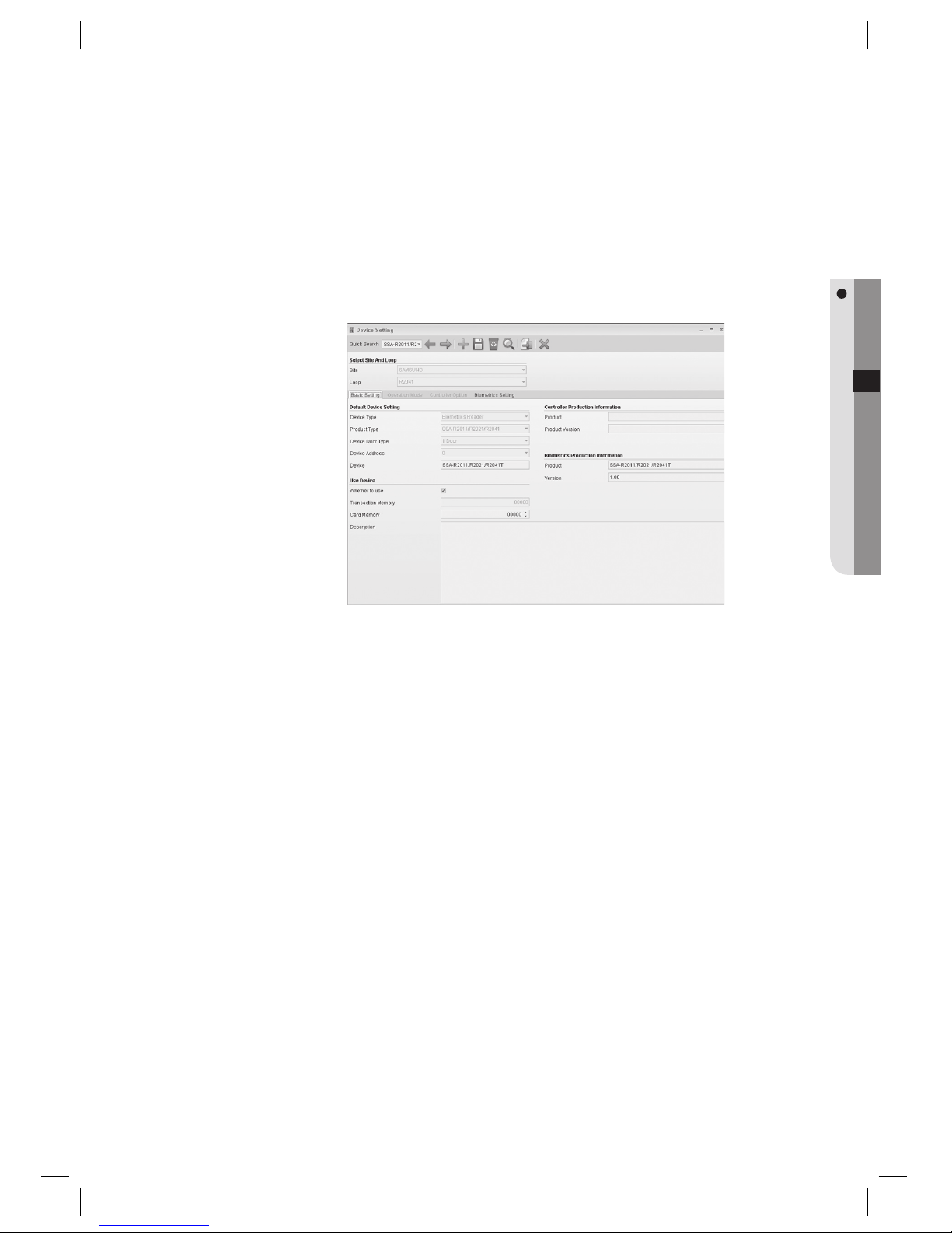
DEVICE SETTING
For serial communications, confi gure devices connected to each loop. For network communications, confi gure one
connected device for each loop. (This is not available in SAMS Pro Lite.)
From the upper menu, select [System Management] > [Device Setting].
Select a [Site].
Select a [Loop].
Select a [Device Type]. Select [Controller] for access controller device, or select [Biometrics Reader] for
biometrics/fi ngerprint readers.
SSA-P102, SSA-P40x, SSA-S21xx, SSA-S30xx series products are controllers, and SSA-R20xx series products are
biometrics readers.
Select the product type for the device to be confi gured in [Product Type].
Select [Device Door Type]. Door Type varies depending on the devices.
SSA-P102, SSA-S21xx, SSA-S30xx series products are 1-door type. SSA-P40x series products are 2~4 Door type.
Select the [Device Address]. Each controller has its own address for communication.
Setting the communication address differs from product to product. For setting the device’s communication address,
refer to the product documentation for further details.
Note that communication addresses confi gured in SAMS Pro and corresponding device must match for proper
communication between them.
1.
2.
3.
4.
J
5.
6.
J
7.
J
Page 50
50_ logging in & initial setup
logging in & initial setup
Enter the [Device].
Check [Whether to use].
Click Save <
> in the tool bar.
When “Do you want to restart the communication server?” message appears, click [Yes(Y)].
If SAMS Communication Server Pro is running and site confi guration is properly done, communication server will
restart normally. If SAMS Communication Server Pro is not running or the site information is improperly confi gured,
communication server may fail to restart.
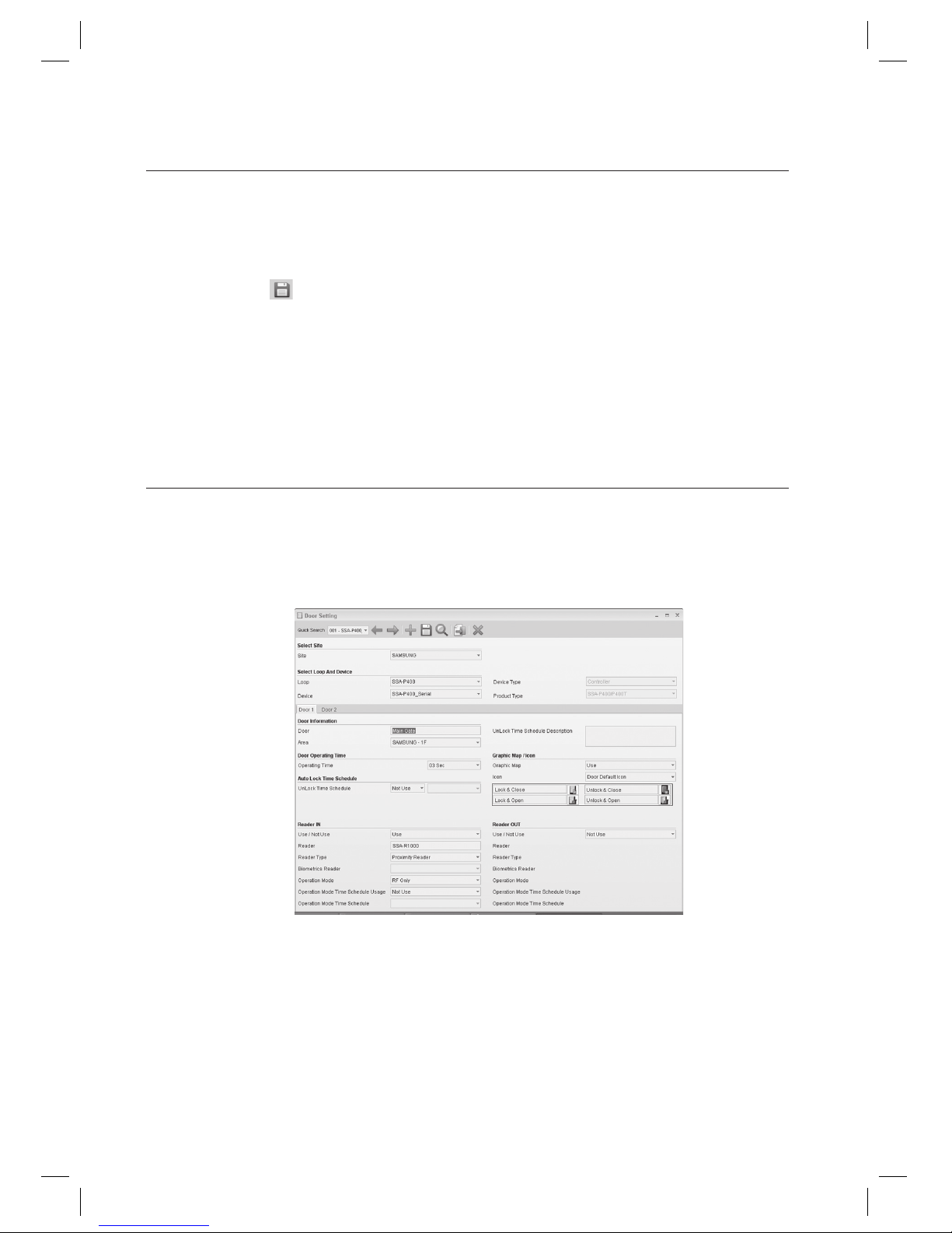
DOOR SETTING
Select the site and loop from registered list and apply to a door.
(This is not available in SAMS Pro Lite.)
From the upper menu, select [System Management] > [Door Setting].
Select a [Site].
Select a [Loop].
Select a [Device]. According to the selected device’s type, number of door tabs may vary.
When selected a 4-Door device, there will be 4 door setting tabs appeared.
Enter the [Door].
8.
9.
10.
11.
J
1.
2.
3.
4.
5.
Page 51
English Englis_ English _51
LOGGING IN & INITIAL SETUP
Select [Area].
Set [Reader IN] and [Reader OUT]. If reader device is installed only for entering, set [Reader IN] only.
Set whether to use or not for each reader in [Use / Not Use] fi eld.
Enter the [Reader].
Select a [Reader Type].
For SSA-R1xxx series, select Proximity Reader. For SSA-S21xx and SSA-S30xx series products too, select Proximity
Reader since these Standalone controllers have built-in proximity readers. For SSA-R2000/2001, select Proximity
Reader+Keypad. For SSA-R2010/R2020/R2040/R2011/R2021/R2041 products, select Biometrics Reader.
Click Save < > in the tool bar.
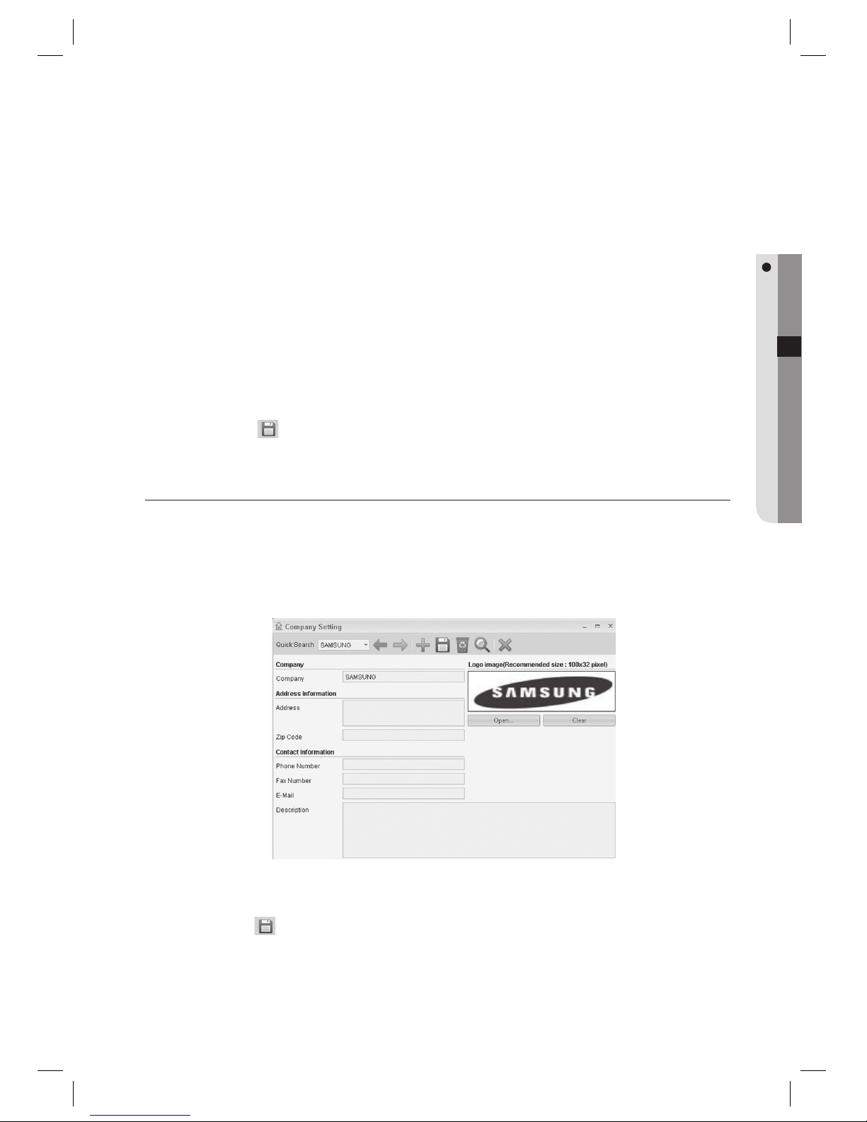
COMPANY SETTING
As additional information for each ID registration, it is required information. All information fi elds other than the company
name are additional and optional.
The company name will be the key fi eld for the [Access Group] confi guration.
From the upper menu, select [Operation Management] > [Company Setting].
Enter the [Company]. You can add a logo for the company information.
Click Save <
> in the tool bar.
6.
7.
8.
9.
J
10.
1.
2.
3.
Page 52
52_ logging in & initial setup
logging in & initial setup
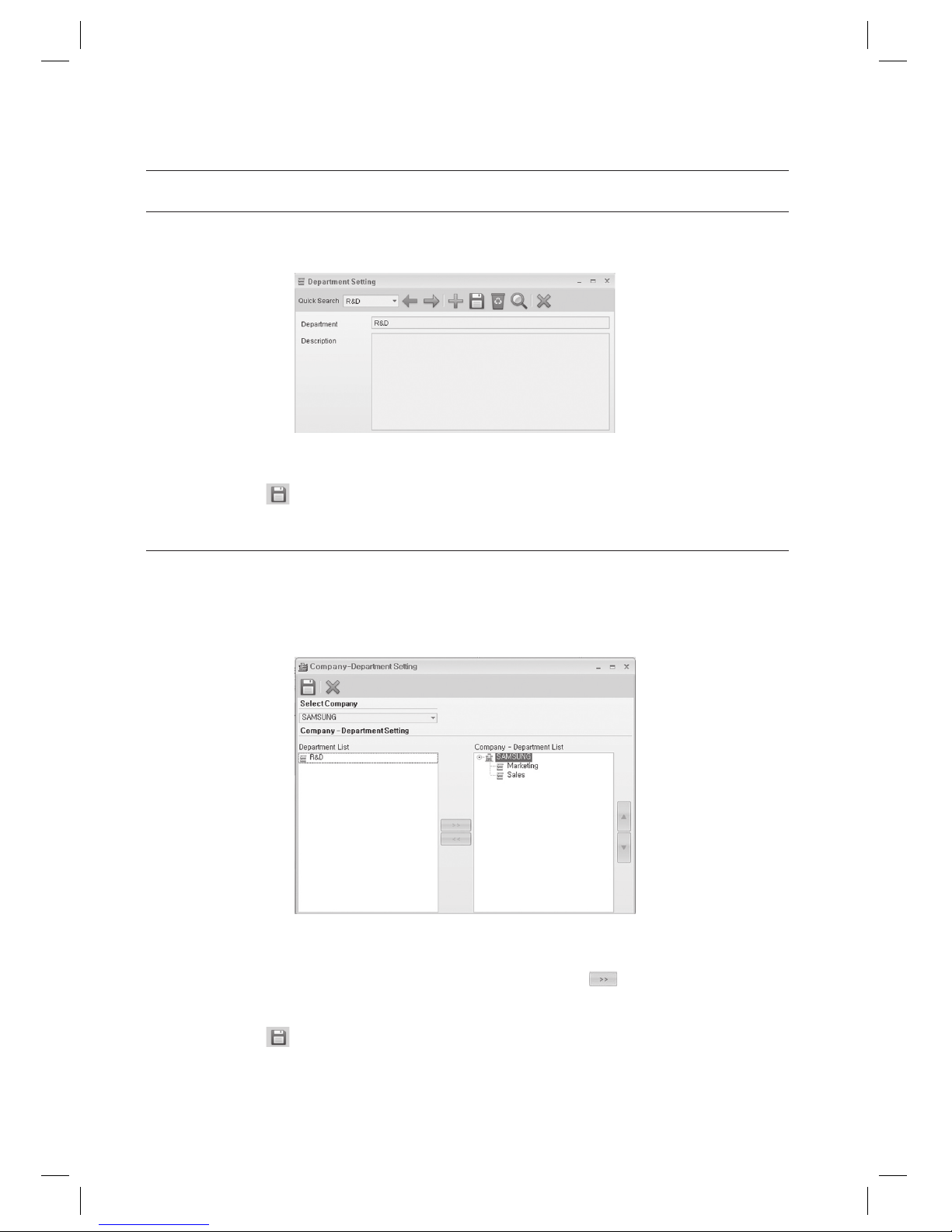
DEPARTMENT SETTING
From the upper menu, select [Operation Management] > [Department Setting].
Enter the [Department].
Click Save <
> in the tool bar.
COMPANY-DEPARTMENT SETTING
Specify departments to use for each registered company.
You can select departments for each registered company as necessary.
From the upper menu, select [Operation Management] > [Company-Department Setting].
Select a company in the [Select Company] list box.
Select a department in the [Department List] and use the right arrow key <
> to move to the right
[Company-Department List].
Click Save <
> in the tool bar.
1.
2.
3.
1.
2.
3.
4.
Page 53
English Englis_ English _53
LOGGING IN & INITIAL SETUP
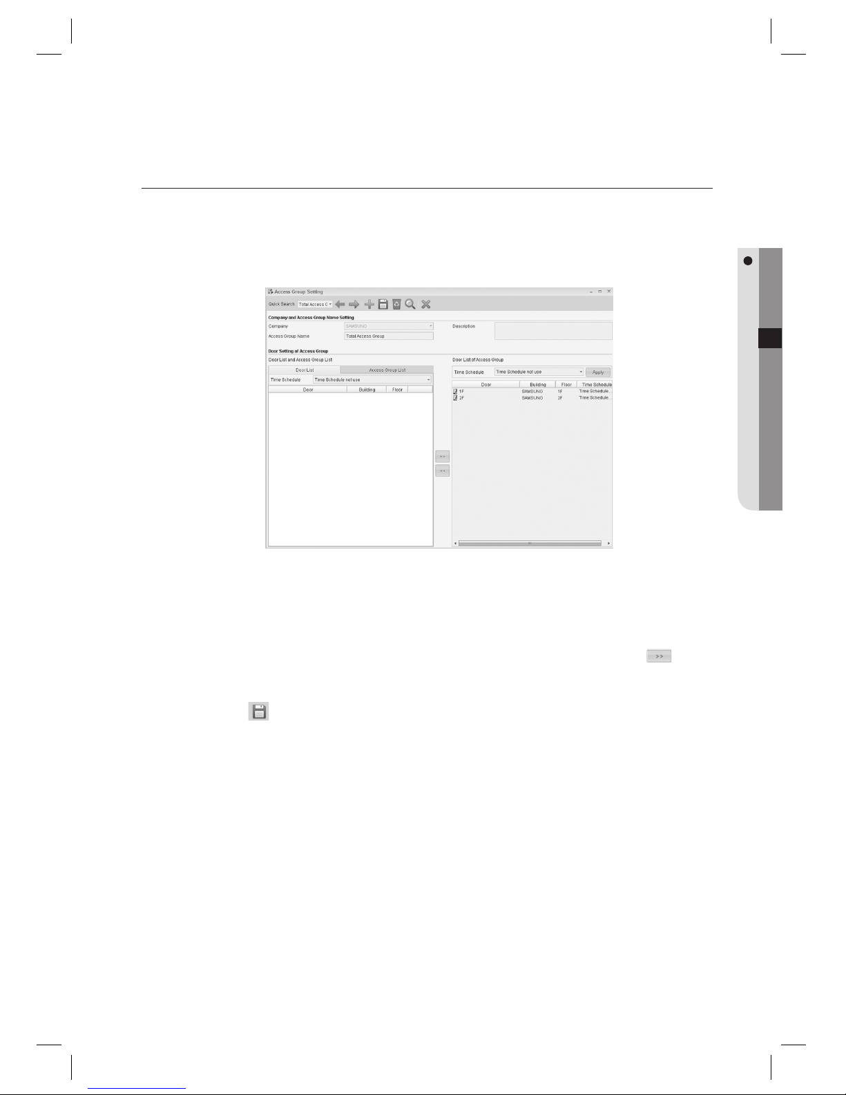
ACCESS GROUP SETTING
Doors registered in [Door Setting] can be assigned to [Access Group] as authorized for accessing.
Each individual ID can belong to [Access Group], which is a required fi eld for ID registration.
From the upper menu, select [Access Control] > [Access Group Setting].
Select a [Company].
Enter the [Access Group Name].
Select a door to be granted to the access group from the [Door List] and use the right arrow key <
> to
move to the right [Door List of Access Group].
Click Save <
> in the tool bar.
You can confi gure the time schedule of the access group for each door. Grouping multiple access groups is
supported. For further details, refer to the Access Group Setting of Access Control section of this manual.
1.
2.
3.
4.
5.
J
Page 54
54_ logging in & initial setup
logging in & initial setup
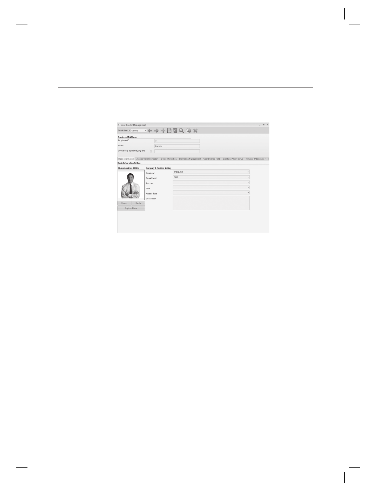
CARD HOLDER MANAGEMENT
You can register an ID and information on each card holder.
From the upper menu, select [Access Control] > [Card Holder Management].
Enter the [Employee ID].
Enter the [Name].
Select a [Company].
Select a [Department].
If there is no company or department name, add in [Operation Management] > [Company Setting] and
[Operation Management] > [Department Setting]. And then set company and department information in
[Operation Management] > [Company-Department Setting].
Add the photo of the user.
You can use bmp, jpg, jpeg, gif, png and wmf fi les. Since too big image fi le may cause delay in registration and
display in monitoring screen, it is recommended to use smaller image fi le. It is recommended to use image fi les in
jpg format. It is recommended to use image fi les of less than 100KB.
1.
2.
3.
4.
5.
J
6.
J
Page 55
English Englis_ English _55
LOGGING IN & INITIAL SETUP
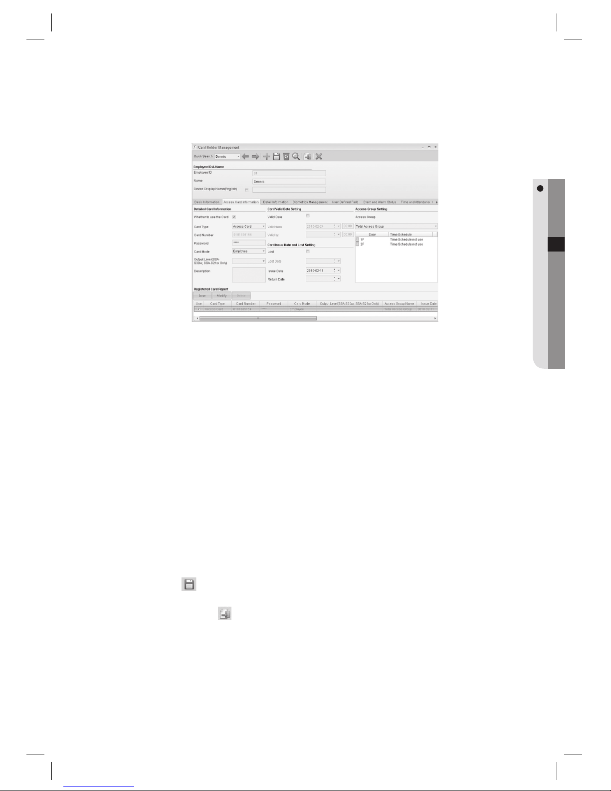
Move to the [Access Card Information] tab.
Select whether to use or not in [Whether to use the Card]. If Whether Use the Card is not checked, accessing
will not be granted.
Select the [Access Card] for [Card Type].
Enter the [Card Number].
Use a number in 4~8 digits or 10 digits. Enter a 4 ~ 8 digit number for 125KHz cards. Enter a 10 digit number for
13.56MHz cards.
Enter the [Password]. Enter a 4-digit password.
Select the [Employee] for [Card Mode].
Select an [Access Group].
Click [Issue] button near the bottom of the screen.
Click Save <
> in the tool bar.
Click Transmit button <
> in the toolbar to send the card information to devices granted to the selected
access group.
7.
8.
9.
10.
J
11.
12.
13.
14.
15.
16.
Page 56
56_ screen composition
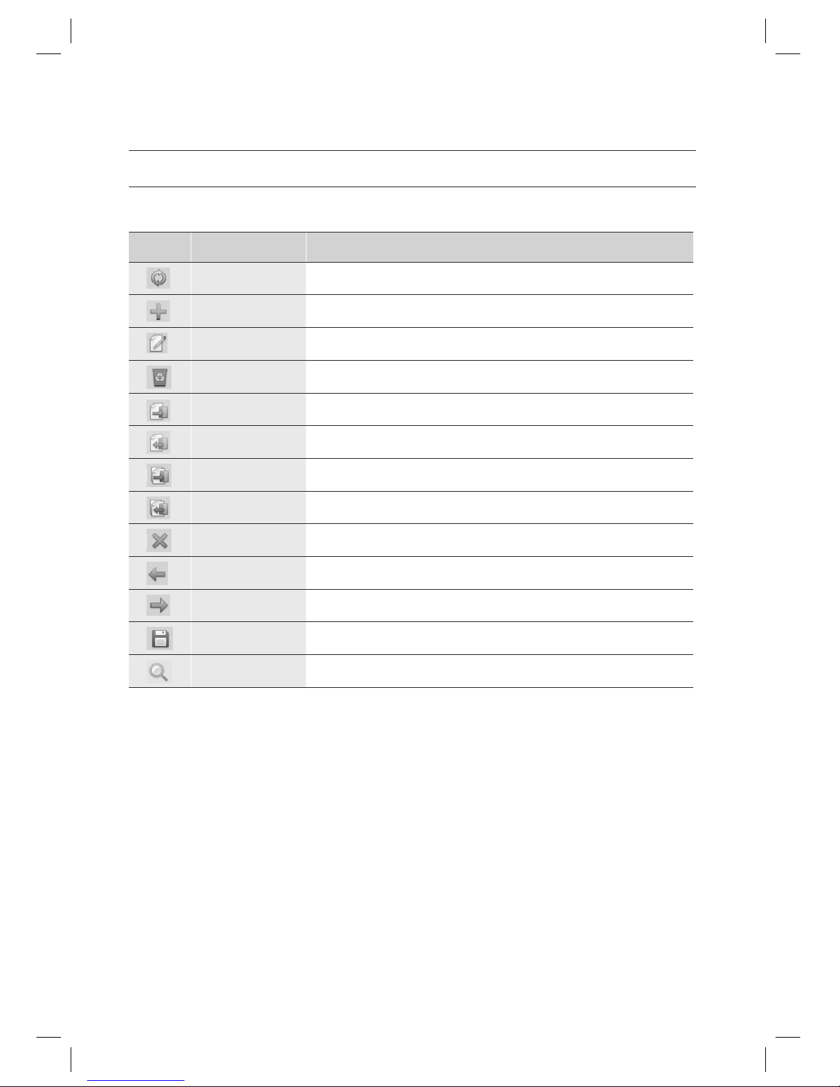
ICONS AND DESCRIPTIONS
Explains icons of SAMS Pro toolbar.
Icon Name Descriptions
Refresh
Refreshes display of connection status with devices.
Add
Used for adding new data.
Edit
Used for editing existing data.
Delete
Used for deleting existing data.
Transmit
Used for sending data to devices.
Receive
Used for receiving data from a device.
Batch transmit
Used for sending data to devices in a batch.
Batch receive
Used for receiving data from a device in a batch.
Close
Close or exit the screen.
Previous
Moves to the previous existing data.
Next
Moves to the next existing data.
Save
Saves the data.
Search
Searches data
screen composition
Page 57
English Englis_ English _57
SCREEN COMPOSITION
MAIN SCREEN
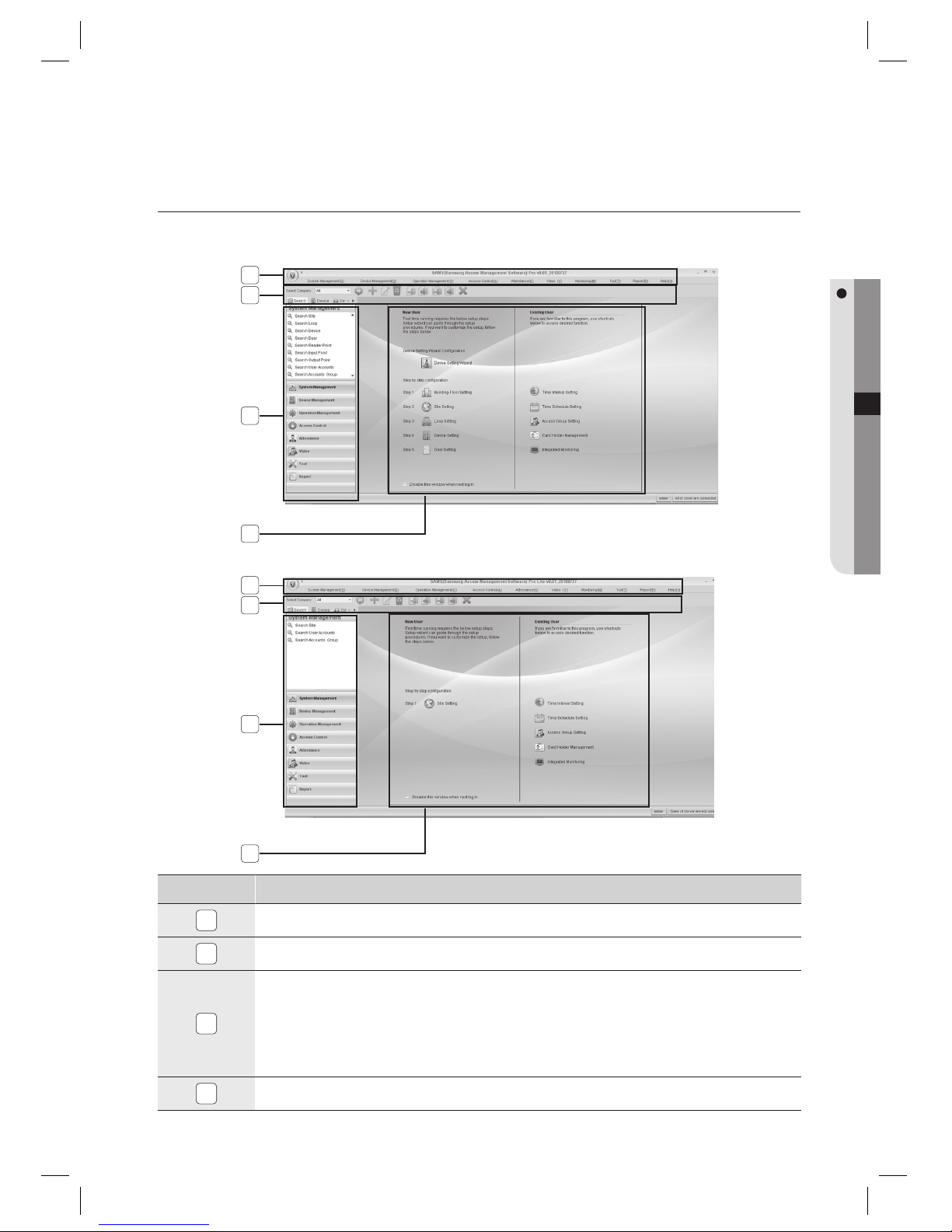
Explains the main screen of the SAMS Pro.
NO. Descriptions
1
The ribbon toolbar is provided for each menu item.
2
Company selection and other functions are provided as buttons.
3
You will fi nd various search options available in the tab area: Search, Device, Connection Status (Device),
Connection Status (DVR & Camera). In the Device tab, you can check the device information in a tree structure.
In the Connection Status (Device) tab, you will be informed of the communication status between connected
devices. In the Connection Status (DVR and camera) tab, you can check the information about the connected
DVRs and cameras as well as information about the communication status between DVRs and cameras. Select
a camera whose live screen you want to monitor and just right-click it.
4
It guides the setup steps to beginners, and shortcuts to frequently used functions to users.
1
2
3
4
< SAMS Pro >
1
3
4
2
< SAMS Pro Lite>
Page 58
58_ system management
DEVICE SETTING WIZARD
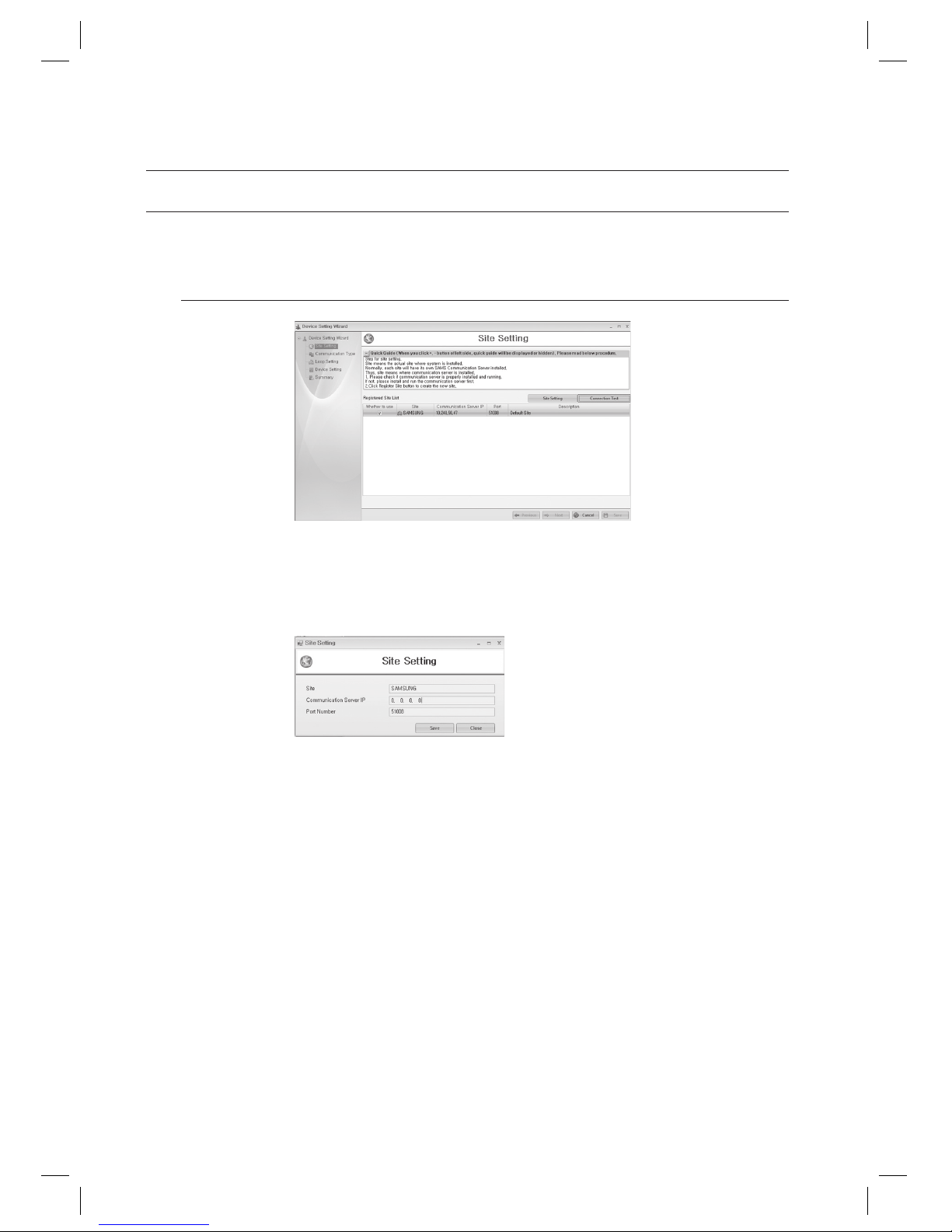
After completing the initial installation, the Device Setting Wizard provides faster and easier device setup steps.
(This is not available in SAMS Pro Lite.)
Device Setting Wizard – Site Setting
Registered Site List: Shows the list of registered sites. Select a site by checking the [Whether to use] checkbox
and use [Connection Test] button to test the connection and move to the next step if successful.
Site Setting: Use this button to setup a new site and register it.
Enter the [Site], and enter the IP address of the computer that is installed with SAMS Communication Server Pro into
the [Communication Server IP].
Use the default [Port Number] which is 51008, and click [Save] button.
Connection Test: Tests whether the connection to the selected site establishes, by using provided IP address
and port number. If error occurs with connection, check IP address, port number are properly set and the
communication server is online.
1.
2.
J
3.
system management
Page 59
English Englis_ English _59
SYSTEM MANAGEMENT
Device Setting Wizard – Communication Type
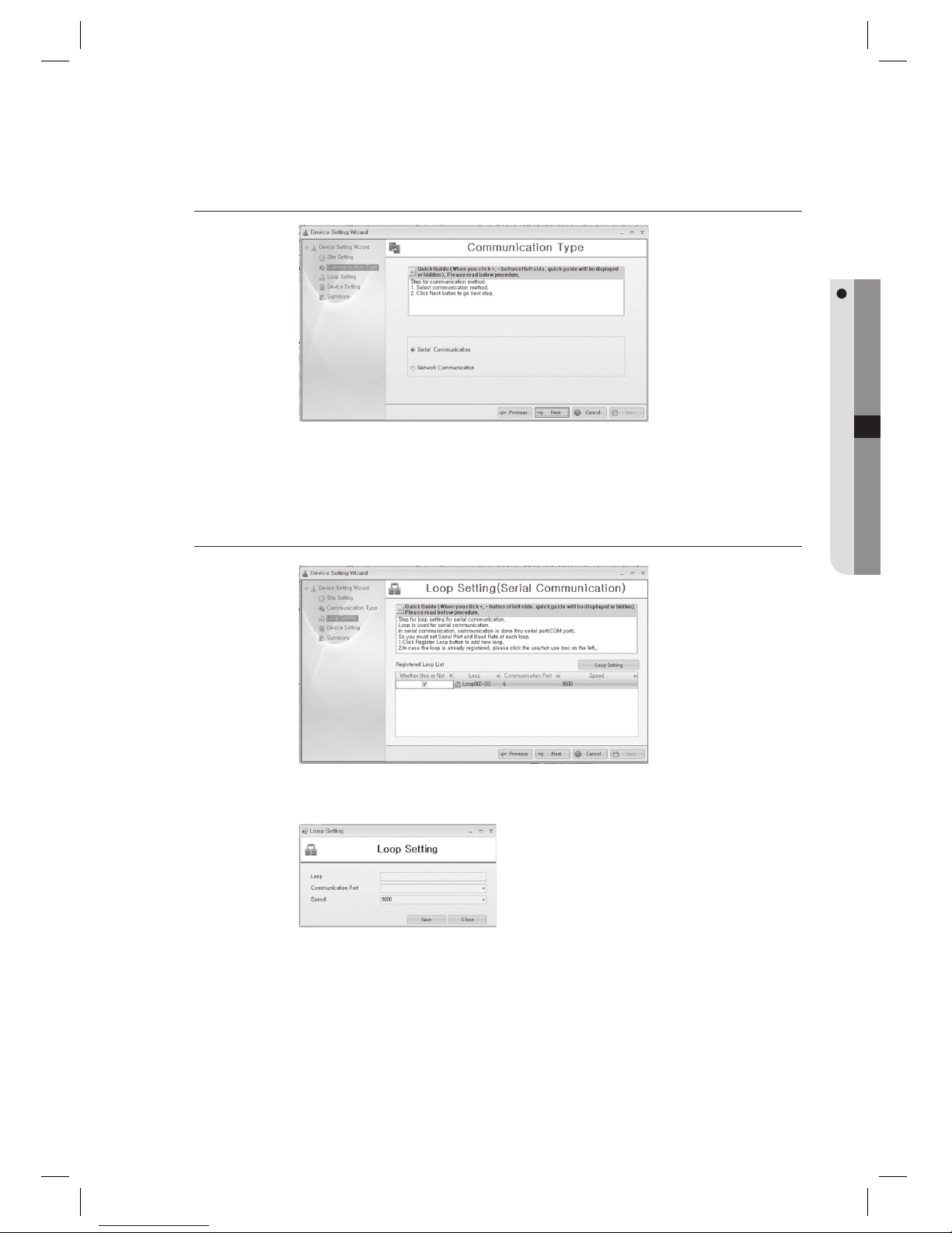
Select the communication type. Select either one of [Serial Communication] or [Network Communication].
Select the desired communication type and click [Next] button.
Device Setting Wizard – Loop Setting (Serial Communication)
This is for serial communication settings. For network communication settings, refer to the Network
Communication section.
Click [Loop Setting] to add a loop. Enter the [Loop]. Enter the [Communication Port] that is used for
communication to the device. Enter the baud rate of the device to [Speed]. Check your device and specify the
value properly, since the baud rate differs from devices. When you complete your selection, press the [Save]
button.
Once completed with adding a loop, select the desired loop and click [Next] button. (When a message of “Do
you want to restart the communication server?” appears, Click [Yes(Y)].)
1.
2.
1.
2.
3.
Page 60
60_ system management
system management
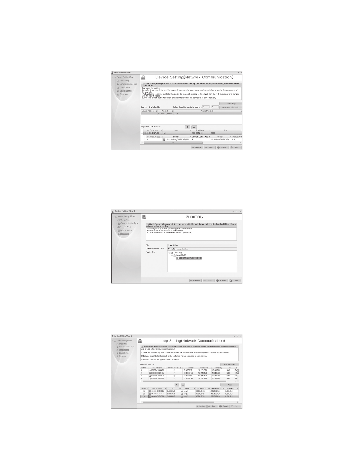
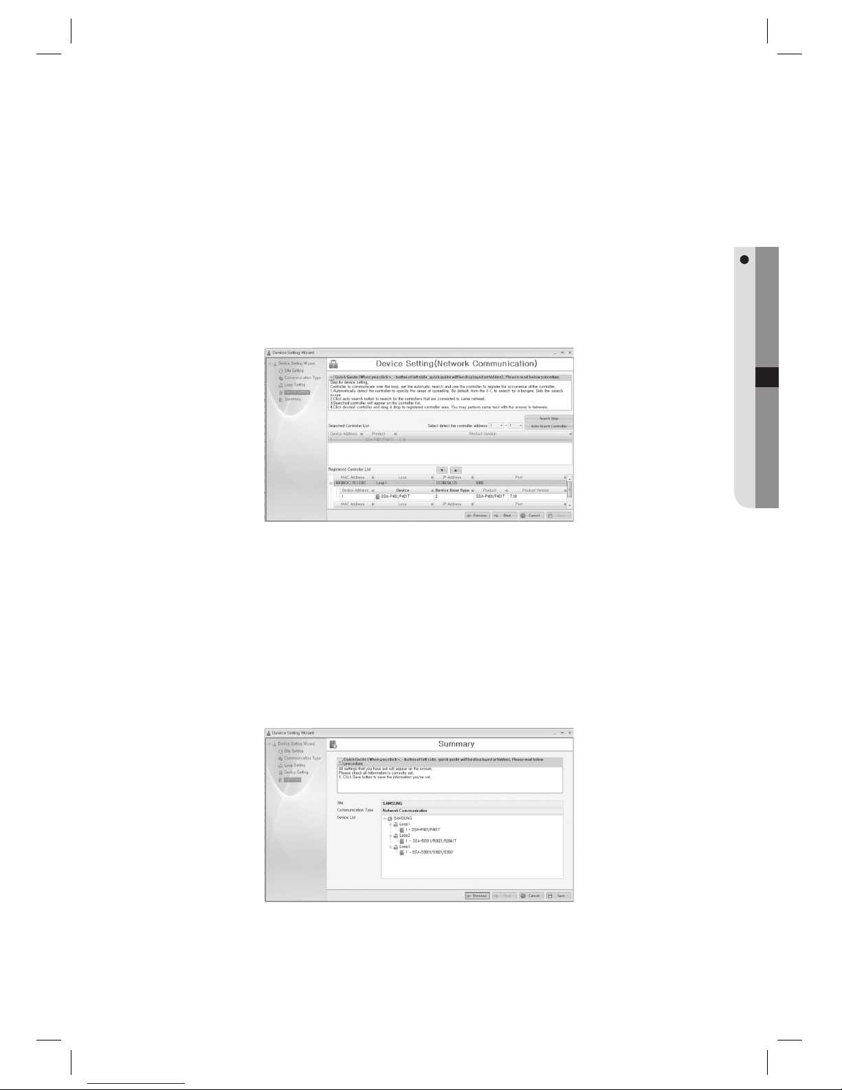
This is a step to confi gure the device settings. Scan for controllers to communicate with via the previously
specifi ed loop and select one to register. Specify the address range for the controllers to scan for. By default,
the automatic scan will check the address range of between 0 and 1. Click [Auto Search Controller] to scan for
controllers within the specifi ed range. The controllers found will be displayed in the [Searched Controller List].
Select a controller to use in the controller list and drag and drop it to the [Registered Controller List] on the
bottom. Or use the triangle or the inverted triangle shaped button to register or delete it. Select the name
column of each controller in the [Registered Controller List] and rename it as necessary. Click [Next] to move to
the next step.
Confi rm the registered information. Check whether the controller setting is properly done, and click [Save] to
fi nish the setting.
Device Setting Wizard – Loop Setting (Network Communication)
4.
5.
Page 61
English Englis_ English _61
SYSTEM MANAGEMENT
This is for network communication settings.
Search controllers connected to the same network that is used by the computer installed with the management
system, and register the controller to be used.
Click [Auto Search Loop] button to search controllers that are connected to the same network. Found
controllers are listed in the [Searched Loop List]. Select the desired controller in the searched list, drag it and
drop into the list box in the bottom. Or you can add or remove controllers by using triangular arrow keys. You
can edit controller information such as the device name and network properties to fi t to the actual network
confi gurations by selecting the corresponding column data. Click [Apply] to apply the changes to the controller.
Click [Next] to move to the next step.
Windows Vista users should release the operation of the fi rewall function as follows:
(Select the [Exception] tab in [Control Panel] > [Security Center] > [Windows Firewall].
Click [Add Programs] to install SAMS Pro.)
This step sets the device properties. Search controllers automatically within the loop previously selected, and
select the controller to be used from the search result. Specify the range of controller address for automatic
search. By default, it is set to address 0 to address 1. Click [Auto Search Controller] button to search
controllers within the specifi ed range. Found controllers are listed in the [Searched Controller List]. Select the
desired controller in the searched list, drag it and drop into the [Registered Controller List] in the bottom. Or
you can add or remove controllers by using triangular arrow keys. Select the Device column in [Registered
Controller List] and edit the name of the controller if required. Click [Next] to move to the next step.
Confi rm the registered information. Check whether the controller setting is properly done, and click [Save] to
fi nish the setting.
1.
2.
3.
J
4.
5.
Page 62
62_ system management
system management
BUILDING-FLOOR SETTING [ADD]
(This is not available in SAMS Pro Lite.)
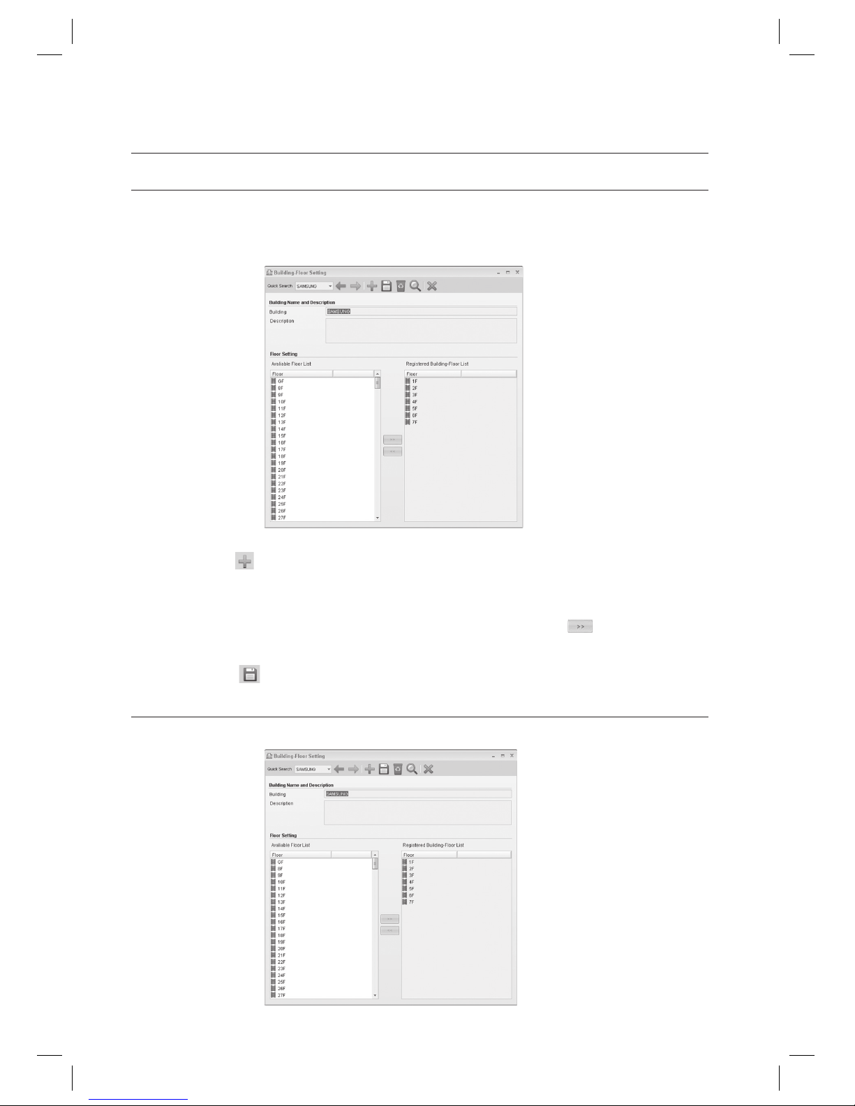
From the upper menu, select [System Management] > [Building-Floor Setting].
Click Add <
> in the tool bar.
Provide the building name in the [Building] input box.
Select a fl oor to be added in the [Available Floor List] and use the right arrow key <
> to move to the right.
Or use the mouse to drag and drop an item.
Click Save <
> in the tool bar.
BUILDING-FLOOR SETTING [EDIT]
(This is not available in SAMS Pro Lite.)
1.
2.
3.
4.
5.
Page 63
English Englis_ English _63
SYSTEM MANAGEMENT
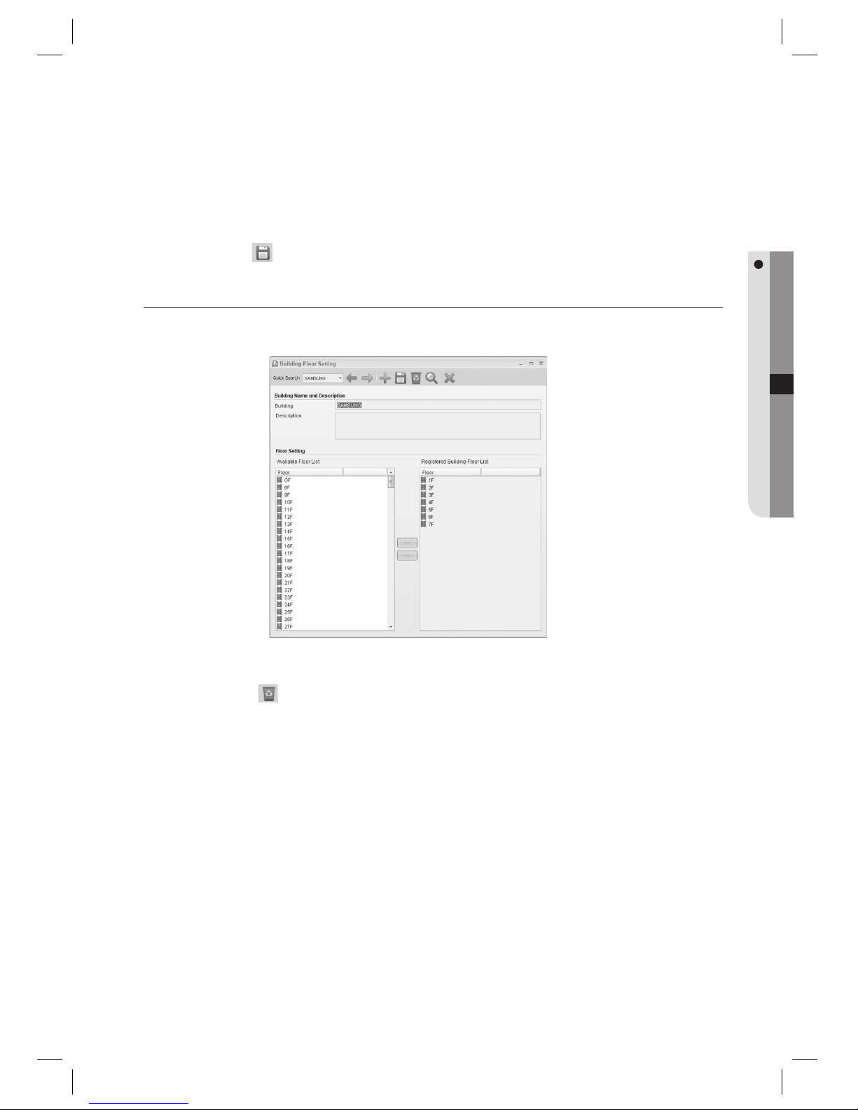
Select an item to change using [Quick Search] in the tool bar.
Selected fl oor is added by moving to the right or deleted by moving to the left.
Click Save <
> in the tool bar.
BUILDING-FLOOR SETTING [DELETE]
(This is not available in SAMS Pro Lite.)
Select an item to delete using [Quick Search] in the tool bar.
Click Delete <
> in the tool bar.
When you are prompted to delete the item, click [Yes].
1.
2.
3.
1.
2.
3.
Page 64
64_ system management
system management
BUILDING-FLOOR SETTING [SEARCH]
(This is not available in SAMS Pro Lite.)
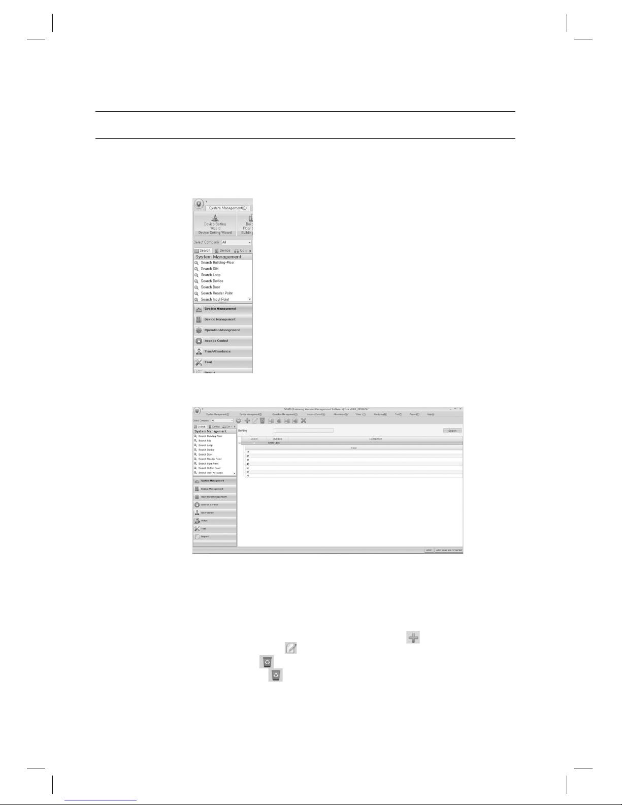
In the left [Search] tab of the main screen, select [System Management] > [Search Building-Floor].
The Building-Floor search result will be displayed in the right pane of the screen.
Provide the search criteria according to the item to fi nd.
Click Search to start searching.
In the search list, you can also add, edit or delete items. From the tool bar, click < > to move to the input
screen. Select a searched item and click <
> to move to the edit (change) screen.
Select a searched item and click <
> to delete it. If you want to delete multiple items at once, check all the items
to delete in the search list and click <
> to delete them all at once.
1.
2.
3.
4.
J
Page 65
English Englis_ English _65
SYSTEM MANAGEMENT
SITE SETTING [ADD]
(This is not available in SAMS Pro Lite.)
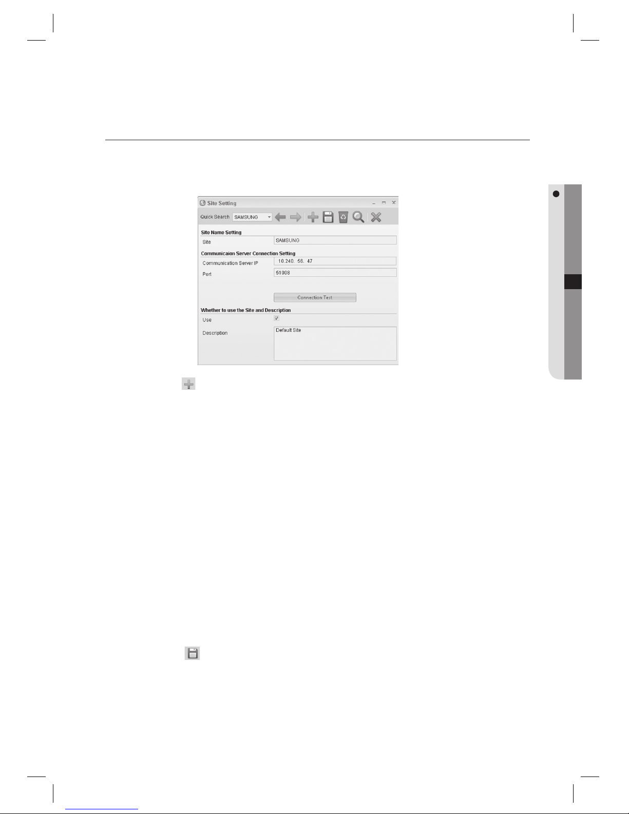
From the upper menu, select [System Management] > [Site Setting].
Click Add < > in the tool bar.
If a site has been newly added, Site Setting of SAMS Communication Server Pro should be done again.
Enter the [Site].
Enter the IP address of the computer that is installed with SAMS Communication Server Pro.
Check the port. It is recommended to use the default 51008.
If this port is changed, communication to the SAMS Communication Server Pro may not establish. If changed this
port, make the same change to the SAMS Communication Server Pro too.
Check whether the [Use] is checked.
If [Use] is not checked, communication to the corresponding communication server will not establish. This can be
used when intended not to connect temporarily to a specifi c server.
By using the [Connection Test], check if SAMS Pro properly connects to the SAMS Communication Server Pro.
Click Save <
> in the tool bar.
1.
2.
J
3.
4.
5.
J
6.
J
7.
8.
Page 66
66_ system management
system management
SITE SETTING [EDIT]
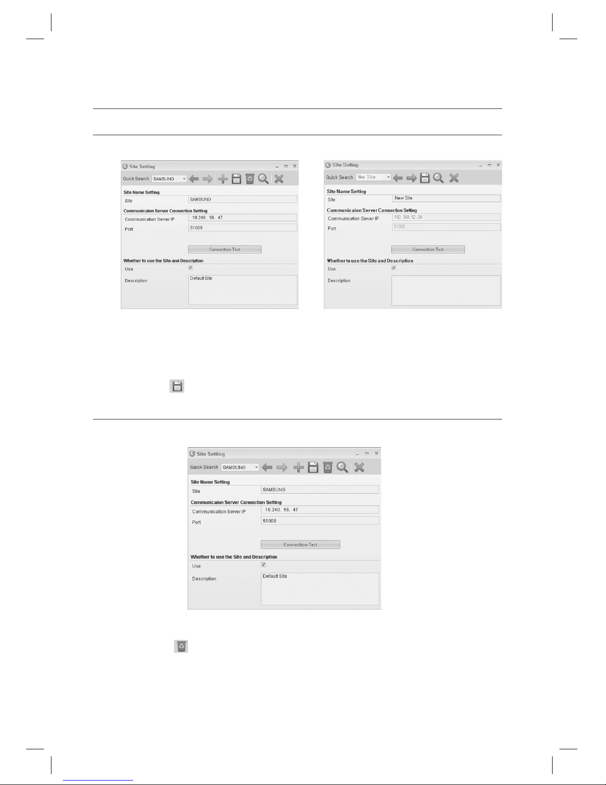
Select an item to change using [Quick Search] in the tool bar.
Make changes as necessary.
In SAMS Pro Lite, you can not change the [Communication Server Connection Setting].
Click Save < > in the tool bar.
SITE SETTING [DELETE]
(This is not available in SAMS Pro Lite.)
Select an item to delete using [Quick Search] in the tool bar.
Click Delete <
> in the tool bar.
When you are prompted to delete the item, click [Yes].
When a site is deleted, all data dependent to the deleted site (including loop, device, door, input, and output
information) are deleted accordingly. Site Setting of SAMS Communication Server Pro should be done again.
1.
2.
J
3.
1.
2.
3.
J
< SAMS Pro > < SAMS Pro Lite >
Page 67
English Englis_ English _67
SYSTEM MANAGEMENT
SITE SETTING [SEARCH]
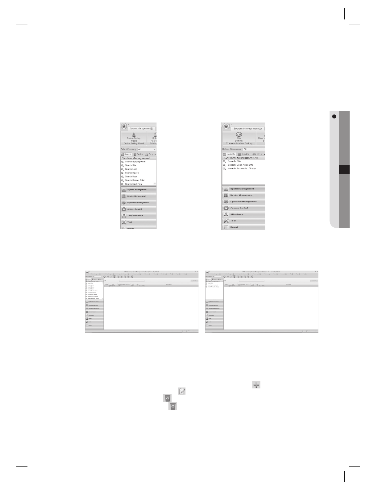
In the left [Search] tab of the main screen, select [System Management] > [Search Site].
The site search result will be displayed in the right pane of the screen.
Provide the search criteria according to the item to fi nd.
Click Search to start searching.
In the search list, you can also add, edit or delete items. From the tool bar, click < > to move to the input
screen. Select a searched item and click < > to move to the edit (change) screen.
Select a searched item and click <
> to delete it. If you want to delete multiple items at once, check all the items
to delete in the search list and click < > to delete them all at once.
1.
2.
3.
4.
J
< SAMS Pro > < SAMS Pro Lite >
< SAMS Pro > < SAMS Pro Lite >
Page 68
68_ system management
system management
LOOP SETTING [ADD – SERIAL COMMUNICATION]
(This is not available in SAMS Pro Lite.)
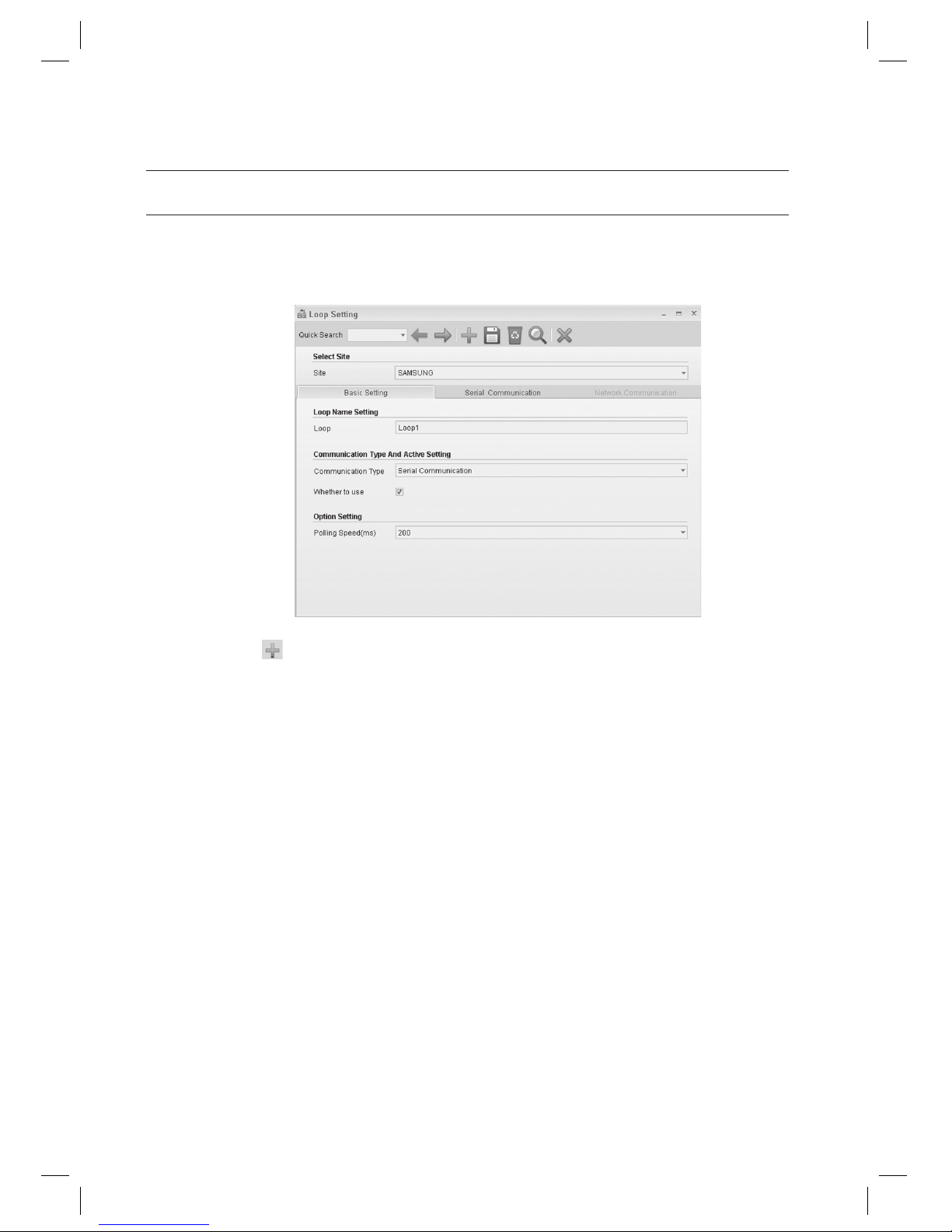
From the upper menu, select [System Management] > [Loop Setting].
Click Add <
> in the tool bar.
Select a [Site].
Enter the [Loop].
Select a [Communication Type]. Select either one of [Serial Communication] or [Network Communication].
Select the [Serial Communication] in this step.
Select [Serial Communication] if communication between the device and SAMS Pro is serial. Select [Network
Communication] for networks such as LAN connections.
Check [Whether to use]. If unchecked, devices connected to the selected loop will not communicate.
Set the interval of polling in [Polling Speed (ms)]. It is recommended to set to 200 ms even the optimal polling
speed may vary depending on devices.
Access controllers will communicate with the management program for data transfer in polling method. Polling
speed means the interval between data requesting polls of the SAMS Communication Server Pro to devices.
Move to the [Serial Communication] tab.
1.
2.
3.
4.
5.
J
6.
7.
J
8.
Page 69
English Englis_ English _69
SYSTEM MANAGEMENT
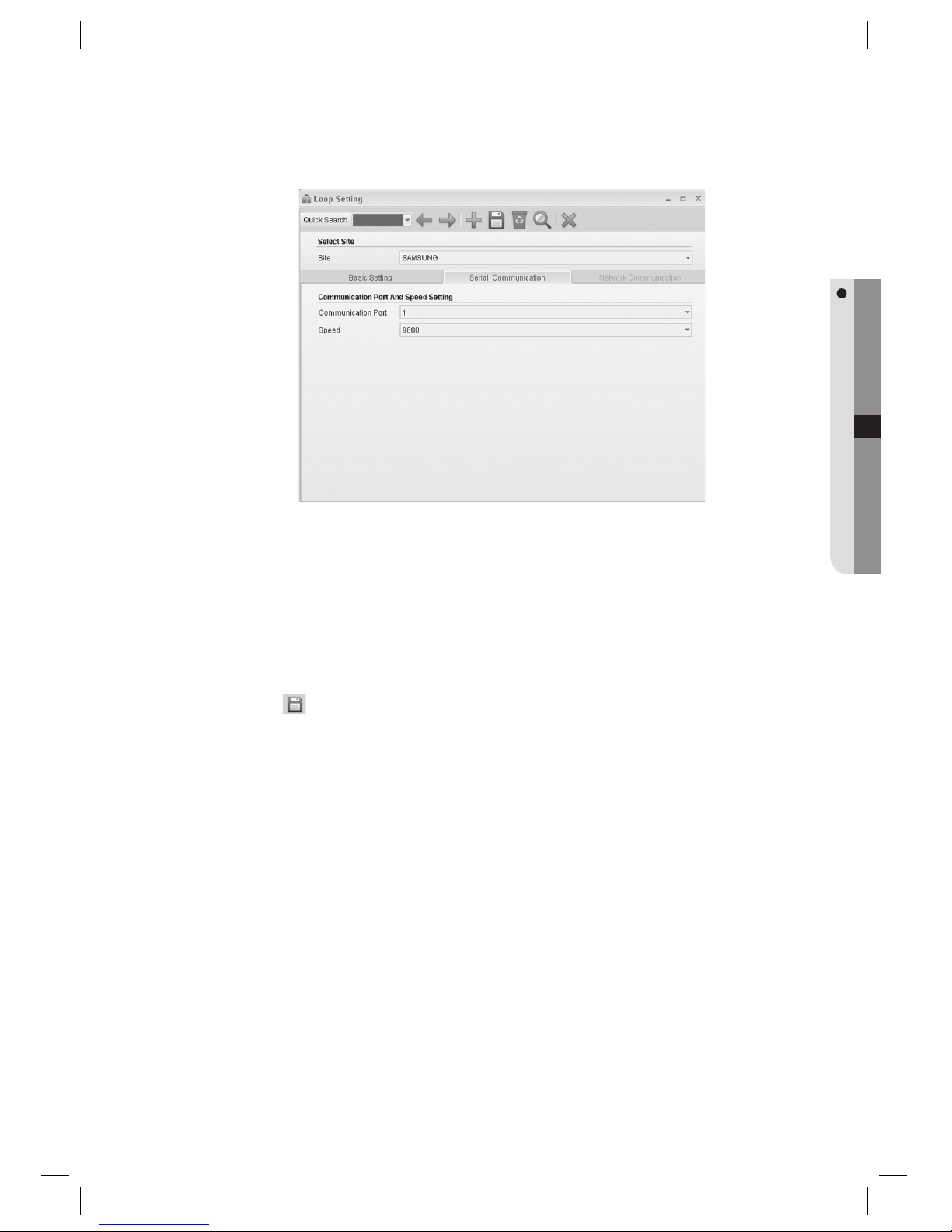
Set the [Communication Port].
Set the [Speed] for the communication.
Communication speed, which is the baud rate, may differ from devices. You can specify the communication speed
for each device (access controller). When setting the communication speed, specifi ed both for the device and
management program must match. For setting the device’s communication setting, refer to the product
documentation for further details.
Click Save < > in the tool bar.
When “Do you want to restart the communication server?” message appears, click [Yes(Y)].
If SAMS Communication Server Pro is running and site confi guration is properly done, communication server will
restart normally. If SAMS Communication Server Pro is not running or the site information is improperly confi gured,
communication server may fail to restart.
9.
10.
J
11.
12.
J
Page 70
70_ system management
system management
LOOP SETTING [ADD – NETWORK COMMUNICATION]
(This is not available in SAMS Pro Lite.)
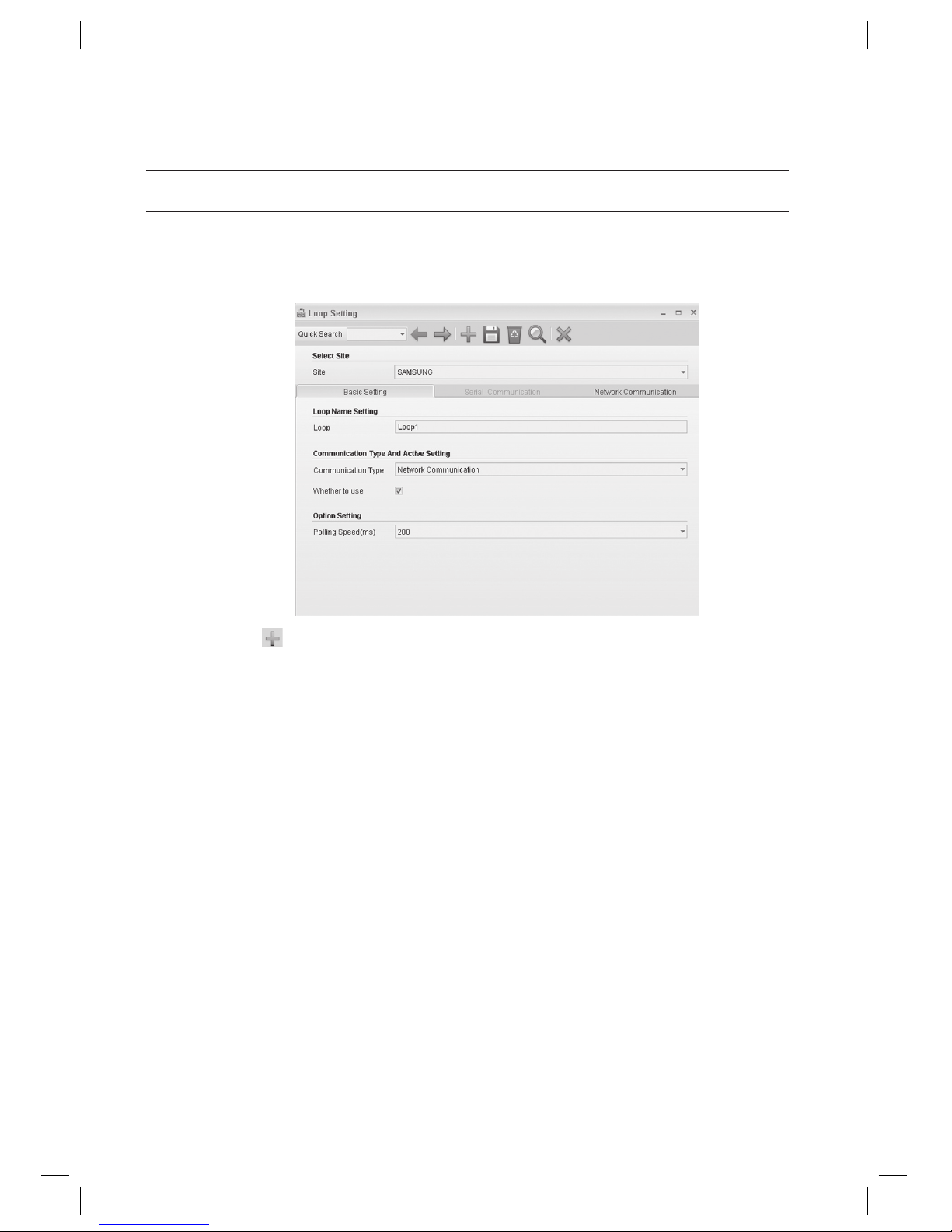
From the upper menu, select [System Management] > [Loop Setting].
Click Add <
> in the tool bar.
Select a [Site].
Enter the [Loop].
Select a [Communication Type]. Select either one of [Serial Communication] or [Network Communication].
Select the [Network Communication] in this step.
Select [Serial Communication] if communication between the device and SAMS Pro is serial.
Select [Network Communication] for networks such as LAN connections.
Select whether to use or not in [Whether to use]. If unchecked, devices connected to the selected loop will not
communicate.
Set the interval of polling in [Polling Speed (ms)]. It is recommended to set to 200 ms even the optimal polling
speed may vary depending on devices.
Access controllers will communicate with the management program for data transfer in polling method. Polling
speed means the interval between data requesting polls of the SAMS Communication Server Pro to devices.
Move to the [Network Communication] tab.
1.
2.
3.
4.
5.
J
6.
7.
J
8.
Page 71
English Englis_ English _71
SYSTEM MANAGEMENT
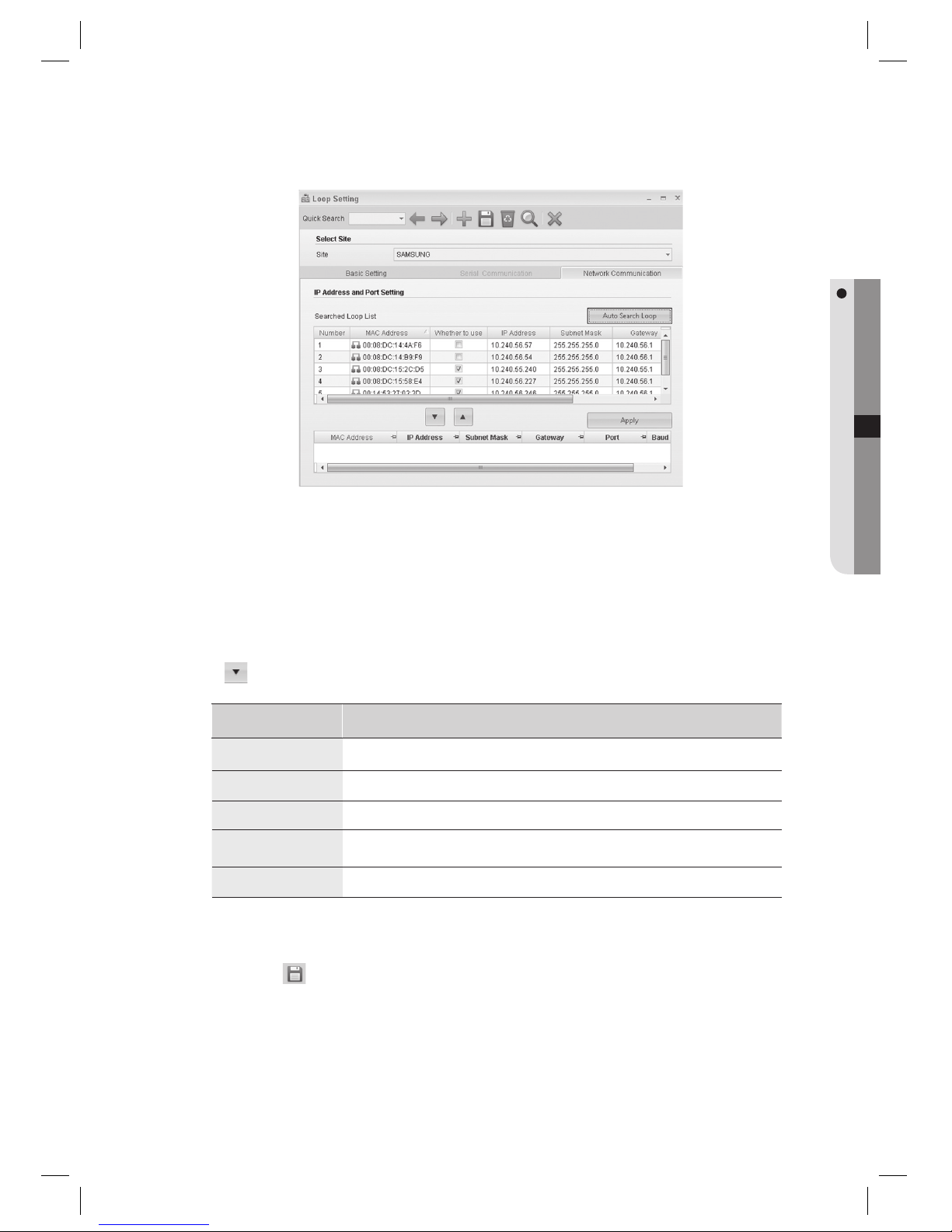
Click [Auto Search Loop].
Searches and displays all devices found in the local network.. Devices already added are indicated as checked in the
Whether to use column. If the operating system is Windows Vista, Auto Search Loop function requires disabling the
Windows Firewall.
(Select the [Exception] tab in [Control Panel] > [Security Center] > [Windows Firewall]. Click [Add Programs] to install
SAMS Pro.)
Select a device to be added to the loop from the search result and use the down arrow key
<
> to move to the bottom. Edit the network properties for the added device, such as IP address, subnet
mask, gateway, port number and baud rate.
Column Name Descriptions
IP addres
Enter the IP address of the added device.
Subnet Mask
Enter the Subnet Mask of the added device.
Gateway
Enter the Gateway address of the added device.
Port
Enter the port number for the communication with the added device. It is recommended to use the default 5000.
Baud Rate
Enter the baud rate of the network converter, which means communication speed.
Click [Apply] to apply the changes.
Click Save <
> in the tool bar.
When “Do you want to restart the communication server?” message appears, click [Yes(Y)].
If SAMS Communication Server Pro is running and site confi guration is properly done, communication server will
restart normally. If SAMS Communication Server Pro is not running or the site information is improperly confi gured,
communication server may fail to restart.
9.
J
10.
11.
12.
13.
J
Page 72
72_ system management
system management
LOOP SETTING [EDIT]
(This is not available in SAMS Pro Lite.)
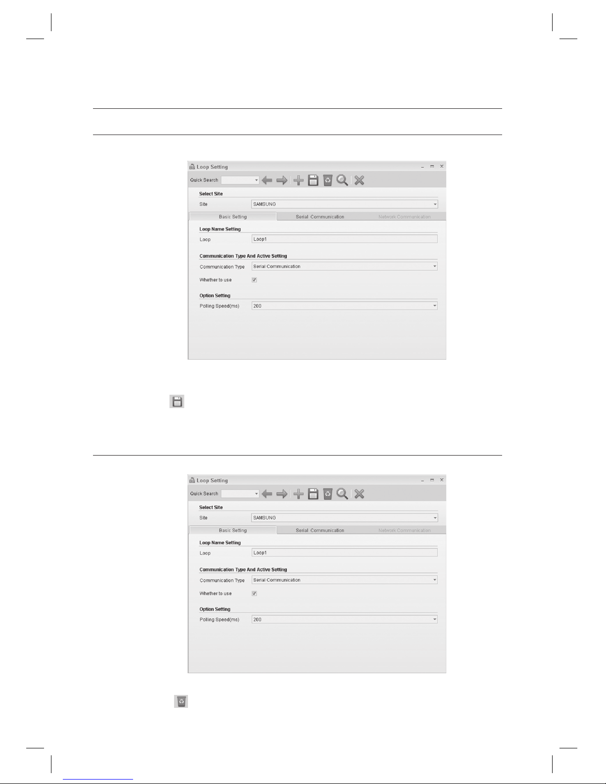
Select an item to change using [Quick Search] in the tool bar.
Make changes as necessary.
Click Save <
> in the tool bar.
When a message of “Do you want to restart the communication server?” appears, Click [Yes(Y)].
LOOP SETTING [DELETE]
(This is not available in SAMS Pro Lite.)
Select an item to delete using [Quick Search] in the tool bar.
Click Delete <
> in the tool bar.
1.
2.
3.
4.
1.
2.
Page 73
English Englis_ English _73
SYSTEM MANAGEMENT
When you are prompted to delete the item, click [Yes].
When a message of “Do you want to restart the communication server?” appears, Click [Yes(Y)].
When a loop is deleted, all data dependent to the deleted loop (including device, door, input, output information) are
deleted accordingly.
LOOP SETTING [SEARCH]
(This is not available in SAMS Pro Lite.)
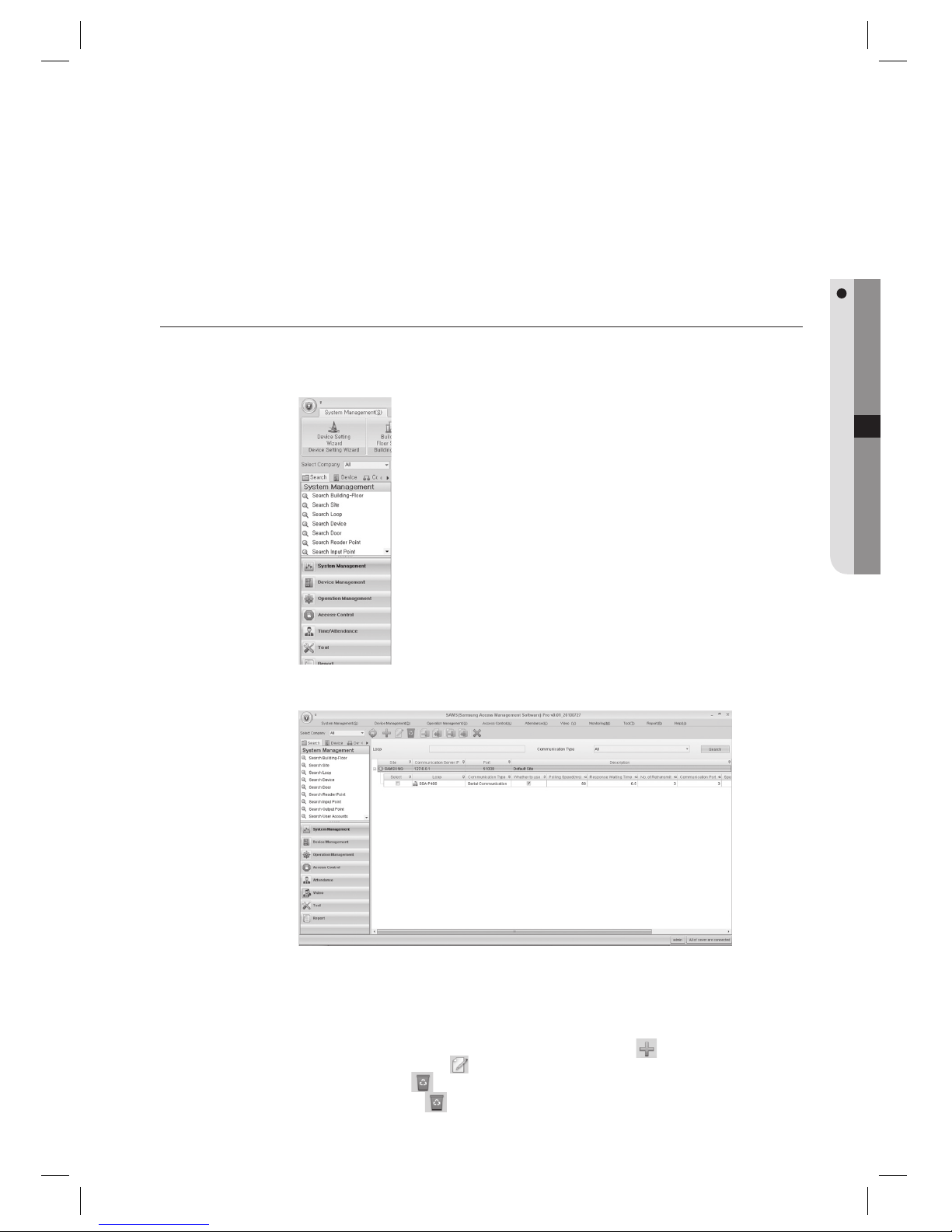
In the left [Search] tab of the main screen, select [System Management] > [Search Loop].
The loop search result will be displayed in the right pane of the screen.
Provide the search criteria according to the item to fi nd.
Click Search to start searching.
In the search list, you can also add, edit or delete items. From the tool bar, click < > to move to the input
screen. Select a searched item and click < > to move to the edit (change) screen.
Select a searched item and click <
> to delete it. If you want to delete multiple items at once, check all the items
to delete in the search list and click <
> to delete them all at once.
3.
4.
J
1.
2.
3.
4.
J
Page 74
74_ system management
system management
DEVICE SETTING [ADD]
(This is not available in SAMS Pro Lite.)
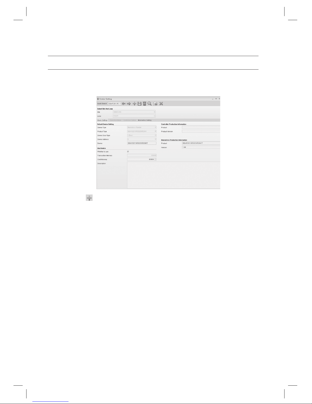
From the upper menu, select [System Management] > [Device Setting].
Click Add <
> in the tool bar.
Select a [Site].
Select a [Loop].
Move to the [Basic Setting] tab.
Select a [Device Type]. Select [Controller] for access controller device, or select [Biometrics Reader] for
biometrics/fi ngerprint readers.
SSA-P102, SSA-P40x, SSA-S21xx, SSA-S30xx series products are controllers, and SSA-R20xx series products are
biometrics readers.
Select the product type for the device to be confi gured in [Product Type].
Select [Device Door Type]. Door Type varies depending on the devices.
SSA-P102, SSA-S21xx, SSA-S30xx series products are 1-door type. SSA-P40x series products are 2~4 Door type.
1.
2.
3.
4.
5.
6.
J
7.
8.
J
Page 75
English Englis_ English _75
SYSTEM MANAGEMENT
Select the [Device Address]. Each controller has its own address for communication. Within the same loop,
devices must have different address. Devices in different loops may have the same address.
Setting the communication address differs from product to product. For setting the device’s communication address,
refer to the product documentation for further details. Note that communication addresses confi gured in SAMS Pro
and corresponding device must match for proper communication between them.
Enter the [Device]. Make sure to name a device not to duplicate already existing device name even for devices
in different loops.
Check [Whether to use]. If unchecked, the selected device will not be activated.
Set the [Card Memory].
Card memory fi eld will be activated or deactivated according to the device type. When this option is enabled, you can
set the card memory for registering to the device and its transaction memory will be automatically defi ned according
to the confi gured card memory.
- Card Memory: Number of registered IDs
- Transaction Memory: Number of contained events
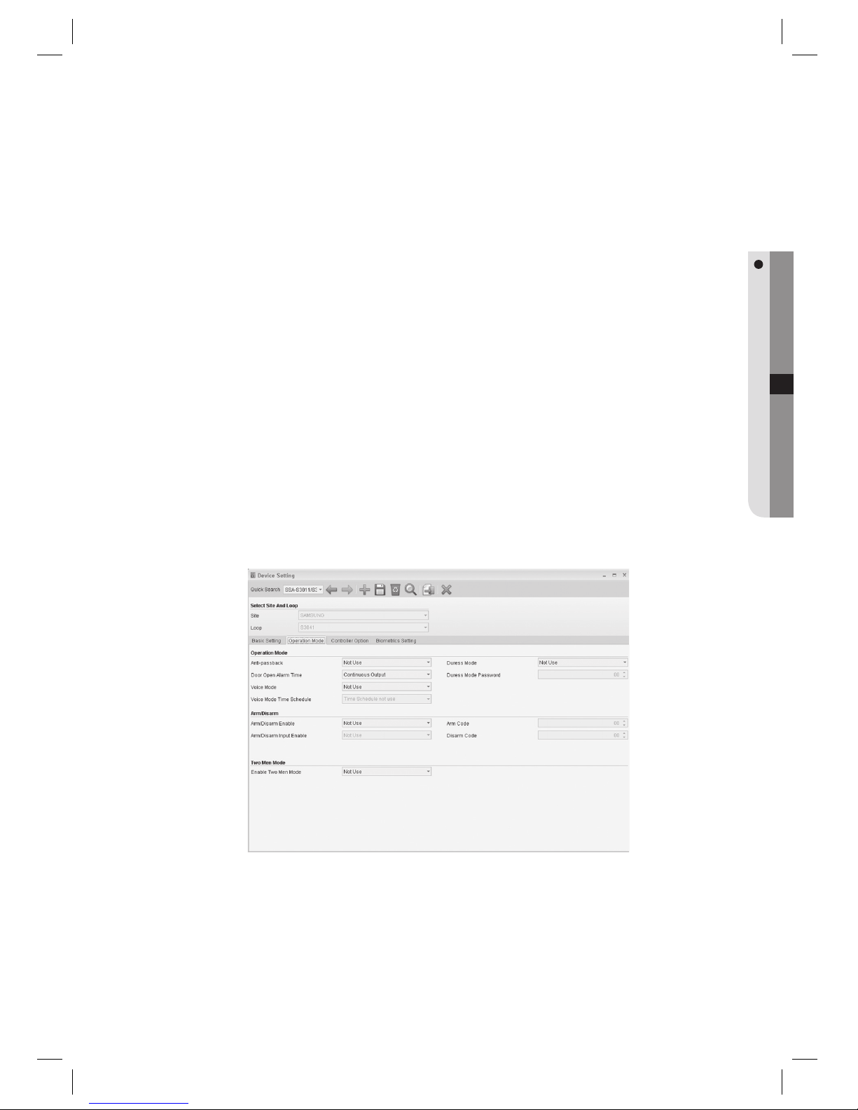
Move to the [Operation Mode] tab.
Items in the Operation Mode tab are enabled or disabled depending on whether the corresponding function is
supported by the device. These optional items require confi gurations only when necessary.
9.
J
10.
11.
12.
J
13.
J
Page 76
76_ system management
system management
Function Name Descriptions
Anti-passback
Antipassback limits door access only when entering and exiting matches if a door is installed with two
separate readers both for entering and exiting respectively. In general, this function is used for preventing
entering a door by following the previous authorization.
Door Open Alarm Time
You can set the delay time until the product triggers the door open alarm if the door stays open after the
Door Relay time. This function requires Door Contact Sensors installed.
Voice mode
You can set to play recorded voice guide.
Voice Mode Time Schedule
You can set time schedule for voice mode, which will play recorded voice guide only within the specifi ed
time table.
Duress Mode
Duress mode requires the Duress Mode Password for enabling this function. Duress mode is a special
feature that outputs a special tacit alarm signal when it is forced to open the restricted area, by entering
2-digit code before authorizing. The door opens as normally but the program generates duress event
which will trigger the alert.
Duress Mode Password
The 2-digit password to trigger the Duress mode.
Arm/Disarm
Alarm controllers of other manufacturers can be connected through the access controller’s output if
required. At the moment, if armed with the ARM code and ARM card, it can be confi gured to make all
access controllers of doors to deny any access requests.
Arm/Disarm Input Enable
If you intend to use the Arm function, you can set the Arm function via a specifi c input point instead of
using the card.
Arm Code
This is a two-digit code required to set the arm function.
Disarm Code
This is a two-digit code required to release the arm function.
Enable Two Men Mode
Enable this when two men operation mode (for administrator and visitor) is required. With the two men
operation mode activated, the door will be opened if both administrator and visitor card issued in card
holder management are entered in a row.
Duress mode and Arm/Disarm will require keypad readers (SSA-R2000, SSA-R2001, etc.) if used with the
SSA-P102 and 400 series products.
Move to the [Controller Option] tab.
J
14.
Page 77
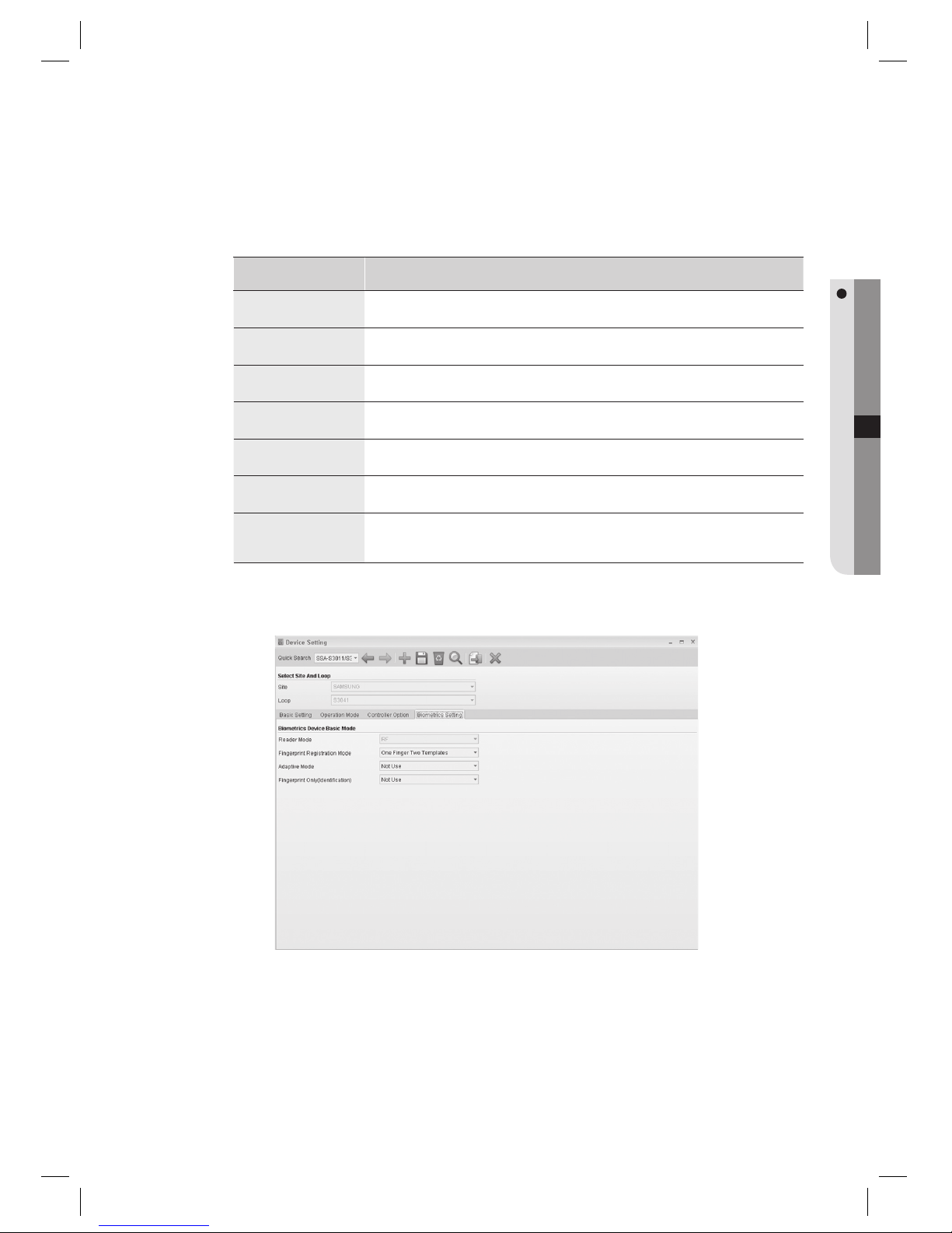
English Englis_ English _77
SYSTEM MANAGEMENT
Items in the Controller Option tab are enabled or disabled depending on whether the corresponding function is
supported by the device. These optional items require confi gurations only when necessary.
Function Name Descriptions
LCD Display
Select whether to display the access control result and the card number on the monitor.
Output Operation Time
Unit(sec)
Set the output operation time interval for the controller in seconds, such as 1 sec and 0.1 sec.
Whether to enable keypad
For devices with built-in keypad, select whether to allow keypad use.
Wiegand Output
Select whether to output the authorization number through the Wiegand output on a successful accessing.
Duplicated Event Checking
Select whether to detect duplicated events.
User Name Display
Specify whether to display accessing user’s name. (Available only for LX series)
Output Time Schedule
Mode
Sets the operation mode of the device’s output time schedule. When selected time schedule alone, output
will be generated on scheduled time. When selected time schedule + card, output will be generated only
after the fi rst authorization from the scheduled time.
Move to the [Biometrics Setting] tab.
J
15.
Page 78
78_ system management
system management
Items in the Biometrics Setting tab are enabled or disabled depending on whether the corresponding function is
supported by the device. These optional items require confi gurations only when necessary.
Function Name Descriptions
Reader Mode
You can select operation mode of biometrics readers.
RF Only
When the card is presented to the reader, the device reads and transfers the card number to the
controller and the controller decides whether to grant accessing according to the registered information.
RF + Fingerprint
Access authorization requires both the card and fi ngerprint.
If the fi ngerprint scanner does not turn on red indicator even when the card is identifi ed, the user has
no registered fi ngerprint. When the fi ngerprint authorization is successful, the device transfers the
card number to the controller and the controller decides whether to grant accessing according to the
registered information.
Fingerprint Registration
Mode
Sets the Fingerprint Registration mode. You can select from One Finger Two Templates and Two Fingers
Two Templates options.
One Finger Two Templates
Registration mode that requires two templates of the same fi ngerprint. This mode improves the
fi ngerprint recognition rate.
Two Fingers Two Templates
Registration mode that requires one template for each fi ngerprint of two different fi ngers.
Recognition rate of this mode is slightly lower than that of one fi nger mode, this mode enables
authorization using another fi ngerprint when the other fi ngerprint is damaged (by wound or
contamination).
Note that transmitting fi ngerprint information acquired by Two Fingers Two Templates mode to a
device confi gured with One Finger Two Templates will cause errors in data transfer or access
authorization.
J
Adaptive Mode
You can select adaptive mode for the latent fi ngerprint compensation. In general, the latent fi ngerprint
compensation is called Adaptive function, and it improves the recognition rate. Instead, the recognition
speed is slightly slowed down.
This function improves the recognition rate by compensating dry and wet fi ngerprints. When it is enabled,
the fi ngerprint scanner’s red indicator will blink during the recognition. Set this function not to use if
increased recognition speed is necessary. When it is disabled, the fi ngerprint scanner’s red indicator will
turn on during the recognition.
Fingerprint Only
(Identifi cation)
IDENTIFICATION Mode: Select one from “Use” and “Not Use”, whether to authorize only with the
fi ngerprint identifi cation.
Click Save < > in the tool bar.
When “Do you want to restart the communication server?” message appears, click [Yes(Y)].
If SAMS Communication Server Pro is running and site confi guration is properly done, communication server will
restart normally. If SAMS Communication Server Pro is not running or the site information is improperly confi gured,
communication server may fail to restart.
Click Transmit button < > in the toolbar to send the confi guration to the device.
To confi rm the data transmission and its result, run the [Monitoring] > [Integrated Monitoring] from the toolbar
before clicking the transmit button. The data transmission result of each item will be displayed in the [Auditing Log]
window of the integrated monitoring screen.
J
16.
17.
J
18.
J
Page 79
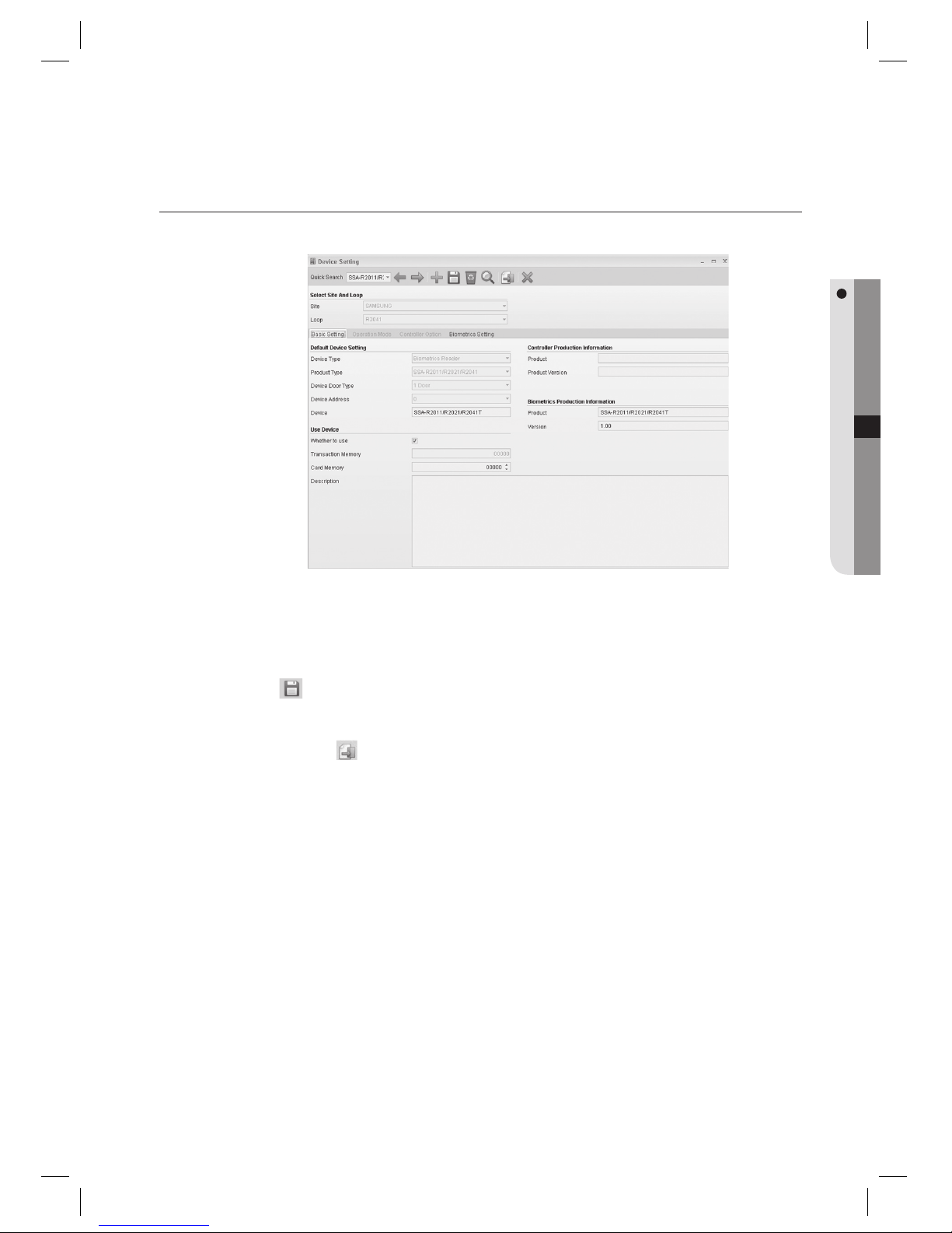
English Englis_ English _79
SYSTEM MANAGEMENT
DEVICE SETTING [EDIT]
(This is not available in SAMS Pro Lite.)
Select an item to change using [Quick Search] in the tool bar.
Make changes as necessary.
Click Save <
> in the tool bar. (When a message of “Do you want to restart the communication server?”
appears, Click [Yes(Y)].)
Click Transmit button <
> in the tool bar.
To confi rm the data transmission and its result, run the [Monitoring] > [Integrated Monitoring] from the toolbar
before clicking the transmit button. The data transmission result of each item will be displayed in the [Auditing Log]
window of the integrated monitoring screen.
1.
2.
3.
4.
J
Page 80
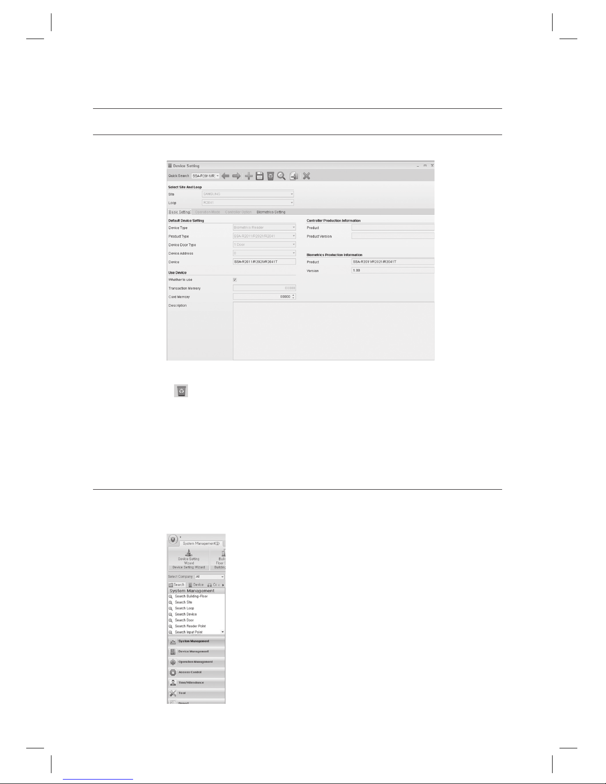
80_ system management
system management
DEVICE SETTING [DELETE]
(This is not available in SAMS Pro Lite.)
Select an item to delete using [Quick Search] in the tool bar.
Click Delete <
> in the tool bar.
When you are prompted to delete the item, click [Yes]. (When a message of “Do you want to restart the
communication server?” appears, Click [Yes(Y)].)
When a device is deleted, all data dependent to the deleted device (including door, input, output information) are
deleted accordingly.
DEVICE SETTING [SEARCH]
(This is not available in SAMS Pro Lite.)
In the left [Search] tab of the main screen, select [System Management] > [Search Device].
1.
2.
3.
J
1.
Page 81
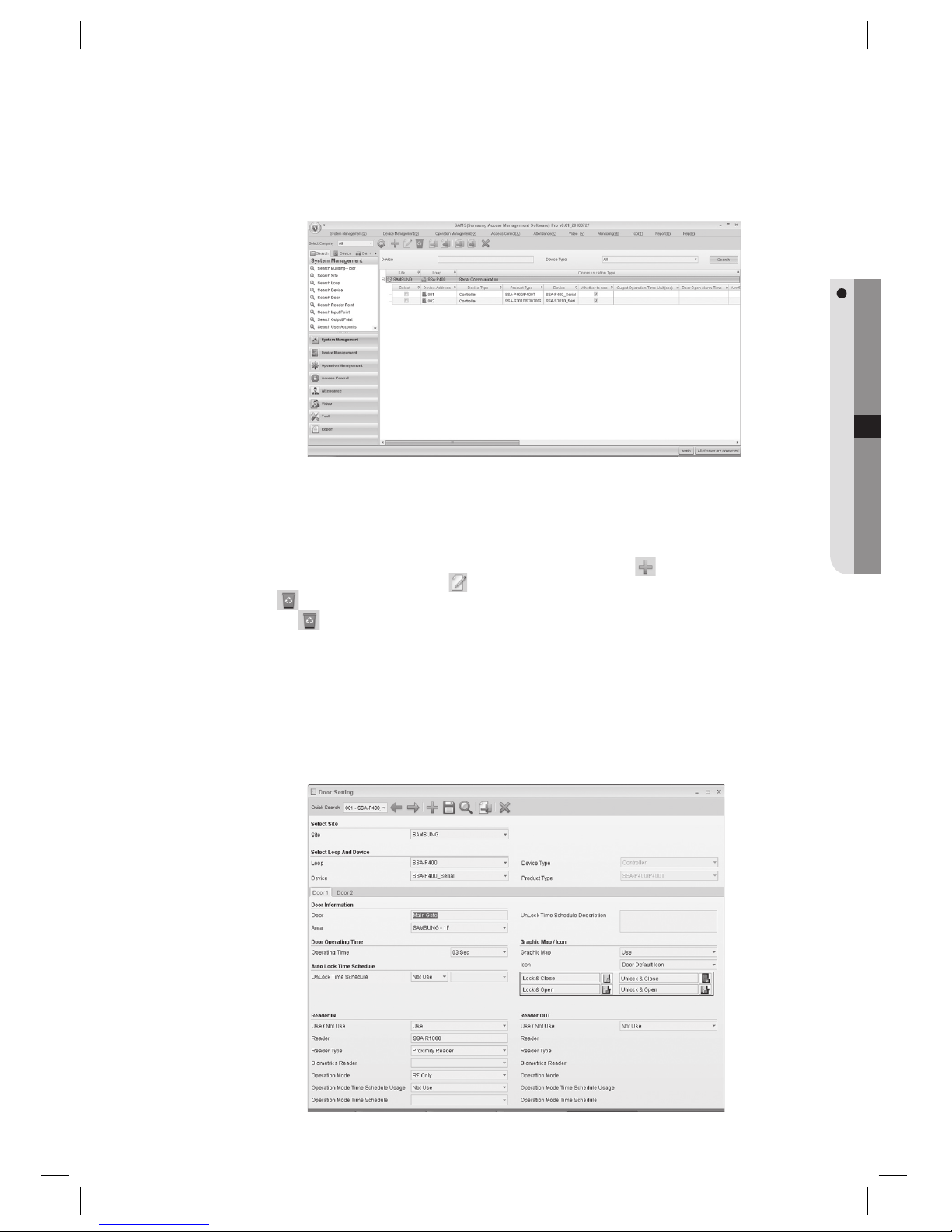
English Englis_ English _81
SYSTEM MANAGEMENT
In the right pane of the main screen, the Device search screen appears.
Provide the search criteria according to the item to fi nd.
Click Search to start searching.
In the search list, you can also add, edit or delete items. From the tool bar, click < > to move to the input
screen. Select a searched item and click < > to move to the edit (change) screen. Select a searched item and
click <
> to delete it. If you want to delete multiple items at once, check all the items to delete in the search list
and click <
> to delete them all at once.
DOOR SETTING [ADD]
(This is not available in SAMS Pro Lite.)
From the upper menu, select [System Management] > [Door Setting].
2.
3.
4.
J
1.
Page 82

82_ system management
system management
Click Add < > in the tool bar.
Select a [Site].
Select a [Loop]. Select the Device.
Move to the [Door 1] tab. According to the selected device’s type, number of door tabs may vary.
When selected a 4-Door device, there will be 4 door setting tabs appeared.
Enter the [Door].
Select [Area].
Select a [Operating Time]. This fi eld is an optional item, set this if required. Set the unlock duration time on a
successful authorization by the access control.
Sample screen shows the case of SSA-P40x(T), when Door Lock is installed on the Relay 1. If the Door Lock is
not connected to the Relay 1, leave it empty and set the time in the corresponding relay in [System Management]
-> [Reader Point Setting].
Select a [Auto Lock Time Schedule]. This fi eld is an optional item, set this if required. Use this option to set the
door to be opened or locked for the confi gured time schedule synchronized with the time schedule setting.
Select a [Graphic Map / Icon]. This fi eld is an optional item, set this if required. Use this when you assign icons
for doors on a graphic map.
Select an [Icon]. This fi eld is an optional item, set this if required. Sets the icon for the door.
Set [Reader IN] and [Reader OUT]. If reader device is installed only for entering, set [Reader IN] only. Set
whether to use or not for each reader in [Use / Not Use] fi eld.
Enter the [Reader].
Select a [Reader Type].
For SSA-R1xxx series, select Proximity Reader. For SSA-S21xx and SSA-S30xx series products too, select Proximity
Reader since these Standalone controllers have built-in proximity readers. For SSA-R2000/2001, select Proximity
Reader+Keypad. For SSA-R2010/R2020/R2040/R2011/R2021/R2041 products, select Biometrics Reader.
Select the [Biometrics Reader]. If the [Reader Type] is set to [Biometrics Reader], select the appropriate
biometrics reader.
2.
3.
4.
5.
6.
7.
8.
9.
10.
11.
12.
13.
14.
J
15.
Page 83
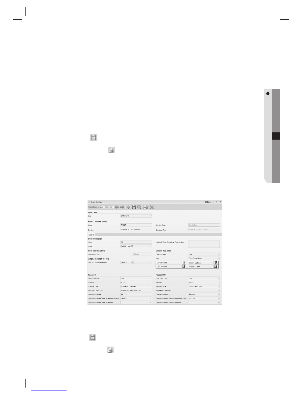
English Englis_ English _83
SYSTEM MANAGEMENT
Select a [Operation Mode]. Operation Mode options differs from the reader types. [RF Only] authorizes access
only with the card. [RF+Fingerprint(Password)] authorizes access with combination of card and fi ngerprint or
card and password. [RF+Fingerprint+Password] authorizes access with combination of card, fi ngerprint and
password.
Select whether to use [Operation Mode Time Schedule Usage]. This fi eld is an optional item, set this if required.
With linked to the time schedule, this function sets the reader’s operation mode to RF Only within the specifi ed
time schedule despite of the mode setting, and sets to the designated operation mode during the time period
other than the scheduled time.
Select the [Operation Mode Time Schedule]. Select the time schedule if the [Operation Mode Time Schedule
Usage] is set to [Use].
Click Save <
> in the tool bar.
Click Transmit button <
> in the toolbar to send the confi guration to the device.
To confi rm the data transmission and its result, run the [Monitoring] > [Integrated Monitoring] from the toolbar
before clicking the transmit button. The data transmission result of each item will be displayed in the [Auditing Log]
window of the integrated monitoring screen.
DOOR SETTING [EDIT]
(This is not available in SAMS Pro Lite.)
Select an item to change using [Quick Search] in the tool bar.
Make changes as necessary.
Click Save <
> in the tool bar.
Click Transmit button <
> in the tool bar.
16.
17.
18.
19.
20.
J
1.
2.
3.
4.
Page 84
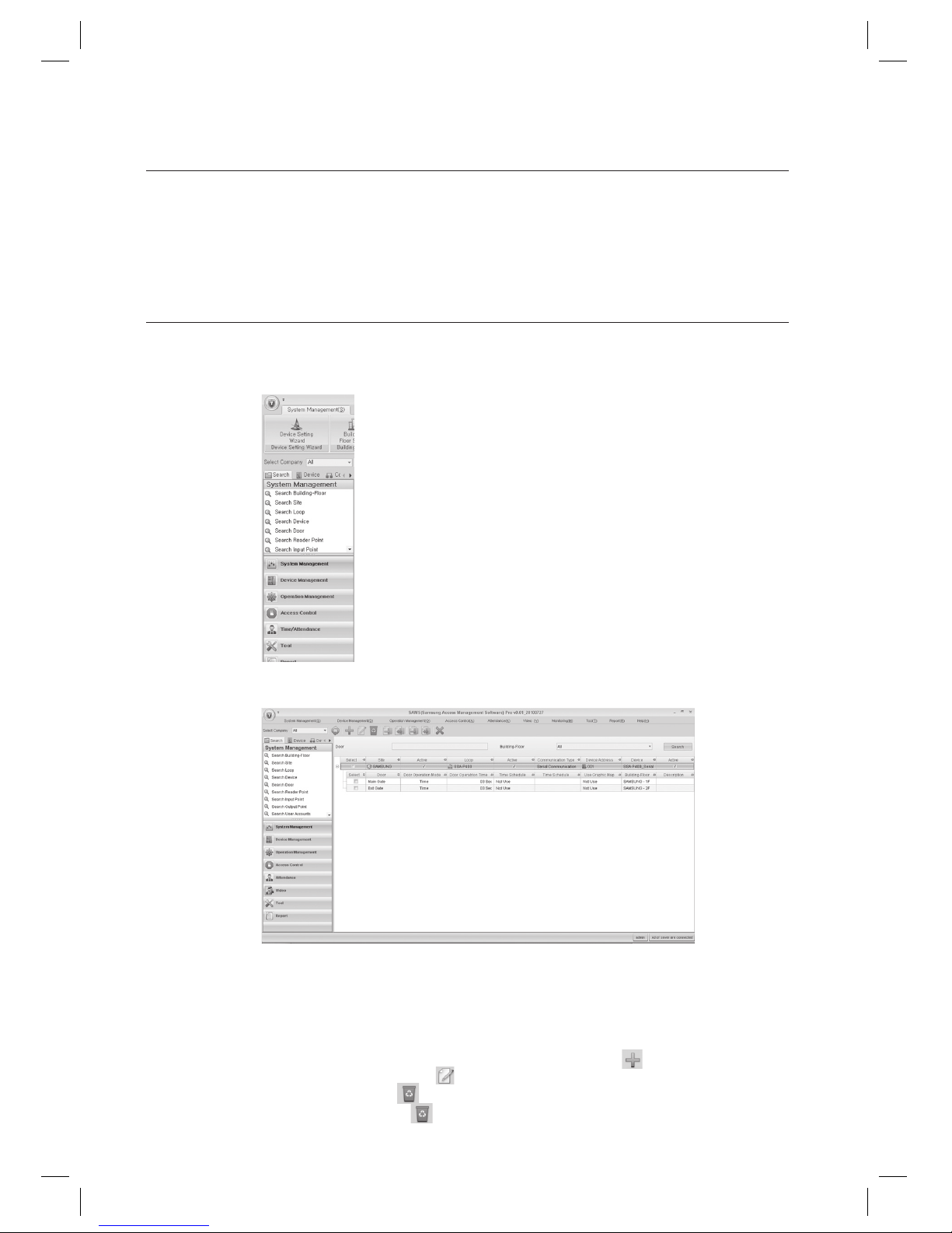
84_ system management
system management
To confi rm the data transmission and its result, run the [Monitoring] > [Integrated Monitoring] from the toolbar
before clicking the transmit button. The data transmission result of each item will be displayed in the [Auditing Log]
window of the integrated monitoring screen.
DOOR SETTING [SEARCH]
(This is not available in SAMS Pro Lite.)
In the left [Search] tab of the main screen, select [System Management] > [Search Door].
In the right pane of the main screen, the Door search screen appears.
Provide the search criteria according to the item to fi nd.
Click Search to start searching.
In the search list, you can also add, edit or delete items. From the tool bar, click < > to move to the input
screen. Select a searched item and click < > to move to the edit (change) screen.
Select a searched item and click < > to delete it. If you want to delete multiple items at once, check all the items
to delete in the search list and click < > to delete them all at once.
J
1.
2.
3.
4.
J
Page 85
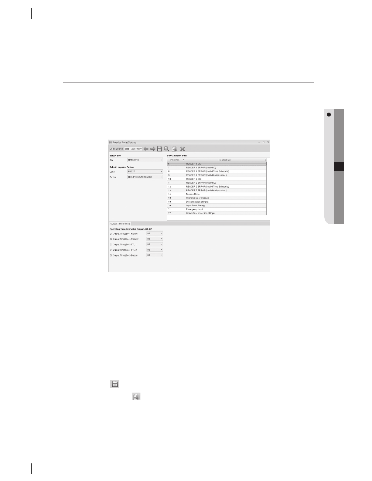
English Englis_ English _85
SYSTEM MANAGEMENT
READER POINT SETTING [EDIT]
(This is not available in SAMS Pro Lite.)
There is no Add and Delete function for Reader Point Setting. Reader points are confi gured automatically at the time of
device setting automatically, provided with default values appropriately for the device operations. Editing the reader point
setting is provided for changes and further refi ning of the settings.
From the upper menu, select [System Management] > [Reader Point Setting].
Select an item to change using [Quick Search] in the tool bar.
Available reader points are listed in the [Select Reader Point] list on the right pane of the screen.
Reader points displayed may differ from device’s type that is registered in the Device Setting.
You can set output signal’s duration for each item listed in the [Select Reader Point]. For example, you can
specify the signal duration for which output for how many seconds long whenever the Reader 1 OK event
occurs on the reader connected to the controller. In general, Output 1 is set to 03 seconds of activation when
the Reader 1 OK event occurs.
Output operation confi guration each reader points may differ from devices. For further details, refer to the controller’s
product documentation.
Select a reader point to be edited from the [Select Reader Point] list, and confi gure the output time settings.
Click Save <
> in the tool bar.
Click Transmit button <
> in the toolbar to send the confi guration to the device.
To confi rm the data transmission and its result, run the [Monitoring] > [Integrated Monitoring] from the toolbar
before clicking the transmit button.
The data transmission result of each item will be displayed in the [Auditing Log] window of the integrated monitoring
screen.
J
1.
2.
3.
J
4.
J
5.
6.
7.
J
Page 86
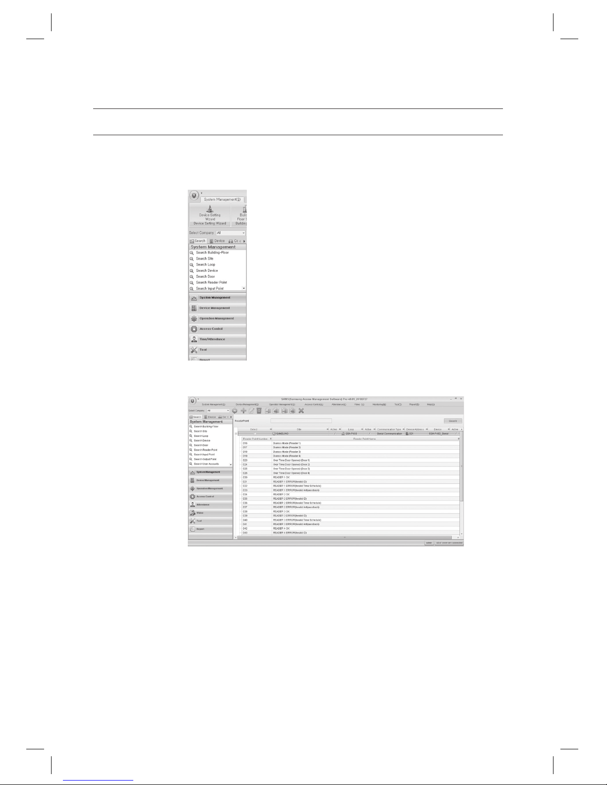
86_ system management
system management
READER POINT SETTING [SEARCH]
(This is not available in SAMS Pro Lite.)
In the left [Search] tab of the main screen, select [System Management] > [Search Reader Point].
In the right pane of the main screen, the Reader Point search screen appears.
Provide the search criteria according to the item to fi nd.
Click Search to start searching.
1.
2.
3.
4.
Page 87
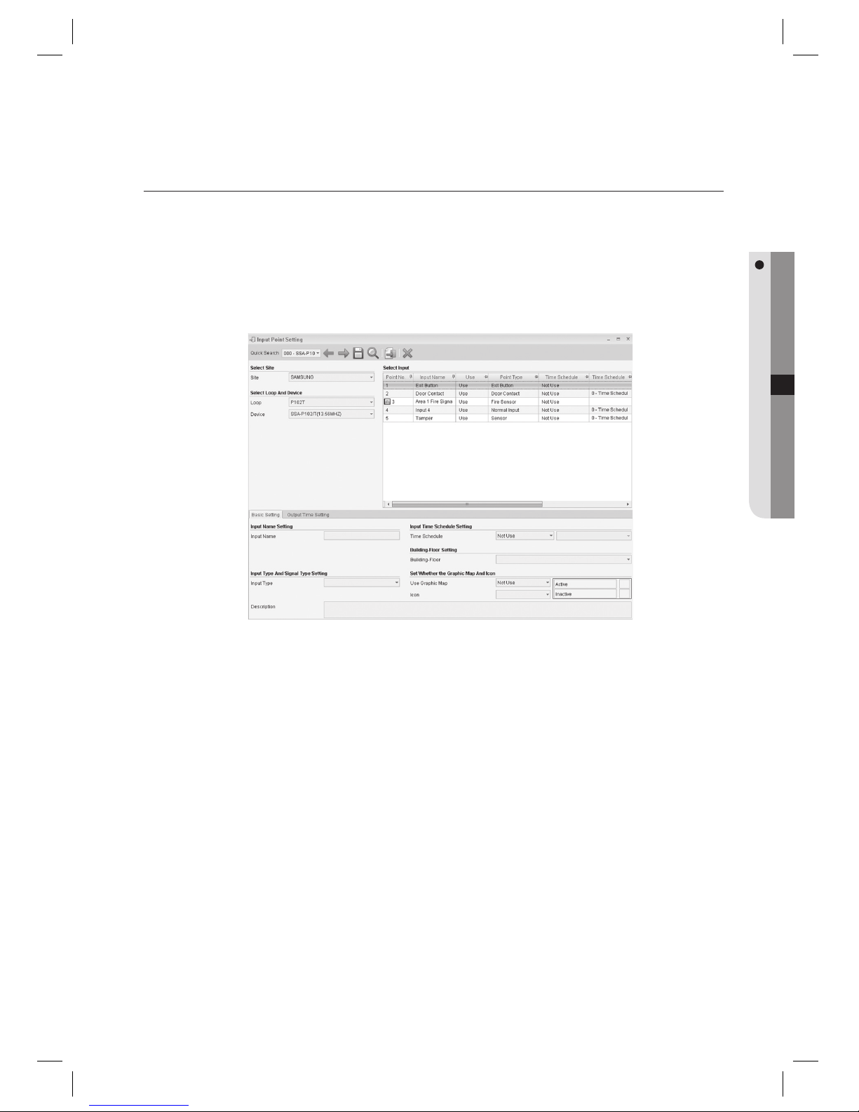
English Englis_ English _87
SYSTEM MANAGEMENT
INPUT POINT SETTING [EDIT]
(This is not available in SAMS Pro Lite.)
There is no Add and Delete function for Input Point Setting. Input points are confi gured automatically at the time of
device setting automatically, provided with default values appropriately for the device operations. Editing the input
point setting is provided for changes and further refi ning of the settings.
From the upper menu, select [System Management] > [Input Point Setting].
Select an item to change using [Quick Search] in the tool bar.
Available input points are listed in the [Select Input] list on the right pane of the screen.
Input points displayed may differ from device’s type that is registered in the Device Setting.
Select an input point to be edited from the [Select Input] list.
Move to the [Basic Setting] tab.
Enter the [Input Name]. The entered name is used for displaying events on the integrated monitoring screen
when an event occurs on the corresponding input point.
Select an [Input Type]. Select [Exit Button] when the input is connected to an exit button, [Sensor] for sensors,
[Door Contact] for door contact sensors, or [Fire Sensor] for fi re detection sensors. For other devices, select
[Normal Input].
Select the [Time Schedule]. This fi eld is an optional item, set this if required. Set the time schedule for each
input, if its function is linked to a time schedule. You can set the input to operate only for the time specifi ed in
the time schedule.
J
1.
2.
3.
J
4.
5.
6.
7.
8.
Page 88

88_ system management
system management
Select a [Building-Floor].
Select whether to use the Graphic Map in [Use Graphic Map]. This fi eld is an optional item, set this if required.
Use this when you assign icons for inputs on a graphic map.
Select an [Icon]. This fi eld is an optional item, set this if required. Sets the icon for the input.
Move to the [Output Time Setting] tab.
You can set output signal’s duration for each input point. For example, pressing the exit button requires
signaling the door contact of the corresponding door to open it. In general, Output 1 is set to 03 seconds of
activation when the exit button is pressed.
Select an input point to be edited from the [Select Input] list, and confi gure the output time settings.
Click Save <
> in the tool bar.
Click Transmit button <
> in the toolbar to send the confi guration to the device.
To confi rm the data transmission and its result, run the [Monitoring] > [Integrated Monitoring] from the toolbar
before clicking the transmit button. The data transmission result of each item will be displayed in the [Auditing Log]
window of the integrated monitoring screen.
INPUT POINT SETTING [SEARCH]
(This is not available in SAMS Pro Lite.)
In the left [Search] tab of the main screen, select [System Management] > [Search Input Point].
9.
10.
11.
12.
13.
14.
15.
16.
J
1.
Page 89
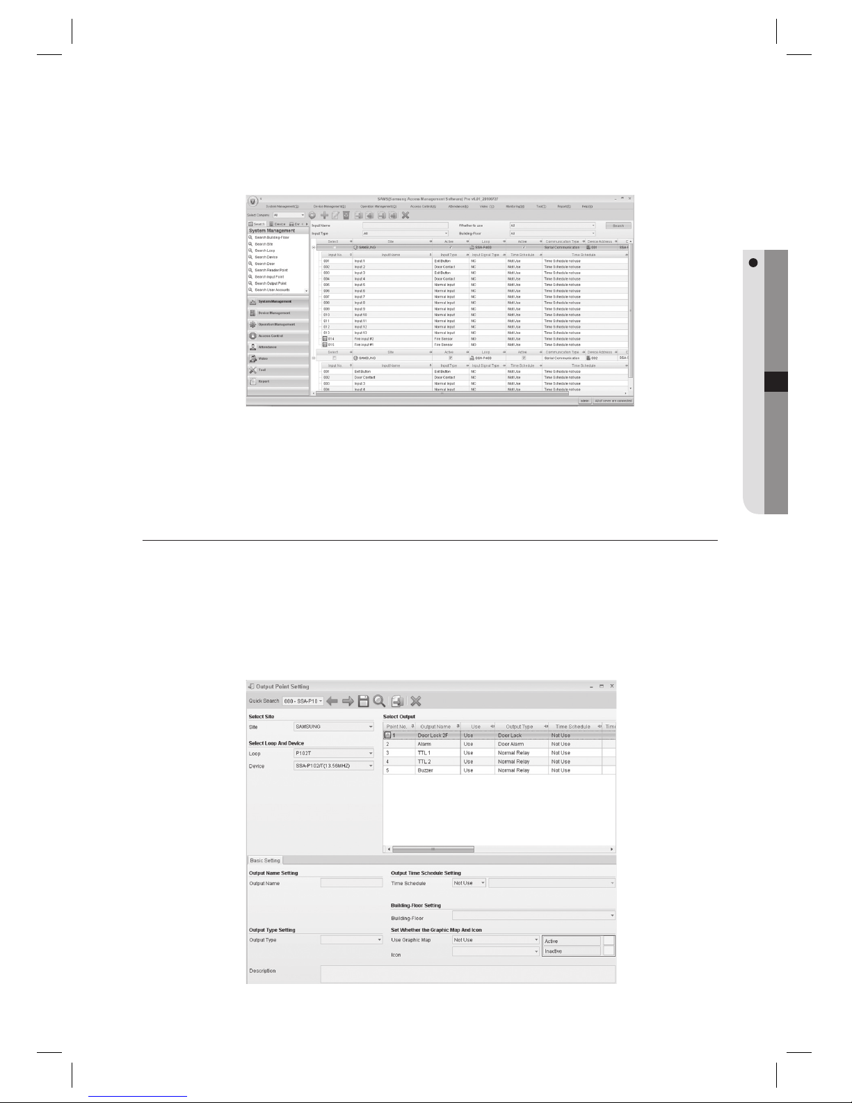
English Englis_ English _89
SYSTEM MANAGEMENT
In the right pane of the main screen, the Input Point search screen appears.
Provide the search criteria according to the item to fi nd.
Click Search to start searching.
OUTPUT POINT SETTING [EDIT]
(This is not available in SAMS Pro Lite.)
There is no Add and Delete function for Output Point Setting. Output points are confi gured automatically at the time
of device setting automatically, provided with default values appropriately for the device operations. Editing the
output point setting is provided for changes and further refi ning of the settings.
From the upper menu, select [System Management] > [Output Point Setting].
2.
3.
4.
J
1.
Page 90

90_ system management
system management
Select an item to change using [Quick Search] in the tool bar.
Available output points are listed in the [Select Output] list on the right pane of the screen.
Output points displayed may differ from device’s type that is registered in the Device Setting.
Select an output point to be edited from the [Select Output] list.
Move to the [Basic Setting] tab.
Enter the [Output Name].
Select an [Output Type]. Select [Door Lock] when the output is connected to a door lock, [Door Alarm] for door
alarm devices, or [General] for other devices.
Select the [Time Schedule]. This fi eld is an optional item, set this if required. Set the time schedule for each
output, if its function is linked to a time schedule. You can set the output to operate only for the time specifi ed in
the time schedule.
Select a [Building-Floor].
Select whether to use the Graphic Map in [Use Graphic Map]. This fi eld is an optional item, set this if required.
Use this when you assign icons for inputs on a graphic map.
Select an [Icon]. This fi eld is an optional item, set this if required. Sets the icon for the input.
Click Save <
> in the tool bar.
Click Transmit button <
> in the toolbar to send the confi guration to the device.
To confi rm the data transmission and its result, run the [Monitoring] > [Integrated Monitoring] from the toolbar
before clicking the transmit button. The data transmission result of each item will be displayed in the [Auditing Log]
window of the integrated monitoring screen.
2.
3.
J
4.
5.
6.
7.
8.
9.
10.
11.
12.
13.
J
Page 91
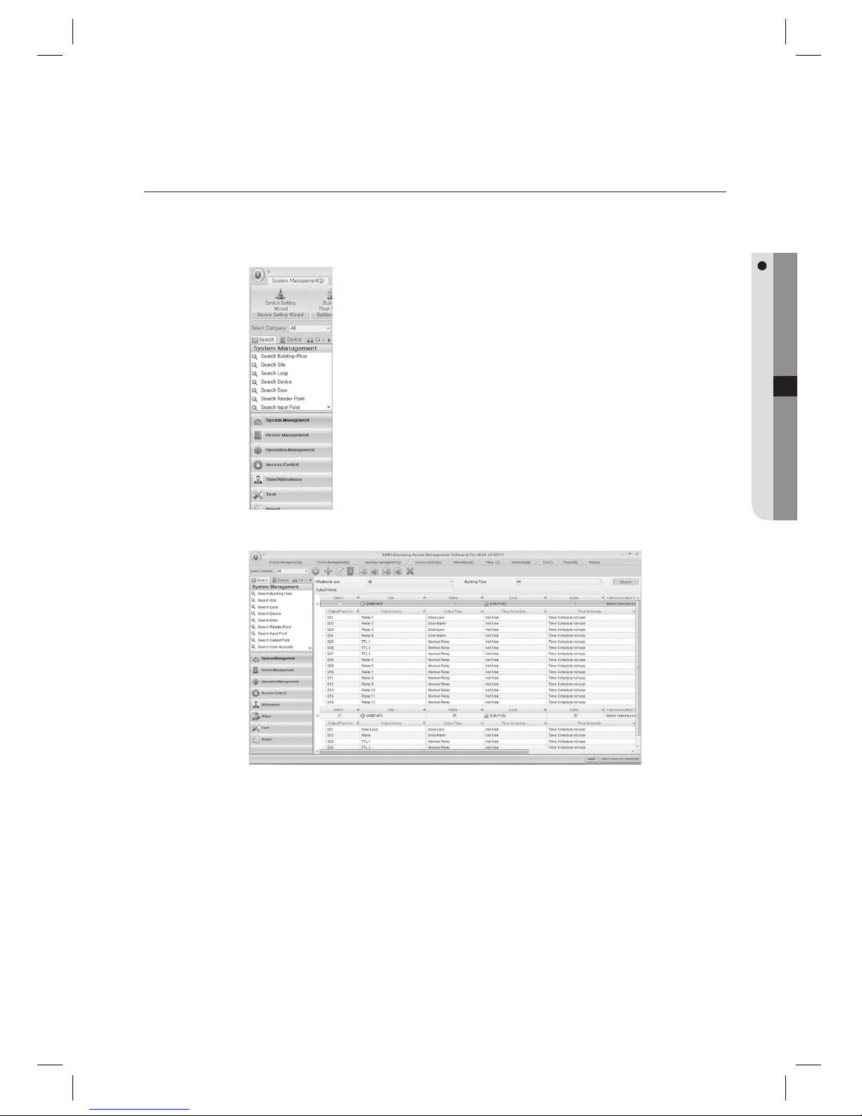
English Englis_ English _91
SYSTEM MANAGEMENT
OUTPUT POINT SETTING [SEARCH]
(This is not available in SAMS Pro Lite.)
In the left [Search] tab of the main screen, select [System Management] > [Search Output Point].
In the right pane of the main screen, the Output Point search screen appears.
Provide the search criteria according to the item to fi nd.
Click Search to start searching.
1.
2.
3.
4.
Page 92
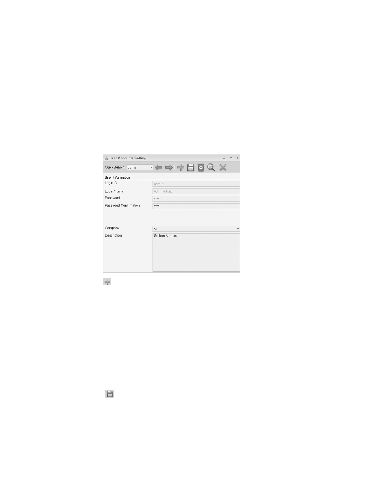
92_ system management
system management
USER ACCOUNTS SETTING [ADD]
Adds user accounts permitted to login to the program.
- Login ID: Enter the user’s login ID. (Required)
- Password: Enter the password of the account. (Required)
- Password Confi rmation: Enter the same password of the account. (Required)
- Company: Select the company to which the user belongs.
- Description: Enter the user’s description.
From the upper menu, select [System Management] > [User Accounts Setting].
Click Add <
> in the tool bar.
Enter the user’s [Login ID].
Enter the [Login Name].
Enter the [Password] and [Password Confi rmation].
Select a [Company].
If selected [All], the account can manage information of all registered companies. If selected a certain company
name registered, the account can manage the selected company information only.
Click Save < > in the tool bar.
1.
2.
3.
4.
5.
6.
J
7.
Page 93
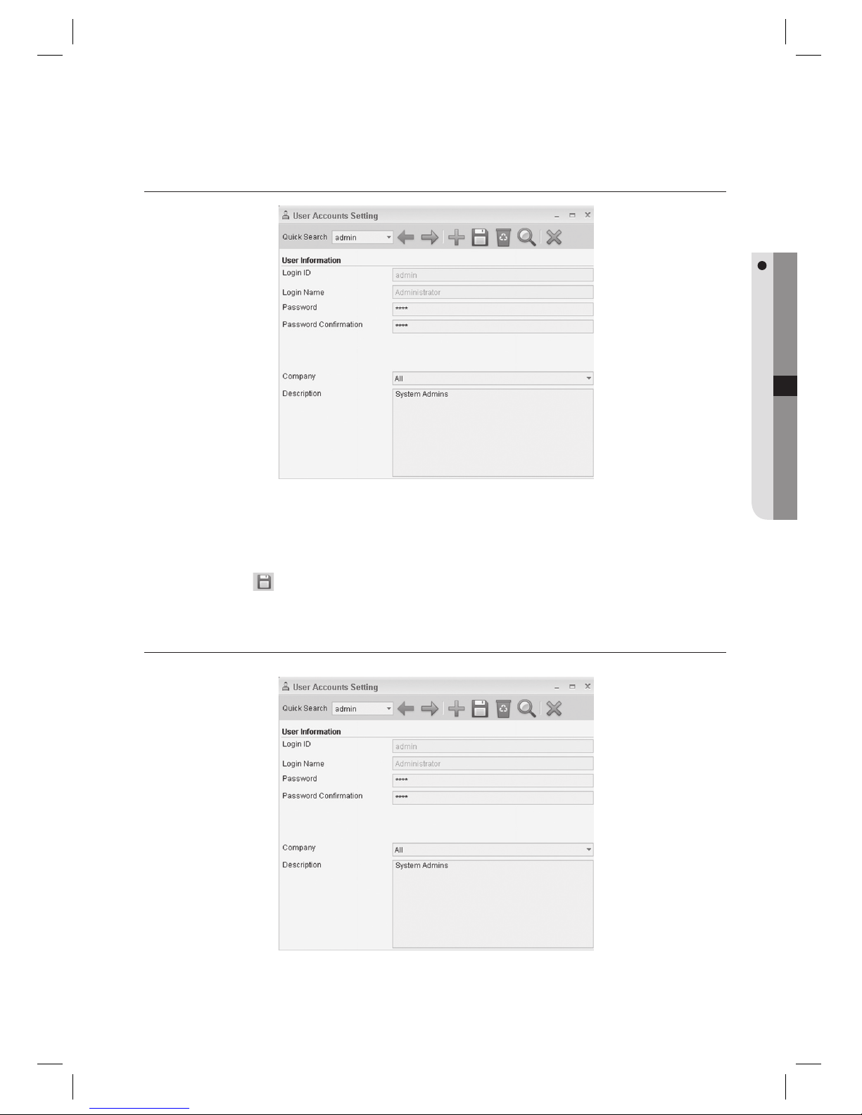
English Englis_ English _93
SYSTEM MANAGEMENT
USER ACCOUNTS SETTING [EDIT]
Select an item to change using [Quick Search] in the tool bar.
Make changes as necessary.
Click Save <
> in the tool bar.
USER ACCOUNTS SETTING [DELETE]
Select an item to delete using [Quick Search] in the tool bar.
1.
2.
3.
1.
Page 94
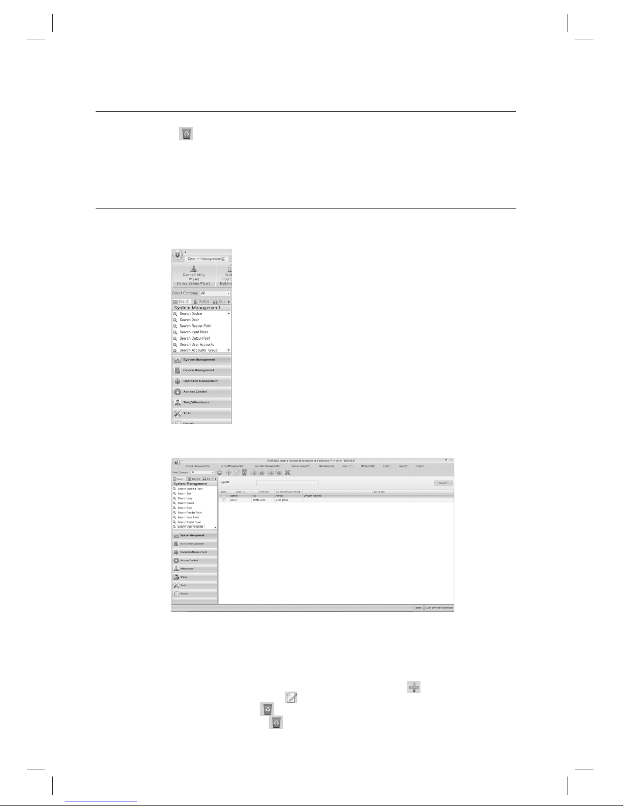
94_ system management
system management
Click Delete < > in the tool bar.
When you are prompted to delete the item, click [Yes].
USER ACCOUNTS SETTING [SEARCH]
In the left [Search] tab of the main screen, select [System Management] > [Search User Accounts].
In the right pane of the main screen, the User Account search screen appears.
Provide the search criteria according to the item to fi nd.
Click Search to start searching.
In the search list, you can also add, edit or delete items. From the tool bar, click < > to move to the input
screen. Select a searched item and click <
> to move to the edit (change) screen.
Select a searched item and click <
> to delete it. If you want to delete multiple items at once, check all the items
to delete in the search list and click < > to delete them all at once.
2.
3.
1.
2.
3.
4.
J
Page 95
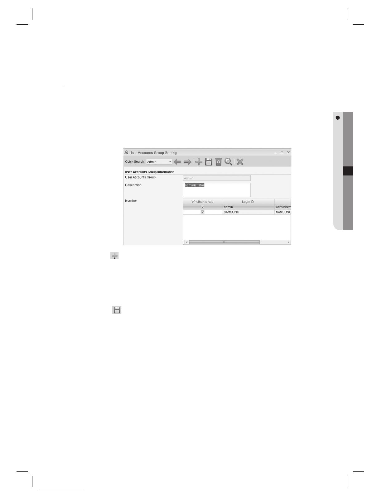
English Englis_ English _95
SYSTEM MANAGEMENT
USER ACCOUNTS GROUP SETTING [ADD]
Adds a permission group to which a user belongs.
- User Accounts Group: Enter the name of the user accounts group to be added.
- Description: Enter the user group’s description.
- Member: Add member IDs to the user group to be added. (Allows multiple selection)
From the upper menu, select [System Management] > [User Accounts Group Setting].
Click Add <
> in the tool bar.
Enter the [User Accounts Group].
Select [Whether to Add] of members to be included to the user accounts group in the [Member] list.
Click Save <
> in the tool bar.
1.
2.
3.
4.
5.
Page 96
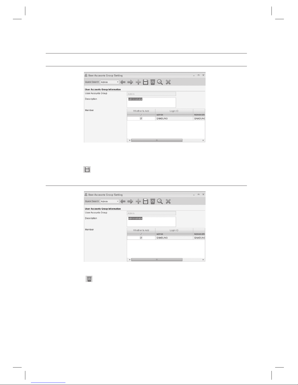
96_ system management
system management
USER ACCOUNTS GROUP SETTING [EDIT]
Select an item to change using [Quick Search] in the tool bar.
Make changes as necessary.
Click Save <
> in the tool bar.
USER ACCOUNTS GROUP SETTING [DELETE]
Select an item to delete using [Quick Search] in the tool bar.
Click Delete <
> in the tool bar.
When you are prompted to delete the item, click [Yes].
1.
2.
3.
1.
2.
3.
Page 97
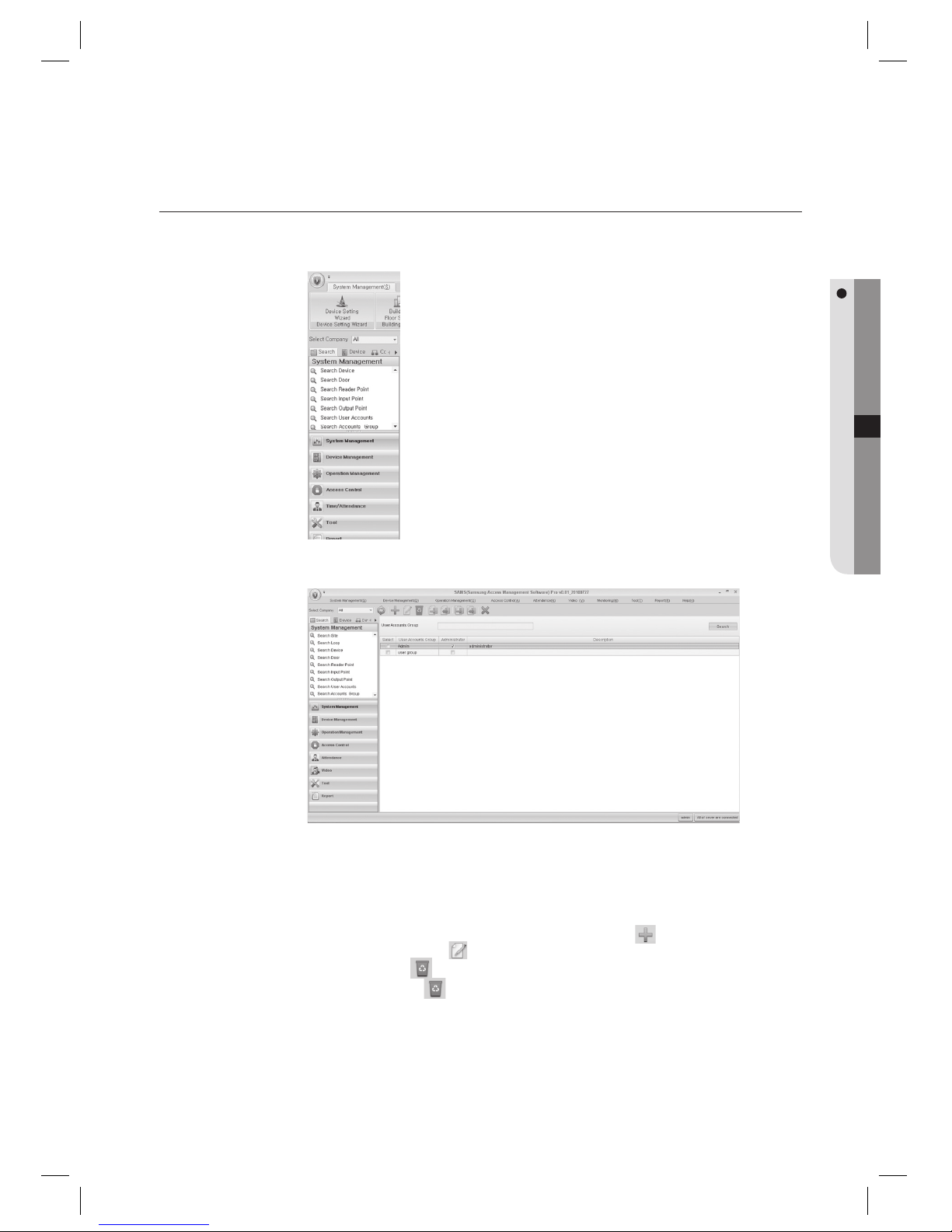
English Englis_ English _97
SYSTEM MANAGEMENT
USER ACCOUNTS GROUP SETTING [SEARCH]
In the left [Search] tab of the main screen, select [System Management] > [Search Accounts Group].
In the right pane of the main screen, the User Group search screen appears.
Provide the search criteria according to the item to fi nd.
Click Search to start searching.
In the search list, you can also add, edit or delete items. From the tool bar, click < > to move to the input
screen. Select a searched item and click < > to move to the edit (change) screen.
Select a searched item and click < > to delete it. If you want to delete multiple items at once, check all the items
to delete in the search list and click < > to delete them all at once.
1.
2.
3.
4.
J
Page 98
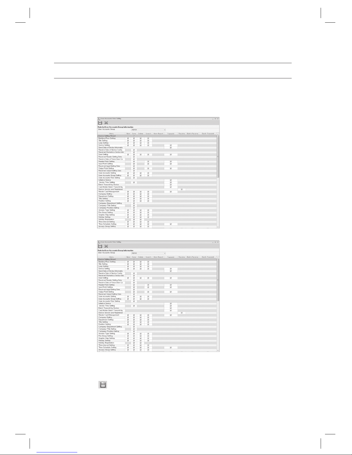
98_ system management
system management
USER ACCOUNTS ROLE SETTING [ADD]
You can grant or decline permissions of creating, saving, deleting, searching, report viewing, data transfer, and batch data
transfer to each user accounts group registered.
From the upper menu, select [System Management] > [User Accounts Role Setting].
Select a [User Accounts Group].
Grant permissions of each menu item (New, Save, Delete, Search, View Report, Transmit, Receive, Batch
Receive and Batch Transmit).
Click Save <
> in the tool bar.
Only those users who log in as a user account belonging to [Admin Group] can access [User Accounts Setting], [User
Accounts Group Setting], and [User Accounts Role Setting].
1.
2.
3.
4.
J
< SAMS Pro >
< SAMS Pro Lite >
Page 99
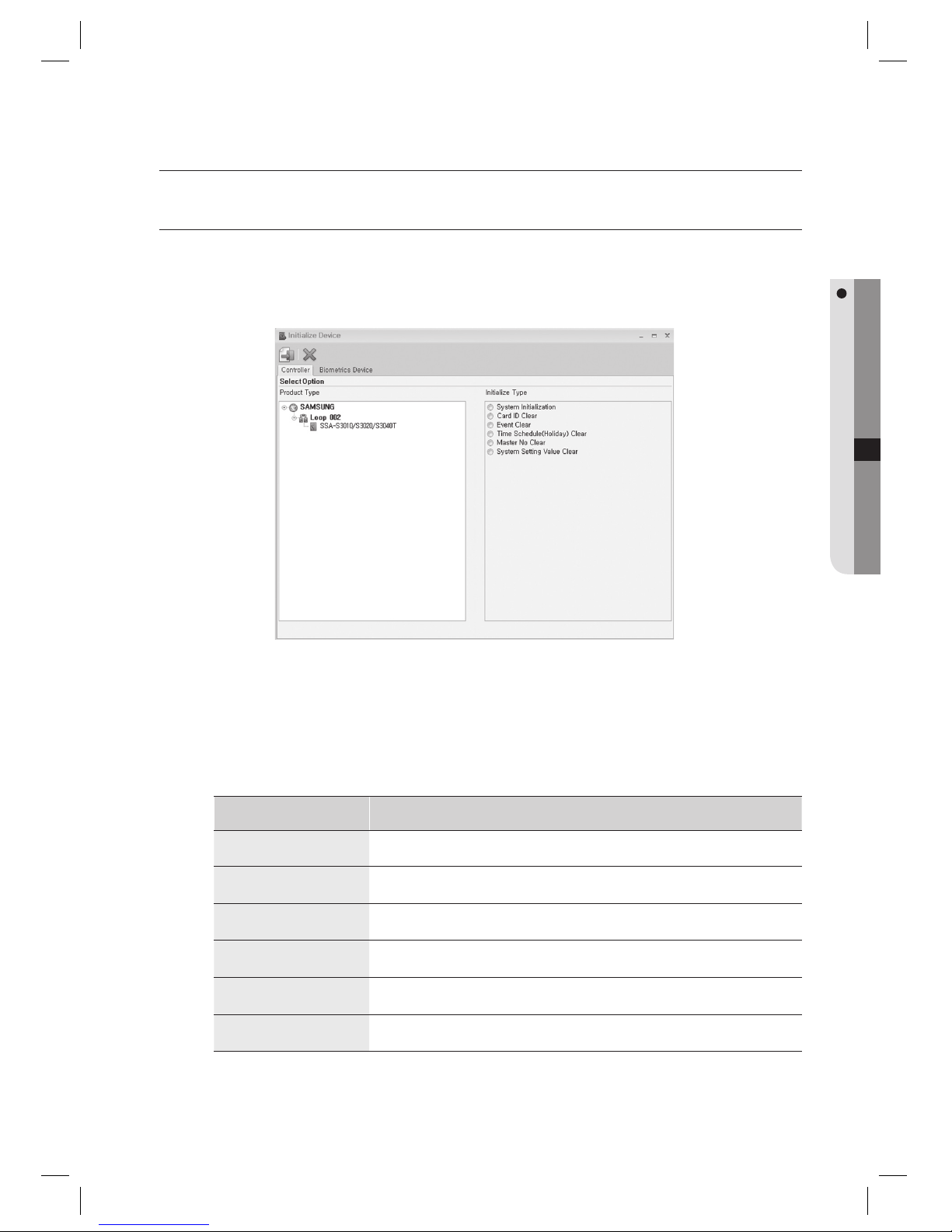
English Englis_ English _99
DEVICE MANAGEMENT
device management
INITIALIZE DEVICE
(Ú This is not available in SAMS Pro Lite.)
You can select a device and initialize desired items.
From the upper menu, select [Device Management] > [Initialize Device].
Select the [Controller] tab for controller initialization, or [Biometrics Device] tab for biometrics reader device
initialization.
Select the [Product Type] to be initialized.
Select the [Initialization Type].
Initialization Type Descriptions
System Initialization
Initializes the system and deletes all information added (ID, fi ngerprint, event, time schedule,
and holiday), and restores the factory default values.
Card ID Clear
Deletes all ID and fi ngerprint information added to the device.
Event Clear
Deletes all event information (normal, alarm) added to the device.
Time Schedule (Holiday) Clear
Deletes all time schedule and holiday information added to the device.
Master No Clear
Deletes the Master Card information added to the device.
System Setting Value Clear
Deletes all information other than ID and fi ngerprint information added to the device.
1.
2.
3.
4.
Page 100
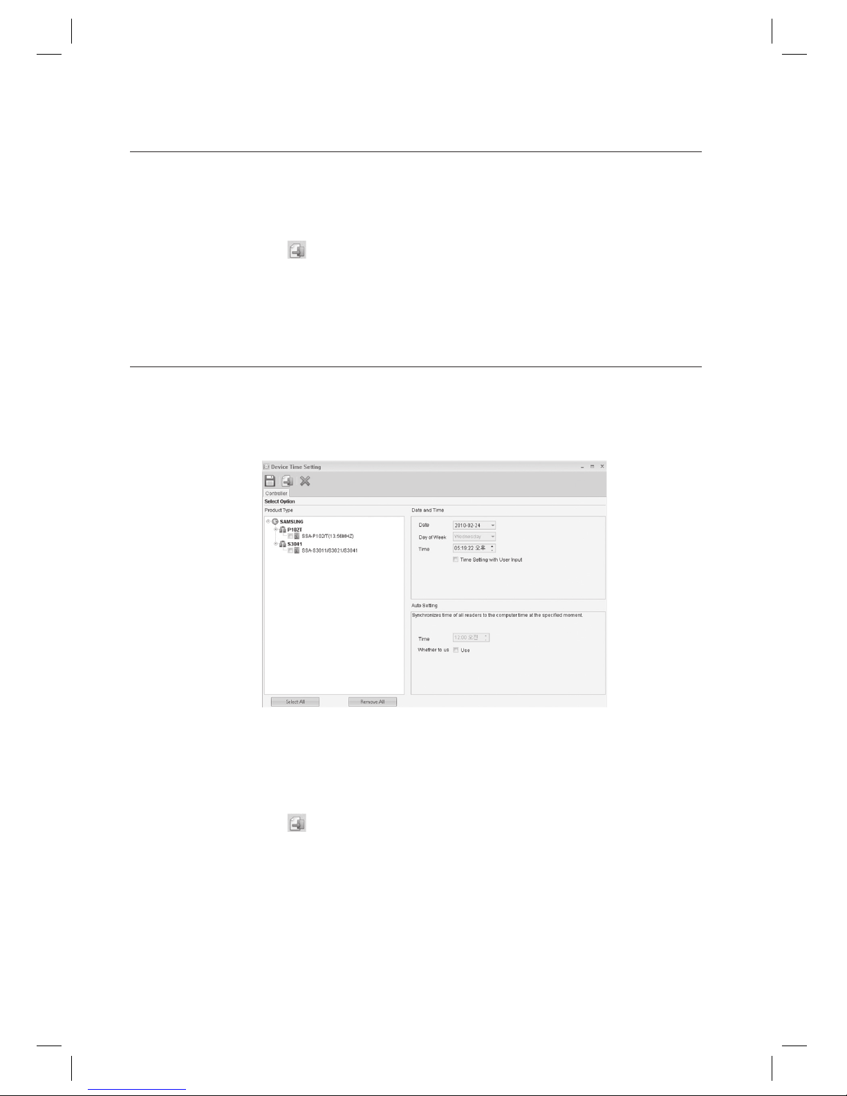
100_ device management
device management
Initializing deletes all information confi gured after the installation and may lose important stored data.
Be cautious with initializing the product.
Click Transmit button < > in the toolbar to send the confi guration to the device.
To confi rm the data transmission and its result, run the [Monitoring] > [Integrated Monitoring] from the toolbar
before clicking the transmit button. The data transmission result of each item will be displayed in the [Auditing Log]
window of the integrated monitoring screen.
DEVICE TIME SETTING
(Ú This is not available in SAMS Pro Lite.)
You can set the time of each device using the SAMS Pro.
From the upper menu, select [Device Management] > [Device Time Setting].
Select the [Product Type] to be set.
Check [Date], [Day of Week] and [Time]. Displayed time changes according to the local computer’s current time.
To specify a certain time point, check [Time Setting with User Input]. Enter the [Date], and [Time].
Click Transmit button <
> in the toolbar to send the confi guration to the device.
To confi rm the data transmission and its result, run the [Monitoring] > [Integrated Monitoring] from the toolbar
before clicking the transmit button.
The data transmission result of each item will be displayed in the [Auditing Log] window of the integrated monitoring
screen.
For automatic synchronization of device time of all connected devices to the computer time, specify the
synchronization time in [Auto Setting].
Set [Time] for automatic time updating of [Auto Setting]. Time information of all connected devices will be
synchronized to the computer’s time on the specifi ed time.
J
5.
J
1.
2.
3.
4.
5.
J
6.
7.
 Loading...