

Page 1
KD04-00046K
Rev. 1.00
사용 설명서 /
SRP-370
감열식 프린터 / 热敏式打印机 / THERMAL PRINTER
用户手册
/
USER'S MANUAL
www.samsungminiprinters.com
Page 2
안전상의 경고
제품을 올바르게 사용하여 위험이나 물적 손해를 미리 방지하기 위한
내용이므로 반드시 지켜 사용해 주세요.
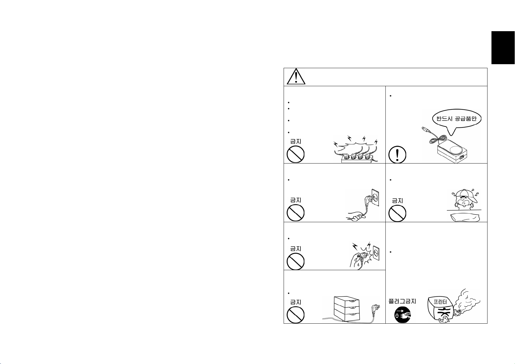
경고
표시사항 위반시 심각한 상해나 사망이 발생할 가능성이 있습니다.
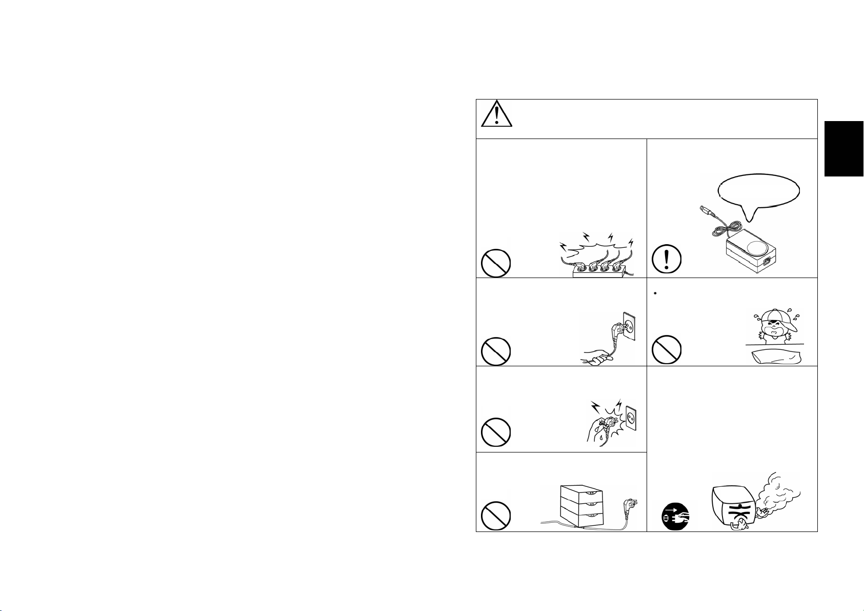
한 콘센트에 여러 제품의 전원플러그를
동시에 꽂아 사용하지 마세요.
발열 및 발화되어 위험합니다.
전원플러그에 이물질이나 물기가 묻어
있는 경우에는 잘 닦은 다음 사용하세요.
전원콘센트의 구멍이 헐거울때는 전원
플러그를 꽂지마세요.
멀티콘센트는 규격제품을 사용하세요.
아답터는 공급된 제품만을 사용하세요.
다른 아답터를 사용하면 위험합니다.
Korean
Korean
전원플러그를 뺄때는 전원코드를 잡아
당기지 마세요.
코드가 상처를 입어 화재나 고장의
원인이 됩니다.
젖은 손으로 전원플러그를 꽂거나 뽑지
마세요.
감전의 위험이 있습니다.
전원코드를 무리하게 구부리거나
무거운 물건으로 눌러 파손되지 않도록
하세요.
화재의 원인이 됩니다.
비닐팩은 어린이의 손에 닿지 않는
곳에 잘 보관하세요.
어린이가 비닐팩을 머리에 쓰면
위험합니다.
제품에서 연기가 나거나 이상한 냄새
또는 소리가 나는 등의 이상 발생시는
바로 전원을 끈 후 아래의 조치를 취해
주세요.
제품에 이상이 발생시는 바로 프린터
본체의 전원을 끈 다음 반드시 전원
플러그를 콘센트에서 뽑아주세요.
연기가 나지 않는 것을 확인하고
구입처로 수리를 의뢰해 주세요.
1
Page 3
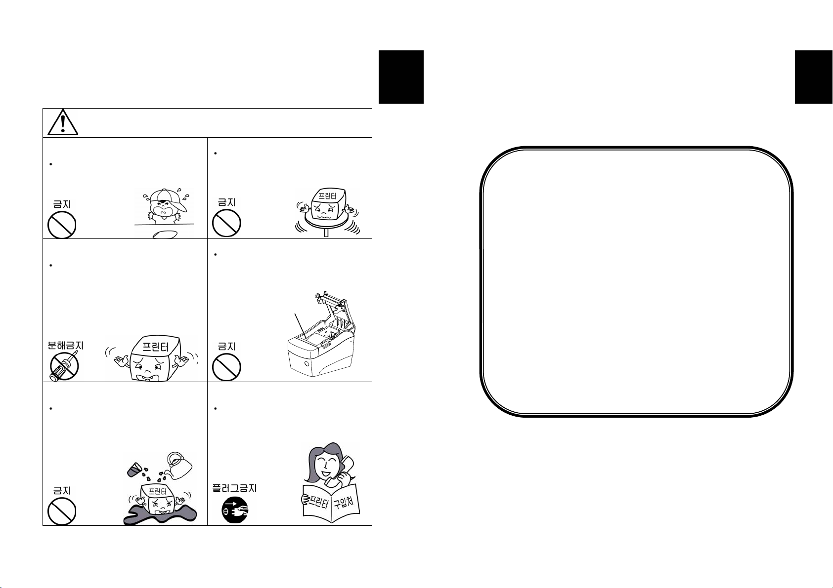
주의
표시사항 위반시 경미한 상해나 제품손상이 발생할 가능성이 있습니다.
방습제는 어린이의 손에 닿지 않는
곳에 잘 보관하세요.
어린이가 방습제를 먹으면 위험합니다.
승인된 부품을 사용하고 함부로 분해,
수리, 개조하지 마세요.
제품이 손상될 수 있으므로 구입처에
문의하세요.
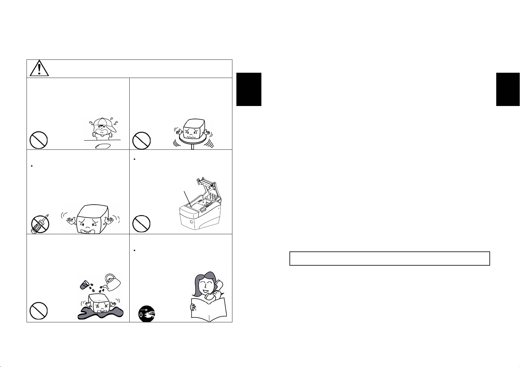
프린터의 본체 내부에 물이나 이물질이
들어가지 않도록 주의하세요.
경우에는 먼저 프린터 본체의 스위치를
끄고 전원플러그를 콘센트에서 뺀 다음
구입처로 연락해 주세요.
본체 내부에 물이나 이물질이 들어간
안정된 장소에 설치하세요.
넘어지면 제품이 파손되거나 다칠 수
있습니다.
헤드 면을 손으로 만지지 마세요.
헤드 면을 손으로 만지게 되면, 미열에
의한 화상 및 인쇄 품질 저하를 초래할
수 있습니다.
헤드
제품을 고장난 상태에서 사용하지
마세요. 화재, 감전의 원인이 됩니다.
바로 본체의 전원스위치를 끄고 전원
플러그를 콘센트에서 뺀 다음 구입처로
연락해 주세요.
Korean
저작권자 (주)삼성전기 2005
(C) Copyright SAMSUNG ELECTRO-MECHANICS Co., Ltd. 2005
All rights reserved
이 사용설명서와 제품은 저작권법에 의해 보호되어 있습니다.
(주)삼성전기의 사전 서면 동의없이 사용설명서 및 제품의 일부
또는 전체를 복사, 복제, 번역 또는 전자매체나 기계가 읽을 수 있는
형태로 바꿀 수 없습니다. 이 사용설명서와 제품은 인쇄상의
잘못이나 기술적인 잘못이 있을 수 있으며 사전 통보없이 이러한
내용들이 바뀔 수 있습니다.
VUS06:326:5, ᾗ는 삼성전기의 등록상표입니다.
이 기기는 업무용으로 전자파 적합등록을 한 기기이오니 판매자
또는 사용자는 이 점을 주의하시기 바라며 만약 잘못 판매 또는
구입하였을 때에는 가정용으로 교환하시기 바랍니다.
Korean
2
3
Page 4

사용시 주의사항
프린터와 같은 전자 제품은 정전기에 의해 쉽게 훼손될 수 있습니다.
정전기로부터 프린터를 보호하기 위해서는 프린터 후면부에 케이블을 연결하거나
제거하기 전에 반드시 프린터 전원을 끄십시오. 만약 프린터가 정전기로부터 손상을
입었을 경우에는 가까운 구입처에 문의하십시오.
제품소개
SRP-370/372 프린터는 ECR (Electronic Cash Register), POS (Point Of Sales), 컴퓨터
주변기기와 같은 전자 제품과 연결하여 사용하도록 만들어졌습니다.
프린터의 주요 특징
1. 초당 47라인의 고속 인쇄(1/6인치 Feed 기준)
2. 저소음 열전사 방식 인쇄
3. 직렬포트 (RS-232), 병렬포트 (Parallel) 및 USB 지원
(단, 직렬로 인쇄하려면 별도장비 구입 필요)
4. 데이터 버퍼 내장 (인쇄 중에도 인쇄 데이터를 수신함)
5. 주변장치 구동 회로를 통해 금전 등록기와 같은 외부 장치 제어
6. 최대 64배까지 확대 인쇄 가능
7. 바코드 인쇄 기능 (단, 별도의 바코드 명령어를 이용하여 인쇄해야 함)
8. 다양한 인쇄 농도 선택 가능 (선택 스위치를 통한 조정)
프린터를 새로 구입하신 분들은 사용 전에 이 설명서에 있는 내용을
주의 깊게 읽어보시기 바랍니다.
Korean
목차
1장. 프린터 설치 및 기본 사용법 ................................................ 6
1-1.
포장 풀기...................................................................... 6
1-2.
커넥터 확인하기............................................................. 7
1-3.
컴퓨터와 연결하기.......................................................... 8
1-4.
현금 서랍과 연결하기...................................................... 8
1-5.
전원 연결하기........................................................... ..... 9
1-6.
용지 넣기와 교환하기.....................................................10
1-7.
용지 감지센서 위치 조절하기 ..........................................12
1-8.
프린터 기능 사용하기.....................................................13
1-9.
딥 스위치 설정하기........................................................14
1-10.
메모리 스위치 설정하기 ................................................16
2장. 16진수 인쇄 기능..............................................................18
3장. 셀프 테스트.....................................................................19
4장. 코드표 ............................................................................20
부록 ......................................................................................37
A.
커넥터 ............................................................................37
B.
프린터 청소 .....................................................................40
C.
사양 ...............................................................................41
Korean
4
5
Page 5
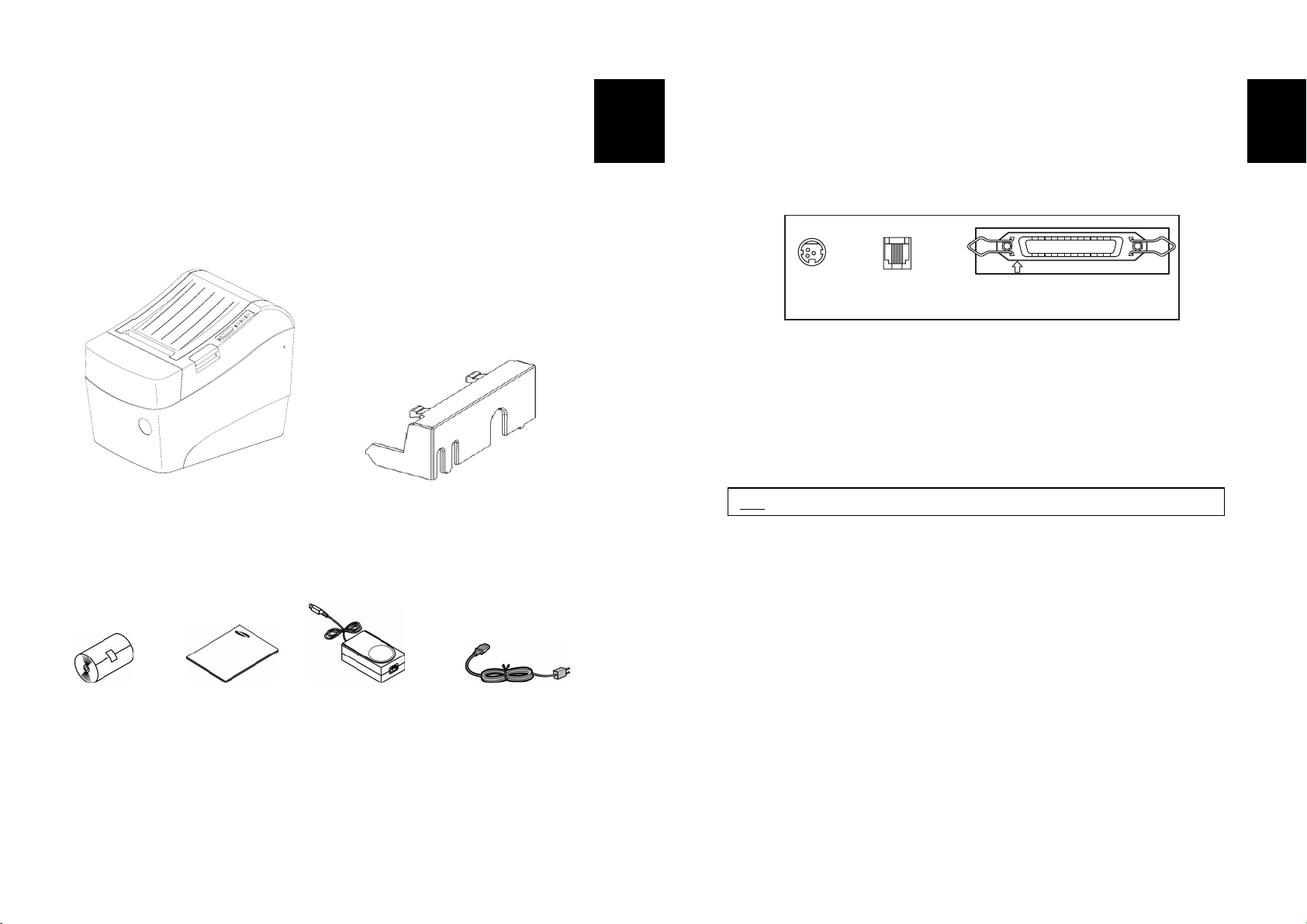
1장. 프린터 설치 및 기본 사용법
1-1. 포장 풀기
아래 내용물을 확인하신 후 빠지거나 잘못 된 것이 있다면 구입하신 곳으로
연락하세요.
SRP-370/372 프린터 케이블 커버
용지 사용설명서 AC 어댑터 전원코드
Korean
1-2. 커넥터 확인하기
SRP-370/372 시리즈 프린터는 병렬케이블 (Parallel) 포트를 기본적으로 제공하며
직렬케이블 (Serial, RS-232) 포트는 옵션으로 제공합니다.
POWER DK
PARALLEL
전원
커넥터
이 프린터를 ECR, POS 또는 컴퓨터와 연결하여 사용하려면 프린터 뒷면의 커넥터에
제공된 케이블을 이용하여 연결하세요.
주의 : 모든 케이블은 프린터와 호스트가 꺼진 상태에서 연결하세요.
현금서랍
커넥터
병렬케이블 커넥터
Korean
6
7
Page 6
1-3. 컴퓨터와 연결하기
제공된 케이블을 이용하여 연결하세요.
1. 병렬케이블을 프린터 뒷면의 PARALLEL 표시부에 연결하세요.
2. 케이블의 나사를 조이세요.
3. 병렬케이블의 다른 한 쪽 끝을 컴퓨터의 프린터 포트에 연결하세요.
1-4. 현금 서랍과 연결하기
현금 서랍 연결 케이블을 프린터 후면의 현금 서랍 커넥터에 연결하세요.
경고
프린터 사양에 맞는 현금 서랍을 사용하십시오.
사양에 맞지 않는 현금 서랍을 사용하였을 경우에는 현금 서랍과 프린터에 이상이 생길
수 있습니다.
주의
현금 서랍 연결 커넥터에 전화선을 사용하지 마십시오.
전화선으로 연결했을 경우 전화선과 프린터에 이상이 생길 수 있습니다.
Korean
1-5. 전원 연결하기
주의
전원을 연결하거나 제거할 때 반드시 전원공급장치를 콘센트에서 빼고
제거하십시오. 그렇지 않으면 전원공급장치나 프린터에 영향을 미칠 수 있습니다.
전원공급장치와 콘센트의 전압이 맞지 않는다면 판매처에 연락하시고
전원공급장치를 연결을 하지 마십시오. 그렇지 않으면 전원공급장치나 프린터에
영향을 미칠 수 있습니다.
1. 프린터의 전원스위치를 반드시 끄고 전원공급장치의 코드를 콘센트에서
빼십시오.
2. 전원공급장치와 전원 콘센트의 용량을 확인하려면 전원공급장치의 라벨을
확인하십시오.
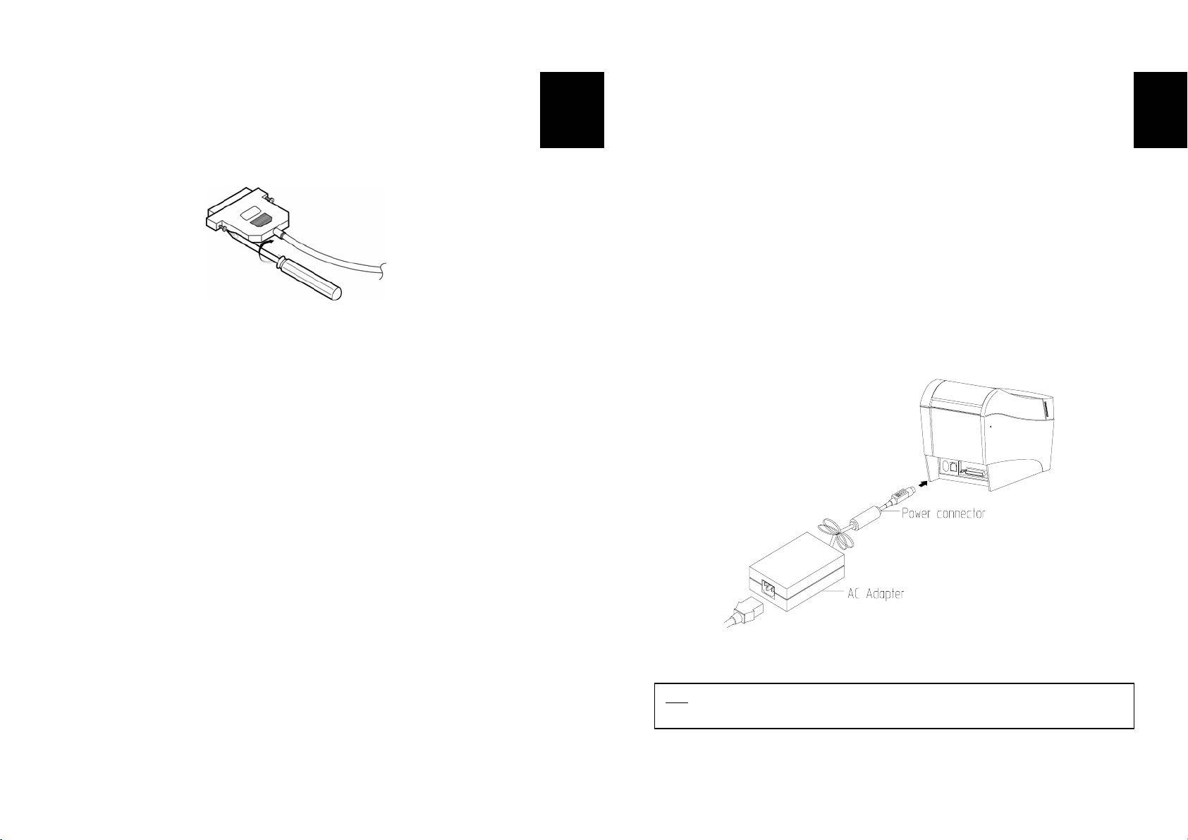
3. 아래의 그림과 같이 전원공급장치의 연결부위가 평평한 면이 위로 향하게 하여
프린터에 연결하십시오.
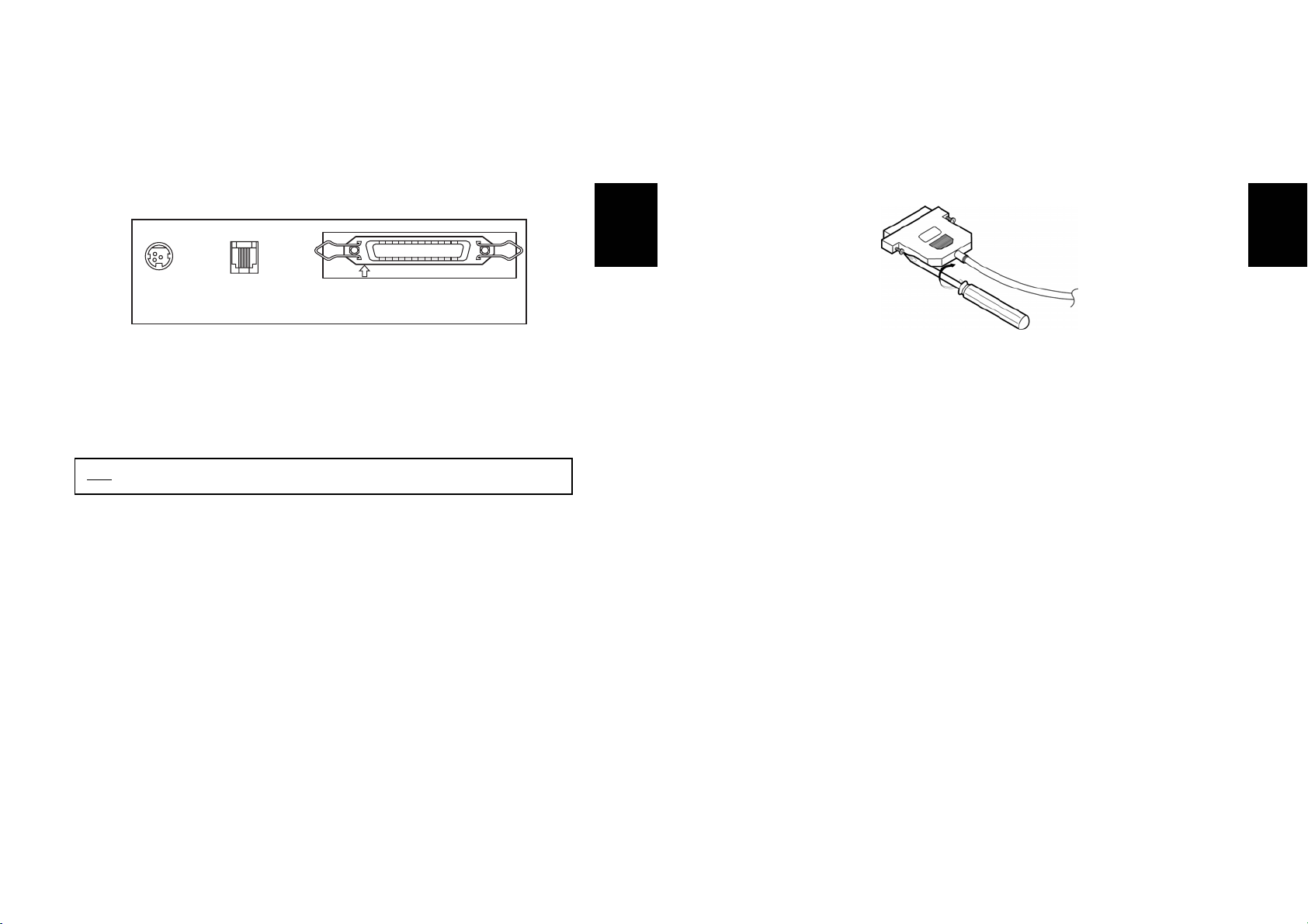
참고 : 전원공급장치를 제거할 때에는 연결부위의 화살표부분을 단단히 잡고 똑바로
뽑아주세요.
Korean
8
9
Page 7
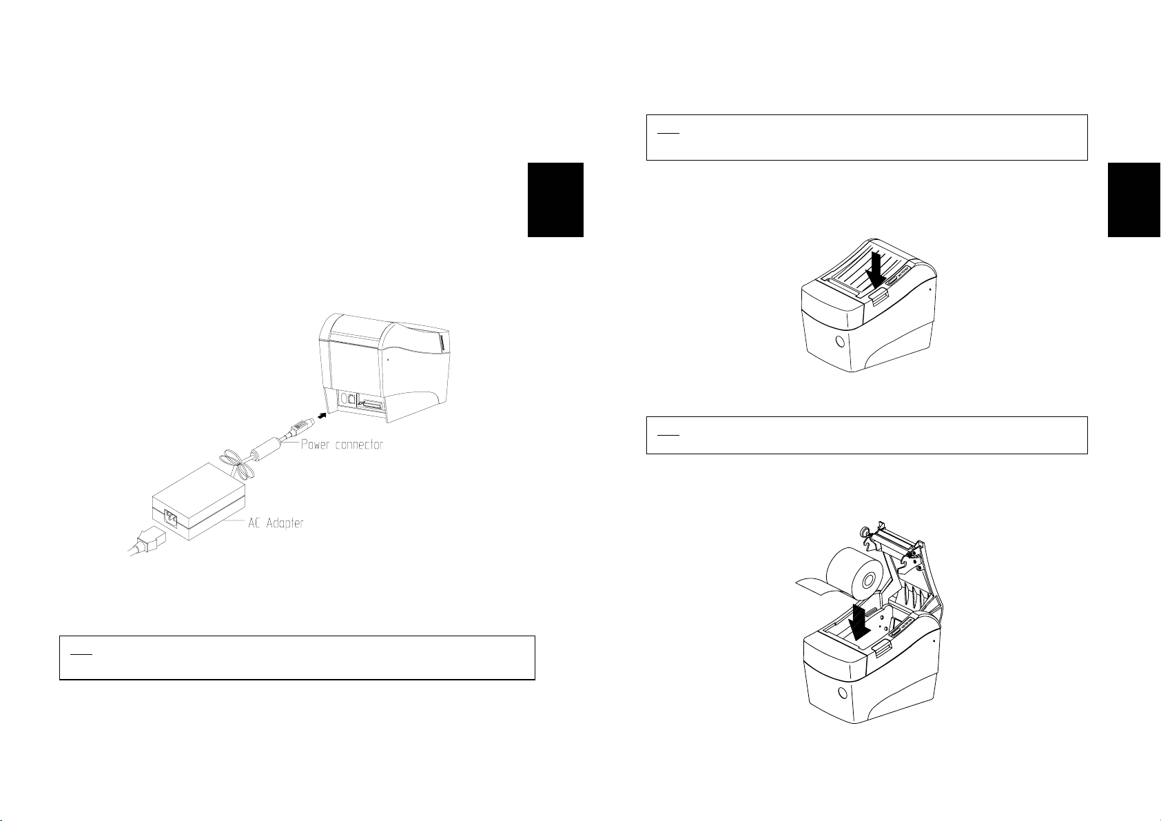
1-6. 용지 넣기와 교환하기
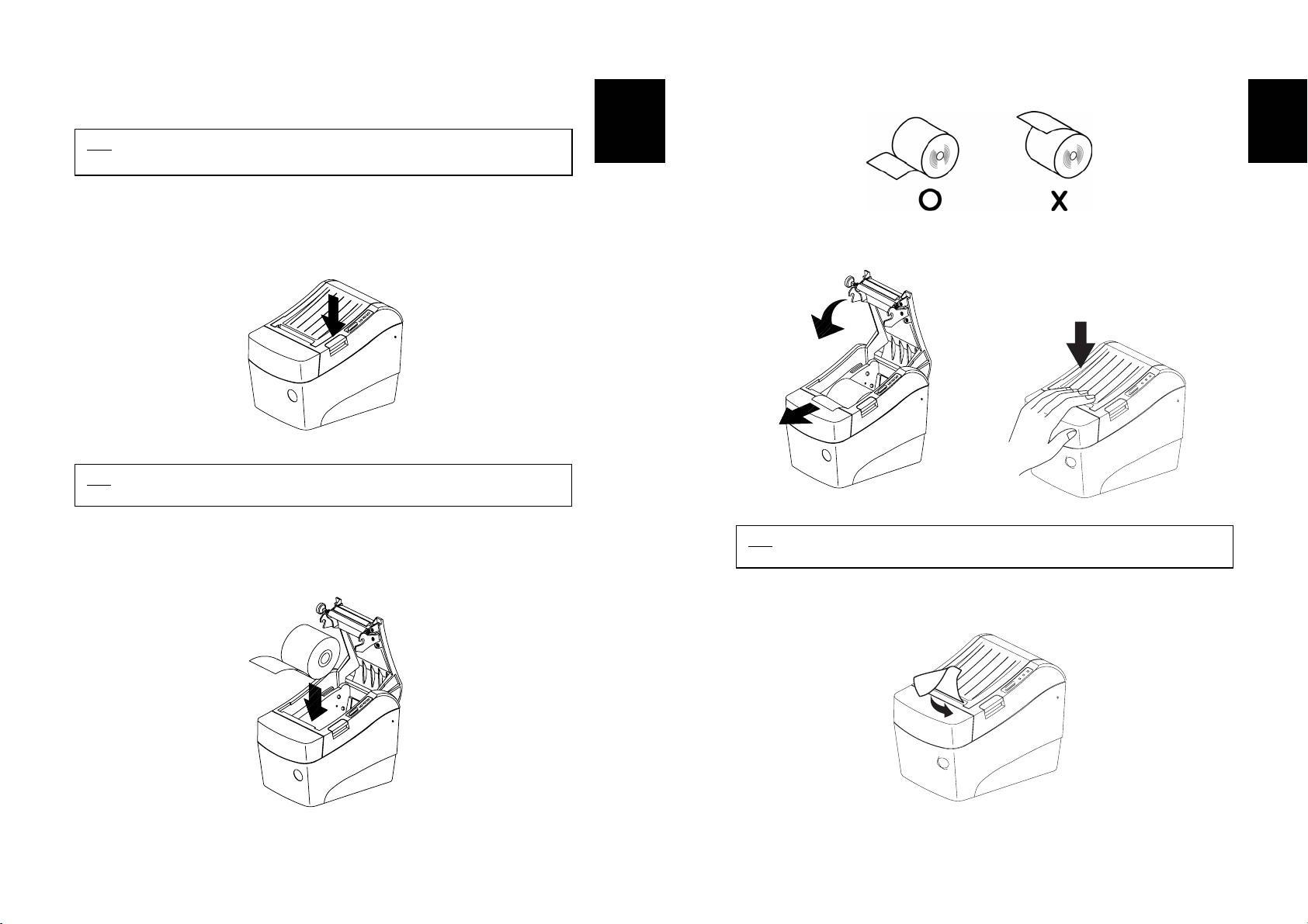
참고 : 규격에 맞는 용지를 사용하십시오. 그렇지 않으면 프린터가 용지 없음을
정확하게 인식하지 못하기 때문에 잘 풀리는 용지를 사용해야 합니다.
1. 데이터 손실이 있을 수 있으니, 프린터가 데이터를 받고 있지 않을 때 용지를
교환하세요.
커버열림
2.
버튼을 눌러 프린터의 커버를 여세요.
Korean
5. 용지를 넣을 때에는 용지의 방향이 정확한지 확인하세요.
6. 그림과 같이 용지 끝을 약간 앞으로 끌어내린 후 커버를 닫으세요.
Korean
P
o
w
e
r
E
r
r
o
r
p
a
p
e
r
F
e
e
d
참고 : 프린터가 동작하는 동안에는 프린터 커버를 열지 마세요.
프린터가 손상될 수 있습니다.
3. 용지를 교환하는 경우라면 다 쓴 용지는 제거하세요.
4. 아래 그림과 같이 용지를 넣으세요.
참고 : 커버를 닫을 때 용지가 롤러에 걸릴 수 있도록 커버의 가운데를 확실하게
눌러주십시오.
7. 그림과 같이 용지를 잘라 내세요.
Power
Error
paper
Feed
10
11
Page 8
1-7. 용지 감지센서 위치 조절하기
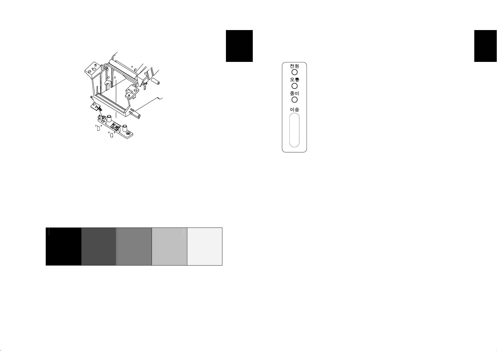
1) 용지 감지센서에는
용지없음을 인식하기 위해서는 위의 그림과 같이 센서가 "a"에 위치해야 하는데,
이는 공장에서 출하되는 기본사양 입니다. 블랙마크를 인식하기 위해서는 센서가
"b"에 위치해야 합니다.
2) 블랙마크의 광학농도(O.D)는 적어도 0.6 이상이어야 안정적으로 인식이 됩니다.
용지의 블랙마크 농도가 에러동작의 원인이 될 수도 있으므로 확인하시기 바랍니다.
3) O.D값 표(참조)
1.4 0.9 0.6 0.3 0.2
용지없음
인식과
블랙마크
인식의 두 가지 기능이 있습니다.
Korean
1-8. 프린터 기능 상용하기
제어판
전원
전원 표시등은 프린터에 전원이 켜져 있을 경우 켜집니다.
오류
오류가 발생하였을 때 켜집니다.
종이
이 표시등이 켜지면 용지가 거의 다 소모되었거나 용지가 없음을 나타냅니다.
새 용지로 교환하거나 용지를 넣으십시오.
이 표시등이 깜빡거리면 SELF TEST 대기 상태이거나 매크로 실행 대기중임을
나타냅니다.
이송버튼
버튼은 ESC c 5 명령어에 의해서 사용 불가능하게 할 수 있습니다.
용지 한 라인을 배출하기 위해서는 이송버튼을 한 번 누르십시오.
이송버튼을 계속 누르고 있으면 용지를 연속적으로 배출 할 수 있습니다.
Korean
12
13
Page 9

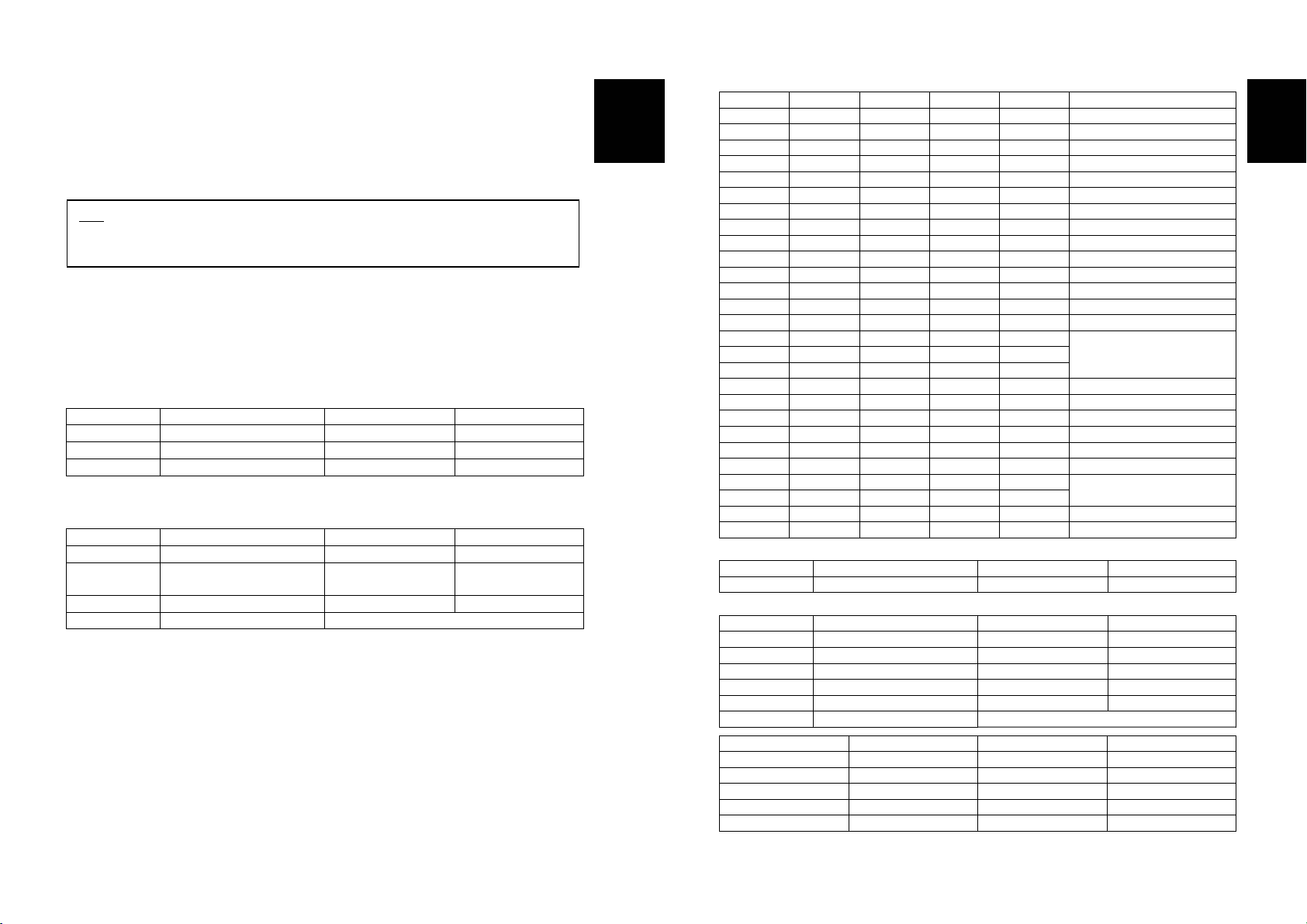
1-9. 딥 스위치 설정하기
직렬포트 (RS-232C, RS-485)
선택스위치 1 설정
Switch No. 기능 ON OFF 기본설정
SW1-1 OFF
SW1-2
SW1-3 흐름제어
SW1-4 없음 -- OFF
SW1-5 오토 커터 기능 해제 동작 OFF
SW1-6 용지 2 칼라 단색 OFF
SW1-7 없음 -- OFF
SW1-8 없음 -- OFF
* 전송 속도 테이블
SW1-1 SW1-2 전송 속도 비고
OFF OFF 9600 Baud
ON OFF 19200 Baud
OFF ON 38400 Baud
ON ON 115200 Baud 기본 설정
선택스위치 2 설정
Switch No. 기능 ON OFF 기본설정
SW2-1 OFF
SW2-2 OFF
SW2-3
SW2-4 Historical 제어 동작 해제 OFF
SW2-5 없음 -- OFF
SW2-6 통신 상태 설정 메모리 스위치 딥 스위치 OFF
SW2-7 없음 -- OFF
SW2-8 용지 폭 2인치 인쇄 3인치 인쇄 OFF
* 인쇄 농도 테이블
SW 2-1 SW 2-2 SW 2-3 인쇄농도 비고
ON ON ON 130%
OFF ON ON 120%
ON OFF ON 110%
OFF OFF ON 105%
OFF OFF OFF 100% 기본 설정
ON OFF OFF 95%
OFF ON OFF 90%
ON ON OFF 80%
전송 속도 * 아래 테이블 참조
Hardware
(DTR/DSR)
인쇄 농도 * 아래 테이블 참조
Software
(Xon/Xoff)
OFF
OFF
OFF
Korean
병렬/USB 포트
선택스위치 2 설정
Switch No. 기능 ON OFF 기본설정
SW2-1 OFF
SW2-2 OFF
SW2-3
SW2-4 Historical 제어 동작 해제 OFF
SW2-5 없음 -- OFF
SW2-6 통신 상태 설정 메모리 스위치 딥 스위치 OFF
SW2-7 없음 -- OFF
SW2-8 용지 폭 2인치 인쇄 3인치 인쇄 OFF
* 인쇄 농도 테이블
SW 2-1 SW 2-2 SW 2-3 인쇄농도 비고
ON ON ON 130%
OFF ON ON 120%
ON OFF ON 110%
OFF OFF ON 105%
OFF OFF OFF 100% 기본 설정
ON OFF OFF 95%
OFF ON OFF 90%
ON ON OFF 80%
※ 오토 커터 (Auto Cutter) 사용 선택
SW 5 ON 오토 커터 사용하지 않음
동작 연속 인쇄 시 오토 커터 동작하지 않음
인쇄 농도 * 아래 테이블 참조
OFF
선택스위치 2
Korean
14
15
Page 10
1-10. 메모리 스위치 설정하기
이 프린터에는 소프트웨어 스위치인 메모리 스위치가 있습니다.
"Memory Switch setting utility"를 이용하여 아래의 표와 같이 메모리 스위치를 ON 또는
OFF로 설정할 수 있습니다. (기본설정: 모두 OFF)
참고 : 메모리 스위치는 두 가지 방법으로 변경할 수 있습니다.
- Memory Switch setting utility
- ESC/POS 명령어 제어
메모리 스위치 설정 값은 NV 메모리에 저장됩니다. 그러므로 프린터에 전원이 공급되지
않아도 유지될 수 있습니다.
MSW1
스위치 기능
1~4 없음 -- OFF로 고정
5 자동 라인 피딩 동작 해제
6~8 없음 -- OFF로 고정
MSW2
스위치 기능
1 문자 설정 Font B (9 x 24) Font A (12 x 24)
2 오토 커터 기능
3 없음 -- OFF로 고정
4~8 문자표 설정 아래 표 참조
ON OFF
ON OFF
완전 잘림
(Full Cut)
(Partial Cut)
부분 잘림
Korean
MSW2-8 MSW2-7 MSW2-6 MSW2-5 MSW2-4 문자표
OFF OFF OFF OFF OFF Page 0 437
OFF OFF OFF OFF ON Page 1 Katakana
OFF OFF OFF ON OFF Page 2 850
OFF OFF OFF ON ON Page 3 860
OFF OFF ON OFF OFF Page 4 863
OFF OFF ON OFF ON Page 5 865
OFF OFF ON ON OFF Page 16 1252
OFF OFF ON ON ON Page 17 866
OFF ON OFF OFF OFF Page 18 852
OFF ON OFF OFF ON Page 19 858
OFF ON OFF ON OFF 없음
OFF ON OFF ON ON Page 22 864
OFF ON ON OFF OFF Page 23 Thai42
OFF ON ON OFF ON Page 24 1253
OFF ON ON ON OFF
OFF ON ON ON ON
ON OFF OFF OFF OFF
ON OFF OFF OFF ON Page 28 1251
ON OFF OFF ON OFF Page 29 737
ON OFF OFF ON ON 없음
ON OFF ON OFF OFF Page 31 Thai16
ON OFF ON OFF ON 없음
ON OFF ON ON OFF Page 33 1255
ON OFF ON ON ON
ON ON OFF OFF OFF
ON ON OFF OFF ON Page 36 855
ON ON OFF ON OFF Page 37 857
MSW8
스위치 기능 ON OFF
1~8 없음 -- OFF로 고정
MSW9
스위치 기능 ON OFF
1 없음 -- OFF로 고정
2 데이터 길이 7 비트 8 비트
3 패리티 (Parity) Even Odd
4 패리티 체크여부 체크함 체크 안 함
5 흐름제어 DTR/DSR XON/XOFF
6~8 전송속도 아래 표 참조
MSW9-8 MSW9-7 MSW9-6 전송속도
OFF OFF OFF 9600
OFF OFF ON 19200
OFF ON OFF 38400
OFF ON ON 57600
ON OFF OFF 115200
없음
없음
Korean
16
17
Page 11

2장. 16진수 인쇄기능
이 기능은 고급 사용자들에게 프린터가 주고 받는 데이터를 정확히 확인할 수 있도록
하며, 소프트웨어적인 문제를 발견할 수 있도록 합니다. 프린터의 16진수 인쇄 기능을
사용 할 경우 모든 데이터와 명령어를 16진수 형태로 인쇄하기 때문에 특별한
명령어를 찾는데 도움이 됩니다.
16진수 인쇄기능을 사용하기 위해서는 다음과 같은 단계를 따르십시오.
1. 프린터의 전원을 끈 다음, 프린터 커버를 여세요.
이송
2.
3. 프린터 커버를 닫으면 16진수 인쇄 모드가 됩니다.
4. 프린터로 데이터를 보내는 프로그램을 실행하세요.
5. 16진수 인쇄가 다 끝났을 경우에는 프린터의 전원을 끄세요.
6. 프린터의 전원을 다시 켜면 16진수 인쇄모드가 해제됩니다.
버튼을 누른 상태에서 프린터 전원을 켜세요.
프린터는 모든 데이터를 2열로 나누어서 인쇄할 것입니다.
첫번째 열은 16진수 코드를 나타내고
두번째 열은 16진수 코드에 해당하는 ASCII 문자를 나타냅니다.
0000: 1B 21 00 1B - 26 02 40 40 ¦ . ! . . & . @ @
0008: 40 40 02 0D - 1B 44 0A 14 ¦ @ @ . . . D . .
0010: 1E 28 28 28 - 00 01 0A 41 ¦ . ( ( ( . . . A
z 해당되는 ASCII 코드가 없을 경우에는 마침표 (.) 로 인쇄됩니다.
z 16진수 인쇄모드상태에서는 DLE EOT 과 DLE ENQ 명령어를 제외한
모든 명령어가 사용 불가능하게 됩니다.
Korean
3장. 셀프 테스트
셀프 테스트는 프린터에 어떤 이상이 있는지를 체크합니다. 프린터가 제대로 작동하지
않는다면 구입하신 곳으로 연락하시기 바랍니다. 셀프 테스트 절차는 다음과 같습니다.
1. 용지가 제대로 끼워져 있는지 확인하세요.
이송
2.
3. 프린터는 ROM의 버전과 딥 스위치 설정 상태와 같은 프린터의 현재 상태를
4. 프린터의 현재 상태를 인쇄하고 난 후, 다음과 같은 문구를 인쇄한 후 멈춥니다.
5. 인쇄를 계속 하기 위해서는
프린터는 미리 제작된 문자 형식을 인쇄합니다.
6. 셀프 테스트는 자동으로 끝나고 다음과 같은 문구를 인쇄한 후 용지를
절단합니다.
프린터는 셀프 테스트가 끝나면 바로 데이터 수신모드 상태가 됩니다.
버튼을 누른 상태에서 전원을 켜십시오. 셀프 테스트가 시작됩니다.
인쇄하게 됩니다.
종이
표시등은 계속 깜빡입니다).
(
Self-test printing.
Please press the FEED button
이송
버튼을 누르세요.
*** COMPLETED ***
Korean
18
19
Page 12
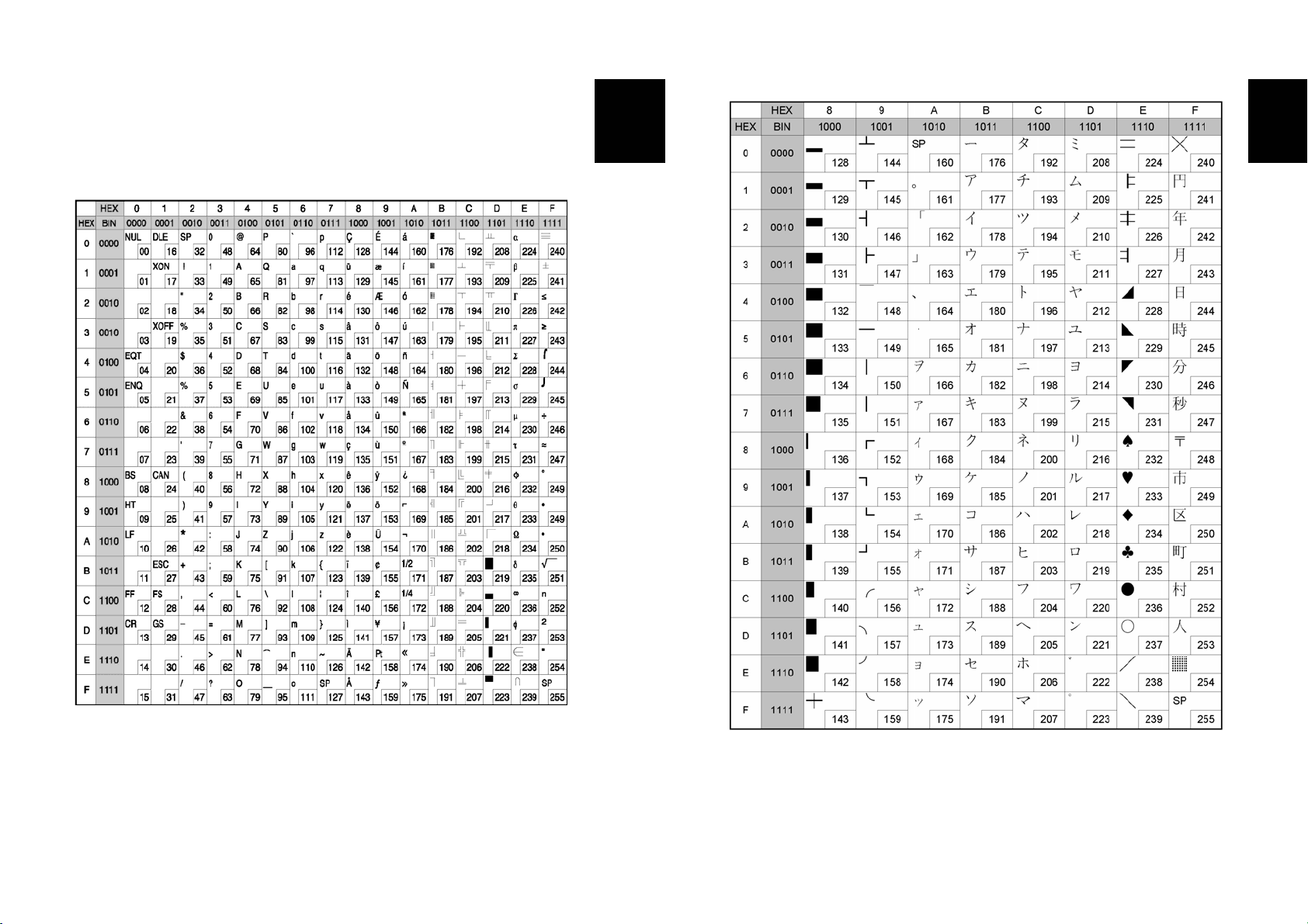
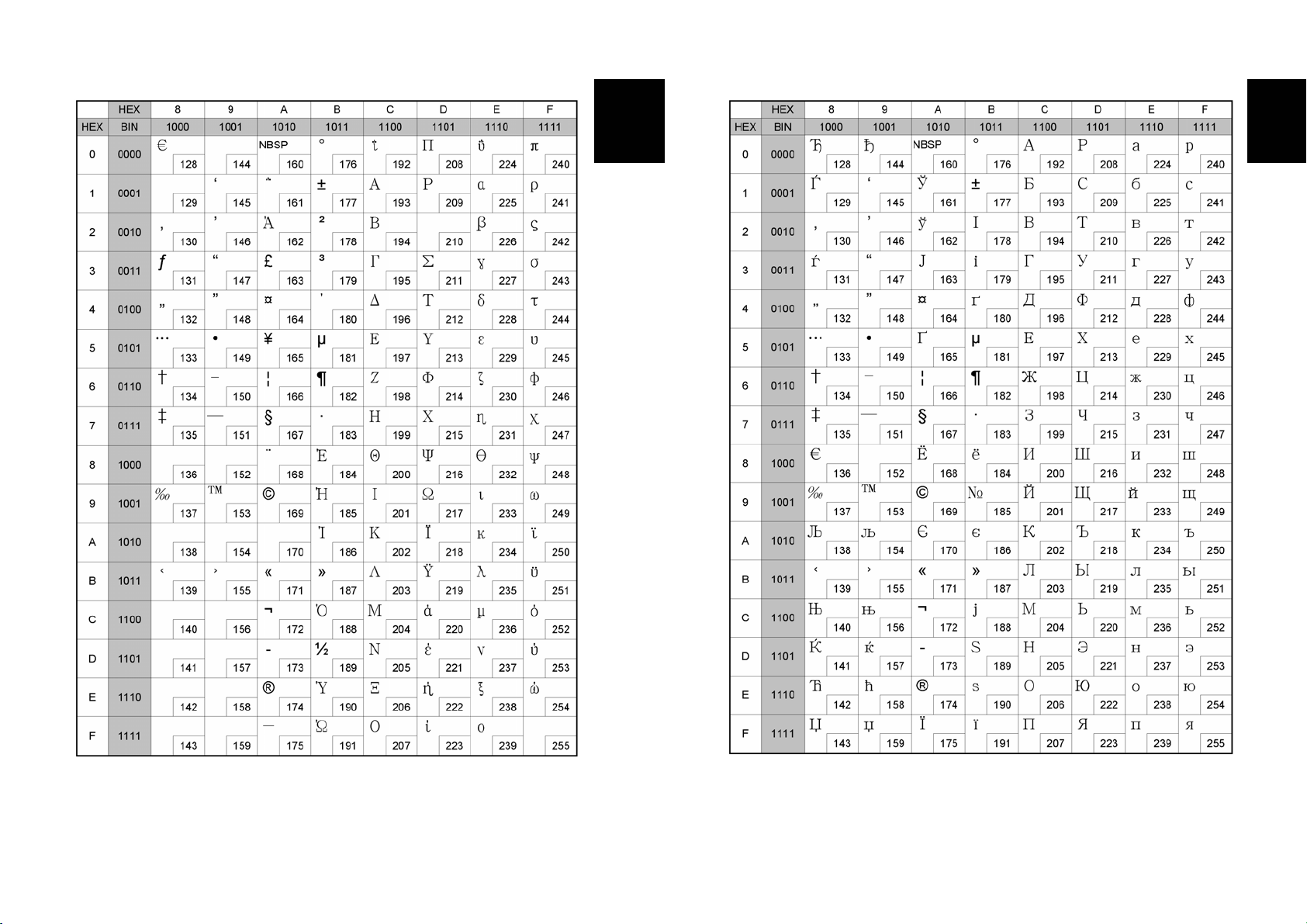
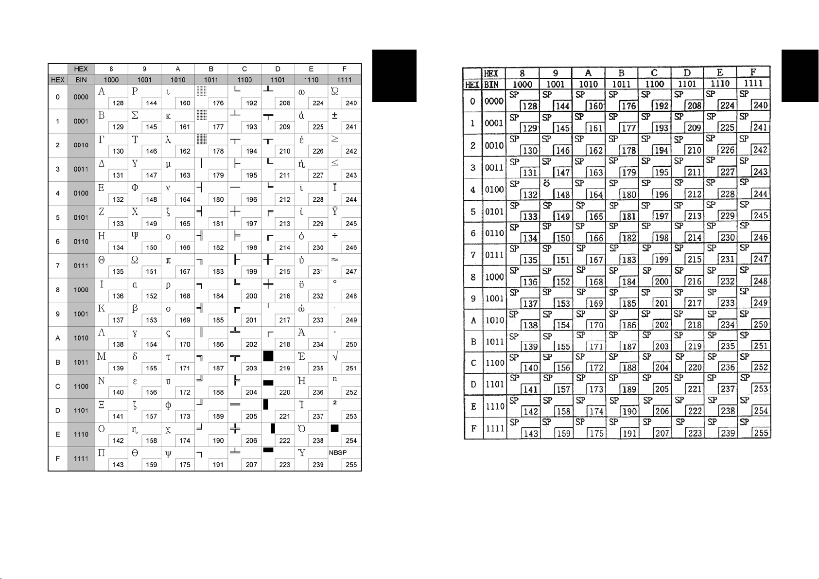
4장. 코드표
아래의 표는 문자 코드표 입니다. 헥사 숫자에 대응하는 문자를 찾기 위해서는 표의
상단부에서 오른쪽으로 그 다음에는 왼쪽의 숫자들을 아래쪽으로 문자를 찾습니다.
예) 4A = J
Korean
Korean
Page 0 ( PC437 : USA, Standard Europe)
( International Character Set : USA )
20
Page 1 ( Katakana )
21
Page 13
Korean
Korean
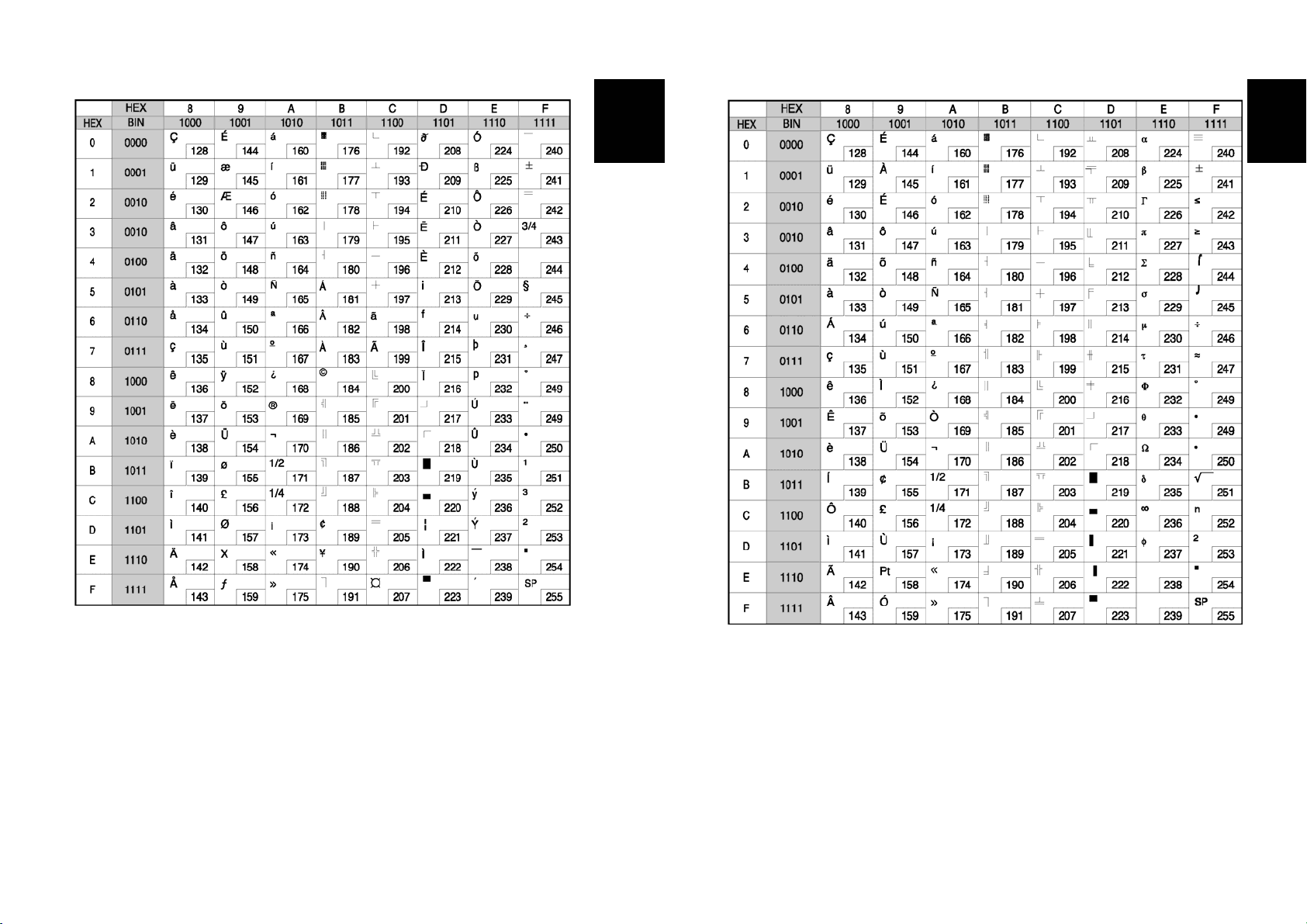
Page 2 ( PC850 : Multilingual )
22
Page 3 ( PC860 : Portuguese )
23
Page 14
Korean
Korean
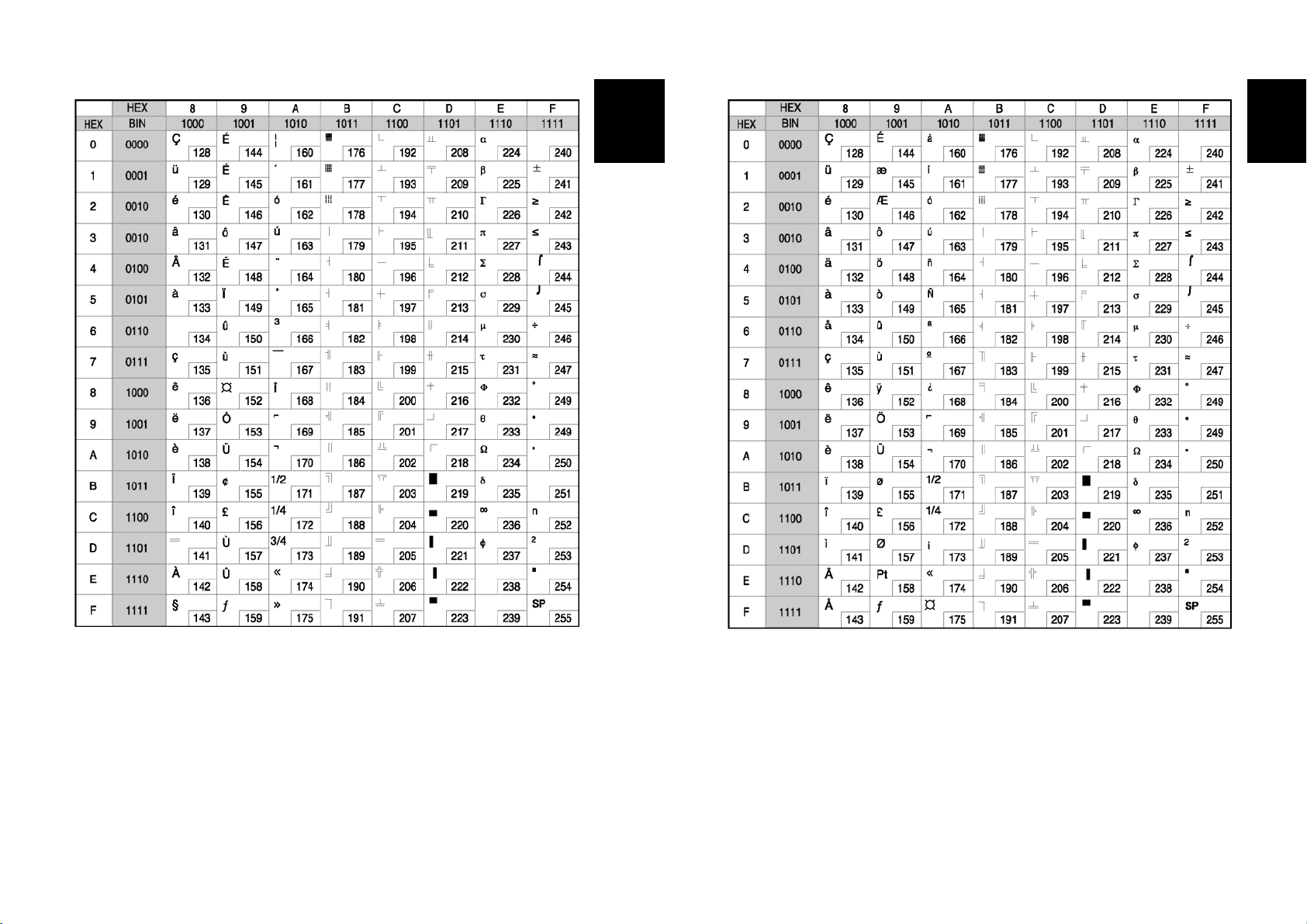
Page 4 ( PC 863 : Canadian - French )
24
Page 5 ( PC 865 : Nordic )
25
Page 15
Korean
Korean
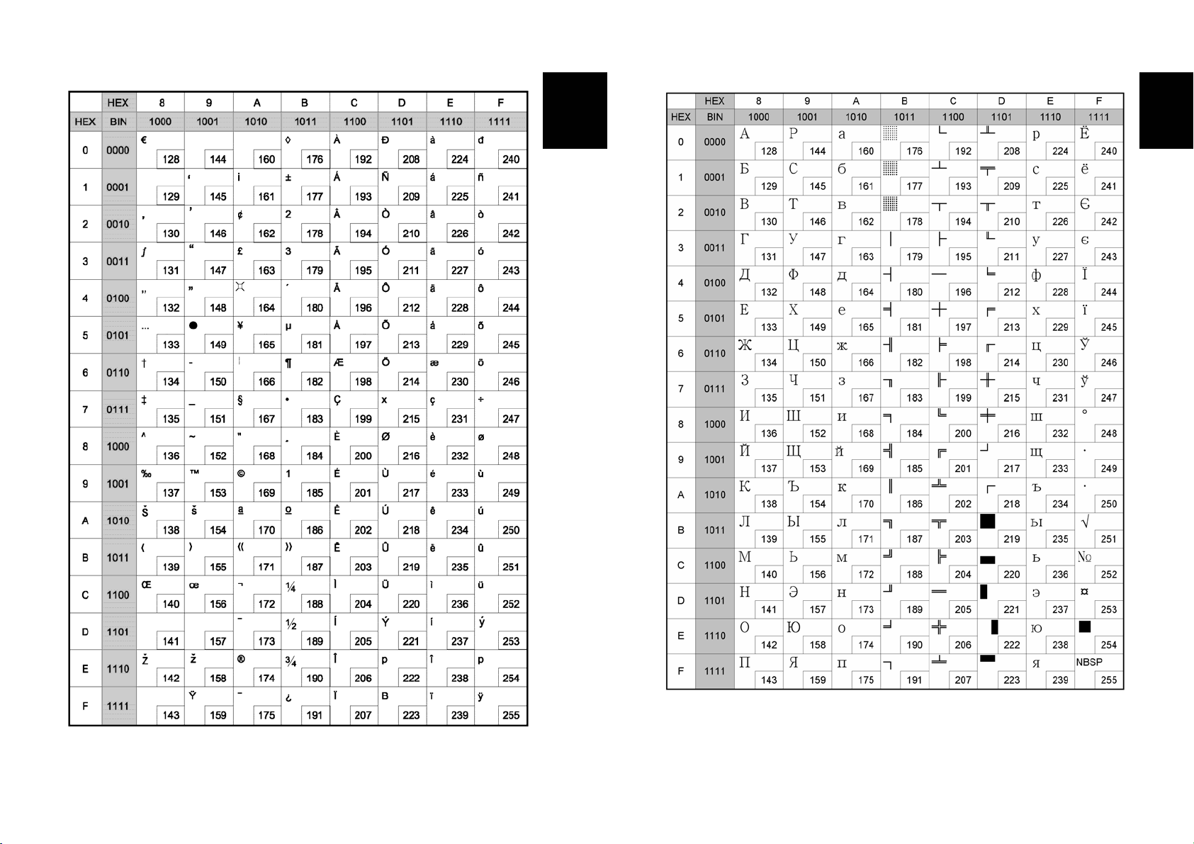
Page 16 ( WPC1252 : Latin 1 )
26
Page 17 ( PC866 : Cyrillic #2 )
27
Page 16

Korean
Korean
Page 18 ( PC852 : Latin2 )
28
Page 19 ( PC858 : Euro )
29
Page 17

Korean
Korean
Page 22 ( PC864 : Arabic )
30
Page 23 ( Thai character code 42 )
31
Page 18
Korean
Korean
Page 24 ( WPC1253 : Greek )
32
Page 28 ( WPC1251 : Cyrillic )
33
Page 19
Korean
Korean
Page 29 ( PC737 : Greek )
34
Page 255 ( Space Page )
35
Page 20
Korean
부록
Korean
A. 커넥터
POWER DK
ON
전원
커넥터
현금서랍
커넥터
RS-232
직렬케이블 커넥터
※ 시리얼 인터페이스 보드에 있는 딥 스위치를 "ON"
시켜주시면 DTR과 RTS 신호가 서로 연결됩니다.
SRP-370/372 커넥터
(직렬 인터페이스)
POWER DK
전원
커넥터
POWER DK
현금서랍
커넥터
SRP-370P/372P 커넥터
(병렬 인터페이스)
PARALLEL
병렬케이블 커넥터
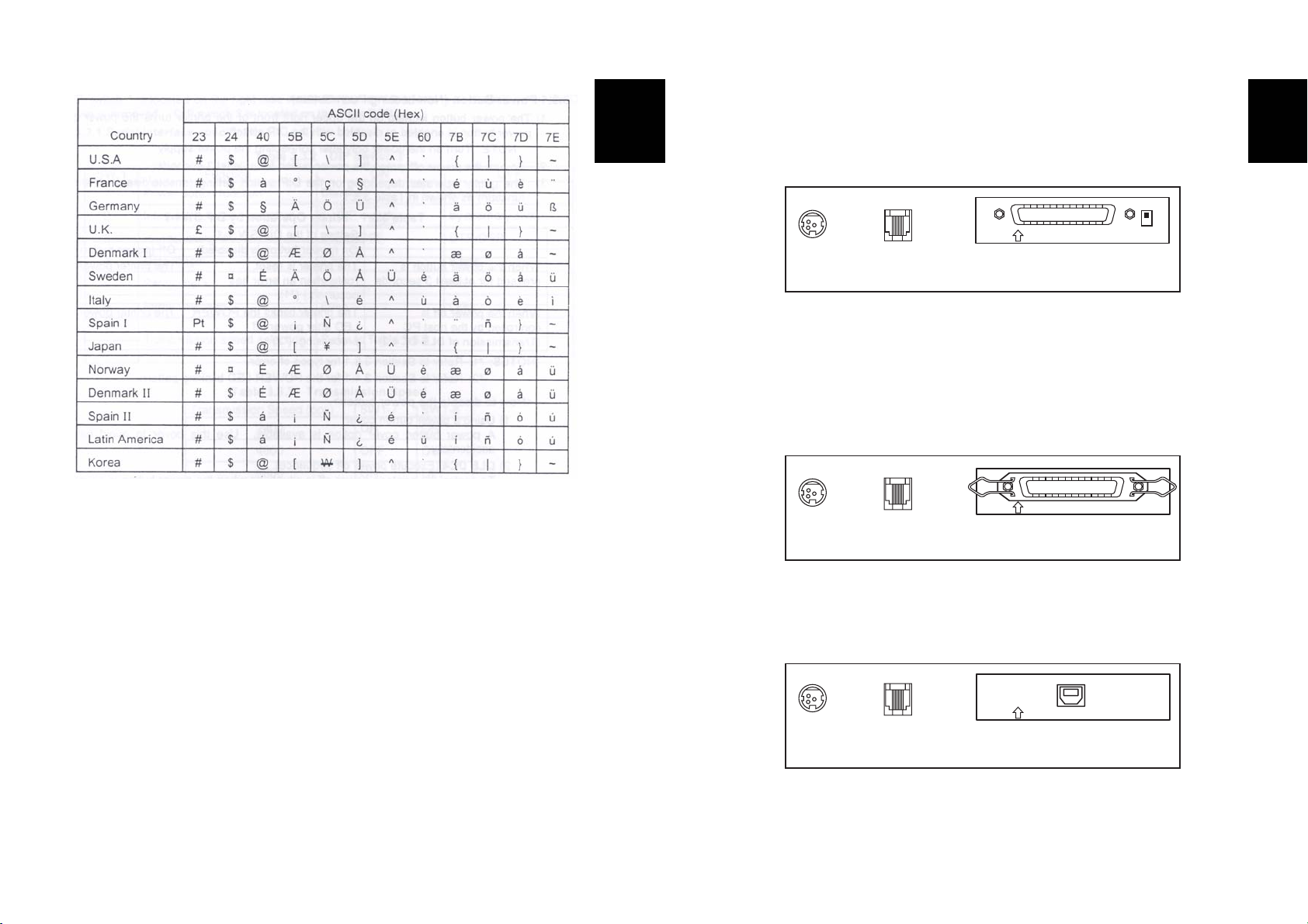
International Character Set
전원
커넥터
현금서랍
커넥터
SRP-370U/372U 커넥터
(USB 인터페이스)
USB
USB 커넥터
36
37
Page 21
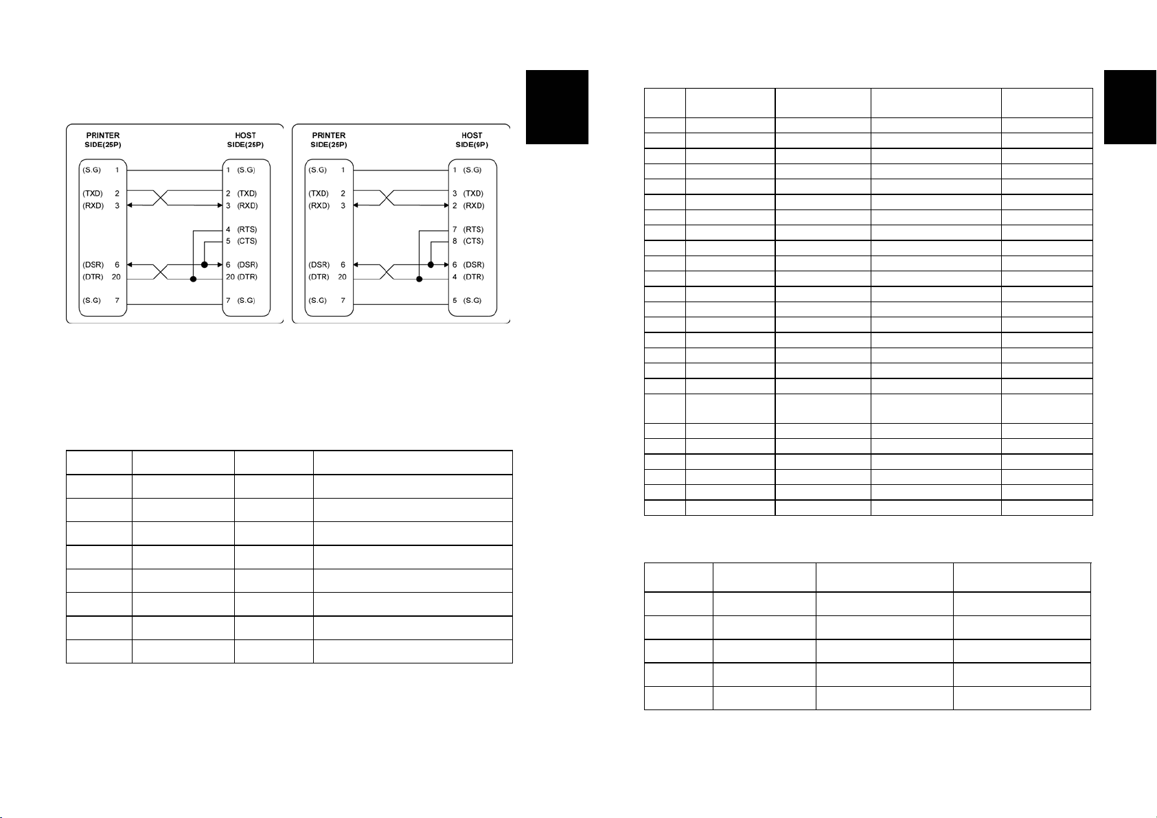
RS-232C 케이블 연결
인터페이스 커넥터
직렬 인터페이스 (RS-232)
핀 번호 신호명 방향 기 능
1 FG - 프레임 접지
2 TxD 출력 데이터 전송
3 RxD 입력 데이터 수신
4 RTS 출력 Ready To Send
5 CTS 입력 Clear to Ready
6 DSR 입력 Data Set Ready
7 SG - 신호 접지
20 DTR 출력 Data Terminal Ready
Korean
병렬 인터페이스 (IEEE-1284)
핀
번호
1 Host nStrobe HostClk HostClk
2 Host / Printer Data 0 (LSB) - Data 0 (LSB)
3 Host / Printer Data 1
4 Host / Printer Data 2 - Data 2
5 Host / Printer Data 3 - Data 3
6 Host / Printer Data 4 - Data 4
7 Host / Printer Data 5 - Data 5
8 Host / Printer Data 6 - Data 6
9 Host / Printer Data 7 (MSB) - Data 7 (MSB)
10 Printer nAck PtrClk PtrClk
11 Printer Busy PtrBusy /Data3,7 PtrBusy
12 Printer Perror AckDataReq/Data2,6 AckDataReq
13 Printer Select Xflag /Data1,5 Xflag
14 Host nAutoFd HostBusy HostBusy
15 NC NC NC
16 GND
17 FG FG FG
18 Printer Logic-H Logic-H Logic-H
19~
30
31 Host nInit nInit nInit
32 Printer nFault nDataAvail /Data0,4 nDataAvail
33 GND ND ND
34 Printer DK_Status ND ND
35 Printer +5V ND ND
36 Host nSelectIn 1284-Active 1284-Active
Source
GND
Compatibility
모드
니블 모드 바이트 모드
-
GND
GND
Data 1
GND
GND
USB 인터페이스
핀 번호 신호명 배선 (색) 기 능
Shell Shield Drain Wire 프레임 접지
1 VBUS 적색 호스트 전원
2 D- 백색 데이터 선(D-)
3 D+ 녹색 데이터 선(D+)
4 GND 흑색 신호 접지
Korean
38
39
Page 22
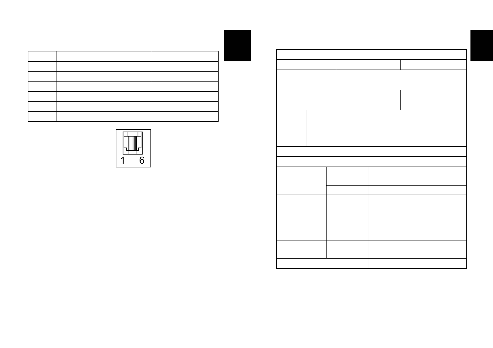
현금 서랍 커넥터
핀 번호 신호명 설명
1 프레임 접지 -
2 현금 서랍 열기 제어 신호 1 출력
3 현금 서랍 열기/닫기 수신 신호 입력
4 +24V -
5 현금 서랍 열기 제어 신호 2 출력
6 접지 신호 -
Korean
C. 사양
인쇄 방식
도트 농도
인쇄 폭
용지 폭
라인 당 문자 수
(기본값)
인쇄 속도
수신 버퍼 크기
열 전사 방식 (감열식) 인쇄
180 X 180 dpi (7dots/mm) 203 X 203 dpi (8dots/mm)
57.5mm, 72.192 ± 0.2mm
58mm,80mm,82.5 mm
180 DPI 42 (Font A)
56 (Font B)
180 DPI Mono : 47 lines/sec(1/6” Feed) 200mm/sec
Color : 23.6 Line/ Sec(1/6inch feed) 100mm/sec
203 DPI Mono : 42 lines/sec(1/6” Feed) 180mm/sec
Color : 21 Line/ Sec(1/6inch feed) 90mm/sec
4K Bytes
203 DPI 48 (Font A)
Korean
64 (Font B)
B. 프린터 청소
프린터 내부 용지에 먼지 등이 끼어있을 경우에는 인쇄품질이 저하될 수 있습니다.
이 경우 아래와 같은 방법으로 프린터를 청소하십시오.
1) 프린터 커버를 열고 용지가 끼워져 있다면 이를 제거하세요.
2) 알코올 용매제를 적신 천으로 프린터의 헤드 부분을 닦아 주세요.
3) 물을 적신 천으로 용지감지센서와 페이퍼롤러를 닦아주세요.
4) 용지를 삽입한 후 프린터 커버를 닫으세요.
용지감지센서에 의해 감지된 용지 잔량은 용지 중앙부분의 지름에 따라 다르게 나타날
수 있습니다. 용지감지센서를 제대로 설정하기 위해서는 구입하신 곳으로
문의하십시오.
참고 : 인쇄속도는 데이터전송속도와 명령어의 조합에 따라 다소 느려질 수 있습니다.
Supply voltage
Environmental
Conditions
수명 *
Auto Cutter *
* 이 값은 표준온도, 지정된 용지, 인쇄 레벨 2 상태에서 측정된 값입니다.
* 이 값은 온도, 인쇄 레벨에 따라 달라질 수 있습니다.
입력 전압 100~240 VAC
주 파 수 50/60 Hz
출력 전압 +24 VDC
온도
습도
메커니즘
0 ~ 45 ℃ (동작 시)
-10 ~ 50 ℃ (보관 시)
30 ~ 80 % RH (동작 시)
10 ~ 90 % RH (보관 시)
; 용지는 제외
Monochrome :70,000,000Lines
2Color :35,000,000Lines
1,200,000 Cut
40
41
Page 23
安全预防措施
在使用当前设备中,请遵守下列安全规程,以避免任何危险或材料破坏。
Chinese
警告
违反上述指令可能会导致严重损害或死亡。
不要将几个产品插入一个多孔电源插座
中。
• 这会导致过热和火灾。
• 如果插头潮湿或者肮脏,
请在使用前烘干或者擦拭。
• 如果插头与电源插座不配套,
请不要插上电源。
• 一定只使用标准化的多孔电源插座。
禁止
不要通过拉连接线的方式拔插头。
• 这可能会损坏连接线,
造成火灾或者打印机故障。
禁止
不要在手十分潮湿的时候,插或者拔电源
插头。
• 这可能发生触电。
禁止
不要用力弯曲连接线,或者将其置于重物
之下。
• 连接线损坏后,可能造成火灾。
禁止
您只能使用供应的适配器。
使用其它适配器十分危险。
仅使用供应的适配器
将塑料袋放在小孩拿不到的地方。.
否则,小孩们会将袋子套在头上。
禁止
如果发现打印机冒出不明原因的烟、气味
或者出现噪音,请拔下插头后,再采取应
急措施。
• 关闭打印机,拔下设备的插头。
• 在烟消失后,电话联系经销商进行维修。
拔下插头
打印机
Chinese
1
Page 24
警告
违反上述指令可能会导致严重损害或死亡。
将干燥剂放在小孩拿不到的地方。
• 不然,他们会把它们当作食物。
禁止
只使用批准的附件,自己不要尝试拆卸、
修理或者改装
如果需要这些服务,请电话联系经销商。
禁止拆卸
不要将水或者其他物品放进打印机中。
• 如果发生此类事件,
请关机并拔下打印机的插头,
然后,电话联系经销商。
。
打印机
将打印机安装在稳定的平面上。
• 如果打印机跌落,可能会遭到损坏,
且造成人员受伤。
禁止
不要用手触摸打印机的打印头。
这可能会烧伤手或者损坏打印质量。
打印机
打印头
禁止
失去控制时,不要使用打印机。这会导致
火灾或者触电。
请关机并拔下打印机的插头,
然后,电话联系经销商。.
Chinese
警告
静电会轻易地损坏某些半导体设备。在连接或者去掉打印机后面的电缆前,应该“关闭”打印
机,保护打印机免受静电的影响。如果打印机受到了静电的损坏,应该“关闭”打印机。
介绍
按照设计,SRP-370/372 卷纸打印机可与各种电子仪器一起使用,如系统 ECR、POS、银行设
备、计算机外围设备等等。
打印机的主要特性如下:
1. 高速打印:47(1/6”进纸)行/秒。
2. 低噪声热敏打印
3. RS-232、并行、USB
4. 数据缓冲器支持设备即使在打印期间也能接收打印数据。
5. 外围设备激励电路单元支持控制外部设备(如收银机抽屉)。
6. 字符最高可放大到原始大小的 64 倍。
7. 可以使用条形码命令打印条形码。
8. 使用 DIP 开关可选择不同的打印密度。
使用新的 SRP-370/372 打印机之前,请务必阅读本手册中的各种操作指导。
SRP-370/372.
注意:插座应该放在打印机附近,随手即可拿到。
Chinese
禁止
打印机
2
拔下插头
打印机经销商
3
Page 25

目录
第 1 章. 安装打印机 ......................................... 5
1-1. 打开包装 ............................................... 5
1-2.
连接电缆 ............................................... 6
1-3.
连接计算机 ............................................. 7
1-4.
连接抽屉 ............................................... 7
1-5.
连接电源 ............................................... 8
1-6.
安装或者更换纸卷 ....................................... 9
1-7.
调整和设置 ............................................ 11
1-8.
使用打印机 ............................................ 12
1-9.
设置 DIP 开关.......................................... 13
1-10.
设置内存开关 ......................................... 15
第 2 章 十六进制转储 ....................................... 17
第 3 章 自测 ............................................... 18
第 4 章 代码表 ............................................. 19
附录 ........................................................ 36
A. 连接器 .................................................. 36
B.
注意 .................................................... 39
C.
技术规范 ................................................ 40
Chinese
第 1 章. 安装打印机
1-1. 打开包装
打印机箱中应该包括下面插图中显示的各种物品。
如果任何物品出现了毁坏或丢失,请与您的经销商联系。
SRP-370/372 电缆盖
Chinese
4
卷纸 操作员手册 交流整流器 电源线
5
Page 26
1-2. 连接电缆
可将三根电缆连接到打印机上。再将所有电缆连接到打印机背后的连接板上,显示如下:
POWER DK
PARALLEL
电源
连接器
注意:在连接任何电缆前,确保已关闭了打印机和主机。
抽屉
推出连接器
接口连接器
Chinese
1-3. 连接计算机
您必需使用合适的接口电缆。
1. 将电缆连接器安全地插入打印机的接口连接器。
2. 拧紧电缆连接器两端的螺丝。
3. 将电缆的另一端连接到计算机上。
1-4. 连接抽屉
警告:
使用符合打印机技术规范的抽屉。使用不合适的抽屉,可能损坏抽屉和打印机。
小心
不要将电话线连接到抽屉推出连接器上,否则,可能损坏打印机和电话线。
将抽屉电缆插入紧挨着电源连接器的打印机背后的抽屉推出连接器上。
Chinese
6
7
Page 27
出
1-5. 连接电源
小心:
在连接或者断开打印机的电源时,确保电源没有插在插座上。否则,可能损坏电源或者打
印机。
如果电源的额定电压和您的插座电压不匹配,请联系您的经销商,寻求相关协助。不要插
上电源线。否则,可能损坏电源或者打印机。
1. 确保关闭了打印机的电源开关,且电源线已经从插座上拔下。
2. 检查电源上的标记,确保电源所需的电压符合插座的电压。
3. 按照下面图示插上电源。注意,插头的直边应该朝上。
Chinese
1-6. 安装或者更换纸卷
注意:一定要使用合乎规格的纸卷。不要使用纸张与纸芯胶粘在一起的纸卷,因为打印
机无法正常地检测到纸端。
1. 确保打印机此时没有接收数据;否则,可能会丢失数据。
2. 按下开盖按钮,打开纸卷盖。
注意:在打印机工作时,不要打开打印机机盖。这可能会损坏打印机。
3. 如果纸卷已经用完,请取下已经用过的纸卷芯。
4. 按照图示的方法插入纸卷。
Chinese
注意:
要取下直流电缆连接器之前,请确保电源线已经拔下,然后抓住箭头处的连接器并将其直接拉
8
9
Page 28

5. 一定注意纸卷出纸的方向要正确。
1-7. 调整和设置
6. 按照图示的方法拉出少量纸张。然后关闭机盖。
注意:在关闭机盖时,牢牢地按下打印机机盖的中心,以免纸张装载错误。
7. 按照图示的方法撕去纸端。
Chinese
Chinese
Power
Error
paper
Feed
1)本设备拥有两大特性:纸端和污点。如果要检测纸端。
必须将其定位在刻画的“a”位置,这是出厂默认设置。
如果要检测纸张上打印的污点,就必须将其移到“b”位置。
2)吸光度(Optical density,O.D)必须高于 0.6 的密度,以保障标准工作条件的安全。
注意,在标准状态下,纸张的污点密度可能较小。
3)O.D 值表(仅供参考)
P
o
w
e
r
E
r
r
o
r
p
a
p
e
r
F
e
e
d
1.4 0.9 0.6 0.3 0.2
10
11
Page 29

1-8. 使用打印机
控制面板
进纸
ESC C 5 命令可以禁用该按钮。
按下 FEED 按钮一次,则进纸一行。还可以按着 FEED 按钮不动,进行不断地进纸。
仪表板照明灯
电源
只要打印机打开,电源(POWER)指示灯就发光。
错误
显示错误。
纸张
这个指示灯表示快到纸卷末端。请安装新的纸卷,以便打印机继续打印。
在该指示灯闪烁时,表示处于打印自检备用状态,
或者使用宏执行命令时的宏执行备用状态。
Chinese
1-9. 设置 DIP 开关
串行接口(RS-232C、RS-485)技术规范
DIP 开关集 1 功能
开关编号。 功能 开 关 默认
SW1-1 关
SW1-2
SW1-3 - 握手 硬件 (DTR/DSR) 软件 (Xon/Xoff) 关
SW1-4 保存 -- 关
SW1-5 切纸器功能 禁用 启用 关
SW1-6 纸张 2 色 单色 关
SW1-7 保存 -- 关
SW1-8 保存 -- 关
波特率
*
选择
SW1-1 SW1-2 传输速度 备注
关 关 9600 Baud
开 关 19200 Baud
关 开 38400 Baud
开 开 115200 Baud 默认
DIP 开关集 2 功能
开关编号。 功能 开 关 默认
SW2-1 关
SW2-2 关
SW2-3
SW2-4 历史控制 启用 禁用 关
SW2-5 保存 -- 关
SW2-6 接口条件选择 按内存开关 按 DIP 开关 关
SW2-7 保存 -- 关
SW2-8 打印宽度 2” 打印 3” 打印 关
* 打印密度
SW 2-1 SW 2-2 SW 2-3 打印密度 备注
开 开 开 130%
关 开 开 120%
开 关 开 110%
关 关 开 105%
关 关 关 100% 默认
开 关 关 95%
关 开 关 90%
开 开 关 80%
波特率选择 * 参考下表
选择打印密度 * 参考下表
关
关
Chinese
12
13
Page 30

并行/ USB 接口规格
开关编号。 功能 开 关 默认
SW2-1 关
SW2-2 关
SW2-3
SW2-4 历史控制 启用 禁用 关
SW2-5 保存 -- 关
SW2-6 接口条件选择 按内存开关 按 DIP 开关 关
SW2-7 保存 -- 关
SW2-8 打印宽度 2” 打印 3” 打印 关
* 打印密度
SW 2-1 SW 2-2 SW 2-3 打印密度 备注
开 开 开 130%
关 开 开 120%
开 关 开 110%
关 关 开 105%
开 关 关 100% 默认
关 关 关 95%
关 开 关 90%
开 开 关 80%
※ 自动切纸器启用/禁用选择
SW 5 开 禁用自动切纸器
应用程序 忽略自动切纸器错误,继续打印。
选择打印密度 * 参考下表
DIP 开关集 1
关
Chinese
1-10. 设置内存开关
本打印机拥有“内存开关”集,它们是软件开关。内存开关集包括“MSW1”、“MSW2”、
“MSW 8”、“MSW9”、“定制值”、“串行通信条件”。
“内存开关设置实用程序”可以将内存开关集更改为开或关,如下表所示(默认:全部关闭):
注意:
内存开关的更改方法有三种:
- 内存开关设置实用程序
- 通过 ESC/POS 命令进行控制。
内存开关设置存储在 NV 内存中:因此,即使打印机已关闭,设置仍然存在。
MSW1
交换机 功能 开 关
1~4 保存 -- 固定为关闭
5 自动换行 启用 禁用
6~8 保存 -- 固定为关闭
MSW2
交换机 功能 开 关
1 字体选择 字体 B (9 x 24) 字体 A (12 x 24)
2 自动切纸器功能 全部切割 部分切割
3 保存 -- 固定为关闭
4~8 代码页选择 请参见下表
Chinese
14
15
Page 31

MSW2-8 MSW2-7 MSW2-6 MSW2-5 MSW2-4 字符表
关 关 关 关 关 第 437 页
关 关 关 关 开 第 1 页(片假名)
关 关 关 开 关 第 2,850 页
关 关 关 开 开 第 3,860 页
关 关 开 关 关 第 4,863 页
关 关 开 关 开 第 5,865 页
关 关 开 开 关 第 16 页 1252
关 关 开 开 开 第 17,866 页
关 开 关 关 关 第 18,852 页
关 开 关 关 开 第 19,858 页
关 开 关 开 关 保存
关 开 关 开 开 第 22,864 页
关 开 开 关 关 第 23 页 Thai42
关 开 开 关 开 第 24 页 1253
关 开 开 开 关
关 开 开 开 开
开 关 关 关 关
开 关 关 关 开 第 28 页 1251
开 关 关 开 关 第 29,737 页
开 关 关 开 开 保存
开 关 开 关 关 第 31 页 Thai16
开 关 开 关 开 保存
开 关 开 开 关 第 33 页 1255
开 关 开 开 开
开 开 关 关 关
开 开 关 关 开 第 36,855 页
开 开 关 开 关 第 37,857 页
MSW8
交换机 功能 开 关
1~8 保存 -- 固定为关闭
MSW9交换机 功能 开 关
1 保存 -- 固定为关闭
2 数据长度 7 位 8 位
3 奇偶校验选择 偶 奇
4 奇偶校验 启用 禁用
5 流控制 DTR/DSR XON/XOFF
6~8 波特率选择 请参见下表
MSW9-8 MSW9-7 MSW9-6 波特率
关 关 关 9600
关 关 开 19200
关 开 关 38400
关 开 开 57600
开 关 关 115200
保存
保存
Chinese
第 2 章 十六进制转储
本特性支持有经验的用户精确地查看传输到打印机中的数据内容。这在查找软件问题时十分有
用。在打开十六进制转储功能时,打印机会以十六进制格式打印全部的命令及其它数据,并打
印指南部分帮助您查找专用命令。
若要使用十六进制转储功能,请执行下列步骤:
1. 关闭打印机,然后打开机盖。
2. 打开打印机,同时按住 FEED 按钮。
3. 关闭机盖,然后,让打印机输入十六进制转储方式。
4. 运行任何向打印机发送数据的软件程序。打印机将以两栏格式打印接收的全部代码。第
一栏是十六进制代码,第二栏提供与这些代码相对应的 ASCII 字符。
0000: 1B 21 00 1B 26 02 40 40 ¦ . ! . . & . @ @
0008: 40 40 02 0D - 1B 44 0A 14 ¦ @ @ . . . D .
0010: 1E 28 28 28 - 00 01 0A 41 ¦ . ( ( ( . . . A
z (对于没有 ASCII 对应值的每个代码,会打印一个句点 (.)。)
z 在十六进制转储期间,禁用除 DLE EOT 和 DLE ENQ 外的所有命令。
5. 打印结束时,关闭打印机。
6. 打开打印机,然后关闭十六进制模式。
Chinese
16
17
Page 32

第 3 章 自测
打印自检目的是检查打印机是否存在问题。如果打印机运行不正常,请联系您的经销商。打印
自检会检查下列内容;
1. 确保纸卷的安装正常。
2. 打开电源,同时按住 FEED 按钮。开始打印自检。
3. 打印自检会打印出当前的打印机状态,包括控制 ROM 的版本和 DIP 开关设置。
4. 在打印了当前的打印机状态后,打印自检会打印下列内容并暂停(PAPER LED 指示灯会
闪烁)。
打印自检开始打印。
请按下 FEED 按钮
5. 按下 FEED 按钮,继续打印。打印机打印模式使用的是内置字符集。
6. 打印自检自动结束,并在打印下列内容后切纸。
* * * 已完成 * * *
打印机一旦完成打印自检,即可接收数据。
Chinese
第 4 章 代码表
下列页面显示的都是字符代码表。为了找到与十六进制数字相对应的字符,请在该表顶部找到
左边的数字,并在该表的左列向下查找右边的数字。例如,4A=J。
第 0 页(PC437:美国、标准欧洲
(国际字符集:美国))
Chinese
18
19
Page 33

Chinese
Chinese
第 1 页(片假名)
20
第 2 页(PC850:多语版)
21
Page 34

Chinese
Chinese
第 3 页(PC860:葡萄牙语)
22
第 4 页(PC863:加拿大-法语)
23
Page 35

Chinese
Chinese
第 5 页(PC863:北欧语)
24
第 16 页 (WPC1253:拉丁语 1)
25
Page 36

Chinese
Chinese
第 17 页(PC866:西里尔字母 #2)
26
第 18 页(PC852:拉丁语2)
27
Page 37

Chinese
Chinese
第 19 页(PC858:欧洲语言)
28
第 22 页(PC775:阿拉伯语)
29
Page 38

Chinese
Chinese
第 23 页(泰语字符码 42)
30
第 24 页 (WPC1253:希腊语)
31
Page 39

Chinese
Chinese
第 28 页 (WPC1253:西里尔字母)
32
第 29 页(PC737:希腊语)
33
Page 40

第 255 页(空白页)
Chinese
Chinese
(国际字符集)
34
35
Page 41

附录
A. 连接器
POWER DK
电源
连接器
※ 当串行接口板上的 DIP 开关是“ON”时,
DTR 和 RTS 会相互连接在一起。
POWER DK
电源
连接器
POWER DK
电源
连接器
抽屉推出
连接器
SRP-370/372 连接器
(串行接口)
抽屉推出
连接器
SRP-370P/372P 连接器
(并行接口)
抽屉推出
连接器
SRP-370U/372U 连接器
( USB 接口)
RS-232
接口连接器
PARALLEL
接口连接器
USB
USB 连接器
ON
RS-232C 电缆连接器
Chinese
Chinese
接口连接器
串行接口(RS-232)
插脚编号 信号名 方向 功能
1 FG - 机座接地
2 TxD 输出 发送数据
3 RxD 输入 接收数据
4 RTS 输出 准备发送
5 CTS 输入 清除发送
6 DSR 输入 数据集就绪
7 SG - 信号接地
20 DTR 输出 数据终端就绪
36
37
Page 42

信
并行接口(IEEE-1284)
插脚
编号
1 主机 nStrobe HostClk HostClk
2 主机/打印机 数据 0(LSB) - 数据 0(LSB)
3 主机/打印机 数据 1
4 主机/打印机 数据 2 - 数据 2
5 主机/打印机 数据 3 - 数据 3
6 主机/打印机 数据 4 - 数据 4
7 主机/打印机 数据 5 - 数据 5
8 主机/打印机 数据 6 - 数据 6
9 主机/打印机 数据 7(MSB) - 数据 7(MSB)
10 打印机 nAck PtrClk PtrClk
11 打印机 忙 PtrBusy /Data3,7 PtrBusy
12 打印机 Perror AckDataReq/Data2,6 AckDataReq
13 打印机 选择 Xflag /Data1,5 Xflag
14 主机 nAutoFd HostBusy HostBusy
15 NC NC NC
16 GND
17 FG FG FG
18 打印机 Logic-H Logic-H Logic-H
19~30 GND
31 主机 nInit nInit nInit
32 打印机 nFault nDataAvail /Data0,4 nDataAvail
33 GND ND ND
34 打印机 DK_Status ND ND
35 打印机 +5V ND ND
36 主机 nSelectIn 1284-Active 1284-Active
来源 兼容模式 四位模式 字节模式
-
GND
GND
数据 1
GND
GND
USB 接口
插脚编号
外壳 屏蔽 漏电引出线 机座接地
1 VBUS 红色 主机电源
2 D 白色 数据线(D-)
3 D 绿色 数据线(D+)
4 GND 黑色 信号接地
号名 分配(色) 功能
Chinese
抽屉连接器
插脚编号 信号名 方向
1 机座接地 -
2 抽屉推出驱动信号 1 输出
3 抽屉打开/关闭信号 输入
4 +24V -
5 抽屉推出驱动信号 2 输出
6 信号接地 -
B. 注意
打印机内部的不清洁可能会降低打印质量。在这种情况下,请按照
如下内容清理打印机。
1)打开打印机机盖,取出其中可能的纸张。
2)使用酒精溶剂棉拭,清理打印头。
3) 使用润湿的棉拭清理压纸卷轴滚筒和纸端传感器。
4)插入纸卷,关闭打印机机盖。
纸端传感器检测的纸张余量与纸芯的直径成正比。
若要调整该余量,请与当地的经销商联系。
Chinese
38
39
Page 43

g
C. 技术规范
打印方法
点密度
打印宽度
纸张宽度
每行字符数(默认)
打印速度
接收缓冲器大小
注意 :打印速度可能会降低,具体情况取决于数据传输速度和控制命令的组合情况。
电源电压
环境
条件
180 DPI 单色:47 行/秒(1/6” 进纸) 200毫米/秒
203 DPI 单色:42 行/秒(1/6” 进纸) 180毫米/秒
热敏行式打印
180 X 180 dpi (7点/毫米) 203 X 203 dpi (8点/毫米)
57.5毫米, 72.192 ± 0.2毫米
58毫米,80毫米,82.5 毫米
180 DPI 42 (字体 A)
56 (字体 B)
彩色23.6 行/秒(1/6” 进纸) 100毫米/秒
彩色21 行/秒(1/6” 进纸) 100毫米/秒
4k 字节
输入电压 100~240 VAC
频率 50/60 Hz
输出电压 +24 VDC
温度 0 ~ 45 ℃ (运行)
-10 ~ 50 ℃ (存储)
湿度 30 ~ 80 % RH (运行)
10 ~ 90 % RH (存储);纸张除外
203 DPI 48 (字体 A)
64 (字体 B)
Chinese
Chinese
En
lish
MCBF *
机械装置
自动切纸器寿命*
* 这些值是根据第 2 打印级别使用正常温度下建议使用的纸张计算
出来的。
* 这些值的具体数字可能会因为环境温度、
打印级别等等的变化而变化。
切割 1,200,000 次
单色:70,000,000 行
双色:35,000,000 行
40
41
Page 44

Safety Precautions
In using the present appliance, please keep the following safety
regulations in order to prevent any hazard or material damage.
WARNING
Violating following instructions can cause serious injury or death.
Do not plug several products in one
multi-outlet.
This can provoke over-heating and a fire.
If the plug is wet or dirty, dry or wipe it
before usage.
If the plug does not fit perfectly with the
outlet, do not plug in.
Be sure to use only standardized
multi-outlets.
PROHIBITED
Do not pull the cable to unplug.
This can damage the cable, which is the
origin of a fire or a breakdown of the printer.
PROHIBITED
Do not plug in or unplug with your hands
wet.
You can be electrocuted.
PROHIBITED
Do not bend the cable by force or leave it
under any heavy object.
A damaged cable can cause a fire.
PROHIBITED
You must use only the supplied adapter.
It is dangerous to use other adapters.
ONLY SUPPLIED ADAPTER
Keep the plastic bag out of children’s reach.
If not, a child may put the bag on his head.
PROHIBITED
If you observe a strange smoke, odor or
noise from the printer, unplug it before
taking following measures.
Switch off the printer and unplug the set
from the mains.
After the disappearance of the smoke, call
your dealer to repair it.
TO UNPLUG
PRINTER
English
WARNING
Violating following instructions can cause slight wound or damage the appliance.
Keep the desiccant out of children’s
reach.
If not, they may eat it.
PROHIBITED
Use only approved accessories and do
not try to disassemble, repair or remodel
it for yourself.
Call your dealer when you need these
services.
DISASSEMBLING
PROHIBITED
Do not let water or other foreign objects
in the printer.
printer before calling your dealer.
PROHIBITED
If this happened, switch off and unplug the
PRINER
PRINTER
Install the printer on the stable surface.
If the printer falls down, it can be broken
and you can hurt yourself.
PRINTER
PROHIBITED
Do not touch the HEAD of printer with
your hand.
This can burn your hand or deteriorate
printing quality.
HEAD
PROHIBITED
Do not use the printer when it is out of
order. This can cause a fire or an
electrocution.
Switch off and unplug the printer before
calling your dealer.
TO UNPLUG
PRINTER
DEALER
English
1
2
Page 45

Warning - U.S.
This equipment has been tested and found to comply with the limits for a Class A digital
device pursuant to Part 15 of the FCC Rules. These limits are designed to provide
reasonable protection against harmful interference when the equipment is operated in a
commercial environment. This equipment generates uses, and can radiate radio frequency
energy and, if not installed and used in accordance with the instruction manual, may cause
harmful interference to radio communications. Operation of this equipment in a residential
area is likely to cause harmful interference in which case the user will be required to
correct the interference at his own expense.
Notice - Canada
This Apparatus complies with class “A” limits for radio interference as specified in the
Canadian department of communications radio interference regulations.
Get appareil est conforme aux normes class “A” d’interference radio tel que specifier par
ministre canadien des communications dans les reglements d’interference radio.
Caution
Some semiconductor devices are easily damaged by static electricity. You should turn the
printer “OFF”, before you connect or remove the cables on the rear side, in order to guard
the printer against the static electricity. If the printer is damaged by the static electricity,
you should turn the printer “OFF”.
INTRODUCTION
The SRP-370/372 Roll Printer are designed for use with electronic instruments such as
system ECR, POS, banking equipment, computer peripheral equipment, etc.
The main features of the printer are as follows:
Please be sure to read the instruction in this manual carefully before using your new
SRP-370/372.
NOTE : The socket-outlet shall be near the equipment and it
shall be easy accessible.
1. High speed printing : 47(1/6” Feed) lines per second.
2. Low noise thermal printing.
3. RS-232, Parallel, USB
4. The data buffer allows the unit to receive print data even during printing.
5. Peripheral units drive circuit enables control of external devices such as
cash drawer.
6. Characters can be scaled up to 64 times compared to it’s original size.
7. Bar code printing is possible by using a bar code command.
8. Different print densities can be selected by DIP switches.
All specifications are subjected to change※
without notice.
English
Table of Contents
CHAPTER 1. SETTING UP THE PRINTER ..................................... 5
UNPACKING .............................................................................. 5
1-1.
CONNECTING THE CABLES ............................................................. 6
1-2.
CONNECTING THE COMPUTER ......................................................... 7
1-3.
CONNECTING THE DRAWER ........................................................... 7
1-4.
CONNECTING THE POWER SUPPLY ................................................... 8
1-5.
INSTALLING OR REPLACING THE PAPER ROLL...................................... 9
1-6.
ADJUSTMENTS AND SETTINGS ...................................................... 11
1-7.
USING THE PRINTER.................................................................. 12
1-8.
SETTING THE DIP SWITCHES ........................................................ 13
1-9.
SETTING THE MEMORY SWITCHES................................................ 15
1-10.
CHAPTER 2. HEXADECIMAL DUMPING ..................................... 17
CHAPTER 3. THE SELF TEST ...................................................... 18
CHAPTER 4. CODE TABLE.......................................................... 19
CHAPTER 5. CONTROL COMMANDS LIST.................................. 36
APPENDIX ................................................................................. 84
CONNECTORS ............................................................................. 84
A.
NOTES ..................................................................................... 87
B.
SPECIFICATION ........................................................................... 88
C.
English
3
4
Page 46

Chapter 1. Setting Up the Printer
1-1. Unpacking
Your printer box should include these items. If any items are damaged or missing,
please contact your dealer for assistance.
SRP-370/372 Cover Cable
Roll Paper Operator’s manual AC Adapter Power Code
English
1-2. Connecting the Cables
You can connect up the three cables to the printer. They all connect to the connector
panel on the back of the printer, which is shown below:
POWER DK
PARALLEL
Power
Supply
Notes : Before connecting any of the cables, make sure that both the printer and the
host are turned off.
Drawer
Kick-out
Interface Connector
English
5
6
Page 47

1-3. Connecting the computer
You need an appropriate interface cable.
1. Plug the cable connector securely into the printer’s interface connector.
2. Tighten the screws on both sides of the cable connector.
3. Attach the other end of the cable to the computer.
1-4. Connecting the Drawer
WARNING:
Use a drawer that matches the printer specification. Using an improper drawer may
damage the drawer as well as the printer.
CAUTION:
Do not connect a telephone line to the drawer kick-out connector; otherwise the
printer and the telephone line may be damaged.
Plug the drawer cable into the drawer kick-out connector on the back of the printer
next to the power supply connector.
English
1-5. Connecting the Power Supply
CAUTIONS:
When connecting or disconnecting the power supply from the printer, make sure that
the power supply is not plugged into an electrical outlet. Otherwise you may damage
the power supply or the printer.
If the power supply’s rated voltage and your outlet’s voltage do not match, contact
your dealer for assistance. Do not plug in the power cord. Otherwise, you may damage
the power supply or the printer.
1. Make sure that the printer’s power switch is turned off, and the power supply’s
power cord is unplugged from the electrical outlet.
2. Check the label on the power supply to make sure that the voltage required by the
power supply matches that of your electrical outlet.
3. Plug in the power supply’s cable as shown below. Notice that the flat side of the
plug faces up.
English
Notes : To remove the DC cable connector, make sure that the power supply’s power
cord is unplugged; then grasp the connector at the arrow and pull it straight out.
7
8
Page 48

pap
g
1-6. Installing or Replacing the Paper Roll
Notes : Be sure to use paper rolls that meet the specifications. Do not use paper rolls
that have the paper glued to the core because the printer cannot detect the
paper end correctly.
5. Be sure to note the correct direction that the paper comes off the roll.
1. Make sure that the printer is not receiving data; otherwise, data may be lost.
2. Open the paper roll cover by pressing the cover-open button.
Notes : Do not open the print cover while the printer is operating.
This may damage the printer.
3. Remove the used paper roll core if there is one.
4. Insert the paper roll as shown.
English
6. Pull out a small amount of paper, as shown. Then close the cover.
P
o
w
e
r
E
r
r
o
r
p
a
p
e
r
F
e
e
d
Notes : When closing the cover, press the center of printer cover firmly to prevent
er miss-loadin
7. Tear off the paper as shown.
English
Power
Error
paper
Feed
9
10
Page 49

1-7. Adjustments and Settings
1)It has 2 features ; Paper end and Black mark. For detecting Paper End,
it must be positioned at “a” Position in drawing and it is a factory default setting.
For detecting Black mark printed on the paper, it must be moved to “b” position.
2) Optical density (O.D) must be higher than 0.6 in density to secure a standard working
condition.
Make sure if the density of paper black mark is lesser it might be a cause of normality.
3) Table of O.D value (Reference)
1.4 0.9 0.6 0.3 0.2
English
1-8. Using the Printer
Control Panel
Button
The button can be disabled by the ESC c 5 command.
Press the FEED button once to advance paper one line. You can also hold down the
FEED button to feed paper continuously.
Panel lights
POWER
The POWER light is on whenever the printer is on.
ERROR
This indicates an error.
PAPER OUT
This light indicates the near end of the paper roll. Install a new paper roll and the
printer Will continue printing.
When the light blinks, it indicates the self-test printing standby state or macro
execution Standby state when the macro execution command is used.
English
11
12
Page 50

1-9. Setting the DIP Switches
Serial Interface(RS-232C, RS-485) Specification
DIP Switch Set 1 Functions
Switch No. Function ON OFF Default
SW1-1 OFF
SW1-2
SW1-3 Handshaking
SW1-4 Reserved -- OFF
SW1-5 Cutter Function Disable Enable OFF
SW1-6 Paper 2 Color Mono OFF
SW1-7 Reserved -- OFF
SW1-8 Reserved -- ON
* Baud rate selection
SW1-1 SW1-2 Trans- Speed Remark
OFF OFF 9600 Baud
ON OFF 19200 Baud
OFF ON 38400 Baud
ON ON 115200 Baud Default
Dip Switch Set 2 Functions
Switch No. Function ON OFF Default
SW2-1 OFF
SW2-2 OFF
SW2-3
SW2-4 Historical Control Enable Disable OFF
SW2-5 Reserved -- OFF
SW2-6
SW2-7 Reserved -- OFF
SW2-8 Printing width 2” Printing 3” Printing OFF
* Print Density
SW 2-1 SW 2-2 SW 2-3 Print Density Remark
ON ON ON 130%
OFF ON ON 120%
ON OFF ON 110%
OFF OFF ON 105%
OFF OFF OFF 100% Default
ON OFF OFF 95%
OFF ON OFF 90%
ON ON OFF 80%
Baud Rate Selection * Refer to below Table
Hardware
(DTR/DSR)
Select Print Density * Refer to below Table
Interface Condition
Selection
by Memory
Switch
Software
(Xon/Xoff)
by DIP
Switch
OFF
OFF
OFF
OFF
English
Parallel/USB Interface Specification
Switch No. Function ON OFF Default
SW2-1 OFF
SW2-2 OFF
SW2-3
SW2-4 Historical Control Enable Disable OFF
SW2-5 Reserved -- OFF
SW2-6
SW2-7 Reserved -- OFF
SW2-8 Printing width 2” Printing 3” Printing OFF
* Print Density
SW 2-1 SW 2-2 SW 2-3 Print Density Remark
ON ON ON 130%
OFF ON ON 120%
ON OFF ON 110%
OFF OFF ON 105%
ON OFF OFF 100% Default
OFF OFF OFF 95%
OFF ON OFF 90%
ON ON OFF 80%
※ Auto Cutter Enable / Disable selection
SW 5 ON Auto Cutter Disabled
Application Ignores Auto Cutter error for continuous printing.
Select Print Density * Refer to below Table
Interface Condition
Selection
Dip Switch Set 1
by Memory
Switch
by DIP
Switch
OFF
OFF
English
13
14
Page 51

1-10. Setting the Memory Switches
This printer has “Memory Switch” set which is software switches. Memory Switch set has
“MSW1”, “MSW2”, “MSW8”, “MSW9” “Customize value”, “Serial communication condition”.
“Memory Switch setting utility” can change the Memory Switch set to ON or OFF as shown
in the table below (default : all OFF) :
Notes : The Memory Switch is available to be changed by three methods :
- Memory Switch setting utility.
- Control from ESC/POS command.
Settings of the Memory Switch are stored in the NV memory : therefore, even if the printer
is turned off, the settings are maintained.
MSW1
Switch Function ON OFF
1~4 Reserved -- Fixed to OFF
5 Auto Line Feed Enable Disable
6~8 Reserved -- Fixed to OFF
MSW2
Switch Function ON OFF
1 Font Selection Font B (9 x 24) Font A (12 x 24)
2 Auto Cutter Function Full Cutting Partial Cutting
3 Reserved -- Fixed to OFF
4~8 Code Page Selection Refer to following Table
English
MSW2-8 MSW2-7 MSW2-6 MSW2-5 MSW2-4 Character Table
OFF OFF OFF OFF OFF Page 0 437
OFF OFF OFF OFF ON Page 1 Katakana
OFF OFF OFF ON OFF Page 2 850
OFF OFF OFF ON ON Page 3 860
OFF OFF ON OFF OFF Page 4 863
OFF OFF ON OFF ON Page 5 865
OFF OFF ON ON OFF Page 16 1252
OFF OFF ON ON ON Page 17 866
OFF ON OFF OFF OFF Page 18 852
OFF ON OFF OFF ON Page 19 858
OFF ON OFF ON OFF Reserved
OFF ON OFF ON ON Page 22 864
OFF ON ON OFF OFF Page 23 Thai42
OFF ON ON OFF ON Page 24 1253
OFF ON ON ON OFF
OFF ON ON ON ON
ON OFF OFF OFF OFF
ON OFF OFF OFF ON Page 28 1251
ON OFF OFF ON OFF Page 29 737
ON OFF OFF ON ON Reserved
ON OFF ON OFF OFF Page 31 Thai16
ON OFF ON OFF ON Reserved
ON OFF ON ON OFF Page 33 1255
ON OFF ON ON ON
ON ON OFF OFF OFF
ON ON OFF OFF ON Page 36 855
ON ON OFF ON OFF Page 37 857
Reserved
Reserved
MSW8
Switch Function ON OFF
1~8 Reserved -- Fixed to OFF
MSW9
Switch Function ON OFF
1 Reserved -- Fixed to OFF
2 Data Length 7 Bits 8 Bits
3 Parity Selection Even Odd
4 Parity Check Enable Disable
5 Flow Control DTR/DSR XON/XOFF
6~8 Baud Rate Selection Refer to following Table
MSW9-8 MSW9-7 MSW9-6 Baud Rate
OFF OFF OFF 9600
OFF OFF ON 19200
OFF ON OFF 38400
OFF ON ON 57600
ON OFF OFF 115200
English
15
16
Page 52

Chapter 2. Hexadecimal Dumping
This feature allows experienced users to see exactly what data is coming to the printer.
This can be useful in finding software problems. When you turn on the hexadecimal dump
function, the printer prints all commands and data in hexadecimal format along with a
guide section to help you find specific commands.
To use the hexadecimal dump function, follow these steps:
1. After you make sure that the printer is off, open the cover.
2. Turn on the printer, while holding down the FEED button.
3. Close the cover, then the printer enters the hexadecimal dump mode.
4. Run any software program that sends data to the printer. The printer will print all the
codes it receives in a two-column format. The first column contains the hexadecimal
codes and the second column gives the ASCII characters that corresponds to the
codes.
0000: 1B 21 00 1B - 26 02 40 40 ¦ . ! . . & . @ @
0008: 40 40 02 0D - 1B 44 0A 14 ¦ @ @ . . . D . .
0010: 1E 28 28 28 - 00 01 0A 41 ¦ . ( ( ( . . . A
z A period (.) is printed for each code that has no ASCII equivalent.
z During the hex dump, all commands except DLE EOT and DLE ENQ are
disabled.
5. When the printing finishes, turn off the printer.
6. Turn on the printer and then the hexadecimal mode is off.
English
Chapter 3. The self test
The self-test checks whether the printer has any problems. If the printer does not function
properly, contact your dealer. The self-test checks the following;
1. Make sure paper roll has been installed properly.
2. Turn on the power while holding down the FEED button. The self-test begins.
3. The self-test prints the current printer status, which provides the control ROM version
and the DIP switch setting.
4. After printing the current printer status, self-test printing will print the following, and
pause (The PAPER LED light blinks).
Self-test printing.
Please press the FEED button
5. Press the FEED button to continue printing. The printer prints a pattern using the
built-in character set.
6. The self-test automatically ends and cuts the paper after printing the following.
*** COMPLETED ***
The printer is ready to receive data as soon as it completes the self-test.
English
17
18
Page 53

Chapter 4. Code Table
The following pages show the character code tables. To find the character corresponding
to a hexadecimal number, count across the top of the table for the left digit and count
down the left column of the table for the right digit. For example, 4A = J.
Page 0 ( PC437 : USA, Standard Europe)
( International Character Set : USA )
English
English
Page 1 ( Katakana )
19
20
Page 54

English
Page 2 ( PC850 : Multilingual )
Page 3 ( PC860 : Portuguese )
English
21
22
Page 55

English
Page 4 ( PC 863 : Canadian - French )
Page 5 ( PC 865 : Nordic )
English
23
24
Page 56

Page 16 ( WPC1252 : Latin 1 )
English
English
Page 17 ( PC866 : Cyrillic #2 )
25
26
Page 57

English
Page 18 ( PC852 : Latin2 )
Page 19 ( PC858 : Euro )
English
27
28
Page 58

English
Page 22 ( PC864 : Arabic )
Page 23 ( Thai character code 42 )
English
29
30
Page 59

English
Page 24 ( WPC1253 : Greek )
Page 28 ( WPC1251 : Cyrillic )
English
31
32
Page 60

English
Page 29 ( PC737 : Greek )
Page 255 ( Space Page )
English
33
34
Page 61

Chapter 5. Control Commands List
Command Name
HT Horizontal tab
LF Print and line feed
FF Print and return to standard mode (in page mode)
CR Print and carriage return
CAN Cancel print data in page mode
DLE EOT Real-time status transmission
DLE ENQ Real-time request to printer
DLE DC4
ESC FF Print data in page mode
ESC SP Set right-side character spacing
ESC ! Select print mode(s)
ESC $ Set absolute print position
ESC % Select/cancel user-defined character set
ESC & Define user-defined characters
English
ESC * Select bit-image mode
ESC - Turn underline mode on/off
ESC 2 Select default line spacing
ESC 3 Set line spacing
ESC = Select peripheral device
ESC ? Cancel user-defined characters
ESC @ Initialize printer
ESC D Set horizontal tab positions
ESC E Turn emphasized mode on/off
ESC G Turn double-strike mode on/off
ESC J Print and feed paper
ESC L Select page mode
ESC M Select character font
ESC R Select an international character set
ESC S Select standard mode
ESC T Select print direction in page mode
ESC V Turn 90° clockwise rotation mode on/off
ESC W Set printing area in page mode
ESC \
ESC a Select justification
ESC c 3 Select paper sensor(s) to output paper-end signals
ESC c 4 Select paper sensor(s) to stop printing
ESC c 5 Enable/disable panel buttons
International Character Set
Generate pulse in real-time
Execute power-off sequence
Clear buffer(s)
English
Set relative print position
35
36
Page 62

Command Name
ESC d Print and feed n lines
ESC p General pulse
ESC t Select character code table
ESC { Turn upside-down printing mode on/off
FS p print NV bit image
FS q Define NV bit image
GS ! Select character size
GS $ Set absolute vertical print position in page mode
GS ( A Execute test print
GS ( D Enable/disable real-time command
GS ( E User setup commands
GS 8 L
GS ( L
GS ( M Customize printer control value(s)
GS ( N Select character style(s)
GS * Define downloaded bit image
GS / Print downloaded bit image
GS : Start/end macro definition
GS B Turn white/black reverse printing mode on/off
GS H Select printing position of HRI characters
GS I Transmit printer ID
GS L Set left margin
GS P Set horizontal and vertical motion units
GS T Set print position to the beginning of print line
GS V Select cut mode and cut paper
GS W Set printing area width
GS \
GS ^ Execute macro
GS a Enable/disable Automatic Status Back (ASB)
GS b Turn smoothing mode on/off
GS f Select font for HIR characters
GS h Set bar code height
GS k Print bar code
GS r Transmit status
GS v 0 Print raster bit image
GS w Set bar code width
Set graphics data
Set relative vertical print position in page mode
English
Command Notation
[Name]
[Format]
[Range]
[Description]
The name of the command.
The code sequence. ASCII Indicates the ASCII equivalents.
Hex indicates the hexadecimal equivalents.
Decimal indicates the decimal equivalents.
[ ] k indicates the contents of the [ ] should be repeated k times.
Gives the allowable ranges for the arguments.
Describes the function of the command.
Explanation of Terms
LSB Least Significant Bit
HT
[Name]
[Format]
[Description]
LF
[Name]
[Format]
[Description]
FF
[Name]
[Format]
[Description]
Horizontal tab.
ASCII HT
Hex 09
Decimal 9
▪ Moves the print position to the next horizontal tab position.
Print and line feed.
ASCII LF
Hex 0A
Decimal 10
▪ In standard mode, prints the data in the print buffer and feeds one line
based on the current line spacing.
▪ In page mode, modes the print position in memory to feed one line based
on the current line spacing.
Print and return to standard mode in page mode.
ASCII FF
Hex 0C
Decimal 12
▪ In page mode, prints the data in the print buffer collectively and returns
to standard mode.
English
37
38
Page 63

CR
[Name]
[Format]
[Description]
[Notes]
CAN
[Name]
[Format]
[Description]
DLE EOT n
[Name]
[Format]
[Range]
[Description]
n Function
1 Transmit printer status.
2 Transmit off-line status.
3 Transmit error status.
4 Transmit paper roll sensor status.
▪ This printer transmits the following status in real time.
Print and carriage return.
ASCII CR
Hex 0D
Decimal 13
▪ When automatic line feed is enabled, this command functions the same as
LF.
▪ When automatic line feed is disabled, this command is ignored CR.
▪ The automatic line feed is ignored with a serial interface model.
▪ With a parallel interface model, the automatic line feed is set with
memory switch 1-5 when the printer power is turned on or reset.
Cancel print data in page mode.
ASCII CAN
Hex 18
Decimal 24
▪ In page mode, deletes all the print data in the current printable area.
Transmission real-time status.
ASCII DLE EOT n
Hex 10 04 n
Decimal 16 4 n
1 ≤ n ≤ 4
▪ Transmits the status specified by n in real-time as follows:
English
Bit Off/On Hex Decimal Function
0 Off 00 0 Fixed.
1 On 02 2 Fixed.
Off 00 0 Drawer kick-out connector pin 3 is LOW. 2
On 04 4 Drawer kick-out connector pin 3 is HIGH.
Off 00 0 On-Line. 3
On 08 8 Off-Line.
4 On 10 16 Fixed.
Off 00 0 Not in on-line waiting status. 5
On 20 32 During on lines waiting status.
Off 00 0 Paper FEED button is turned Off. 6
On 40 64 Paper FEED button is turned On.
7 Off 00 0 Fixed.
Bit Off/On Hex Decimal Function
0 Off 00 0 Fixed.
1 On 02 2 Fixed.
Off 00 0 Cover is closed. 2
On 04 4 Cover is open.
Off 00 0 Paper is not being fed by using the paper FEED button. 3
On 08 8 Paper is being fed by the paper FEED button.
4 On 10 16 Fixed.
Off 00 0 No paper-end stop. 5
On 20 32 Printing is being stopped.
Off 00 0 No error. 6
On 40 64 Error has occurred.
7 Off 00 0 Fixed.
Bit Off/On Hex Decimal Function
0 Off 00 0 Fixed.
1 On 02 2 Fixed.
Off 00 0 No mechanical error. 2
On 04 4 Mechanical error has occurred.
Off 00 0 No auto-cutter error. 3
On 08 8 Auto-cutter error occurred.
4 On 10 16 Fixed.
Off 00 0 No unrecoverable error. 5
On 20 32 Unrecoverable error has occurred.
Off 00 0 No automatically recoverable error. 6
On 40 64 Automatically recoverable error has occurred.
7 Off 00 0 Fixed.
n=1 : Printer status
n=2 : Off-line status
English
n=3 : Error status
39
40
Page 64

n=4 : Continuous paper sensor status
Bit Off/On Hex Decimal Function
0 Off 00 0 Fixed.
1 On 02 2 Fixed.
Off 00 0 Paper roll near-end sensor : paper adequate. 2
On 04 4 Paper roll near-end sensor : paper near end.
Off 00 0 Paper roll near-end sensor : paper adequate. 3
On 08 8 Paper roll near-end sensor : paper near end.
4 On 10 16 Fixed.
Off 00 0 Paper roll near-end sensor : paper present. 5
On 20 32 Paper roll near-end sensor : paper not present.
Off 00 0 Paper roll near-end sensor : paper present. 6
On 40 64 Paper roll near-end sensor : paper not present.
7 Off 00 0 Fixed.
[Notes] ▪ If print data includes a character string with this command, the printer
DLE ENQ n
[Name]
[Format]
[Range]
[Description]
n Request
0 Works the same as when the paper FEED button is pressed once during waiting
1
2 Recovers from an error after clearing the receive and print buffers.
[Notes] ▪ Specify n=1 or 2 after removing the cause of the error.
performs this command. User must consider this.
-
For example : Bit image data accidentally might include a data string with this command.
▪ Do not embed this command within another command.
- For example : Bit image data might include this command.
▪ This command is ignored block data is transmitted.
Real-time request to printer.
ASCII DLE ENQ n
Hex 10 05 n
Decimal 16 5 n
0 ≤ n ≤ 2
▪ Responds to a request from the host computer.
- n specifies the requests as follows :
status during the operation of the GS ^ command.
Recovers from an error and restarts printing from the line where the error occurred.
▪ If print data includes a character string with this command, the printer
performs the command. User must consider this.
-
For example : Bit image data accidentally might include a data string with this command.
▪ Do not embed this command within another command.
- For example : Bit image data might include this command.
▪ This command is ignored block data is transmitted.
▪ This command is ignored block data is transmitted.
English
DLE DC4 fn m t (fn=1)
[Name]
[Format]
[Range]
[Description]
n Connector pin
0 Drawer kick-out connector pin 2.
1 Drawer kick-out connector pin 5.
- The pulse ON time or OFF time is set to [t x 100 ms].
DLE DC4 fn a b (fn=2)
[Name]
[Format]
[Range]
[Description]
Power off status Hex Decimal Amount of data
Header 3B H 59 1 byte
Generate pulse in real-time.
ASCII DLE DC4 fn m t
Hex 10 14 1 m t
Decimal 16 20 1 m t
fn=1
0 ≤ m ≤ 8
1 ≤ t ≤ 8
▪ Outputs the pulse specified by t in real-time to the connector pin specified
by m as follows :
▪ Specify n=1 or 2 after removing the cause of the error.
▪ If print data includes a character string with this command, the printer
performs the command. User must consider this.
- For example : Bit image data accidentally might include a data string
with this command.
▪ Do not embed this command within another command.
- For example : Bit image data might include this command.
▪ This command is ignored in the following states :
- During transmission of block data.
- During driving of drawer kick-out.
- When an error has occurred.
Execute power-off sequence.
ASCII DLE DC4 fn a b
Hex 10 14 fn a b
Decimal 16 20 fn a b
fn=2
a=1
b=8
▪ Executes the printer power-off sequence.
- Stores the values of the maintenance counter.
- Transmits the following power-off status (Header + Status + NUL).
Status 30 H 48 1 byte
NUL 00 H 0 1 byte
English
41
42
Page 65

[Notes] - Executes the printer power off.
DLE DC4 fn d1...d7 (fn=8)
[Name]
[Format]
[Range]
[Description]
Header 37 H 55 1 byte
[Notes] ▪ Enters standard mode.
ESC FF
[Name]
[Format]
[Description]
▪ If this command is encountered, the printer will not continue to process
anything. To recover the printer to print again, it is necessary to turn the
power on again or execute a hardware reset.
▪ If print data includes a character string with this command, the printer
performs the command. User must consider this.
- For example : Bit image data accidentally might include a data string
with this command.
▪ Do not embed this command within another command.
- For example : Bit image data might include this command.
▪ This command is ignored block data is transmitted.
Clear buffer(s).
ASCII DLE DC4 fn d1...d7
Hex 10 14 8 d1...d7
Decimal 16 20 8 d1...d7
fn=8
d1=1, d2=3, d3=20, d4=1, d5=6, d6=2, d7=8
▪ Clear all data stored in the receive buffer and the print buffer.
▪ Transmits the following three bytes data.
Hex Decimal Amount of data
Flag 25 H 37 1 byte
NUL 00 H 0 1 byte
▪ The command must be inhibited for use in a system using this printer and
the EPSON OPOS.
▪ If print data includes a character string with this command, the printer
performs the command. User must consider this.
- For example : Bit image data accidentally might include a data string
with this command.
▪ Do not embed this command within another command.
- For example : Bit image data might include this command.
▪ This command is ignored block data is transmitted.
Print data in page mode.
ASCII ESC FF
Hex 1B 0C
Decimal 27 12
▪ In page mode, prints all buffered data in the printing area collectively.
English
ESC SP n
[Name]
[Format]
[Range]
[Default]
[Description]
ESC ! n
[Name]
[Format]
[Range]
[Default]
[Description]
Bit Off/On Hex Decimal Function
1,2 Off 00 0 Reserved.
6 Off 00 0 Reserved.
Set right-side character spacing.
ASCII ESC SP n
Hex 1B 20 n
Decimal 27 32 n
0 ≤ n ≤ 255
n=0
▪ Sets the character spacing for the right side of the character to
[n ×horizontal or vertical motion units].
▪ The maximum right-side character spacing is :
- For ANK/Multilingual model, 35.955mm {255/180”}.
- For Japanese Kanji model, 31.875mm {255/203”}.
Select print mode(s).
ASCII ESC ! n
Hex 1B 21 n
Decimal 27 33 n
0 ≤ n ≤ 255
n=0
▪ Selects print mode(s) using n as follows.
Off 00 0 Character font A (12 × 24) selected. 0
On 01 1 Character font B (9 x 24) selected.
Off 00 0 Emphasized mode not selected. 3
On 08 8 Emphasized mode selected.
Off 00 0 Double-height mode not selected. 4
On 10 16 Double-height mode selected.
Off 00 0 Double-width mode not selected. 5
On 20 32 Double-width mode selected.
Off 00 0 Underline mode not selected. 7
On 80 128 Underline mode selected.
English
43
44
Page 66

ESC $ nL nH
[Name]
[Format]
[Range]
[Description]
ESC % n
[Name]
[Format]
[Range]
[Default]
[Description]
ESC & y c1 c2 [x1 d1...d(y x 1)]...[xk d1...d(y x xk)]
[Name]
[Format]
[Range]
[Default]
[Description]
Set absolute print position.
ASCII ESC $ nL nH
Hex 1B 24 nL nH
Decimal 27 36 nL nH
0 ≤ (nL + nH x 256) ≤ 65535 (0 ≤ nH ≤ 255, 0 ≤ nL ≤ 255)
▪ Sets the next print starting position, and the absolute print position, in
reference to the left margin. The distance from the beginning of the line to the
left margin is [(nL + nH x 256) x (vertical or horizontal motion units)].
Select/cancel user-defined character set.
ASCII ESC % n
Hex 1B 25 n
Decimal 27 37 n
0 ≤ n ≤ 255
n=0
▪ Select or cancels the user-defined character set.
- When the LSB of n is 0, the user-defined character set is canceled.
- When the LSB of n is 1, the user-defined character set is selected.
Define user-defined characters.
ASCII ESC & y c1 c2 [x1 d1...d(y x 1)]...[xk d1...d(y x xk)]
Hex 1B 26 y c1 c2 [x1 d1...d(y x 1)]...[xk d1...d(y x xk)]
Decimal 27 38 y c1 c2 [x1 d1...d(y x 1)]...[xk d1...d(y x xk)]
For SRP-370
y=3
32 ≤ c1 ≤ c2 ≤ 126
0 ≤ x ≤ 12 (when font A (12 x 24) is selected)
0 ≤ x ≤ 9 (when font B (9 x 24) is selected)
0 ≤ d ≤ 255
k=c2-c1+1
For SRP-372
y=3 (when font A (12 x 24) is selected.
y=3 (when font C (8 x 16) selected)
32 ≤ c1 ≤ c2 ≤ 126
0 ≤ x ≤ 12 (when font A (12 x 24) is selected)
0 ≤ x ≤ 9 (when font B (9 x 24) is selected)
0 ≤ d ≤ 255
k=c2-c1+1
▪ Assigns the user-defined character pattern for the specified character codes.
- y specifies the number of bytes in the vertical direction.
-
c1 specifies the beginning character code for the definition, and c2 specifies the final code.
- x specifies the number of dots in the horizontal direction.
- d specifies the definition data.
English
ESC * m nL nH d1...dk
[Name]
[Format]
[Range]
[Description]
- For SRP-370
m Mode
0
single-density
1
double-density
32
single-density
33
double-density
- For SRP-372
m Mode
0
single-density
1
double-density
32
single-density
33
double-density
ESC - n
[Name]
[Format]
[Range]
[Default]
[Description]
n Function
0,48 Turns off underline mode.
1,49 Turns on underline mode, set at 1-dot width.
2,50 Turns on underline mode, set at 2-dot width.
Select bit image mode.
ASCII ESC * m nL nH d1...dk
Hex 1B 2A m nL nH d1...dk
Decimal 27 42 m nL nH d1...dk
m=0, 1, 32, 33
1 ≤ (nL + nH x 256) ≤ 1023 (0 ≤ nL ≤ 255, 0 ≤ nH ≤ 3)
0 ≤ d ≤ 255
▪
Specifies the bit image in m mode for the number of dots specified by nL and nH.
Number of dots in
vertical direction
8-dot
8-dot
24-dot
24-dot
8-dot
8-dot
24-dot
24-dot
Turn underline mode on/off.
ASCII ESC - n
Hex 1B 2D n
Decimal 27 45 n
0 ≤ n ≤ 2, 48 ≤ n ≤ 50
n=0
▪ Turn underline mode on or off, based on the following values of n :
8 60 dpi 90 dpi nL + nH x 256
8 60 dpi 180 dpi nL + nH x 256
24 180 dpi 90 dpi (nL + nH x 256) x 3
24 180 dpi 180 dpi (nL + nH x 256) x 3
Number of dots in
vertical direction
8 203/3 dpi 203/2 dpi nL + nH x 256
8 203/3 dpi 203 dpi nL + nH x 256
24 203 dpi 203/2 dpi (nL + nH x 256) x 3
24 203 dpi 203 dpi (nL + nH x 256) x 3
Vertical dot
density
Vertical dot
density
* dpi : dots per 25.4mm {1”}
Horizontal
dot density
* dpi : dots per 25.4mm {1”}
Horizontal
dot density
Number of bytes (k)
Number of bytes (k)
English
45
46
Page 67

ESC 2
[Name]
[Format]
[Description]
ESC 3 n
[Name]
[Format]
[Range]
[Default]
[Description]
[Notes]
ESC = n
[Name]
[Format]
[Range]
[Default]
[Description]
Select default line spacing.
ASCII ESC 2
Hex 1B 32
Decimal 27 50
▪ For SRP-370
- Sets the current line spacing to approximately 4.23mm {1/6”}.
▪ For SRP-372
- Sets the current line spacing to approximately 3.75mm {30/203”}.
Set line spacing
ASCII ESC 3 n
Hex 1B 33 n
Decimal 27 51 n
0 ≤ n ≤ 255
▪ For SRP-370
- Equivalent to approximately 4.23mm {1/6”}.
▪ For SRP-372
- Equivalent to approximately 3.75mm {30/203”}.
▪ Sets the current line spacing to [n x vertical motion units] inches.
▪ For SRP-370
- The maximum settable line spacing is 1016mm {40”}.
▪ For SRP-372
- The maximum settable line spacing is 900mm {35.5”}.
Select peripheral device.
ASCII ESC = n
Hex 1B 3D n
Decimal 27 61 n
0 ≤ n ≤ 3
▪ Serial interface specification :
- When turning on the printer : n=1
- When executing ESC @ :
Setting before executing ESC @
After ESC @ processing 1 2 1
▪ Selects device to which host computer sends data, using n as follows :
n Function
1 Specifies printer only.
2 Specifies customer display only.
3 Specifies printer and customer display.
1 2 3
n
English
ESC ? n
[Name]
[Format]
[Range]
[Description]
ESC @
[Name]
[Format]
[Range]
[Description]
ESC D n1… nk NUL
[Name]
[Format]
[Range]
[Default]
[Description]
ESC E n
[Name]
[Format]
[Range]
[Default]
[Description]
Cancel user-defined characters.
ASCII ESC ? n
Hex 1B 3F n
Decimal 27 63 n
32 ≤ n ≤ 126
▪ Cancels user-defined characters, specified with character codes on a
selected sheet.
Initialize printer.
ASCII ESC @
Hex 1B 40
Decimal 27 64
32 ≤ n ≤ 126
▪ Clears the data in the print buffer and resets the printer mode to the
mode that were in effect when the power was turned on.
Set horizontal tab positions.
ASCII ESC D n1...nk NUL
Hex 1B 44 n1...nk 00
Decimal 27 68 n1...nk 0
1 ≤ n ≤ 255
0 ≤ k ≤ 32
n=8, 16, 24, 32, 40,....., 232, 240, 248
(for font A in a standard character size width)
▪ Sets horizontal tab positions.
- n specifies the number of digits from the setting position to the left
margin or the beginning of the line.
- k specifies the number of bytes set for the horizontal tab position.
Turn emphasized mode on / off.
ASCII ESC E n
Hex 1B 45 n
Decimal 27 69 n
0 ≤ n ≤ 255
n=0
▪ Turns emphasized mode on or off.
- When the LSB of n is 0, emphasized mode is turned off.
- When the LSB of n is 1, emphasized mode is turned on.
English
47
48
Page 68

ESC G n
[Name]
[Format]
[Range]
[Default]
[Description]
ESC J n
[Name]
[Format]
[Range]
[Description]
ESC L
[Name]
[Format]
[Description]
ESC M n
[Name]
[Format]
[Range]
[Default]
[Description]
Turn double-strike mode on/off.
ASCII ESC G n
Hex 1B 47 n
Decimal 27 71 n
0 ≤ n ≤ 255
n=0
▪ Turns double-strike mode on or off.
- When the LSB of n is 0, double-strike mode is turned off.
- When the LSB of n is 1, double-strike mode is turned on.
Print and feed paper.
ASCII ESC J n
Hex 1B 4A n
Decimal 27 74 n
0 ≤ n ≤ 255
▪
Prints the data in the print buffer and feeds the paper [n X vertical motion unit].
▪ For SRP-370
- The maximum paper feed amount is approximately 1016mm{40"} if [n
X vertical motion unit] exceeds 1016mm{40"}.
▪ For SRP-372
- The maximum paper feed amount is approximately 900mm {35.5”} if
[n X vertical motion unit] exceeds 900mm {35.5”}.
Select page mode.
ASCII ESC L
Hex 1B 4C
Decimal 27 76
▪ Switches from standard mode to page mode.
Select character font.
ASCII ESC M n
Hex 1B 4D n
Decimal 27 77 n
For SRP-370 : n = 0, 1, 48, 49
For SRP-372 : 0 ≤ n 2, 48 ≤ n ≤ 50
n=0
▪ Selects only-byte character fonts.
English
- For SRP-370 model :
n Function
0, 48 Character font A (12 × 24) selected.
1, 49 Character font B (9 × 24) selected.
- For SRP-372 model :
n Function
0, 48 Character font A (12 × 24) selected.
1, 49 Character font B (9 × 24) selected.
ESC R n
[Name]
[Format]
[Range]
[Default]
[Description]
ESC S
[Name]
[Format]
[Description]
ESC T n
[Name]
[Format]
[Range]
[Default]
[Description]
Select an international character set.
ASCII ESC R n
Hex 1B 52 n
Decimal 27 82 n
0 ≤ n ≤ 13
n=0
▪ Selects international character set in from the following table :
n Character set n Character set
0 U.S.A 7 Spain I
1 France 9 Norway
2 Germany 10 Denmark II
3 U.K 11 Spain II
4 Denmark I 12 Latin America
5 Sweden 13 Korea
6 Italy
Select standard mode.
ASCII ESC S
Hex 1B 53
Decimal 27 83
▪ Switches from page mode to standard mode. Any data stored in the
printer for printing in page mode is cleared.
Select print direction in page mode.
ASCII ESC T n
Hex 1B 54 n
Decimal 27 84 n
0 ≤ n ≤ 3, 48 ≤ n ≤ 51
n=o
▪ Selects the print direction and starting position in page mode.
English
49
50
Page 69

n Print Direction Starting Position
0,48 Left right Upper left
1,49 Bottom to top Lower left
1,50 Right left Lower right
3,51 Top bottom Upper right
ESC V n
[Name]
[Format]
[Range]
[Default]
[Description]
ESC W xL xH yL yH dxL dxH dyL dyH
[Name]
[Format]
[Range]
[Default]
Turn 90°clockwise rotation mode on/off.
ASCII ESC V n
Hex 1B 56 n
Decimal 27 86 n
0 ≤ n ≤ 2, 48 ≤ n ≤ 50
n=o
▪ Turn 90° clockwise rotation mode on/off in standard mode.
- When the paper roll is selected :
n Function
0, 48 Turn off 90°clockwise rotation mode.
1, 49
2, 50
Set relative print position.
ASCII ESC W xL xH yL yH dxL dxH dyL dyH
Hex 1B 57 xL xH yL yH dxL dxH dyL dyH
Decimal 27 87 xL xH yL yH dxL dxH dyL dyH
0 ≤ (xL + xH x 256) ≤ 65535 (0 ≤ xL ≤ 255, 0 ≤ xH ≤ 255)
0 ≤ (yL + yH x 256) ≤ 65535 (0 ≤ yL ≤ 255, 0 ≤ yH ≤ 255)
1 ≤ (dxL + dxH x 256) ≤ 65535 (0 ≤ dxL ≤ 255, 0 ≤ dxH ≤ 255)
1 ≤ (dyL + dyH x 256) ≤ 65535 (0 ≤ dyL ≤ 255, 0 ≤ dyH ≤ 255)
▪ For SRP-370 :
- When a paper width of 80mm{3.15"} is selected :
(xL + xH x 256) = 0 (xL=0, xH=0)
(yL + yH x 256) = 0 (yL=0, yH=0)
(dxL + dxH x 256) = 512 (dxL=0, dxH=2)
(dyL + dyH x 256) = 1662 (dyL=126, dyH=6)
- When a paper width of 60mm{2.36"} is selected :
(xL + xH x 256) = 0 (xL=0, xH=0)
(yL + yH x 256) = 0 (yL=0, yH=0)
(dxL + dxH x 256) = 360 (dxL=104, dxH=1)
(dyL + dyH x 256) = 1662 (dyL=126, dyH=6)
Turn on 90°clockwise rotation mode.
English
[Description]
ESC \ nL nH
[Name]
[Format]
[Range]
[Description]
ESC a n
[Name]
[Format]
[Range]
[Default]
[Description]
▪ For SRP-372 :
- When a paper width of 80mm{3.15"} is selected :
(xL + xH x 256) = 0 (xL=0, xH=0)
(yL + yH x 256) = 0 (yL=0, yH=0)
(dxL + dxH x 256) = 576 (dxL=64, dxH=2)
(dyL + dyH x 256) = 1476 (dyL=196, dyH=5)
- When a paper width of 60mm{2.36"} is selected :
(xL + xH x 256) = 0 (xL=0, xH=0)
(yL + yH x 256) = 0 (yL=0, yH=0)
(dxL + dxH x 256) = 380 (dxL=128, dxH=1)
(dyL + dyH x 256) = 1476 (dyL=196, dyH=5)
▪ Set the position and the size of the printing area.
-
Horizontal starting position = [(xL + xH x 256) x (horizontal motion unites)].
- Vertical starting position = [(yL + yH x 256) x (vertical motion unites)].
-
Horizontal printing area width = [(dxL + dxH x 256) x (horizontal motion unites)].
-
Vertical printing area width = [(dyL + dyH x 256) x (vertical motion unites)].
▪ The maximum printable area is 117.263mm {1662/360"} maximum.
Set relative print position.
ASCII ESC
Hex 1B 5C nL nH
Decimal 27 92 nL nH
0 ≤ (nL + nH x 256) ≤ 65535 (0 ≤ nL 255, 0 ≤ nH ≤ 255)
▪ Set the print starting position based on the current position to [(nL + nH
× 256) × horizontal or vertical motion unit]
- When (nL + nH × 256) is positive number, the print starting position is
specified to the right based on the current position.
- When (nL + nH × 256) is negative number, the print starting position is
specified to the left based on the current position.
Select justification.
ASCII ESC a n
Hex 1B 61 n
Decimal 27 97 n
0 ≤ n ≤2, 48 ≤ n ≤50
n=0
▪
In standard mode, aligns all the data in one line to the position specified by n as follows :
n Justification
0, 48 Left justification
1, 49 Centering
2, 50 Right justification
\
nL nH
English
51
52
Page 70

ESC c 3 n
[Name]
[Format]
[Range]
[Default]
[Description]
Bit Off/On Hex Decimal Function
4~7 - - - Reserved.
[Note] ▪ This command is available only with a parallel interface and is ignored
ESC c 4 n
[Name]
[Format]
[Range]
[Default]
[Description]
Bit Off/On Hex Decimal Function
2~7 - - - Reserved.
Select paper sensor(s) to output paper end signals.
ASCII ESC c 3 n
Hex 1B 63 33 n
Decimal 27 99 51 n
0 ≤ n ≤ 255
n=0
▪ Selects the paper sensor(s) to output paper end signals when a paper end
is detected.
Off 00 0 Paper roll near-end sensor disable. 0
On 01 1 Paper roll near-end sensor enable.
Off 00 0 Paper roll near-end sensor disable. 1
On 02 2 Paper roll near-end sensor enable.
Off 00 0 Paper roll end sensor disable. 2
On 04 4 Paper roll end sensor enable.
Off 00 0 Paper roll end sensor disable. 3
On 08 8 Paper roll end sensor enable.
with a serial interface.
Select paper sensor(s) to stop printing.
ASCII ESC c 4 n
Hex 1B 63 34 n
Decimal 27 99 52 n
0 ≤ n ≤ 255
n=0
▪ Selects the paper sensor(s) to use to stop printing when a paper end is
detected.
Off 00 0 Paper roll end sensor disable. 0
On 01 1 Paper roll end sensor enable.
Off 00 0 Paper roll end sensor disable. 1
On 02 2 Paper roll end sensor enable.
English
ESC c 5 n
[Name]
[Format]
[Range]
[Default]
[Description]
[Notes]
ESC d n
[Name]
[Format]
[Range]
[Description]
ESC p m t1 t2
[Name]
[Format]
[Range]
[Description]
Enable / Disable panel button.
ASCII ESC c 5 n
Hex 1B 63 35 n
Decimal 27 99 53 n
0 ≤ n ≤ 255
n=0
▪ Enables or disables the panel buttons.
- When the LSB of n is 0, the panel buttons are enabled.
- When the LSB of n is 1, the panel buttons are disabled.
▪ When the printer cover is open, the panel buttons are always ignored
regardless of the setting with this command.
Print and feed n lines.
ASCII ESC d n
Hex 1B 64 n
Decimal 27 100 n
0 ≤ n ≤ 255
▪ Prints the data in the print buffer and feeds n lines.
Generate pulse.
ASCII ESC p m t1 t2
Hex 1B 70 m t1 t2
Decimal 27 112 m t1 t2
m = 0, 1, 48, 49
0 ≤ t1 ≤ 255, 0 ≤ t2 ≤ 255
▪ Outputs the pulse specified by t1 and t2 to connector pin m as follows :
m Connector pin
0, 48 Drawer kick-out connector pin 2
1, 49 Drawer kick-out connector pin 5
▪ t1 specifies the pulse ON time as [t1 x 2ms], and t2 specifies the pulse
OFF time as [t2 x 2ms].
▪ If t2 is smaller than t1, OFF time is set as [t1 x 2ms].
English
53
54
Page 71

ESC t n
[Name]
[Format]
[Range]
[Default]
[Description]
ESC { n
[Name]
[Format]
[Range]
[Default]
[Description]
Select character code table.
ASCII ESC t n
Hex 1B 74 n
Decimal 27 116 n
0 ≤ n ≤ 5, 16 ≤ n ≤ 24, 27 ≤ n ≤ 30, n=255
For model without Thai character support : n=0
For model with Thai character support : n = 20
▪ Selects a page n from the character code table.
n Page
0 PC437 (USA, standard Europe)
1 Katakana
2 PC850 (Multilingual)
3 PC860 (Portuguese)
4 PC863 (Canadian-French)
5 PC865 (Nordic)
7 855 (Cyrillic)
8 857 (Turkish)
16 WPC1252
17 PC866 (Cyrillic #2)
18 PC852 (Latin 2)
19 PC858 (Euro)
22 864 (Arabic)
23 Thai character code 42
24 1253 (Greek)
28 1251 (Cyrillic)
29 737 (Greek)
31 Thai character code 16
33 1255 (Hebrew)
255 User-defined page
Turns upside-down printing mode on/off.
ASCII ESC { n
Hex 1B 7B n
Decimal 27 123 n
0 ≤ n ≤ 255
n=0
▪ Turns upside-down printing mode on or off.
- When the LSB of n is 0, upside-down printing mode is turned off.
- When the LSB of n is 1, upside-down printing mode is turned on.
English
FS p n m
[Name]
[Format]
[Range]
[Description]
- For SRP-370 :
m Mode Vertical Dot Density (DPI) Horizontal Dot Density (DPI)
0, 48 Normal 180 dpi 180 dpi
1, 49 Double-width 180 dpi 90 dpi
2, 50 Double-height 90 dpi 180 dpi
3, 51 Quadruple 90 dpi 90 dpi
- For SRP-372 :
m Mode Vertical Dot Density (DPI) Horizontal Dot Density (DPI)
0, 48 Normal 203 dpi 203 dpi
1, 49 Double-width 203 dpi 203/2 dpi
2, 50 Double-height 203/2 dpi 203 dpi
3, 51 Quadruple 203/2 dpi 203/2 dpi
FS q n [xL xH yL yH d1…dk]1…[xL xH yL yH d1…dk]n
[Name]
[Format]
[Range]
[Description]
[Notes]
Print NV bit image.
ASCII FS p n m
Hex 1C 70 n m
Decimal 28 112 n m
1 ≤ n ≤ 255
0 ≤ m ≤ 3, 48 ≤ m ≤ 51
▪ Prints an NV bit image n in m mode.
Defined NV bit image.
ASCII FS q n
Hex 1C 71 n
Decimal 28 113 n
1 ≤ n ≤ 255
1 ≤ (xL + xH ×256) ≤ 1023 (0 ≤ xL ≤ 255, 0 ≤ xH ≤ 3)
1 ≤ (yL + yH ×256) ≤ 288 (0 ≤ yL ≤ 255, yH=0,1)
0 ≤ d ≤ 255
k = (xL + xH × 256) × (yL + yH × 256) × 8
Either one of the total capacity data [0, 64k, 128k, 192k, 256k, 320k, 384k]
bytes can be selected by GS ( E. The default value is 384 KB.
▪ Defines the specified NV bit image.
- n specifies the number of the NV bit image you are defining.
- xL, xH specify the number of dots in the horizontal direction for the NV
bit image with [(xL + xH × 256) x 8].
- yL, yH specify the number of dots in the vertical direction for the NV bit
image with [(yL + yH × 256) x 8].
▪
If this command is processed when the NV graphics is defined with
delete all NV graphics data, then define the bit image data with this command.
▪
Frequent write command executions by this command may damage to the NV memory.
Therefore, it is recommended to write to the NV memory 10 times or less a day.
▪ During processing of this command, the printer is BUSY while writing the
data to the NV bit image memory and stops receiving data. Therefore, it is
prohibited to transmit data, including real-time commands, during the
execution of this command.
[xL xH yL d1...dk]1... [xL xH yL d1...dk]n
[xL xH yL d1...dk]1... [xL xH yL d1...dk]n
[xL xH yL d1...dk]1... [xL xH yL d1...dk]n
dpi : dots per 25.4mm {1"}
GS ( L
or
GS 8 L
English
,
55
56
Page 72

GS ! n
[Name]
[Format]
[Range]
[Default]
[Description]
GS $ nL nH
[Name]
[Format]
[Range]
[Description]
Select character size.
ASCII GS ! n
Hex 1D 21 n
Decimal 29 33 n
0 ≤ n ≤ 255
(where 1 ≤ Enlargement in vertical direction ≤ 8, 1 ≤ Enlargement in
horizontal direction ≤ 8)
n=0
▪ Selects character size (enlargement in vertical and horizontal directions).
Bit Function Setting
0
Specifies the number of times
1
enlarged in the vertical
2
direction
3
4
Specifies the number of times
5
enlarged in the horizontal
6
direction
7
- Table 1 [Enlarged in horizontal direction]
Hex Decimal Enlargement
00 0 1 time (standard)
10 16 2 times
20 32 3 times
30 48 4 times
40 64 5 times
50 80 6 times
60 96 7 times
70 112 8 times
- Table 1 [Enlarged in vertical direction]
Hex Decimal Enlargement
00 0 1 time (standard)
01 1 2 times
02 2 3 times
03 3 4 times
04 4 5 times
05 5 6 times
06 6 7 times
07 7 8 times
Set absolute vertical print position in page mode.
ASCII GS $ nL nH
Hex 1D 24 nL nH
Decimal 29 36 nL nH
0 ≤ (nL + nH x 256) ≤ 65535 (0 ≤ nL ≤ 255, 0 ≤ nH ≤ 255)
▪ Sets the absolute vertical print starting position to [(nL + nH × 256) ×
(vertical or horizontal motion units)].
Refer to Table 2
[Enlarged in vertical direction]
Refer to Table 1
[Enlarged in horizontal
direction]
English
GS ( A pL pH n m
[Name]
[Format]
[Range]
[Description]
[Notes]
GS ( D pL pH m [a1 b1]...[ak bk]
[Name]
[Format]
[Range]
[Default]
[Description]
[Notes]
Execute test print.
ASCII GS ( A pL pH n m
Hex 1D 28 41 pL pH n m
Decimal 29 40 65 pL pH n m
(pL + pH x 256) = 2 (pL=2, pH=0)
0 ≤ n ≤ 2, 48 ≤ n ≤ 50
1 ≤ m ≤ 3, 49 ≤ m ≤ 51
▪ Executes a test print with a specified test pattern on a specified paper
type (roll paper).
- n specifies the paper type as listed below to be tested :
m Paper type
0, 48
1, 49
Paper roll
2, 50
- m specifies a test pattern as listed below :
m Test pattern
1, 49 Hexadecimal dump
2, 50 Self Test Printing
▪
The printer executes a hardware reset after the procedure to place the image into the non-volatile
memory. The printer clear the receive and print butters, and resets all settings (user-defined
characters, macros, and the character styles) to the mode that was in effect at power on.
Enable/disable real-time command.
ASCII GS ( D pL pH m [a1 b1]...[ak bk]
Hex 1D 28 44 pL pH m [a1 b1]...[ak bk]
Decimal 29 40 68 pL pH m [a1 b1]...[ak bk]
3 ≤ (pL + pH x 256) ≤ 65535
m=20
a=1, 2
b=0, 1, 48, 49
a Type(s) of real-time commands Default
1
DLE DC4 fn m t
2
DLE DC4 fn a b
▪ Enable or disables the following real-time commands.
a b Function
0, 48 DLE DC4 fn m t (fn=1) : Not processed (disabled)
1
1, 49 DLE DC4 fn m t (fn=1) : Processed (enabled)
0, 48 DLE DC4 fn a b (fn=2) : Not processed (disabled)
2
1, 49 DLE DC4 fn a b (fn=2) : Processed (enabled)
- pL, pH specifies (pL + pH x 256) as the number of bytes after pH (m
and [a1 b1]...[ak bk]).
- a specifies the type of real-time command.
- b specifies enable or disable.
▪
If bit image data accidentally includes a character string with this command, it is
recommended to use this command in advance to disable the real-time command.
(fn=1) : Generate pulse in real-time
(fn=2) : Execute power-off sequence
English
Enable (b=1)
disable (b=0)
57
58
Page 73

GS ( E pL pH fn [parameter]
[Name]
[Description]
fn Format No. Function
1 GS ( E pL pH fn d1 d2 1 Changes into the user setting mode.
2 GS ( E pL pH fn d1 d2 d3 2 Ends the user setting mode session.
3 GS ( E pL pH fn [a1 b18...b11]...
[ak bk8...bk1]
4 GS ( E pL pH fn a 4 Transmits the settings of the memory
11 GS ( E pL pH fn a d1...dk 11 Sets the communication conditions for
12 GS ( E pL pH fn a 12 Transmits the communication
[Notes]
Customize NV memory area.
▪ Customize the NV user memory area. The table below explains the
functions available in this command. Executes commands related to the
user setting mode by specifying the function code fn.
(Performs a soft reset.)
3 Sets value(s) for the memory switch.
switch to the host.
the serial interface.
conditions for the serial interface.
▪ pL, pH specifies (pL + pH x 256) as the number of bytes after pH (fn and
[parameter]).
▪ The user setting mode is a special mode to change the values in the NV
user memory with this command.
▪ In Function 2, the printer performs software reset. Therefore, the printer
clears the receive and print buffers, and resets all settings (user-defined
characters, macros, and the character style) to the mode in effect at power
on.
▪ Frequent write commands by this command, may damage the NV memory.
Therefore, it is recommended to write to NV memory no more than 10 times
a day.
▪ While processing this command, the printer is BUSY while writing data to
the user NV memory and stops receiving data. Therefore it is prohibited to
transmit data including the real-time commands during the execution of this
command.
English
<Function 1> GS ( E pL pH fn d1 d2 (fn=1)
[Format]
[Range]
[Description]
<Function 2> GS ( E pL pH fn d1 d2 d3 (fn=2)
[Format]
[Range]
[Description]
<Function 3> GS ( E pL pH fn [a1 b18...b11]...[ak bk8...bk1] (fn=3)
[Format]
[Range]
[Default]
ASCII GS ( E pL pH fn d1 d2
Hex 1D 28 45 pL pH fn d1 d2
Decimal 29 40 69 pL pH fn d1 d2
(pL + pH x 256) = 3 (pL=3, pH=0)
fn=1
d1=73, d2=78
▪ Enter the user setting mode and notifies that the mode has changed.
Hexadecimal Decimal Number of Data
Header 37H 55 1 byte
Flag 20H 32 1 byte
NUL 00H 0 1 byte
▪ The following commands are enabled in the user setting mode.
<Function 2> through <Function 12> of GS ( E, GS I.
ASCII GS ( E pL pH fn d1 d2 d3
Hex 1D 28 45 pL pH fn d1 d2 d3
Decimal 29 40 69 pL pH fn d1 d2 d3
(pL + pH x 256) = 4 (pL=4, pH=0)
fn=2
d1=79, d2=85, d3=84
▪ Ends the user setting mode and performs a software reset. Therefore, the
printer clears the receive and print buffers, and resets all settings
(user-defined character, downloaded bit images, macros, and the print
mode) to the mode that was in effect at power on.
▪ This function code (fn=2) is enabled only in the user setting mode.
ASCII GS ( E pL pH fn
Hex 1D 28 45 pL pH fn
Decimal 29 40 69 pL pH fn
(pL + pH x 256) = 10, 37
fn=3
a=1, 2, 8, 9
b=48, 49, 50
▪ Msw2-1, Msw2-2, and Msw-8-8 are set to On (b=49), and all other
switches are set to Off (b=48).
[a1 b18...b11]... [ak bk8...bk1]
[a1 b18...b11]... [ak bk8...bk1]
[a1 b18...b11]... [ak bk8...bk1]
English
59
60
Page 74

[Description] ▪ Change the memory switch specified by a to the values specified by b.
- When b=48, the applicable bit is turned to Off.
- When b=49, the applicable bit is turned to On.
- When b=50, the applicable bit is not changed.
▪ When a=1, the memory switch 1 is set as follows :
Bit
Setting
value
1~4 Reserved
6~8 Reserved
▪ When a=2, the memory switch 2 is set as follows :
Bit Setting value Function
1~2 Reserved.
4~8 Code Page selection.
MSW2-8 MSW2-7 MSW2-6 MSW2-5 MSW2-4 Character Table
48 48 48 48 48 Page 0 437
48 48 48 48 49 Page 1
48 48 48 49 48 Page 2 850
48 48 48 49 49 Page 3 860
48 48 49 48 48 Page 4 863
48 48 49 48 49 Page 5 865
48 48 49 49 48 Page 16 1252
48 48 49 49 49 Page 17 866
48 49 48 48 48 Page 18 852
48 49 48 48 49 Page 19 858
48 49 48 49 48 Reserved
48 49 48 49 49 Page 22 864
48 49 49 48 48 Page 23 Thai42
48 49 49 48 49 Page 24 1253
48 49 49 49 48
48 49 49 49 49
49 48 48 48 48
49 48 48 48 49 Page 28 1251
49 48 48 49 48 Page 29 737
49 48 48 49 49 Reserved
49 48 49 48 48 Page 31 Thai16
49 48 49 48 49 Reserved
49 48 49 49 48 Page 33 1255
49 48 49 49 49
49 49 48 48 48
49 49 48 48 49 Page 36 855
49 49 48 49 48 Page 37 857
Function
48 Automatic line feed : Disabled 5
49 Automatic line feed : Enabled
48 Autocutter : Partial Cutting. 3
49 Autocutter : Full Cutting.
Katakana
Reserved
Reserved
English
▪ When a=8, the memory switch 8 is set as follows :
Bit Setting value Function
1~8 Reserved.
▪ When a=9, the memory switch 9 is set as follows :
Bit Setting value Function
48 Data Length : 8 Bits 2
49 Data Length : 7 Bits
48 Parity : odd 3
49 Parity : even
48 Parity Check : Disable 4
49 Parity Check : Enable
48 Flow Control : DTR/DSR 5
49 Flow Control : XON/XOFF
6~8 Baud Rate Selection.
MSW9-8 MSW9-7 MSW9-6 Baud Rate
48 48 48 9600
48 48 49 19200
48 49 48 38400
48 49 49 57600
49 48 48 115200
<Function 4> GS ( E pL pH fn a (fn=4)
[Format]
[Range]
[Description]
ASCII GS ( E pL pH fn a
Hex 1D 28 45 pL pH fn a
Decimal 29 40 69 pL pH fn a
(pL + pH x 256) = 2 (pL=2, pH=0)
fn=4
a=1, 2, 8
▪ Transmits the setting value(s) of the memory switch specified by a.
Hexadecimal Decimal Amount of Data
Header 37H 55 1 byte
Flag 21H 33 1 byte
Data 30H or 31H 48 or 49 8 bytes
NUL 00H 0 1 byte
▪ Data for the setting is transmitted as 8 bytes or a data string in the order
from bit 8 to bit 1, as follows :
- Off : Hexadecimal = 30H / Decimal = 48
- On : Hexadecimal = 31H / Decimal = 49
English
61
62
Page 75

<Function 11> GS ( E pL pH fn a d1...dk (fn=11)
[Format]
[Range]
[Default]
[Description]
[Notes]
ASCII GS ( E pL pH fn a d1...dk
Hex 1D 28 45 pL pH fn a d1...dk
Decimal 29 40 69 pL pH fn a d1...dk
3 ≤ (pL + pH x 256) ≤ 65535 (0 ≤ pL ≤ 255, 0 ≤ pH 255)
fn=11
1 ≤ a ≤ 4
48 ≤ d ≤ 57
1 ≤ k ≤ 6
▪ When a=1 : (d1...dk)="19200"
▪ When a=2 : d=48
▪ When a=3 : d=48
▪ When a=4 : d=56
▪ Sets the communication conditions of the serial interface specified by a
according to value d.
a Communication Condition d
1 Baud rate k bytes of (d1...dk)
2 Parity 1 byte of (d1)
3 Flow control 1 byte of (d1)
4 Data length 1 byte of (d1)
- Baud rate setting (d1...dk)
Baud rate
(bps)
2400 50 52 48 48 -- -4800 52 56 48 48 -- --
9600 57 54 48 48 -- -19200 49 57 50 48 48 -38400 51 56 52 48 48 -57600 53 55 54 48 48 --
115200 49 49 53 50 48 48
- Parity setting (d1)
d1 Parity
48 No parity
49 Odd parity
50 Even parity
- Flow control setting (d1)
d1 Flow control
48 DTR / DSR
49 XON / XOFF
- Data length setting (d1)
d1 Data length
55 7 bits
56 8 bits
▪ If the value specified with a, d1 is out of range, this command is ignored.
(The setting is not changed)
▪ This function code fn=11 is enabled only in the user setting mode.
d1 d2 d3 d4 d5 d6
English
<Function 12> GS ( E pL pH fn a (fn=12)
[Format]
[Range]
[Description]
ASCII GS ( E pL pH fn a
Hex 1D 28 45 pL pH fn a
Decimal 29 40 69 pL pH fn a
(pL + pH x 256) = 2 (pL=2, pH=0)
fn=12
1 ≤ a ≤ 4
▪
Transmits the communication conditions of the serial interface specified by a.
a Communication Condition
1 Baud rate
2 Parity
3 Flow control
4 Data length
Hexadecimal Decimal
Header 37H 55 1 byte
Flag 33H 39 1 byte
Type of the communication condition
Separator 1FH 31 1 byte
Setting value 30H - 39H 48 - 57 1 - 6 bytes
NUL 00H 0 1 byte
▪ Configuration of the setting value
- When the baud rate (a=1) is specified :
Baud rate (bps) d1 d2 d3 d4 d5 d6
9600 57 54 48 48 -- -19200 49 57 50 48 48 -38400 51 56 52 48 48 -57600 53 55 54 48 48 --
115200 49 49 53 50 48 48
- When the parity setting (a=2) is specified :
d1 Parity
48 No parity
49 Odd parity
50 Even parity
- When the flow control setting (a=3) is specified :
d1 Flow control
48 DTR / DSR
49 XON / XOFF
- When the data length setting (a=4) is specified :
d1 Data length
55 7 bits
56 8 bits
▪
If a is out of range, this command ignores the value which is specified with a.
Amount of Data
31H - 34H 49 - 52 1 byte
English
63
64
Page 76

GS ( L pL pH m fn [parameter]
GS 8 L p1 p2 p3 p4 m fn [parameter]
[Name]
[Format]
[Description]
fn Format
0, 48
2, 50
3, 51
64
65 GS ( L pL pH m fn d1 d2 d3
66 GS ( L pL pH m fn kc1 kc2
67
69 GS ( L pL pH m fn kc1 kc2 x y
112 GS ( L pL pH m fn a bx by c
▪ pL, pH specifies (pL + pH x 256) as the number of bytes after pH(m, fn,
Select graphics data.
ASCII GS ( L pL pH m fn [parameter]
Hex 1D 28 4C pL pH m fn [parameter]
Decimal 29 40 76 pL pH m fn [parameter]
ASCII GS ( L p1 p2 p3 p4 m fn [parameter]
Hex 1D 28 4C p1 p2 p3 p4 m fn [parameter]
Decimal 29 40 76 p1 p2 p3 p4 m fn [parameter]
* In the description below GS ( L is used for the explanation.
- Note that GS ( L and GS 8 L have the same Function.
- If the [parameter] of each format exceeds 65533 bytes use GS 8 L.
▪ Processes graphics data according to the function code fn.
Function No.
GS ( L pL pH m fn
GS ( L pL pH m fn
GS ( L pL pH m fn
GS ( L pL pH m fn d1 d2
GS ( L pL pH m fn a kc1 kc2 b xL
xH yL yH [c d1...dk]1...[c d1 dk]b
xL xH yL yH d1...dk
and [parameter]).
▪ Frequent write command executions by this command may damage the
NV memory. Therefore, it is recommended to write to the NV memory no
more than 10times a day.
▪ While processing this command, the printer is BUSY while writing data to
the NV graphics memory and stops receiving data. Therefore it is prohibited
to transmit data including the real-time commands during the execution of
this command.
Function 48
Function 50
Function 51
Function 64
Function 65
Function 66
Function 67
Function 69
Function 112
Function
Transmits the NV graphics memory
capacity.
Prints the graphics data in the print
buffer.
Transmits the remaining capacity of the
NV graphics memory.
Transmits the defined NV graphics key
code list.
Deletes all NV graphics data.
Deletes the specified NV graphics data.
Defines the raster graphics data in the
non-volatile memory.
Prints the specified NV graphics data.
Stores the raster graphics data in the
print buffer memory.
English
<Function 48> GS ( L pL pH m fn (fn=0, 48)
[Format]
[Range]
[Description]
<Function 50> GS ( L pL pH m fn (fn=2, 50)
[Format]
[Range]
[Description]
<Function 51> GS ( L pL pH m fn (fn=3, 51)
[Format]
[Range]
[Description]
ASCII GS ( L pL pH fn m
Hex 1D 28 4C pL pH fn m
Decimal 29 40 76 pL pH fn m
(pL + pH x 256) = 2 (pL=2, pH=0)
m=48
fn=0, 48
▪ Transmits the total capacity of the NV bit-image memory (number of
bytes in the memory area).
Hexadecimal Decimal Amount of Data
Header 37H 55 1 byte
Flag 30H 48 1 byte
Data 30H - 39H 48 - 57 1 - 8 bytes
NUL 00H 0 1 byte
▪ The total capacity data is converted to character codes corresponding to
decimal data, then transmitted from the MSB.
▪ The data length is variable.
▪
The total capacity of the UV user memory is selectable as any one of [0, 64K,
128K, 192K, 256K, 320K, 384K] bytes with
ASCII GS ( L pL pH m fn
Hex 1D 28 4C pL pH m fn
Decimal 29 40 76 pL pH m fn
(pL + pH x 256) = 2 (pL=2, pH=0)
m=48
fn=2, 50
▪
Prints the buffered graphics which is stored by the process of Function 112.
▪ Feeds paper by the amount corresponding to the number of dots in the y
direction of the buffered graphics.
ASCII GS ( L pL pH m fn
Hex 1D 28 4C pL pH m fn
Decimal 29 40 76 pL pH m fn
(pL + pH x 256) = 2 (pL=2, pH=0)
m=48
fn=3, 51
▪ Transmits the number of bytes of remaining memory (unused area) in the
NV user memory.
Hexadecimal Decimal Amount of Data
Header 37H 55 1 byte
Flag 31H 49 1 byte
Data 30H - 39H 48 - 57 1 - 8 bytes
NUL 00H 0 1 byte
▪ The number of bytes of remaining memory is converted to character
codes corresponding to decimal data, then transmitted from the MSB.
▪ The data length is variable.
GS ( E
. The default value is 384 KB.
English
65
66
Page 77

<Function 64> GS ( L pL pH m fn d1 d2 (fn=64)
[Format]
[Range]
[Description]
- When the key code is not present :
ASCII GS ( L pL pH m fn d1 d2
Hex 1D 28 4C pL pH m fn d1 d2
Decimal 29 40 76 pL pH m fn d1 d2
(pL + pH x 256) = 4 (pL=4, pH=0)
m=48
fn=64
d1=75, d2=67
▪ Transmits the defined NV graphics key code list.
- When the key code is present :
Hexadecimal Decimal Amount of Data
Header 37H 55 1 byte
Flag 72H 114 1 byte
Status 40H or 41H 64 or 65 1 byte
Data 30H - 39H 48 - 57 2 - 80 bytes
▪
If the number of the key code exceed 40, the key code is transmitted dividing up to 40.
- The status if the continuous transmission data block is present is 41H.
▪
After the [Header-NULL] is transmitted, the printer receives a response from the host;
then it performs the process defined by the response. (See the tables below.)
- When the status (existence of the next data block) is Hexadecimal =
41H / Decimal = 65
- When the status (for the last data block) is Hexadecimal = 40H /
Decimal = 64
NUL 00H 0 1 byte
Hexadecimal Decimal Amount of Data
Header 37H 55 1 byte
Flag 72H 114 1 byte
Status 40H 64 1 byte
NUL 00H 0 1 byte
The status if the continuous transmission data block is not present is 40H.
Response
ASCII Decimal
ACK 6 Transmits the next data.
NAK 21 Transmits the previous data again.
CAN 24 Ends the process.
Response
ASCII Decimal
ACK 6 Ends the process.
NAK 21 Transmits the previous data again.
CAN 24 Cancels the process.
Process performed
Process performed
<Function 65> GS ( L pL pH m fn d1 d2 d3 (fn=65)
[Format]
[Range]
[Description]
<Function 66> GS ( L pL pH m fn kc1 kc2 (fn=66)
[Format]
[Range]
[Description]
English
<Function 67>
[Format]
[Range]
ASCII GS ( L pL pH m fn d1 d2 d3
Hex 1D 28 4C pL pH m fn d1 d2 d3
Decimal 29 40 76 pL pH m fn d1 d2 d3
(pL + pH x 256) = 5 (pL=5, pH=0)
m=48
fn=65
d1=67, d2=76, d3=82
▪ Deletes all defined NV graphics data.
ASCII GS ( L pL pH m fn kc1 kc2
Hex 1D 28 4C pL pH m fn kc1 kc2
Decimal 29 40 76 pL pH m fn kc1 kc2
(pL + pH x 256) = 4 (pL=4, pH=0)
m=48
fn=66
32 ≤ kc1 ≤ 126
32 ≤ kc2 ≤ 126
▪ Deletes the NV graphics data defined by the key codes kc1 and kc2.
GS ( L pL pH m fn a kc1 kc2 b xL xH yL yH [c d1...dk]1...[c d1...dk]b
ASCII GS ( L
Hex 1D 28 4C
Decimal 29 40 76
▪ GS ( L parameter
3 ≤ (pL + pH x 256) ≤ 65535 (0 ≤ pL ≤ 255, 0 ≤ pH ≤ 255)
▪ GS 8 L parameter
3 ≤ (p1 + p2 x 256 + p3 x 65535 + p4 x 16777216) ≤ 4294967295
( 0 ≤ p1 ≤ 255, 0 ≤ p2 ≤ 255, 0 ≤ p3 ≤ 255, 0 ≤ p4 ≤ 255 )
▪ Common parameter for GS 8 L / GS ( L
m=48
fn=67
a=48
32 ≤ kc1 ≤ 126
32 ≤ kc2 ≤ 126
b=1, 2
1 ≤ (xL + xH x 256) ≤ 8192
1 ≤ (yL + yH x 256) ≤ 2304
c=49 (when the monochrome paper is selected)
c=50 (when the two-color paper is selected)
0 ≤ d ≤ 255
k = ( int ( ( xL + xH x 256 ) + 7 ) / 8 ) x ( yL + yH x 256 )
pL pH m fn a kc1 kc2 b xL xH yL yH [c d1...dk]1...[c d1...dk]b
pL pH m fn a kc1 kc2 b xL xH yL yH [c d1...dk]1...[c d1...dk]b
pL pH m fn a kc1 kc2 b xL xH yL yH [c d1...dk]1...[c d1...dk]b
(fn=67)
English
67
68
Page 78

[Description]
[Notes]
<Function 69> GS ( L pL pH m fn kc1 kc2 b x y (fn=69)
[Format]
[Range]
[Description]
▪ The total capacity of the UV user memory is selectable as any one of [0,
64K, 128K, 192K, 256K, 320K, 384K] bytes with GS ( E. The default value
is 384KB.
▪ Defines the raster graphics data in the NV graphics area.
- b specifies the number of the color of the defined data.
- xL, xH specifies the defined data in the horizontal direction to (xL + xH
x 256) dots.
- xL, xH specifies the defined data in the vertical direction to (yL + yH x
256) dots.
- c specifies the color of the defined data.
c Defined data color
49 Color 1
50 Color 2
- Color 1 means black (high level of energy) in the specified tow-color
thermal paper.
- Color 2 means red (low level of energy) in the specified tow-color
thermal paper.
▪ If the color is specified with b and a single color also is specified with c,
the printer stops processing the command, and regards the defined data as
effective up to the time when the printer stops processing, then disregards
the remaining data after it.
▪ When this command is processed while NV bit image data is defined with
FS q, the printer deletes all NV bit image data, then defines data with this
command.
ASCII GS ( L pL pH m fn kc1 kc2 x y
Hex 1D 28 4C pL pH m fn kc1 kc2 x y
Decimal 29 40 76 pL pH m fn kc1 kc2 x y
(pL + pH x 256) = 6 (pL=6, pH=0)
m=48, fn=69
32 ≤ kc1 ≤ 126
32 ≤ kc2 ≤ 126
x=1, 2
y=1, 2
▪ Prints the NV graphics data defined by the key codes kc1 and kc2. The
graphics data is enlarged by x and y in the horizontal and vertical
directions.
English
<Function 112> GS ( L pL pH m fn a bx by c xL xH yL yH d1...dk (fn=112)
[Format]
[Range]
[Description]
[Notes]
ASCII GS ( L pL pH m fn a bx by c xL xH yL yH d1...dk
Hex 1D 28 4C pL pH m fn a bx by c xL xH yL yH d1...dk
Decimal 29 40 76 pL pH m fn a bx by c xL xH yL yH d1...dk
▪ GS ( L parameter
11 ≤ (pL + pH x 256) ≤ 65535 (0 ≤ pL ≤ 255, 0 ≤ pH ≤ 255)
▪ GS 8 L parameter
11 ≤ (p1 + p2 x 256 + p3 x 65535 + p4 x 16777216) ≤ 4294967295
( 0 ≤ p1 ≤ 255, 0 ≤ p2 ≤ 255, 0 ≤ p3 ≤ 255, 0 ≤ p4 ≤ 255 )
▪ Common parameter for GS 8 L / GS ( L
m=48, fn=112, a=48
bx=1, 2
by=1, 2
c=49 (when the monochrome paper is selected)
c=50 (when the two-color paper is selected)
- When single-color paper is specified :
1 ≤ (yL + yH x 256) ≤ 1662 (when by = 1)
1 ≤ (yL + yH x 256) ≤ 831 (when by = 2)
- When two-color paper is specified :
1 ≤ (yL + yH x 256) ≤ 831 (when by = 1)
1 ≤ (yL + yH x 256) ≤ 415 (when by = 2)
0 ≤ d ≤ 255
k = ( int ( ( xL + xH x 256 ) + 7 ) / 8 ) x ( yL + yH x 256 )
▪ Stores the raster graphics data, enlarged by bx and by in the horizontal
and vertical directions to the print buffer.
- xL, xH specifies the raster graphics data in the horizontal direction
as (xL + xH x 256) dots.
- xL, xH specifies the raster graphics data in the vertical direction to
(yL + yH x 256) dots.
- c specifies the color of the defined data.
c Printing color
49 Color 1
50 Color 2
- Color 1 means black (high level of energy) in the specified tow-color
thermal paper.
- Color 2 means red (low level of energy) in the specified tow-color
thermal paper.
▪ In standard mode, each color can be defined only once.
English
69
70
Page 79

GS ( M pL pH fn m
[Name]
[Description]
<Function 1> GS ( M pL pH fn m (fn=1, 49)
[Format]
[Range]
[Description]
[Notes]
Customize printer.
▪
Protects or recovers values or data set or defined in the active area by commands.
fn Function No. Descriptions
1, 49
Function 1
2, 50
Function 2
3, 51
Function 3
- Active area : Volatile memory (RAM)
- Storage area : Hon-volatile memory (Flash ROM)
▪ List of commands
Setting value Command
Status ESC c 3, GS a
Defined data GS :
Character
Kind of character
style ESC !, ESC -, ESC E, ESC G, ESC V, ESC {, GS !,
etc ESC SP, ESC 2, ESC 3
Bar code GS H, GS f, GS h, GS w
2-dimension
code
Print position ESC D, ESC T, ESC a, GS L, GS W
etc ESC c 4, ESC c 5, GS ( D, GS P
ASCII GS ( M pL pH fn m
Hex 1D 28 4D pL pH fn m
Decimal 29 40 77 pL pH fn m
(pL + pH x 256) = 2 (pL=2, pH=0)
fn=1, 49
m=1, 49
▪ Copies the setting stored in the active area to the mth storage area.
▪ Frequent write command executions by this command may damage the
NV memory. Therefore, it is recommended to write to the NV memory no
more than 10 times a day.
▪ While processing this command, the printer is BUSY while writing data to
the NV user memory and stops receiving data. Therefore it is prohibited to
transmit data including the real-time commands during the execution of
this command.
Copies the settings stored in the active area
to the storage area (save settings).
Copies the settings stored in the storage area
to the storage area (load settings).
Enables or disables automatic loading of the
settings upon initialization.
ESC M, ESC R, ESC t
GS B, GS b, GS ( N
<Function 065> through <Function 070> of GS ( k
<Function 2> GS ( M pL pH fn m (fn=2, 50)
[Format]
[Range]
[Description]
<Function 3> GS ( M pL pH fn m (fn=3, 51)
[Format]
[Range]
[Description]
English
GS ( N pL pH fn [parameter]
[Name]
[Description]
<Function 48> GS ( N pL pH fn m (fn=48)
[Format]
[Range]
[Default]
[Description]
ASCII GS ( M pL pH fn m
Hex 1D 28 4D pL pH fn m
Decimal 29 40 77 pL pH fn m
(pL + pH x 256) = 2 (pL=2, pH=0)
fn=2, 50
m=0, 1, 48, 49
▪
When (m=0,48), initializes all settings in the active area, as described in
these specifications
▪ When (m=1,49), copies the setting stored in the mth storage area to the
active area. If no data in the storage area is protected, all settings in the
active area are initialized as described in these specifications.
ASCII GS ( M pL pH fn m
Hex 1D 28 4D pL pH fn m
Decimal 29 40 77 pL pH fn m
(pL + pH x 256) = 2 (pL=2, pH=0)
fn=3, 51
m=0, 1, 48, 49
▪ When m=0,48, does not load data in the storage area to the active area
upon initialization.
▪ When m=1,49, loads data in the storage area to the active area upon
initialization.
Select character style.
▪ Executes commands for the character style as specified by the function
code fn.
fn Format Function No. Description
48 GS ( N pL pH fn m Function 48 Selects character color.
ASCII GS ( N pL pH fn m
Hex 1D 28 4E pL pH fn m
Decimal 29 40 78 pL pH fn m
(pL + pH x 256) = 2 (pL=2, pH=0)
fn=48
m=49 (when the monochrome paper is selected)
m=49,50 (when the two-color paper is selected)
m=49
▪ Prints characters in the color specified by m.
m Color
49 Color 1
50 Color 2
- Color 1 means black (high level of energy) in the specified two-color
thermal paper.
- Color 2 means red (low level of energy) in the specified two-color
thermal paper.
.
English
71
72
Page 80

GS * x y [d1...d(x x y x 8)]
[Name]
[Format]
[Range]
[Description]
GS / m
[Name]
[Format]
[Range]
[Description]
GS :
[Name]
[Format]
[Description]
Define downloaded bit image.
ASCII GS * x y [d1...d(x x y x 8)]
Hex 1D 2A x y [d1...d(x x y x 8)]
Decimal 29 42 x y [d1...d(x x y x 8)]
1 ≤ x ≤ 255
1 ≤ y ≤ 48 (where x x y ≤ 1536)
0 ≤ d ≤ 255
▪ Defines the downloaded bit image using the number of dots specified by x
and y.
- x specifies the number of dots in the horizontal direction.
- y specifies the number of dots in the vertical direction.
▪ When the memory switch 8-7 is On, the user-defined character and the
downloaded bit image cannot be defined simultaneously. The downloaded
bit image data is cleared with this command.
Print downloaded bit image.
ASCII GS / m
Hex 1D 2F m
Decimal 29 47 m
0 ≤ m ≤ 3, 48 ≤ m ≤ 51
▪ Prints the defined downloaded bit image in m mode.
- For SRP-370
m Mode Vertical dot density Horizontal dot density
0, 48 Normal 180 dpi 180 dpi
1, 49 Double-width 180 dpi 90 dpi
2, 50 Double-height 90 dpi 180 dpi
3, 51 Quadruple 90 dpi 90 dpi
- For SRP-372
m Mode Vertical dot density Horizontal dot density
0, 48 Normal 203 dpi 203 dpi
1, 49 Double-width 203 dpi 203/2 dpi
2, 50 Double-height 203/2 dpi 203 dpi
3, 51 Quadruple 203/2 dpi 203/2 dpi
Start/end macro definition.
ASCII GS :
Hex 1D 3A
Decimal 29 58
▪ Starts or ends macro definition.
- The contents of the macro can be defined up to 2048 bytes.
dpi : dots per 25.4mm {1"}
English
GS B n
[Name]
[Format]
[Range]
[Default]
[Description]
GS H n
[Name]
[Format]
[Range]
[Default]
[Description]
GS I n
[Name]
[Format]
[Range]
[Description]
Turns white/black reverse printing mode on / off.
ASCII GS B n
Hex 1D 42 n
Decimal 29 66 n
0 ≤ n ≤ 255
n=0
▪ Turns white/black reverse printing mode on or off.
- When the LSB of n is 0, white/black reverse mode is turned off.
- When the LSB of n is 1, white/black reverse mode is turned on.
Selects the printing position of HRI characters.
ASCII GS H n
Hex 1D 48 n
Decimal 29 72 n
0 ≤ n ≤ 3, 48 ≤ n ≤ 51
n=0
▪ Selects the printing position of HRI characters when printing a bar code.
- n selects the execution of printing and the printing position as follows :
n Printing position
0, 48 Not printed.
1, 49 Above the bar code.
2, 50 Below the bar code.
3, 51 Both above and below the bar code.
Transmits printer ID.
ASCII GS I n
Hex 1D 49 n
Decimal 29 73 n
1 ≤ n ≤ 3, 49 ≤ n ≤ 51, 65 ≤ n ≤ 69, n=112
1 ≤ n ≤ 3, 49 ≤ n ≤ 51, 65 ≤ n ≤ 69, (when TM-T88II compatible mode is
selected.)
▪ Transmits the printer ID specified.
- n specifies the types of the printer ID.
n Printer ID type ID
1, 49 Printer model ID Hexadecimal : 2EH Decimal : 46
2, 50 Type ID See table below.
3, 51 Firmware version ID Depends on firmware version.
- n specifies the printer information.
n Printer ID type ID
65 Firmware version Depends on firmware version
66 Manufacturer BIXOLON
67 Printer name SRP-370/372
English
73
74
Page 81

GS L nL nH
[Name]
[Format]
[Range]
[Default]
[Description]
GS P x y
[Name]
[Format]
[Range]
[Default]
[Description]
Set left margin.
ASCII GS L nL nH
Hex 1D 4C nL nH
Decimal 29 76 nL nH
0 ≤ nL ≤ 255
0 ≤ nH ≤ 255
(nL + nH x 256)=0 (nL=0, nH=0)
▪ Sets the left margin specified by nL and nH.
- The left margin is [(nL + nH x 256) x (horizontal motion units)].
Printable area
Left margin Printing area width
Set horizontal and vertical motion units.
ASCII GS P x y
Hex 1D 50 x y
Decimal 29 80 x y
0 ≤ x ≤ 255
0 ≤ y ≤ 255
For ANK/Multilingual model : x=180, y=360
For Japanese Kanji model : x=203, y=406
▪ Turns white/black reverse printing mode on or off.
- For SRP-370
When x=0, the default setting of the horizontal motion unit is used.
When 1 ≤ x ≤ 255, the horizontal motion unit is set to 25.4/x mm {(1/x)"}.
When y=0, the default setting of the vertical motion unit is used.
When 1 ≤ y ≤ 255, the vertical motion unit is set to 25.4/y mm {(1/y)"}.
- For SRP-372
When x=0, the default setting of the horizontal motion unit is used.
When 1 ≤ x ≤ 255, the horizontal motion unit is set to 25.4/x mm {(1/x)"}.
When y=0, the default setting of the vertical motion unit is used.
When 1 ≤ y ≤ 255, the vertical motion unit is set to 25.4/y mm {(1/y)"}.
English
GS T n
[Name]
[Format]
[Range]
[Description]
GS V m①
GS V m② n
[Name]
[Format]
[Range]
[Description]
Set print position to the beginning of print line.
ASCII GS T n
Hex 1D 54 n
Decimal 29 84 n
n=0, 1, 48, 49
▪ Sets the print position to the beginning of the print line.
- n specifies how data in the print buffer is processed when this
command is executed.
n Function
Sets the print position after the data in the print buffer is
0, 48
deleted.
Sets the print position after the data in the print buffer is
1, 49
printed.
- When printing is specified (n=1,49), the printer prints the data in the
print buffer and executes a line feed, based on the line feed amount to be
set.
- When deleting is specified (n=0,48), the printer executes the cancel
process for the print data in the print buffer, and keeps other data or
setting values except for the print data.
Select cut mode and cut paper.
① ASCII GS V m
Hex 1D 56 m
Decimal 29 86 m
② ASCII GS V m n
Hex 1D 56 m n
Decimal 29 86 m n
① m=0, 1, 48, 49
m=65, 66, 0 ② ≤ n ≤ 255
▪ Cuts paper in the specified mode.
m Function
0, 48
1, 49
65, 66 Feeds and cuts paper (one point left uncut, full cut).
- n specifies how data in the print buffer is processed when this
command is executed.
▪ Full cut or one point left uncut cannot be changed by software.
Cuts paper (one point left uncut, full cut).
English
75
76
Page 82

GS W nL nH
[Name]
[Format]
[Range]
[Default]
[Description]
GS \ nL nH
[Name]
[Format]
[Range]
[Description]
GS ^ r t m
[Name]
[Format]
[Range]
[Description]
Set printing area width.
ASCII GS W nL nH
Hex 1D 57 nL nH
Decimal 29 87 nL nH
0 ≤ nL ≤ 255
0 ≤ nH ≤ 255
▪ For SRP-370
(nL + nH x 256)=512 (nL=0, nH=2) (for 80mm of the paper width)
(nL + nH x 256)=384 (nL=128, nH=1) (for 60mm of the paper width)
(nL + nH x 256)=360 (nL=104, nH=1) (for 58mm of the paper width)
▪ For SRP-372
(nL + nH x 256)=576 (nL=64, nH=2) (for 80mm of the paper width)
(nL + nH x 256)=436 (nL=180, nH=1) (for 60mm of the paper width)
(nL + nH x 256)=420 (nL=164, nH=1) (for 58mm of the paper width)
▪ Sets the printing area width specified with nL and nH.
-
The printing area width is [(nL + nH x 256) x (horizontal motion units)].
Printable area
Left margin Printing area width
Set relative vertical print position in page mode.
ASCII GS
Hex 1D 5C nL nH
Decimal 29 92 nL nH
0 ≤ nL ≤ 255
0 ≤ nH ≤ 255
▪ Sets the relative vertical print starting position from the current position in
page mode. The distance from the current position to the starting position is
[(nL + nH x 256) x (vertical or horizontal motion units)].
Execute macro.
ASCII GS ^ r t m
Hex 1D 5E r t m
Decimal 29 94 r t m
0 ≤ r ≤ 255
0 ≤ t ≤ 255
m=0, 1
▪ Executes a macro.
- r specifies the number of times to execute the macro.
- t specifies the waiting time for executing the macro.
- m specifies macro executing mode from the table below.
\
nL nH
English
GS a n
[Name]
[Format]
[Range]
[Default]
[Description]
m Function
0 Executes the macro r times at the interval specified by t.
After waiting for the time specified by t, the PAPER OUT LED flashes to indicate
1
that the FEED button must be pressed. After the button is pressed, the macro is
executed once. This operation is then repeated r times.
Enable/Disable Automatic Status Back (ASB).
ASCII GS a n
Hex 1D 61 n
Decimal 29 97 n
0 ≤ n ≤ 255
n=0 when memory switch 1-3 is Off.
n=2 when memory switch 1-3 is On.
▪ Specifies the status items for ASB (Automatic Status Back).
Bit Off/On Hex Decimal Function
Off 00 0 Drawer kick-out connector pin 3 disable.
0
On 01 1 Drawer kick-out connector pin 3 enable.
Off 00 0 Online/Offline status disabled.
1
On 02 2 Online/Offline status enabled.
Off 00 0 Error status disabled.
2
On 04 4 Error status enabled.
Off 00 0 Paper roll sensor status disabled.
3
On 08 8 Paper roll sensor status enabled.
4 Off 00 0 Reserved.
5 Off 00 0 Reserved.
Off 00 0 Panel button status disabled.
6
On 40 64 Panel button status enabled.
7 Off 00 0 Reserved.
▪ The status to be transmitted is the four bytes that follows.
- First byte (printer information)
Bit Off/On Hex Decimal Function
0 Off 00 0 Fixed.
1 Off 00 0 Fixed.
Off 00 0 Drawer kick-out connector pin 3 is LOW.
2
On 04 4 Drawer kick-out connector pin 3 is HIGH.
Off 00 0 Online.
3
On 08 8 Offline.
4 Off 10 16 Fixed.
Off 00 0 Cover is closed.
5
On 20 32 Cover is opened.
Off 00 0
6
On 40 64
7 Off 00 0 Fixed.
Paper is not being fed by using the paper FEED
button.
Paper is being fed by using the paper FEED button.
English
77
78
Page 83

[Notes]
[Reference]
When the cover is open while the printing is stopped, the printer becomes offline.
▪
- Second byte (printer information)
Bit Off/On Hex Decimal Function
Off 00 0 Not on online waiting status.
0
On 01 1 During online waiting status.
Off 00 0 Panel button OFF.
1
On 02 2 Panel button ON.
Off 00 0 No mechanical error.
2
On 04 4 Mechanical error has occurred.
Off 00 0 No Auto Cutter error.
3
On 08 8 Auto Cutter error occurred.
4 Off 00 0 Fixed.
Off 00 0 No unrecoverable error.
5
On 20 32 Unrecoverable error has occurred.
Off 00 0 No automatically recoverable error.
6
On 40 64
7 Off 00 0 Fixed.
- Third byte (paper sensor information)
Bit Off/On Hex Decimal Function
Off 00 0
0
On 01 1
Off 00 0
1
On 02 2
Off 00 0 Paper roll end sensor : paper present.
2
On 04 4 Paper roll end sensor : paper near end.
Off 00 0 Paper roll end sensor : paper present.
3
On 08 8
4 Off 00 0 Fixed.
5 Off 00 0 Reserved.
6 Off 00 0 Reserved.
7 Off 00 0 Fixed.
▪ The paper roll end sensor is unstable when the cover is open.
- Fourth byte (paper sensor information)
Bit Off/On Hex Decimal Function
0 On 01 1 Reserved.
1 On 02 2 Reserved.
2 On 04 4 Reserved.
3 On 08 8 Reserved.
4 Off 00 0 Fixed.
5 Off 00 0 Reserved.
6 Off 00 0 Reserved.
7 Off 00 0 Fixed.
▪ When the memory switch Msw 8-7 is On, the printer transmits the ASB
data to the host whether the host can receive or not.
▪ When the memory switch Msw 8-7 is On, the printer transmits the ASB
data with the panel button status always being ignored.
APPENDIX J
Automatically recoverable error has occurred.
Paper roll near-end sensor : paper adequate.
Paper roll near-end sensor : paper near end.
Paper roll near-end sensor : paper present.
Paper roll near-end sensor : paper not present.
Paper roll end sensor : paper not present.
English
GS b n
[Name]
[Format]
[Range]
[Default]
[Description]
GS f n
[Name]
[Format]
[Range]
[Default]
[Description]
GS h n
[Name]
[Format]
[Range]
[Default]
[Description]
Turns smoothing mode on/off.
ASCII GS b n
Hex 1D 62 n
Decimal 29 98 n
0 ≤ nL ≤ 255
n=0
▪ Turns smoothing mode on or off.
- When the LSB of n is 0, smoothing mode is turned off.
- When the LSB of n is 1, smoothing mode is turned on.
Select font for HRI characters.
ASCII GS f n
Hex 1D 66 n
Decimal 29 102 n
For ANK/Multilingual model : n=0, 1, 48, 49
For Japanese Kanji model : 0 ≤ n ≤ 2, 48 ≤ n ≤ 50
n=0
▪ Selects a font for the HRI characters used when printing a bar code.
- n specifies the font of the HRI characters as follows :
n Font
0, 48 Font A (12 x 24)
1, 49 Font B (9 x 17)
Selects bar code height.
ASCII GS h n
Hex 1D 68 n
Decimal 29 104 n
1 ≤ nL ≤ 255
n=162
▪ Selects the height of the bar code as n dots.
English
79
80
Page 84

GS k m d1...dk① NUL
GS k m n d1...dn②
[Name]
[Format]
[Range]
[Description]
[Notes]
Print bar code.
① ASCII GS k m d1...dk NUL
Hex 1D 6B m d1...dk NUL
Decimal 29 107 m d1...dk NUL
② ASCII GS k m n d1...dn
Hex 1D 6B m n d1...dn
Decimal 29 107 m n d1...dn
① 0 ≤ m ≤ 6 (k and d depend on the bar code system used)
② 65 ≤ m ≤ 73 (n and d depend on the bar code system used)
▪ Selects a bar code system and prints the bar code.
For ①
m Bar Code System Range of k Range of d
0 UPC-A 11 ≤ k ≤ 12 48 ≤ d ≤ 57
1 UPC-E 11 ≤ k ≤ 12 48 ≤ d ≤ 57
2 JAN13(EAN) 12 ≤ k ≤ 13 48 ≤ d ≤ 57
3 JAN8(EAN) 7 ≤ k ≤ 8 48 ≤ d ≤ 57
4 CODE39 1 ≤ k
5 ITF
6 CODABAR 1 ≤ k
For ②
m Bar Code System Range of k Range of d
65 UPC-A 11 ≤ n ≤ 12 48 ≤ d ≤ 57
66 UPC-E 11 ≤ n ≤ 12 48 ≤ d ≤ 57
67 JAN13(EAN) 12 ≤ n ≤ 13 48 ≤ d ≤ 57
68 JAN8(EAN) 7 ≤ n ≤ 8 48 ≤ d ≤ 57
69 CODE39 1 ≤ n ≤ 255
70 ITF
71 CODABAR 1 ≤ n ≤ 255
72 CODE93 1 ≤ n ≤ 255 0 ≤ d ≤ 127
73 CODE128 2 ≤ n ≤ 255 0 ≤ d ≤ 127
▪ User most consider the quiet zone of the bar code (left and right spaces
of the bar code).
1 ≤ k (even
number)
1 ≤ n ≤ 255
(even
number)
48 ≤ d ≤ 57, 65 ≤ d ≤ 90,
d=32,36,37,43,45,46,47
48 ≤ d ≤ 57
48 ≤ d ≤ 57, 65 ≤ d ≤ 68,
d=36,43,45,46,47,58
48 ≤ d ≤ 57, 65 ≤ d ≤ 90,
d=32,36,37,43,45,46,47
48 ≤ d ≤ 57
48 ≤ d ≤ 57, 65 ≤ d ≤ 68,
d=36,43,45,46,47,58
English
GS r n
[Name]
[Format]
[Range]
[Description]
GS v 0 m xL xH yL yH d1...dk
[Name]
[Format]
[Range]
Transmit status.
ASCII GS r n
Hex 1D 72 n
Decimal 29 114 n
n=1, 2, 49, 50
▪ Transmits the normal status specified by n as follows :
n Function
1, 49 Transmits paper sensor status.
2, 50 Transmits drawer kick-out connector status.
▪ Paper sensor status (n=1, 49) :
Bit Off/On Hex Decimal Function
0, 1
2, 3
- Bits 2 and 3 : This command cannot be executed since the printer
becomes offline when the paper roll end sensor detects the paper not
present. Therefore, the status of bit 2 (1) and bit 3 (1) is not transmitted.
▪ Drawer kick-out connector status (n=2, 50) :
AAWBit Off/On Hex Decimal Function
Print raster bit image.
ASCII GS v 0 m xL xH yL yH d1...dk
Hex 1D 76 30 m xL xH yL yH d1...dk
Decimal 29 118 48 m xL xH yL yH d1...dk
0 ≤ m ≤ 3, 48 ≤ m ≤ 51
1 ≤ (xL + xH x 256) ≤ 128 (0 ≤ xL ≤ 128, xh=0)
1 ≤ (yL + yH x 256) ≤ 4095 (0 ≤ yL ≤ 255, 0 ≤ yH ≤ 15)
0 ≤ d ≤ 255
k = (xL + xH x 256) x (yL + yH x 256)
Off 00 0
On 03 3
Off 00 0 Paper roll end sensor : paper present.
On 0C 12
4 Off 00 0 Fixed.
5 Off 00 0 Reserved.
6 Off 00 0 Reserved.
7 Off 00 0 Fixed.
0
1 Off 00 0 Reserved.
2 Off 00 0 Reserved.
3 Off 00 0 Reserved.
4 Off 00 0 Fixed.
5 Off 00 0 Reserved.
6 Off 00 0 Reserved.
7 Off 00 0 Fixed.
Off 00 0
On 01 1
Paper roll near-end sensor : paper adequate.
Paper roll near-end sensor : paper near end.
Paper roll end sensor : paper not present.
English
Drawer kick-out connector pin 3 is LOW.
Drawer kick-out connector pin 3 is HIGH.
81
82
Page 85

[Description] ▪ Prints a raster bit image in m mode.
GS w n
[Name]
[Format]
[Range]
[Description]
[Notes]
- m specifies the bit image mode.
<For SRP-370>
m Mode Vertical dot density Horizontal dot density
0, 48 Normal 180 dpi 180 dpi
1, 49 Double-width 180 dpi 90 dpi
2, 50 Double-height 90 dpi 180 dpi
3, 51 Quadruple 90 dpi 90 dpi
<For SRP-372>
m Mode Vertical dot density Horizontal dot density
0, 48 Normal 203 dpi 203 dpi
1, 49 Double-width 203 dpi 203/2 dpi
2, 50 Double-height 203/2 dpi 203 dpi
3, 51 Quadruple 203/2 dpi 203/2 dpi
-
xL, xH specifies (xL + xH x 256) byte(s) in the horizontal direction for the bit image.
-
yL, yH specifies (yL + yH x 256) dot(s) in the vertical direction for the bit image.
- d specifies the definition data of the bit image data.
Set bar code width.
ASCII GS w n
Hex 1D 77 n
Decimal 29 119 n
2 ≤ n ≤ 6
n=3
▪ Set the horizontal size of the bar code, using n as follows :
<For SRP-370>
Multi-level Bar Code
n
Module Width (mm)
2 0.282 0.282 0.706
3 0.423 0.423 1.129
4 0.564 0.564 1.411
5 0.706 0.706 1.834
6 0.847 0.847 2.258
<For SRP-372>
Multi-level Bar Code
n
Module Width (mm)
2 0.250 0.250 0.626
3 0.375 0.375 1.001
4 0.500 0.500 1.251
5 0.626 0.626 1.627
6 0.751 0.751 2.002
▪ Multi-level bar codes are as follows :
- UPC-A, UPC-E, JAN13, HAN8, CODE93, CODE128
▪ Binary-level bar codes are as follows :
- CODE39, ITF, CODABAR
Thin element width (mm) Thick element width (mm)
Thin element width (mm) Thick element width (mm)
dpi : dots per 25.4mm {1"}
Binary-level Bar Code
Binary-level Bar Code
APPENDIX
A. Connectors
POWER DK
RS-232
Power
Supply
Drawer
Kick-out
Interface Connector
※ When the Dip Switch is “ON” on the Serial Interface Board,
DTR and RTS are connected each other.
SRP-370/372 Connector
( Serial Interface )
English
POWER DK
Power
Supply
Drawer
Kick-out
PARALLEL
Interface Connector
SRP-370P/372P Connector
( Parallel Interface )
POWER DK
USB
Power
Supply
Drawer
Kick-out
USB Connector
SRP-370U/372U Connector
( USB Interface )
ON
English
83
84
Page 86

RS-232C Cable Connection
Interface Connector
Serial Interface (RS-232)
Pin No. Signal name Direction Function
1 FG - Frame Ground
2 TxD Output Transmit Data
3 RxD Input Receive Data
4 RTS Output Ready To Send
5 CTS Input Clear To Send
6 DSR Input Data Set Ready
7 SG - Signal Ground
20 DTR Output Data Terminal Ready
English
Parallel Interface (IEEE-1284)
Pin
No.
1 Host nStrobe HostClk HostClk
2 Host / Printer Data 0 (LSB) - Data 0 (LSB)
3
4 Host / Printer Data 2 - Data 2
5 Host / Printer Data 3 - Data 3
6 Host / Printer Data 4 - Data 4
7 Host / Printer Data 5 - Data 5
8 Host / Printer Data 6 - Data 6
9 Host / Printer Data 7 (MSB) - Data 7 (MSB)
10 Printer nAck PtrClk PtrClk
11 Printer Busy PtrBusy /Data3,7 PtrBusy
12 Printer Perror AckDataReq/Data2,6 AckDataReq
13 Printer Select Xflag /Data1,5 Xflag
14 Host nAutoFd HostBusy HostBusy
15 NC NC NC
16
17 FG FG FG
18 Printer Logic-H Logic-H Logic-H
19~30
31 Host nInit nInit nInit
32 Printer nFault nDataAvail /Data0,4 nDataAvail
33 GND ND ND
34 Printer DK_Status ND ND
35 Printer +5V ND ND
36 Host nSelectIn 1284-Active 1284-Active
Source Compatibility
Mode
Host / Printer Data 1
GND
GND
Nibble Mode Byte Mode
-
GND
GND
Data 1
GND
GND
USB Interface
Pin No. Signal Name Assignment (Color) Function
Shell Shield Drain Wire Frame Ground
1 VBUS Red Host Power
2 D- White Data Line(D-)
3 D+ Green Data Line(D+)
4 GND Black Signal Ground
English
85
86
Page 87

g
Drawer Connector
Pin No. Signal name Direction
1 Frame ground -
2 Drawer kick- out drive signal 1 Output
3 Drawer open/close signal Input
4 +24V -
5 Drawer kick- out drive signal 2 Output
6 Signal ground -
B. Notes
Paper dust inside the printer may lower the print quality. In this
case clean the printer as follows.
1) Open the printer cover and remove the paper if exists.
2) Clean the print head with a cotton swab moistened with
alcohol solvent.
3) Clean the platen roller and paper end sensor with cotton
swab moistened with water.
4) Insert a paper roll and close the printer cover.
The remained amount of paper detected by paper near end
sensor varies with the diameter of the paper core.
To adjust the remained amount, contact your dealer.
English
C. Specification
Printing method
Dot density
Printing width
Paper width
Characters per line (default)
Printing speed
Receive Buffer Size
NOTE : Printing speed may be slower, dependin
combination of control commands.
Supply voltage
Environmental
Conditions
MCBF *
Auto cutter life *
180 DPI Mono : 47 lines/sec(1/6” Feed) 200mm/sec
203 DPI Mono : 42 lines/sec(1/6” Feed) 180mm/sec
Input voltage 100~240 VAC
Frequency 50/60 Hz
Output voltage +24 VDC
Temperature
Humidity 30 ~ 80 % RH (Operating)
Mechanism
1,200,000 Cut
* These values are calculated under printing level 2 with
recommended paper at normal temperature.
* These values may vary with environment temperature, printing
level, etc.
Thermal line printing
180 X 180 dpi
(7dots/mm)
57.5mm, 72.192 ± 0.2mm
58mm,80mm,82.5 mm
180 DPI 42 (Font A)
56 (Font B)
Color : 23.6 Line/ Sec(1/6inch feed) 100mm/sec
Color : 21 Line/ Sec(1/6inch feed) 90mm/sec
4K Bytes
on the data transmission speed and the
0 ~ 45 ℃ (Operating)
-10 ~ 50 ℃ (Storage)
10 ~ 90 % RH (Storage)
; Except for paper
Monochrome :70,000,000Lines
2Color :35,000,000Lines
203 X 203 dpi
203 DPI 48 (Font A)
(8dots/mm)
64 (Font B)
English
87
88
 Loading...