

Page 1
Procuct Installation CD
r
Printer Installation Guide
KN02-00008A (Rev.2.0)
◈ Information
This Installation Guide includes a brief outline of information necessary for product
installation. For more detailed installation information, please refer to the user manual in the
enclosed CD. The contents of the CD include the following.
1. Manual: User Manual, Code Chart, Control Commands
2. Drivers: Windows Drivers, OPOS Drivers
3. Utilities: a logo download tool and a virtual memory switch control tool
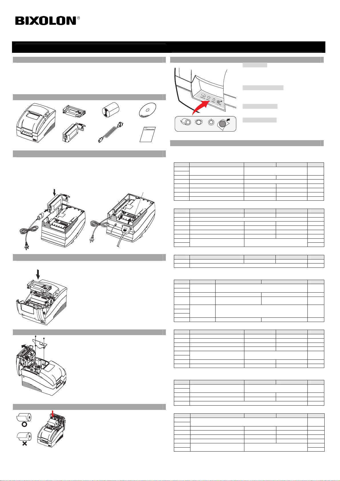
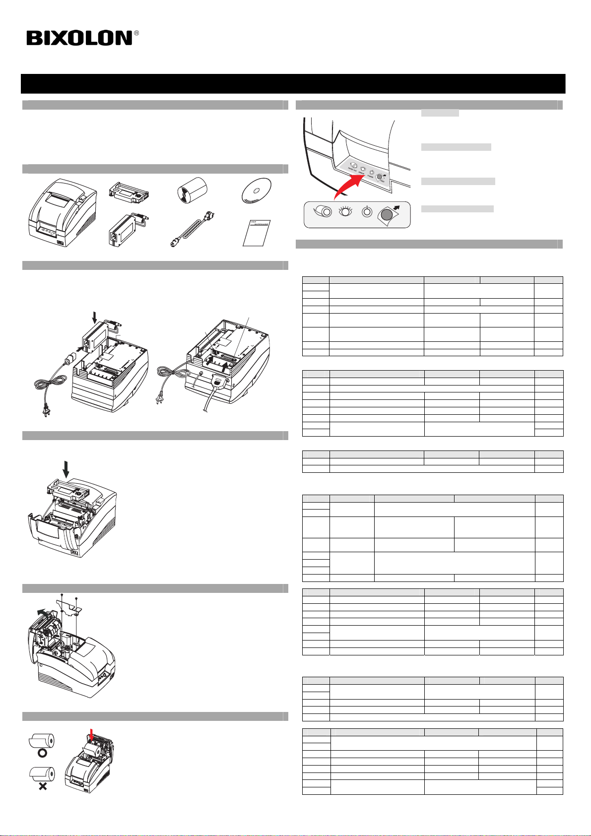
◈ Components
Ribbon Cartridge
SRP-275
AC/DC Adaptor
Power Code
◈ Connecting the cables
1. Turn off the printer and the host ECR (host computer).
2. Plug the power cord into the Adaptor, and then plug the Adaptor into the power connector
of the printer.
3. Check the interface cable (Serial, Parallel, USB, or Ethernet), and connect the interface
connector cable accordingly.
4. Plug the drawer kick-out cable into the drawer kick-out connector on the printer.
Power cord
Adaptor
Power connector
Drawer kick-out
kick-out
◈ Installing the Ribbon Cartridge
1. Before inserting the ribbon cartridge, turn the knob clockwise to prevent twisting of the ribbon.
2. Open the front cover of the printer and remove the old ribbon cartridge, if any.
◈ Changing the Paper Width
Screw (3x6) 2
pieces
Frame Paper
control
◈ Installing the Paper Roll
3. Insert the ribbon cartridge as shown in the figure so that
the ribbon is aligned to the rear of the printer head.
4. To allow the ribbon to move freely within the cartridge
when inserting the ribbon cartridge, turn the knob
clockwise once more.
5. Close the front cover of the printer.
※ Note
Malfunctions and other problems may arise if other than
specified ribbon cartridges are used in the printer. The
Warranty may be void if other than specified ribbon
cartridges are used. For detailed information regarding the
ribbon cartridge, refer to the product specifications.
1. Open the rear cover.
2. Remove the frame paper control by loosening the two
screws (3x6).
3. Place the frame paper control in the desired position and
tighten the two screws once again.
(The default paper width is set at 76mm.)
4. Close the rear cover.
5. Change the Memory Switch Setting to complete changing
the paper width. Refer to the memory switch setting
information in the user's manual.
1. Open the rear cover.
2. Insert a new paper roll, making sure to align it
properly.
3. Pull out a small amount of paper, and close the cover.
Paper Roll
connector
Drawer
Interface cable
cable
(Serial/Parallel/USB/Ethernet)
Installation Guide
Interface connecto
Procuct Installation CDProcuct Installation CD
CD
IMPACT PRINTER SRP-275 Ver.2
◈ Using the Operation Panel
• FEED (Button)
PAPER ERROR POWER FEED
◈ Setting the DIP Switches
Changing Dip Switch settings must be done when the printer is off. Any changes done while
the printer is on will not be processed.
• DIP Switch 1
SW Function ON OFF Default
1-1
Emulation Refer to the following table 1 OFF
1-2
1-3 Auto Cutter Enable Disable OFF
1-4 Reserved - OFF
1-5 Serial Interface Memory Switch DIP Switch OFF
1-6 Printing NV bit image after cutting Enable Disable OFF
1-7 Near-End Sensor Status Enable Disable OFF
1-8 Printing Lines 42/35 40/33 OFF
• DIP Switch 2 (RS232C Serial Interface Model)
SW Function ON OFF Default
2-1 Data Receive Error Ignore Print “?” OFF
2-2 Reserved OFF
2-3 Handshaking XON/XOFF DTR/DSR OFF
2-4 Data Length 7 bits 8 bits OFF
2-5 Parity Check Enable Disable OFF
2-6 Parity Selection EVEN ODD OFF
2-7 OFF
Baud Rate Selection Refer to the following table 2
2-8
• DIP Switch 2 (Parallel Interface Model)
SW Function ON OFF Default
2-1 Auto Line Feed Enable Disable OFF
2-2~8 Undefined OFF
(1) DIP Switch setting for Citizen (iDP 3550) Mode
• DIP Switch 1
SW Function ON OFF Default
1-1
Emulation Refer to the following table 1 OFF
1-2
1-3 Auto Cutter Enable Disable OFF
CBM
1-4
command
1-5
International
1-6
Character
1-7
1-8 CR Mode CR CR+LF OFF
• DIP Switch 2 (RS232C Serial Interface Mode)
SW Function ON OFF Default
2-1 Data Length 8bits 7bits ON
2-2 Parity Check Disable Enable ON
2-3 Parity Selection ODD EVEN ON
2-4 Handshaking DTR/DSR XON/XOFF ON
2-5
Baud Rate Selection Refer to the following table 2 OFF
2-6
2-7 Near-End Sensor Status Enable Disable OFF
2-8 Mechanism Type Graphic Text OFF
(2) DIP Switch setting for Star (SP500) Mode
• DIP Switch 1
SW Function ON OFF Default
1-1
Emulation Refer to the following table 1 OFF
1-2
1-3 Auto Cutter Enable Disable OFF
1-4 Printing in Black/Red Enable Disable OFF
1-5~8 Reserved OFF
• DIP Switch 2 (RS232C serial interface model)
SW Function ON OFF Default
2-1
2-2
2-3 Handshaking XON/XOFF DTR/DSR OFF
2-4 Data Length 7bits 8bits OFF
2-5 Parity Check Enable Disable OFF
2-6 Parity Selection EVEN ODD OFF
2-7 OFF
Baud Rate Selection Refer to the following table 2
2-8
Press the FEED button once to discharge extra
paper. Holding down the FEED button will
discharge paper continuously until the button is
released.
• POWER (LED, GREEN)
When turning on the power, a green LED will be
lit. Do not use the printer or turn it off when this
LED blinks)
• ERROR (LED, RED)
When an error occurs, a red LED will be lit. (e.g.
no paper, cover ajar, etc.)
• PAPER (LED, RED)
The paper LED will be red when the paper roll is
running low. If there is no paper left, the paper
LED will be on together with ‘Error’ LED.
OFF
CBM2 Mode
(iDP3530 System)
Refer to the following table 3 ON
Reserved OFF
CBM1 Mode
(iDP3540 System)
OFF
OFF
Page 2
• Table 1 – Emulation Selection • Table 2 – Transmission Speed (bps) Selection
Emulation 1-1 1-2 Transmission
BXL/POS OFF OFF 2400 ON ON ON ON
BXL/POS-KP ON ON 4800 OFF ON OFF ON
STAR OFF ON 9600 OFF OFF OFF OFF
CITIZEN ON OFF
- BXL/POS-KP (Kitchen Printer Mode): Buzzer will sound when the automatic cutting function is
activated or paper is low.
• Table 3 – International Language Selection
Country DSW1-5 DSW1-6 DSW1-7 Code Page
U.S.A ON ON ON Page 0 (PC437 : USA)
France OFF ON ON
Germany ON OFF ON
U.K OFF OFF ON
Denmark ON ON OFF
Sweden OFF ON OFF
Italy ON OFF OFF Page 2 (PC850 : Multilingual)
Windows
Code
OFF OFF OFF Windows Code
19200 ON OFF ON OFF
Setting Citizen Mode
2-7 2-8 2-5 2-6
Page 2 (PC850 : Multilingual)
Page 5 (PC865 : Nordic)
◈ Self-Test
1. Turn the printer off and close the rear cover.
2. While holding down the FEED button, turn on the printer and continue to hold until the
paper begins to feed. The self-test begins to print the printer settings and cuts the paper and
pauses. (Power indicator lamp blinks.)
3. Press the FEED button to print the rolling ASCII pattern.
4. When the rolling ASCII pattern is printed, the self-test mode automatically ends
※ Note
The self-test lets you know if your printer is operating properly. It checks the print quality,
ROM version, and DIP switch settings.
◈ Specification
Printer
Item Details
Printing Method Serial impact dot matrix
Head Pin 9-pin serial
Dot Pitch 0.352mm (1/72”)
Dot Pin Diameter 0.3mm (0.01”)
Printing Direction Bi-directional (logic seeking) with friction speed
Character per line Max 42 (Characters)
Printing speed *1) 5.1 lines/ sec
Printing Width 63.5 mm
Line Interval 4.233 mm (1/6”)
Font 7 × 9 / 9 × 9
Character Set
Alphanumeric Character : 95
International Character : 48
Extended Graphic : 128 × 27 page
SMPS Input Voltage 100~240 VAC
Frequency 50 / 60 Hz
SMPS Output Voltage 24VDC
Temperature
Humidity
Operating : 0~50℃ (32~122℉)
Storage : -10~50℃ (14~122℉)
Operating : 10~90% RH (Non-condensing)
Storage : 10~90% RH (Non-condensing)
Mechanism Life *2) 18,000,000 Lines
Auto Cutter 1,500,000 Cuts
Paper Type Paper Roll
Roll Width 76±0.5 mm, 69.5±0.5 mm, 57.5±0.5mm
Paper
Roll Diameter Max ø83 mm (3.27")
Paper Thickness Thickness : 1-ply 0.06~0.085 mm
Paper Weight Weight : 52.3~64g/m2 (0.115~0.1411 lb)
Paper Tube (Outer) Max ø19mm (0.75")
Standard RRC-201BR
Ribbon
Cartridge
※ Note
*1) Printing speed may be slower depending on the data transmission speed and the
Color Black and Red
Size 13 mm (W)
Life
RRC-201BR : 1,500,000 characters (Black)
(7×9 font continual printing, ASCII, 25℃)
750,000 characters (Red)
combination of control commands.
*2) The above values are calculated under printing level 2 with recommended paper at
normal temperature. The values may vary with environment temperature, printing level,
etc.
◈ Serial (RS-232C) Fixed Interface Model Windows Driver
Installation: SRP-275A,AG,C,CG (IFC-S TYPE)
1. After running the product installation CD, run the Impact Printer > SRP-275(A/C) >
Drivers > Windows Driver > Drivers Folder > Win SRP-275_Vx.x.x.exe file.
2. In the opening installation window, click on Next.
3. In the Ready to Install the Program window, click on Install.
4. In the Select OS Type window, click on Next.
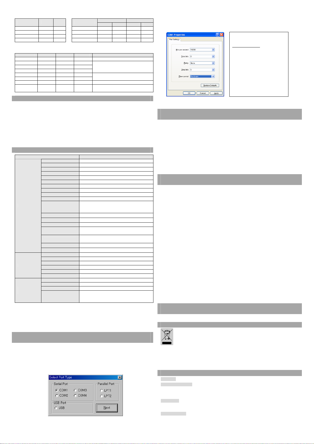
5. In the Select Port Type window, select one Serial Port and click Next.
6. In the Question window, select Yes and the computer will reboot.
(Figure 1.)
7. After rebooting, open Start > Settings > Printers & Fax > BIXOLON SRP-275 Icon >
Right-Click > Properties.
8. In the Properties window, select the Port tab and click on the Port Settings. Check to see
that the information is identical to the self-test results after installation.
<SRP-275 VER. V01.01 STB 110608>
DIP Switch setup status
Interpreter (DIP1_1,2): BXL/POS
AutoCut (DIP1 _ 3): Disabled
Memory S/W (DIP1 _ 5): Off
Logo Print (DIP1 _ 6): Off
Near_end (DIP1 _ 7): Enabled
Print Column (DIP1 _ 8): 40
Rx ErrorPrint(DIP2 _ 1): Print ?
HandShaking (DIP2 _ 3): RTS/DSR
Word Length (DIP2 _ 4): 8
Parity (DIP2 _ 5): None
Baud Rate (DIP2_7,8): 19200
9. In the Properties window, after selecting the General tab, click on Print Test Page to
confirm that printing is normal.
SELF TEST
◈ Parallel (IEEE1284) Fixed Interface Model Windows Driver
Installation: SRP-275AP,APG,CP,CPG (IFC-P TYPE)
1. After running the product installation CD, run the lmpact Printer > SRP-275(A/C) >
Drivers > Windows Driver > Drivers Folder > Win SRP-275_Vx.x.x.exe file.
2. In the opening installation window, click on Next.
3. In the Ready to Install the Program window, click on Install.
4. In the Select OS Type window, click on Next.
5. In the Select Port Type window, select one Parallel Port and click Next.
(Refer to Figure 1.)
6. In the Question window, select Yes and the computer will reboot.
7. After rebooting, open Start > Settings > Printers & Fax > BIXOLON SRP-275 Icon >
Right-Click > Properties.
8. In the Properties window, after selecting the General tab, click on Print Test Page to
confirm that printing is normal.
◈ USB Fixed Interface Model Windows Driver Installation:
SRP-275AU,AUG,CU,CUG (IFC-U TYPE)
1. After running the product installation CD, run the Impact Printer > SRP-275(A/C) >
Drivers > Windows Driver > Drivers Folder > Win SRP-275_Vx.x.x.exe file.
2. In the opening installation window, click on Next.
3. In the Ready to Install the Program window, click on Install.
4. In the Select OS Type window, click on Next.
5. In the Select Port Type window, select USB and click Next. (Refer to Figure 1.)
6-1. If using Windows 98/ME:
After completing the installation procedures, reboot the computer.①
After rebooting, turn the printer power off and back on.②
After the New Hardware Detected window appears, continue to click Next to install the ③
USB drive, and then reboot the computer once more.
6-2. If using Windows 2000:
After the ① Information window appears, turn the printer off and back on and click Yes.
After installation is complete, reboot the computer.②
6-3. If using Windows XP:
After the ① Information window appears, turn the printer off and back on and click Yes.
After the New Hardware Detected window appears, continue to click Next to install the ②
USB drive, and then reboot the computer.
Note※
When the digital registration message appears during installation, click on either OK or
Continue Anyway.
7. After rebooting, open Start > Settings > Printers & Fax > BIXOLON SRP-275 Icon >
Right-Click > Properties.
8. In the Properties window, after selecting the General tab, click on Print Test Page to
confirm that printing is normal.
◈ Ethernet Fixed Interface Model Windows Driver Installation:
SRP-275AE,AEG,CE,CEG (IFC-E TYPE)
Refer to the user manual regarding separate Ethernet interface cards.(Refer to the CD)
◈ WEEE (Waste Electrical and Electric Equipment)
This marking shown on the product or its literature, indicates that is should not be
disposed with other household wastes at the end of its working life, To prevent
possible harm to the environment or human health from uncontrolled waste disposal,
please separate this from other types of wastes and recycle it responsibly to promote
the sustainable reuse of material resources. Household users should contact either the
retailer where they purchased this product, or their local government office, for details
of where and how they can take this item for environmentally safe recycling. Business
users should contact their supplier and check the terms and conditions of the purchase
contract. This product should not be mixed with other commercial wastes for disposal.
☎ BIXOLON Co., Ltd.
● Website http://www.bixolon.com
● Korea Headquarters
(Add) Digital Empire Block A, 5th Floor, 980-3 Yeongtong-dong, Yeongtong-gu, Suweon-shi,
Gyeonggi-do, Korea 443-813
(Tel.) +82-31-218-5500
● U.S. Office
(Add) BIXOLON America Inc., 1210 E. 223rd St., #330, Carson, CA 90745
(Tel.) +1-858 764 4580
● Germany Office
(Add) BIXOLON Germany GmbH, Tiefenbroicher Weg 35 40472 Düsseldorf
(Tel.) +49 (0)211 68 78 54 0
Page 3
Procuct Installation CD
Guide d’installation de l’imprimante
◈ Information
Ce guide d’installation comprend de brèves informations nécessaires à l'installation du produit. Pour des
informations plus détaillées concernant l’installation, veuillez vous reporter au manuel d’utilisation
disponible sur le CD fourni. Le contenu du CD est le suivant :
1. Manuel : Manuel d’utilisation, schéma des codes, commandes de contrôle
2. Pilotes : Pilotes Windows, pilotes Système d’exploitation
3. Utilitaires : Un outil de téléchargement de logo et un outil de bascule de commande de la mémoire
virtuelle
◈ Composants
Cartouche de ruban Rouleau de papier
SRP-275
◈ Connexion des câbles
1. Eteindre l'imprimante ainsi que la caisse enregistreuse électronique hôte (ordinateur hôte).
2. Brancher le cordon d'alimentation dans l'adaptateur, puis, brancher l'adaptateur dans la prise
d'alimentation de l'imprimante.
3. Vérifier le câble d’interface (Série, Parallèle, USB ou Ethernet) puis le connecter en conséquence.
4. Brancher le câble d’ouverture du tiroir dans le connecteur d'ouverture du tiroir de l'imprimante.
Cordon
d’alimentation
◈ Installation de la cartouche du ruban
1. Avant d’insérer la cartouche de ruban, tourner le bouton dans le sens des aiguilles d'une montre afin
d'éviter que le ruban ne s'enroule.
2. Ouvrir le panneau avant de l’imprimante et retirer l’ancienne cartouche de ruban, le cas échéant.
Adaptateur CA/CC Cordon d’alimentation Guide d’installation
Adaptateur
◈ Changement de la largeur du papier
2 vis (3x6)
Commande de la
trame de papier
◈ Installation du rouleau de papier
Connecteur d’ouverture
Connecteur
d’alimentation
3. Insérer la cartouche de ruban tel que le montre schéma de
manière à ce que le ruban soit aligné vers l'arrière de la tête
d'impression.
4. Afin de permettre au ruban de se déplacer librement à
l’intérieur de la cartouche, lors de l’insertion de cartouche de
ruban, tourner de nouveau le bouton dans le sens des aiguilles
d’une montre.
5. Fermer le panneau avant de l’imprimante.
Note※
Des dysfonctionnements et divers problèmes peuvent survenir si
d’autres cartouches de ruban que celles spécifiées sont utilisées.
En cas d’utilisation d’autres cartouches de ruban spécifiées, la
garantie peut être annulée.
Pour de plus amples informations relatives à la cartouche de
ruban, veuillez vous reporter aux caractéristiques techniques du
produit.
1. Ouvrir le panneau arrière.
2. Retirer la commande de papier de la trame en desserrant les
deux vis (3x6).
3. Placer la commande du papier de la trame dans la direction
souhaitée puis resserrer les deux vis.
(la largeur du papier par défaut est de 76 mm.)
4. Fermer le panneau arrière.
5. Modifier le paramétrage du commutateur de mémoire afin de
terminer le changement de la largeur de papier. Se reporter au
manuel d’utilisation pour obtenir des informations relatives au
paramétrage du commutateur de mémoire.
1. Ouvrir le panneau arrière.
2. Insérer un nouveau rouleau de papier et s’assurer qu’il est
correctement aligné.
3. Sortir une petite quantité de papier puis refermer le couvercle.
Câble
d’ouverture
du tiroir
du tiroir
Connecteur d’interface
Câble d’interface
(Série/Parallèle/USB/Ethernet)
Procuct Installation CDProcuct Installation CD
CD
IMPRIMANTE À IMPACT SRP-275
◈ Utilisation du panneau de fonctions
ERROR
PAPER
◈ Paramétrage des commutateurs DIP
La modification des paramètres des commutateurs DIP doit être effectuée lorsque l’imprimante est éteinte.
Toute modification effectuée lorsque l’imprimante est allumée ne sera pas traitée.
• Commutateur DIP 1
COM Fonction ON OFF Défaut
1-1
1-2
1-3 Machine de coupe automatique Activée Désactivée OFF
1-4 Réservé - OFF
1-5 Interface série
1-6
1-7 Statut du capteur de presque fin Activé Désactivé OFF
1-8 Impression des lignes 42/35 40/33 OFF
• Commutateur DIP 2 (Modèle Interface série RS232C)
COM Fonction ON OFF Défaut
2-1 Erreur de réception de données Ignoré Impression “?” OFF
2-2 Réservé OFF
2-3 Etablissement d’une liaison XON/XOFF DTR/DSR OFF
2-4 Longueur des données 7 bits 8 bits OFF
2-5 Contrôle de parité Activé Désactivé OFF
2-6 Sélection de la parité PAIRE IMPAIRE OFF
2-7 OFF
2-8
• Commutateur DIP 2 (Modèle Interface Parallèle)
COM Fonction ON OFF Défaut
2-1 Saut de ligne automatique Activé Désactivé OFF
2-2~8 Indéfini OFF
(1) Paramétrage du commutateur DIP pour le modèle Citizen (iDP3550)
• Commutateur DIP 1
COM Fonction ON OFF Défaut
1-1
1-2
1-3
1-4
1-5
1-6
1-7
1-8 Mode CR CR CR+LF OFF
• Commutateur DIP 2 (Modèle Interface série RS232C)
COM Fonction ON OFF Défaut
2-1 Longueur des données 8 bits 7 bits ON
2-2 Contrôle de parité Désactivé Activé ON
2-3 Sélection de la parité IMPAIRE PAIRE ON
2-4 Etablissement d’une liaison DTR/DSR XON/XOFF ON
2-5
2-6
2-7 Statut du capteur de presque fin Activé Désactivé OFF
2-8 Type de mécanisme Graphique Texte OFF
(2) Paramétrage du commutateur DIP pour le modèle Star (SP500)
• Commutateur DIP 1
COM Fonction ON OFF Défaut
1-1
1-2
1-3 Machine de coupe automatique Activée Désactivée OFF
1-4 Impression en Noir / Rouge Activée Désactivée OFF
1-5~8 Réservé OFF
• Commutateur DIP 2 (Modèle Interface série RS232C)
COM Fonction ON OFF Défaut
2-1
2-2
2-3 Etablissement d’une liaison XON/XOFF DTR/DSR OFF
2-4 Longueur des données 7 bits 8 bits OFF
2-5 Contrôle de parité Activé Désactivé OFF
2-6 Sélection de la parité PAIRE IMPAIRE OFF
2-7 OFF
2-8
POWER FEED
Emulation Se reporter au tableau 1 suivant OFF
Impression d’une image bit NV
après la coupe
Sélection du débit en bauds Se reporter au tableau 2 suivant
Emulation Se reporter au tableau 1 suivant OFF
Machine de
coupe
automatique
Commande
CBM
Caractère
international
Sélection du débit en bauds Se reporter au tableau 2 suivant OFF
Emulation Se reporter au tableau 1 suivant OFF
Sélection du débit en bauds Se reporter au tableau 2 suivant
• FEED (Bouton)
Appuyer une fois sur le bouton FEED pour retirer le
surplus de papier. Appuyer sur le bouton FEED jusqu’à ce
que tout le surplus du papier soit dégagé.
• POWER (VOYANT, VERT)
Lorsque l'imprimante est allumée, un voyant vert s'allume.
Ne pas utiliser l’imprimante, ni l’éteindre lorsque le voyant
clignote)
• ERROR (VOYANT, ROUGE)
Lorsqu’une erreur survient, un voyant rouge s’allume. (ex.
Plus de papier couvercle entrouvert, etc.)
• PAPER (VOYANT, ROUGE)
Lorsque le rouleau de papier est presque terminé, le voyant
papier deviendra rouge. S’il n’y a plus de papier, le voyant
papier ainsi que le voyant « Erreur » seront allumés.
Commutateur
Mémoire
Activée Désactivée OFF
Activée Désactivée OFF
Modèle CBM2
(Système iDP3530)
Se reporter au tableau 3 suivant ON
Réservé OFF
Commutateur DIP OFF
Modèle CBM1
(Système iDP3540)
OFF
OFF
OFF
Page 4

• Tableau 1 – Sélection d’émulation • Tableau 2 – Sélection de la vitesse de transmission (bps)
Emulation 1-1 1-2 Transmission
BXL/POS OFF OFF 2400 ON ON ON ON
BXL/POS-KP ON ON 4800 OFF ON OFF ON
STAR OFF ON 9600 OFF OFF OFF OFF
CITIZEN ON OFF
- BXL/POS-KP (Modèle d’imprimante Cuisine) : Un bip retentira lorsque la fonction de coupe
automatique sera activée et lorsqu'il ne resta plus beaucoup de papier.
• Tableau 3 – Sélection de la langue internationale
Pays DSW1-5 DSW1-6 DSW1-7 Page de codes
U.S.A ON ON ON Page 0 (PC437 : USA)
France OFF ON ON
Allemagne ON OFF ON
R.-U. OFF OFF ON
Danemark ON ON OFF
Suède OFF ON OFF
Italie ON OFF OFF Page 2 (PC850 : Multilingue)
Code Windows OFF OFF OFF Code Windows
◈ Autotest
1. Eteindre l’imprimante et fermer le panneau arrière.
2. Tout en maintenant le bouton ALIMENTATION, allumer l’imprimante et continuer à appuyer sur
le bouton jusqu’à ce que le papier commence à se charger. L’autotest commence par imprimer le
paramétrage de l’imprimante, coupe le papier puis se met en pause. (Le voyant de la mise sous
tension clignote)
3. Appuyer sur le bouton ALIMENTATION pour imprimer le modèle ASCII du défilement vertical.
4. Une fois le modèle ASCII de défilement vertical imprimé, l’autotest s’arrêtera automatiquement.
Note※
L’autotest vous indique si votre imprimante fonctionne correctement. Il vérifie la qualité
d’impression, la version ROM ainsi que les paramétrages des commutateurs DIP.
◈ Caractéristique technique
Imprimante
Papier
Cartouche de
ruban
Note※
*1) La vitesse d’impression peut être ralentie en fonction de la vitesse de transmission des données ainsi que
la combinaison des commandes de contrôle.
*2) Les valeurs ci-dessus sont calculés sur une imprimante de niveau 2 avec le papier recommandé et sous
une température normale.
Les valeurs peuvent varier selon la température ambiante, le niveau d’impression, etc.
Elément Détails
Méthode d’impression Matrice à points à impacte en série
Broche de la tête Série à 9 broches
Taille de pixel 0,352 mm
Diamètre de la broche
du point
Sens d’impression
Caractères par ligne 42 max. (caractères)
Vitesse d’impression *1) 5,1 Ligne par seconde
Largeur d’impression 63,5 mm
Intervalle entre les
lignes
Police 7 × 9 / 9 × 9
Jeu de caractères
SMPS Tension d’entrée 100~240 VCC
Fréquence 50 / 60 Hz
SMPS Tension de sortie 24VCC
Température
Humidité
Durée de vie du
mécanisme *2)
Machine de coupe
automatique
Type de papier Rouleau de papier
Largeur du rouleau 76 ± 0,5 mm, 69,5 ± 0,5 mm, 57,5 ± 0,5mm
Diamètre du rouleau ø83 mm max
Epaisseur du papier Epaisseur : Monocouche 0,06 ~0,085 mm
Poids du papier Poids : 52,3~64g/m2
Tube du papier
(extérieur)
Standard RRC-201BR
Couleur Noir et Rouge
Taille 13 mm (L)
Durée de vie
19200 ON OFF ON OFF
0,3 mm
Bidirectionnel (recherche logique) avec vitesse de
friction
4,233 mm
Caractère alphanumérique : 95
Caractère international : 48
Graphique étendu : Page 128 x 27
Lors de l’utilisation : 0~50 (32~122 )℃℉
Stockage : -10~50 (14~122 )℃℉
Lors de l’utilisation : 10~90% HR (Non condensée)
Stockage : 10~90% HR (Non condensée)
18 000 000 lignes
1 500 000 coupes
ø19mm max.
RRC-201BR : 1 500 000 caractères (Noir)
Impression continue en police 7 x 9, ASCII, 25 )℃
paramètres des Modèle Citizen
2-7 2-8 2-5 2-6
Page 2 (PC850 : Multilingue)
Page 5 (PC865 : Nordique)
750 000 caractères (Rouge)
◈ Installation du pilote Windows du modèle d’interface fixe série
(RS-232 C) : SRP-275A,AG,C,CG (IFC-S TYPE)
1. Après avoir lancé le CD d’installation du produit, lancer le fichier imprimante > SRP-275 (C/A) >
Pilotes > Pilote Windows > Fichier Pilotes > Win SRP-275_Vx.x.x.exe
2. Dans la fenêtre de demande d’installation, cliquer sur Suivant.
3. Dans la fenêtre Prêt à installer le programme, cliquer sur Installer.
4. Dans la fenêtre Sélectionner un type de système d’exploitation, cliquer sur Suivant
5. Dans la fenêtre Sélectionner un type de port, sélectionner un Port Série puis cliquer sur Suivant.
[schéma 1]
8. Dans la fenêtre Propriétés, sélectionner l’onglet Port puis cliquer sur Paramètres Port. Vérifier que les
informations sont identiques aux résultats de l’autotest après installation.
<SRP-275 VER. V01.01 STB 110608>
DIP Switch setup status
Interpreter (DIP1_1,2): BXL/POS
AutoCut (DIP1 _ 3): Disabled
Memory S/W (DIP1 _ 5): Off
Logo Print (DIP1 _ 6): Off
Near_end (DIP1 _ 7): Enabled
Print Column (DIP1 _ 8): 40
Rx ErrorPrint (DIP2 _ 1): Print ?
HandShaking (DIP2 _ 3): RTS/DSR
Word Length (DIP2 _ 4): 8
Parity (DIP2 _ 5): None
Baud Rate (DIP2_7,8): 19200
9. Dans la fenêtre Propriétés, après avoir sélectionné l’onglet Général, cliquer sur Page de test d’impression
afin de confirmer que l’impression est normale.
SELF TEST
◈ Installation du pilote Windows du modèle d’interface fixe parallèle
(IEEE1284) : SRP-275AP,APG,CP,CPG (IFC-P TYPE)
1. Après avoir lancé le CD d’installation du produit, lancer le fichier imprimante à impact > SRP-275
(C/A) > Pilotes > Pilote Windows > Fichier Pilotes > Win SRP-275_Vx.x.x.exe
2. Dans la fenêtre de demande d’installation, cliquer sur Suivant.
3. Dans la fenêtre Prêt à installer le programme, cliquer sur Installer.
4. Dans la fenêtre Sélectionner un type de système d’exploitation, cliquer sur Suivant
5. Dans la fenêtre Sélectionner un type de port, sélectionner un Port Parallèle puis cliquer sur Suivant.
(Se reporter au schéma 1)
6. Dans la fenêtre Question, sélectionner Oui puis l’ordinateur redémarrera.
7. Après le redémarrage, ouvrir Démarrer > Paramètres > Imprimantes et Fax > Icône BIXOLON SRP-275
> Clic droit > Propriétés.
8. Dans la fenêtre Propriétés, après avoir sélectionné l’onglet Général, cliquer sur Page de test d’impression
afin de confirmer que l’impression est normale.
◈ Installation du pilote Windows du modèle d’interface fixe USB
: SRP-275AU,AUG,CU,CUG (IFC-U TYPE)
1. Après avoir lancé le CD d’installation du produit, lancer le fichier imprimante > SRP-275 (C/A) >
Pilotes > Pilote Windows > Fichier Pilotes > Win SRP-275_Vx.x.x.exe
2. Dans la fenêtre de demande d’installation, cliquer sur Suivant.
3. Dans la fenêtre Prêt à installer le programme, cliquer sur Installer.
4. Dans la fenêtre Sélectionner un type de système d’exploitation, cliquer sur Suivant
5. Dans la fenêtre Sélectionner un type de port, sélectionner USB puis cliquer sur Suivant.
[Se reporter au schéma 1]
6-1. Sous Windows 98/ME :
Une fois les procédures d’installation terminées, redémarrer l’ordinateur.①
Après le redémarrage, éteindre l'imprimante puis la rallumer.②
Quand la fenêtre Nouveau matériel détecté apparaît, continuer en cliquant sur Suivant pour installer le ③
pilote USB, puis redémarrer de nouveau l'ordinateur.
6-2. Sous Windows 2000 :
Quand la fenêtre ① Information apparaît, éteindre l'imprimante et la rallumer, puis cliquer sur Oui.
Une fois l’installation terminée, redémarrer l’ordinateur.②
6-3. Sous Windows XP :
① Quand la fenêtre Information apparaît, éteindre l'imprimante et la rallumer, puis cliquer sur Oui.
Quand la fenêtre Nouveau matériel détecté apparaît, continuer en cliquant sur Suivant pour installer le ②
pilote USB, puis redémarrer de nouveau l'ordinateur.
Note※
Lorsque le message d’enregistrement en ligne apparaît lors de l’installation, cliquer sur OK ou sur
Continuer quand même.
7. Après le redémarrage, ouvrir Démarrer > Paramètres > Imprimantes et Fax > Icône BIXOLON SRP-275
> Clic droit > Propriétés.
8. Dans la fenêtre Propriétés, après avoir sélectionné l’onglet Général, cliquer sur Page de test d’impression
afin de confirmer que l’impression est normale.
◈ Installation du pilote Windows du modèle d’interface fixe Ethernet
: SRP-275AE,AEG,CE,CEG (IFC-E TYPE)
Se reporter au manuel d’utilisation de chaque carte d’interface Ethernet (Se reporter au CD)
◈ WEEE (Waste Electrical and Electric Equipment)
L’indication que comportent le produit ou son étiquette, signifie qu’il ne doit pas être traité
avec les autres déchets domestiques, lorsqu’il ne sera plus utilisable. Son utilisateur devra le
séparer d’autres types de déchets pour son recyclage, afin d’empêcher que son mauvais
traitement ne nuise à l’environnement ou à la santé publique, ce qui contribuera à la
réutilisation durable de ressources. Pour un produit à usage domestique, il faut contacter le
point de vente où vous avez acheté votre produit, ou les autorités locales, pour vous
renseigner sur les décharges où le produit usé doit être mis, dans le cadre de sa réutilisation
assurant la sécurité environnementale. Pour un produit à usage industriel, il faut appeler son
fournisseur pour vérifier les conditions de vente. Une fois usé, ce produit ne doit pas être
traité avec les autres déchets industriels et commerciaux.
☎ BIXOLON Co., Ltd.
● Site Internet http://www.bixolon.com
● Siège en Corée
(Adr.) Digital Empire Bloc A, 5e étage, 980-3 Yeongtong-dong, Yeongtong-gu, Suweon-shi,
Gyeonggi-do, Corée 443-813
(Tél.) +82-31-218-5500
● Bureau aux Etats-Unis
(Adr.) BIXOLON America Inc., 1210 E. 223rd St., #330, Carson, CA 90745
(Tél.) +1-858 764 4580
● Bureau en Allemagne
(Adr.) BIXOLON Germany GmbH, Tiefenbroicher Weg 35 40472 Düsseldorf
(Tél.) +49 (0)211 68 78 54 0
6. Dans la fenêtre Question, sélectionner Oui puis l’ordinateur redémarrera.
7. Après le redémarrage, ouvrir Démarrer > Paramètres > Imprimantes et Fax > Icône BIXOLON SRP-275
> Clic droit > Propriétés.
Page 5

Procuct Installation CD
a
a
Guía de instalación de la impresora
◈ Información
Esta Guía de instalación incluye un breve resumen de la información necesaria para la
instalación del producto. Para obtener información de instalación más detallada, consulte el
manual del usuario que se encuentra en el CD adjunto. Los contenidos del CD incluyen lo
siguiente.
1. Manual: Manual del usuario, Tabla de códigos, Comandos de control
2. Controladores: Controladores para Windows, controladores OPOS
3. Programas utilitarios: herramienta para descarga de logos y herramienta de memoria
virtual para el control de interruptores
◈ Componentes
Cartucho de cinta
SRP-275
Adaptador AC/DC Cable de energía
Rollo de papel
Cómo conectar los cables◈
1. Apague la impresora y la caja registradora principal (computadora principal).
2. Conecte el cable de energía al adaptador, y luego, el adaptador al conector de alimentación
de la impresora.
3. Verifique el cable de interfaz (Serie, Paralelo, USB, o Ethernet), y conecte el cable
conector de interfaz adecuadamente.
4. Conecte el cable de la gaveta de expulsión en el conector de la gaveta de expulsión de la
impresora.
Cable de
energí
Cómo instalar el cartucho de cinta◈
1. Antes de insertar el cartucho de cinta, gire la perilla en el sentido de las agujas del reloj para evitar
que la cinta se enrosque.
2. Abra la tapa frontal de la impresora y quite el cartucho de cinta usado, si lo hay.
Adaptador
Conector de
alimentación
3. Inserte el cartucho de cinta como muestra la figura para
4. Para que la cinta se mueva con libertad dentro del
5. Cierre la tapa frontal de la impresora.
Pueden surgir fallas y otros problemas si se usan otros
cartuchos aparte de los especificados. La Garantía puede
quedar inválida si se usan cartuchos de cinta no
especificados. Para obtener información detallada sobre el
cartucho de cinta, consulte las especificaciones del producto.
Conector de la gavet
Cable de la
que la cinta esté alineada con la parte trasera del cabezal
de la impresora.
cartucho, cuando inserte el cartucho, gire la perilla una
vez más en el sentido de las agujas del reloj.
Nota※
◈ Cómo cambiar el ancho del papel
Tornillos (3x6)
2 piezas
Marco de control
del papel
◈ Cómo instalar el rollo de papel
1. Abra la tapa trasera.
2. Quite el marco de control del papel aflojando los dos
tornillos (3x6).
3. Coloque el marco de control del papel en la posición
que desee y vuelva a ajustar los tornillos.
(El ancho predeterminado del papel está configurado
en 76 mm.)
4. Cierre la tapa trasera.
5. Cambie la Configuración del interruptor de memoria
para completar el cambio del ancho del papel.
Consulte la información de configuración del
interruptor de memoria que se encuentra en el manual
del usuario.
1. Abra la tapa trasera.
2. Inserte un nuevo rollo de papel, asegurándose de
alinearlo adecuadamente.
3. Quite una pequeña cantidad de papel y cierre la tapa.
de expulsión
gaveta de
expulsión
Guía de instalación
Conector interfaz
Cable interfaz
(Serie/Paralelo/USB/Ethernet)
Procuct Installation CDProcuct Installation CD
CD
IMPRESORA DE IMPACTO SRP-275
◈ Cómo usar el panel de funcionamiento
PAPER ERROR POWER FEED
◈ Cómo configurar los interruptores DIP
Para cambiar la configuración de los interruptores DIP, la impresora debe estar apagada. Los cambios que
se realicen mientras la impresora esté encendida no se procesarán.
• Interruptor DIP 1
INT Función ENCENDIDO APAGADO Predeterminado
1-1
Emulación Consulte la siguiente tabla 1 APAGADO
1-2
1-3 Cortador automático Activar Desactivar APAGADO
1-4 Reservado
1-5 Interfaz serie
Impresión de la imagen por bit NV
1-6
después de cortar
Estado del sensor de Casi
1-7
TERMINADO
1-8 Líneas de impresión 42/35 40/33 APAGADO
• Interruptor DIP 2 (RS232C Modelo de interfaz serie)
INT Función ENCENDIDO APAGADO Predeterminado
2-1 Error de recepción de datos Ignorar Imprimir “?” APAGADO
2-2 Reservado APAGADO
2-3 Entrada en comunicación XON/XOFF DTR/DSR APAGADO
2-4 Longitud de datos 7 bits 8 bits APAGADO
2-5 Control de paridad Activar Desactivar APAGADO
2-6 Selección de paridad PAR IMPAR APAGADO
2-7 APAGADO
Selección de velocidad de
transmisión
2-8
• Interruptor DIP 2 (Modelo de interfaz paralela)
INT Función ENCENDIDO APAGADO Predeterminado
2-1 Alimentación de línea automática Activar Desactivar APAGADO
2-2~8 Indefinido APAGADO
(2) Configuración de interruptores DIP para el modo Citizen (iDP 3550)
• Interruptor DIP 1
INT Función ENCENDIDO APAGADO Predeterminado
1-1
Emulación Consulte la siguiente tabla 1 APAGADO
1-2
1-3 Cortador automático Activar Desactivar APAGADO
1-4 Comando CBM
1-5
Caracter internacional Consulte la siguiente tabla 3 ENCENDIDO
1-6
1-7
1-8 Modo CR CR CR+LF APAGADO
• Interruptor DIP 2 (RS232C Modo de interfaz serie)
INT Función ENCENDIDO APAGADO Predeterminado
2-1 Longitud de datos 8bits 7bits ENCENDIDO
2-2 Control de paridad Desactivar Activar ENCENDIDO
2-3 Selección de paridad IMPAR PAR ENCENDIDO
2-4 Entrada en comunicación DTR/DSR XON/XOFF ENCENDIDO
2-5
Selección de velocidad de
transmisión
2-6
Estado del sensor de Casi
2-7
TERMINADO
2-8 Tipo de mecanismo Gráfico Texto APAGADO
3. Configuración de interruptores DIP para el modo Star (SP500)
• Interruptor DIP 1
INT Función ENCENDIDO APAGADO Predeterminado
1-1
Emulación Consulte la siguiente tabla 1 APAGADO
1-2
1-3 Cortador automático Activar Desactivar APAGADO
1-4 Impresión en negro/rojo Activar Desactivar APAGADO
1-5~8 Reservado APAGADO
• Interruptor DIP 2 (RS232C modelo de interfaz serie)
INT Función ENCENDIDO APAGADO Predeterminado
2-1
2-2
2-3 Entrada en comunicación XON/XOFF DTR/DSR APAGADO
2-4 Longitud de datos 7bits 8bits APAGADO
2-5 Control de paridad Activar Desactivar APAGADO
2-6 Selección de paridad PAR IMPAR APAGADO
2-7 APAGADO
Selección de velocidad de
transmisión
2-8
• FEED (Botón)
Presione una vez el botón de ALIMENTACIÓN para
expulsar más papel. Si mantiene presionado el botón de
ALIMENTACIÓN, descargará papel continuamente hasta
que lo suelte.
• POWER (LED, VERDE)
Cuando conecte la energía, se encenderá un LED verde.
No apague la impresora cuando este LED parpadee.
• ERROR (LED, ROJO)
Cuando ocurra un error, se encenderá un LED rojo. (por
ej.: no hay papel, la tapa está entreabierta, etc.)
• PAPER (LED, ROJO)
El LED de papel estará rojo cuando el rollo de papel esté
por terminarse. Si ya no queda papel, el LED de papel
estará encendido junto con el LED de “Error”.
Interruptor de
memoria
Activar Desactivar APAGADO
Activar Desactivar APAGADO
Consulte la siguiente tabla 2
Modo CBM2
(Sistema iDP3530)
Consulte la siguiente tabla 2 APAGADO
Activar Desactivar APAGADO
Reservado
Consulte la siguiente tabla 2
-
Interruptor DIP APAGADO
Modo CBM1
(Sistema iDP3540)
APAGADO
APAGADO
APAGADO
APAGADO
APAGADO
Page 6

• Tabla 1 – Selección de emulación • Tabla 2 – Selección de velocidad de transmisión (bps)
Emulación 1-1 1-2 Transmisión
BXL/POS APAGADO APAGADO 2400 ENCENDIDO ENCENDIDO ENCENDIDOENCENDIDO
BXL/POS-
ENCENDIDO ENCENDIDO 4800 APAGADO ENCENDIDO APAGADO ENCENDIDO
KP
STAR APAGADO ENCENDIDO 9600 APAGADO APAGADO APAGADO APAGADO
CITIZEN ENCENDIDO APAGADO 19200 ENCENDIDO APAGADO ENCENDIDO APAGADO
- BXL/POS-KP (Impresora modelo de cocina): El timbre sonará cuando la función de corte automático
esté activada o cuando haya poco papel.
• Tabla 3 – Selección de lenguaje internacional
País IN.DIP1-5 IN.DIP1-6 IN.DIP1-7 Página del código
EE.UU. ENCENDIDO ENCENDIDO ENCENDIDO Página 0 (PC437 : EE.UU.)
Francia APAGADO ENCENDIDO ENCENDIDO
Alemania ENCENDIDO APAGADO ENCENDIDO
R.U. APAGADO APAGADO ENCENDIDO
Dinamarca ENCENDIDO ENCENDIDO APAGADO
Suecia APAGADO ENCENDIDO APAGADO
Italia ENCENDIDO APAGADO APAGADO Página 2 (PC850 : Multilingüe)
Código de Windows APAGADO APAGADO APAGADO Código de Windows
◈ Autoevaluación
1. Apague la impresora y cierre la tapa trasera.
2. Mientras mantiene presionado el botón de ALIMENTACIÓN, encienda la impresora y continúe
presionando hasta que comience a tomar el papel. La autoevaluación comienza a imprimir la
configuración de la impresora, corta el papel y hace una pausa. (La luz indicadora de encendido
parpadea.)
3. Presione el botón de ALIMENTACIÓN para imprimir el patrón ASCII.
4. Cuando este patrón se haya impreso, el modo de autoevaluación terminará automáticamente.
Nota※
La autoevaluación le permite saber si su impresora funciona correctamente. Comprueba la calidad
de impresión, la versión ROM y la configuración de los interruptores DIP.
◈ Especificación
Impresora
Papel
Cartucho de
cinta
Nota※
*1) La velocidad de impresión puede ser más lenta según la velocidad de transmisión de datos y la
combinación de los comandos de control.
*2) Los valores anteriores se calculan en el nivel 2 de impresión con el papel recomendado a la
temperatura normal.
Los valores pueden variar de acuerdo a la temperatura ambiente, al nivel de impresión, etc.
Elemento Detalles
Método de impresión Matriz de puntos de impacto en serie
Aguja Serie de 9 agujas
Tamaño de puntos 0,352 mm (1/72”)
Diámetro del punto de la
aguja
Dirección de impresión
Caracteres por línea Máx. 42 (caracteres)
Velocidad de impresión
*1)
Ancho de impresión 63,5 mm
Intervalo de líneas 4,233 mm (1/6”)
Fuente 7 × 9 / 9 × 9
Conjunto de caracteres
SMPS Tensión de
entrada
Frecuencia 50 / 60 Hz
SMPS Tensión de salida 24VDC
Temperatura
Humedad
Vida útil del mecanismo
*2)
Cortador automático 1.500.000 cortes
Tipo de papel Rollo de papel
Ancho del rollo 76±0,5 mm, 69,5±0,5 mm, 57,5±0,5mm
Diámetro del rollo Máx. ø83 mm (3,27")
Espesor del papel Espesor : 1 capa 0,06~0,085 mm
Peso del papel Peso : 52,3~64g/m2 (0,115~0,1411 lb)
Tubo de papel (exterior) Máx. ø19 mm (0,75")
Estándar RRC-201BR
Color Rojo y negro
Tamaño 13 mm (ancho)
Vida útil
0,3 mm (0,01”)
Bidirectional (búsqueda lógica) con velocidad de
fricción
5,1 línea por segundo
Caracteres alfanuméricos : 95
Caracteres internacionales : 48
Gráfico extendido : página de 128 × 27
100~240 VAC
Funcionamiento : 0~50 (32~122 )℃℉
Almacenamiento : -10~50 (14~122 )℃℉
Funcionamiento : 10~90% HR (no condensante)
Almacenamiento : 10~90% HR (no condensante)
18.000.000 líneas
RRC-201BR : 1.500.000 caracteres (Negro)
(7×9 impresión continua de la fuente, ASCII, 25 )℃
Modo Modo Citizen
2-7 2-8 2-5 2-6
Página 2 (PC850 : Multilingüe)
Página 5 (PC865 : Nórdico)
750.000 caracteres (Negro)
◈ Instalación de los controladores de Windows del modelo de interfaz
serie fijo (RS-232C): SRP-275A, AG, C, CG (IFC-S TYPE)
1. Después de ejecutar el CD de instalación del producto, ejecute el archivo Impresora de impacto
> SRP-275 (A/C) > Controladores > Controladores de Windows > Carpeta de controladores
> Win SRP-275_Vx.x.x.exe.
2. En la ventana que se abra para la instalación, haga clic en Siguiente.
3. En la ventana Preparado para instalar el programa, haga clic en Instalar.
4. En la ventana Seleccione el tipo de Sistema Operativo, haga clic en Siguiente.
5. En la ventana Seleccione tipo de puerto, seleccione un Puerto serie y haga clic en Siguiente.
6. En la ventana Pregunta, seleccione Sí y la computadora se reiniciará.
(figura 1.)
7. Después de reiniciar, vaya a Inicio > Configuración >Impresoras y Faxes > Icono BIXOLON
SRP-275 > Clic derecho >Propiedades.
8. En la ventana Propiedades, seleccione la pestaña Puerto y haga clic en Configuración de puerto.
Compruebe que la información sea idéntica a los resultados de la autoevaluación realizada
después de la instalación.
<SRP-275 VER. V01.01 STB 110608>
DIP Switch setup status
Interpreter (DIP1_1,2): BXL/POS
AutoCut (DIP1 _ 3): Disabled
Memory S/W (DIP1 _ 5): Off
Logo Print (DIP1 _ 6): Off
Near_end (DIP1 _ 7): Enabled
Print Column (DIP1 _ 8): 40
Rx ErrorPrint (DIP2 _ 1): Print ?
HandShaking (DIP2 _ 3): RTS/DSR
Word Length (DIP2 _ 4): 8
Parity (DIP2 _ 5): None
Baud Rate (DIP2_7,8): 19200
9. En la ventana Propiedades, después de seleccionar la pestaña General, haga clic en Imprimir
página de prueba para confirmar que la impresión sea normal.
SELF TEST
◈ Instalación de los controladores de Windows del modelo de interfaz
paralela fija (IEEE1284): SRP-275AP, APG, CP, CPG (IFC-P TYPE)
1. Después de ejecutar el CD de instalación del producto, ejecute el archivo Impresora de impacto
> SRP-275 (A/C) > Controladores > Controladores de Windows > Carpeta de
Controladores > Win SRP-275_Vx.x.x.exe.
2. En la ventana que se abra para la instalación, haga clic en Siguiente.
3. En la ventana Preparado para instalar el programa, haga clic en Instalar.
4. En la ventana Seleccione el tipo de Sistema Operativo, haga clic en Siguiente.
5. En la ventana Seleccione tipo de puerto, seleccione un Puerto paralelo y haga clic en Siguiente.
(Remítase a la figura 1.)
6. En la ventana Pregunta, seleccione Sí y la computadora se reiniciará.
7. Después de reiniciar, vaya a Inicio > Configuración >Impresoras y Faxes > Icono BIXOLON
SRP-275 > Clic derecho >Propiedades.
8. En la ventana Propiedades, después de seleccionar la pestaña General, haga clic en Imprimir
página de prueba para confirmar que la impresión sea normal.
◈ Instalación de los controladores de Windows del modelo de interfaz USB
fija: SRP-275AU, AUG, CU, CUG (IFC-U TYPE)
1. Después de ejecutar el CD de instalación del producto, ejecute el archivo Impresora de impacto
> SRP-275 (A/C) > Controladores > Controladores de Windows > Carpeta de controladores
> Win SRP-275_Vx.x.x.exe.
2. En la ventana que se abra para la instalación, haga clic en Siguiente.
3. En la ventana Preparado para instalar el programa, haga clic en Instalar.
4. En la ventana Seleccione el tipo de Sistema Operativo, haga clic en Siguiente.
5. En la ventana Seleccione tipo de puerto, seleccione un USB y haga clic en Siguiente.
(Remítase a la figura 1.)
6-1. Si usa Windows 98/ME:
① Después de completar los procedimientos de instalación, reinicie la computadora.
② Una vez que se reinició, apague la impresora y vuelva a encenderla.
③ Cuando aparezca la ventana Nuevo hardware encontrado, siga haciendo clic en Siguiente para
instalar el controlador USB, y luego reinicie la computadora una vez más.
6-2. Si usa Windows 2000:
① Cuando aparezca la ventana Información, apague la impresora, vuelva a encenderla y haga
clic en Sí.
② Después de completar la instalación, reinicie la computadora.
6-3. Si usa Windows XP:
① Cuando aparezca la ventana Información, apague la impresora, vuelva a encenderla y haga
clic en Sí.
② Cuando aparezca la ventana Nuevo hardware encontrado, siga haciendo clic en Siguiente para
instalar el controlador USB, y luego reinicie la computadora.
Nota※
Cuando aparezca el mensaje para el registro digital durante la instalación, haga clic en Aceptar o
en Continuar de todas maneras.
7. Después de reiniciar, vaya a Inicio > Configuración >Impresoras y Faxes > Icono BIXOLON
SRP-275 > Clic derecho >Propiedades.
8. En la ventana Propiedades, después de seleccionar la pestaña General, haga clic en Imprimir
página de prueba para confirmar que la impresión sea normal.
◈ Instalación de los controladores de Windows del modelo de interfaz
Ethernet fija: SRP-275AE, AEG, CE, CEG (IFC-E TYPE)
Consulte el manual del usuario con respecto a las tarjetas individuales de interfaz Ethernet.
(Consulte el CD)
◈ WEEE (Waste Electrical and Electric Equipment)
Esta marca mostrada sobre el producto, indica que este no debería ser mezclado junto con otros
desechos de uso doméstico al final de su vida laboral. Para prevenir el posible daño medioambiental
o de salud humana en la recogida de basura incontrolada, por favor separe este producto de otros
tipos de desechos y recíclelo con responsabilidad para promover la reutilización de recursos
materiales. El usuario final del producto debería ponerse en contacto con el distribuidor donde ha
realizado la compra del producto, ó con su oficina de administración local, para que le informen
dónde y cómo ellos pueden hacer el reciclaje ecológico seguro y adecuado. Los empresarios deberían
ponerse en contacto con su proveedor y comprobar los términos y las condiciones del contrato de
compra. Este producto no debería ser mezclado con otros desechos comerciales.
☎ BIXOLON Co., Ltd.
● Sitio Web http://www.bixolon.com
● Oficinas centrales en Corea
(Dir.) Digital Empire Block A, 5th Floor, 980-3 Yeongtong-dong, Yeongtong-gu, Suweon-shi,
Gyeonggi-do, Korea 443-813
(Tel.) +82-31-218-5500
● Oficina en los EE.UU.
(Dir.) BIXOLON America Inc., 1210 E. 223rd St., #330, Carson, CA 90745
(Tel.) +1-858 764 4580
● Oficina en Alemania
(Dir.) BIXOLON Germany GmbH, Tiefenbroicher Weg 35 40472 Düsseldorf
(Tel.) +49 (0)211 68 78 54 0
Page 7

Procuct Installation CD
p
a
a
Manual de instalação da impressora
◈ Informações
Este manual de instalação inclui uma breve referência a informações necessárias para instalação do
produto. Para obter informações mais detalhadas acerca da instalação, consulte o manual do
utilizador contido no CD incluso. Os conteúdos do CD incluem o seguinte:
1. Manual: Manual do utilizador, diagrama de códigos e comandos de controlo
2. Controladores: Controladores do Windows e do OPOS
3. Utilitários: uma ferramenta para transferência de logótipos e uma ferramenta de controlo do
interruptor de memória virtual
◈ Componentes
Cartucho de fita
SRP-275
◈ Ligação dos cabos
1. Desligue a impressora e o ECR anfitrião (computador anfitrião)
2. Ligue o cabo de alimentação ao transformador, e de seguida, ligue o transformador ao conector de
alimentação da impressora.
3. Verifique o cabo de interface (série, paralelo, USB ou Ethernet) e ligue o cabo do conector de
interface em conformidade.
4. Introduza o cabo de deslocamento da prateleira no conector de deslocamento da prateleira da
impressora.
Cabo de
alimentação
◈ Instalação do cartucho de fita
1. Antes de introduzir o cartucho de fita, rode o botão nos ponteiros do relógio para não dobrar a fita.
2. Abra a tampa frontal da impressora e retire o cartucho da fita antiga, caso haja.
Transformador AC/DC Cabo de alimentação
Trasnformador
◈ Mudar a largura do papel
◈ Instalação do rolo de papel
Parfuso (3x6) 2
peças
Controlo do
formato do papel
Rolo de papel
Conector de deslocamento
Conector
de alimentação
deslocamento
da prateleir
3. Introduza o cartucho da fita como a figura mostra, de
forma a que a fita fique alinhada com a parte posterior da
cabeça da impressora.
4. Para permitir que a fita se desloque livremente dentro do
cartucho, quando introduzir o cartucho da fita, torne a
rodar o botão no sentido dos ponteiros do relógio.
5. Feche a tampa frontal da impressora.
※ Nota
Os funcionamentos incorrectos e outros problemas podem
surgir se outra que não os cartuchos de fita especificados
foram utilizados na impressora. A garantia poderá ser
anulada se outro que não os cartuchos de fita especificados
forem utilizados.
Para obter informações detalhadas relativas ao cartucho da
fita, consulte as especificações do produto.
1. Abra a tampa posterior.
2. Retire o controlo de formato do papel, desparafusando os
dois parafusos (3x6).
3. Coloque o controlo do formato do papel na posição
pretendia e volte a aparafusar os dois parafusos.
(A largura predefinida do papel é de 76 mm)
4. Feche a tampa posterior.
5. Altere a definição do interruptor da memória para
concluir a alteração da largura do papel. Consulte as
informações relativas à definição do interruptor da
memória contidas no manual do utilizador.
1. Abra a tampa posterior.
2. Introduza um novo rolo de papel e certifique-se de o
alinhar correctamente.
3. Retire uma pequena quantidade de papel e feche a tampa.
da prateleri
Cabo de
ICabo de interfce
(Série/paralelo/USB/Ethernet)
Procuct Installation CDProcuct Installation CD
CD
Manual de instalação
Conector de interface
IMPRESSORA DE IMPACTO SRP-275
◈ Utilizar o painel de funcionamento
PAPER ERROR
◈ Definir os interruptores DIP
A mudança das definições do interruptor DIP têm de ser realizadas com a impressora desligada.
Qualquer alteração realizada com a impressora ligada não será realizada
• Interruptor DIP 1
SW Função ACTIVADA DESACTIVADA Predefinição
1-1
Emulação Consulte a tabela 1 seguinte
1-2
1-3 Cortador automático Activar Desactivar
1-4 Reservado
1-5 Interface série
Imprimir imagem de bits NV
1-6
após o corte
1-7 Estado do sensor próximo Activar Desactivar
1-8 Linhas de impressão 42/35 40/33
• Interruptor DIP 2 (modelo de interface série RS232C)
SW Função ACTIVADA DESACTIVADA Predefinição
2-1 Erro na recepção de dados Ignorar Imprimir “?” DESACTIVADA
2-2 Reservado DESACTIVADA
2-3 Sincronização XON/XOFF DTR/DSR DESACTIVADA
2-4 Extensão dos dados 7 bits 8 bits DESACTIVADA
2-5 Verificação da paridade Activar Desactivar DESACTIVADA
2-6 Selecção da paridade UNIFORME ÍMPAR DESACTIVADA
2-7 DESACTIVADA
Selecção da velocidade de
transferência
2-8
• Interruptor DIP 2 (modelo de interface paralelo)
SW Função ACTIVADA DESACTIVADA Predefinição
2-1
2-2~8 Sem definição. DESACTIVADA
POWER FEED
Alimentação de linha
automática
(1) Definição do interruptor DIP para o modo Citizen (iDP 3550)
• Interruptor DIP 1
SW Função ACTIVADA DESACTIVADA Predefinição
1-1
Emulação Consulte a tabela 1 seguinte DESACTIVADA
1-2
1-3 Cortador automático Activar Desactivar DESACTIVADA
1-4 Comando CBM
1-5
Carácter internacional: Consulte a tabela 3 seguinte ACTIVADA
1-6
1-7
1-8 Modo CR CR CR+LF DESACTIVADA
• Interruptor DIP 2 (modo de interface série RS232C)
SW Função ACTIVADA DESACTIVADA Predefinição
2-1 Extensão dos dados 8 bits 7 bits ACTIVADA
2-2 Verificação da paridade Desactivar Activar ACTIVADA
2-3 Selecção da paridade ÍMPAR UNIFORME ACTIVADA
2-4 Sincronização DTR/DSR XON/XOFF ACTIVADA
2-5
Selecção da velocidade de
transferência
2-6
2-7 Estado do sensor próximo Activar Desactivar DESACTIVADA
2-8 Tipo de mecanismo Gráfico Texto DESACTIVADA
(2) Definição do interruptor DIP para o modo Star (SP500)
• Interruptor DIP 1
SW Função ACTIVADA DESACTIVADA Predefinição
1-1
Emulação Consulte a tabela 1 seguinte DESACTIVADA
1-2
1-3 Cortador automático Activar Desactivar DESACTIVADA
1-4 Imprimir a preto/vermelho Activar Desactivar DESACTIVADA
1-5~8 Reservado DESACTIVADA
• Interruptor DIP 2 (modelo de interface série RS232C)
SW Função ACTIVADA DESACTIVADA Predefinição
2-1
2-2
2-3 Sincronização XON/XOFF DTR/DSR DESACTIVADA
2-4 Extensão dos dados 7 bits 8 bits DESACTIVADA
2-5 Verificação da paridade Activar Desactivar DESACTIVADA
2-6 Selecção da paridade UNIFORME ÍMPAR DESACTIVADA
2-7 DESACTIVADA
Selecção da velocidade de
transferência
2-8
• FEED (Botão)
Prima uma vez o botão ALIMENTAR para retirar o papel
suplementar. Se mantiver premido o botão ALIMENTAR
libertará de forma continua o papel até o botão ser largado.
• POWER (LED, VERDE)
Quando ligar o dispositivo, brilha um LED verde.
Não utilize a impressora ou desligue-a com o LED a
piscar)
• ERROR (LED, VERMELHO)
Quando ocorre um erro, acende um LED vermelho.
Quando ocorre (por exemplo sem papel, tampa um pouco
aberta, etc.).
• PAPER (LED, VERMELHO)
O LED do papel fica vermelho quando o rolo de papel
estiver a correr abaixo do nível normal. Se já não houver
apel, o LED do papel ficará aceso juntamente com o LED
de ‘Erro'.
.
DESACTIVADA
Interruptor de
memória
Activar Desactivar
Consulte a tabela 2 seguinte
Activar Desactivar DESACTIVADA
Modo CBM2
(Sistema iDP3530)
Consulte a tabela 2 seguinte DESACTIVADA
Reservado DESACTIVADA
Consulte a tabela 2 seguinte
-
Interruptor DIP
Modo CBM1
(Sistema iDP3540)
DESACTIVADA
DESACTIVADA
DESACTIVADA
DESACTIVADA
DESACTIVADA
DESACTIVADA
DESACTIVADA
DESACTIVADA
DESACTIVADA
Page 8

• Tabela 1 – Selecção da emulação
Emulação 1-1 1-2
BXL/POS DESACTIVADA DESACTIVADA
BXL/POS-KP ACTIVADA ACTIVADA
STAR DESACTIVADA ACTIVADA
CITIZEN ACTIVADA DESACTIVADA
- BXL/POS-KP (Modo de impressora de cozinha): Ouvir-se-á um sinal sonoro quando a função de corte
automático é activada ou o papel está com uma velocidade baixa.
• Tabela 2 – Selecção da velocidade de transmissão (bps)
Transmissão
2400 ACTIVADA ACTIVADA ACTIVADA ACTIVADA
4800 DESACTIVADA ACTIVADA DESACTIVADA ACTIVADA
9600 DESACTIVADA DESACTIVADA DESACTIVADA DESACTIVADA
19200 ACTIVADA DESACTIVADA ACTIVADA DESACTIVADA
• Tabela 3 – Selecção do idioma internacional
País DSW1-5 DSW1-6 DSW1-7 Página do código
E.U.A. ACTIVADA ACTIVADA ACTIVADA Página 0 (PC437: E.U.A.)
França DESACTIVADA ACTIVADA ACTIVADA
Alemanha ACTIVADA DESACTIVADA ACTIVADA
Reino Unido DESACTIVADA DESACTIVADA ACTIVADA
Dinamarca ACTIVADA ACTIVADA DESACTIVADA
Suécia DESACTIVADA ACTIVADA DESACTIVADA
Itália ACTIVADA DESACTIVADA DESACTIVADA Página 2 (PC850: diversos idiomas)
Código do
Windows
◈ Teste automático
1. Desligue a impressora e feche a tampa posterior.
2. Enquanto mantém premido o botão ALIMENTAR, ligue a impressora e continue a premir o botão até o
papel começar a ser alimentado. O teste automático começa por imprimir as definições da impressora,
corta o papel e pausa. (A lâmpada do indicador de alimentação brilha.)
3. Prima o botão ALIMENTAR para imprimir o padrão ASCII do rolador.
4. Quando o padrão ASCII de rolamento é impresso, o modo de teste automático termina automaticamente.
※ Nota
O teste automático permite-lhe saber se a impressora está a funcionar correctamente. Verifica a qualidade de
impressão, a versão da ROM e as definições do interruptor DIP.
◈ Especificação
Impressora
Cartucho
※ Nota
*1) A velocidade de impressão pode ser mais lenta, dependendo da velocidade de transmissão de dados e da
*2) Os valores acima são calculados no nível de impressão 2, com o papel recomendado à temperatura
DESACTIVADA DESACTIVADA DESACTIVADA Código do Windows
Item Detalhes
Método de impressão Matriz de dados de impacto série
Pino da cabeça Série de 9 pinos
Distância entre pontos 0,352 mm (1/72”)
Diâmetro do pino do ponto 0,3 mm (0.01”)
Direcção de impressão
Caracteres por linha Máximo de 42 (caracteres)
Velocidade de impressão *1) 5,1 Linha por Segundo
Largura de impressão 63,5 mm
Intervalo da linha 4,233 mm (1/6”)
Tipo de letra 7 × 9 / 9 × 9
Definição dos caracteres
SMPS Tensão de entrada Entre 100 e 240 VAC
Frequência 50/60 Hz
SMPS Tensão de saída 24 VDC
Temperatura
Humidade
Duração do mecanismo *2) 18.000.000 linhas
Cortador automático Corta 1.500.000
Tipo de papel Rolo de papel
Largura do rolo 76±0,5 mm, 69,5±0,5 mm, 57,5±0,5 mm
Diâmetro do rolo Máximo de ø83 mm (3,27")
Papel
Espessura do papel Espessura: 1 camada compreendida entre 0,06 e 0,085 mm
Peso do papel Peso: Entre 52,3 e 64 g/m2 (entre 0,115 e 0,1411 lb)
Tubo do papel (exterior) Max ø19mm (0,75")
Padrão RRC-201BR
Cor Preto e vermelho
Tamanho 13 mm (P)
de fita
Duração
combinação dos comandos de controlo.
normal. Os valores podem variar com a temperatura ambiente, nível de impressão, etc..
Modo Modo Citizen
2-7 2-8 2-5 2-6
Página 2 (PC850: diversos idiomas)
Página 5 (PC865: nórdico)
Bidireccional (procura de lógica) com velocidade de
fricção
Caracteres alfanuméricos: 95
Carácter internacional: 48
Gráfico aumentado: 128 × 27 página
Funcionamento: 0~50℃ (32~122℉)
Armazenamento: -10~50℃ (14~122℉)
Funcionamento: Entre 10 e 90% RH (sem condensação)
Armazenamento: Entre 10 e 90% RH (sem condensação)
RRC-201BR 1.500.000 caracteres (preto)
(7×9 impressão contínua do tipo de letra , ASCII, 25 ℃)
750.000 caracteres (vermelho)
◈ Instalação do controlador do Windows de modelo de interface fixa
(RS-232C) série: SRP-275A,AG,C,CG (IFC-S TYPE)
1. Depois de executar o CD de instalação do produto, execute Impact Printer > SRP-275 (A/C)> Drivers >
Windows Driver > Drivers Folder > Ficheiro Win SRP-275_Vx.x.x.exe.
2. Na janela de instalação que aparece, clique em Next (Seguinte).
3. Na janela Ready to Install the Program (Pronto para instalar o programa), clique em Install (Instalar).
4. Na janela OS Type Dialog (Caixa de diálogo do tipo de SO), clique em Next (Seguinte).
5. Na janela Select Port Type (Tipo de porta seleccionado), seleccione uma Serial Port (Porta série) e
clique em Next (Seguinte).
6. Na janela Question (Pergunta), seleccione Yes (Sim) e o computador reiniciará.
(figura 1.)
7. Depois de reiniciar o computador, abra Iniciar (Start) > Settings (Definições) > Printers & Fax
(Impressoras e fax) > Ícone BIXOLON SRP-275 > Clique com o botão direito do rato > Properties
(Propriedades).
8. Na janela Properties (Propriedades), seleccione o separador Port (Porta) e clique em Port Settings
(Definições da porta). Verifique para ver se as informações são idênticas aos resultados do teste
automático após a instalação.
<SRP-275 VER. V01.01 STB 110608>
DIP Switch setup status
Interpreter (DIP1_1,2): BXL/POS
AutoCut (DIP1 _ 3): Disabled
Memory S/W (DIP1 _ 5): Off
Logo Print (DIP1 _ 6): Off
Near_end (DIP1 _ 7): Enabled
Print Column (DIP1 _ 8): 40
Rx ErrorPrint (DIP2 _ 1): Print ?
HandShaking (DIP2 _ 3): RTS/DSR
Word Length (DIP2 _ 4): 8
Parity (DIP2 _ 5): None
Baud Rate (DIP2_7,8): 19200
9. Na janela Properties (Propriedades), depois de seleccionar o separador General (Geral), clique em Print
Test Page (Página de teste da impressora) para confirmar que a impressão está normal
SELF TEST
.
◈ Instalação do controlador do Windows de modelo de interface fixa
paralela (IEEE1284): SRP-275AP,APG,CP,CPG (IFC-P TYPE)
1. Depois de executar o CD de instalação do produto, execute Impact Printer > SRP-275 (A/C)> Drivers >
Windows Driver > Drivers Folder > Ficheiro Win SRP-275_Vx.x.x.exe.
2. Na janela de instalação que aparece, clique em Next (Seguinte).
3. Na janela Ready to Install the Program (Pronto para instalar o programa), clique em Install (Instalar).
4. Na janela OS Type Dialog (Caixa de diálogo do tipo de SO), clique em Next (Seguinte).
5. Na janela Select Port Type (Tipo de porta seleccionado), seleccione uma Paralled Port (Porta paralela) e
clique em Next (Seguinte). (Consulte a figura 1.)
6. Na janela Question (Pergunta), seleccione Yes (Sim) e o computador reiniciará.
7. Depois de reiniciar o computador, abra Start (Iniciar) > Settings (Definições) > Printers & Fax
(Impressora e fax) > Ícone BIXOLON SRP-275 > Clique com o botão direito do rato > Properties
(Propriedades).
8. Na janela Properties (Propriedades), depois de seleccionar o separador General (Geral), clique em Print
Test Page (Página de teste da impressora) para confirmar que a impressão está normal.
◈ Instalação do controlador do Windows de modelo de interface fixa USB:
SRP-275AU,AUG,CU,CUG (IFC-U TYPE)
1. Depois de executar o CD de instalação do produto, execute Impact Printer > SRP-275 (A/C)> Drivers >
Windows Driver > Drivers Folder > Ficheiro Win SRP-275_Vx.x.x.exe.
2. Na janela de instalação que aparece, clique em Next (Seguinte).
3. Na janela Ready to Install the Program (Pronto para instalar o programa), clique em Install (Instalar).
4. Na janela OS Type Dialog (Caixa de diálogo do tipo de SO), clique em Next (Seguinte).
5. Na janela Select Port Type (Tipo de porta seleccionado), seleccione uma USB (USB) e clique em Next
(Seguinte). (Consulte a figura 1.)
6-1. Se utilizar o Windows 98/ME:
① Depois de concluir os procedimentos de instalação, reinicie o computador.
② Depois de reiniciar o computador, desligue e volte a ligar a impressora.
③ Depois da janela New Hardware Detected (Novo hardware detectado) aparecer, continue a clicar em
Next (Seguinte) para instalar a unidade USB e, de seguida, volte a reiniciar novamente o computador.
6-2. Se utilizar o Windows 2000:
① Depois da janela Information (Informações) aparecer, desligue e volte a ligar a impressora, e de
seguida, clique em Yes (Sim).
② Depois da instalação estar concluída, reinicie o computador.
6-3. Se utilizar o Windows XP:
① Depois da janela Information (Informações) aparecer, desligue e volte a ligar a impressora, e de
seguida, clique em Yes (Sim).
③ Depois da janela New Hardware Detected (Novo hardware detectado) aparecer, continue a clicar em
Next (Seguinte) para instalar a unidade USB e, de seguida, volte a reiniciar o computador.
※ Nota
Quando a mensagem de registo digital aparecer durante a instalação, clique em OK ou em Continue
Anyway (Continuar de qualquer forma).
7. Depois de reiniciar o computador, abra Iniciar (Start) > Settings (Definições) > Printers & Fax
(Impressoras e fax) > Ícone BIXOLON SRP-275 > Clique com o botão direito do rato > Properties
(Propriedades).
8. Na janela Properties (Propriedades), depois de seleccionar o separador General (Geral), clique em Print
Test Page (Página de teste da impressora) para confirmar que a impressão está normal.
◈ Instalação do controlador do Windows de modelo de interface fixa
Ethernet: SRP-275AE,AEG,CE,CEG (IFC-E TYPE)
Consulte o manual do utilizador no que diz respeito a placas de interface Ethernet independentes
(consulte o CD).
◈ WEEE (Waste Electrical and Electric Equipment)
Esta marca mostrada no produto, indica que isto não deve ser disposto com outros
desperdícios de uso doméstico no fim da sua vida de funcionamento. Para prevenir o dano
possível ao ambiente ou a saúde humana na coleção de lixo descontrolada, por favor separe
este produto de outros tipos de desperdicíos e recíclelo com reponsabilidade para promover
reutilização de recursos materiais. Os usuários da casa devem pôr-se no contato com o
distribiudor onde compraram este produto, ou seu escrtório de administração local, para
detalhes onde e como podem fazer o reciclagem ambiental, seguro e adequado. Os
empresários devem pôr-se no contato com seu fornecedor e verificar os termos e condições
do contrato de compra. Este produto não deve ser misturado com os outros desperdícios
comerciais.
☎ BIXOLON Co., Ltd.
● Website http://www.bixolon.com
● Escritórios na Coreia
(Mor.) Digital Empire Block A, 5th Floor, 980-3 Yeongtong-dong, Yeongtong-gu, Suweon-shi,
Gyeonggi-do, Coreia 443-813
(Tel.) +82-31-218-5500
● Escritório nos E.U.A.
(Mor.) BIXOLON America Inc., 1210 E. 223rd St., #330, Carson, CA 90745
(Tel.) +1-858 764 4580
● Escritório na Alemanha
(Mor.) BIXOLON Germany GmbH, Tiefenbroicher Weg 35 40472 Düsseldorf
(Tel.) +49 (0)211 68 78 54 0
 Loading...