

Page 1

NETWORK VIDEO RECORDER
User Manual
SRN-1000
Page 2

Network Video Recorder
User Manual
Copyright
©2012 Samsung Techwin Co., Ltd. All rights reserved.
Tra de mar k
The name of this product is the registered trademark of Samsung Techwin Co., Ltd.
Other trademarks mentioned in this manual are the registered trademark of their respective company.
Restriction
Samsung Techwin Co., Ltd shall reserve the copyright of this document. Under no circumstances, this document shall be reproduced,
distributed or changed, partially or wholly, without formal authorization of Samsung Techwin.
Disclaimer
Samsung Techwin makes the best to verify the integrity and correctness of the contents in this document, but no formal guarantee shall be
provided. Use of this document and the subsequent results shall be entirely on the user’s own responsibility. Samsung Techwin reserves the
right to change the contents of this document without prior notice.
Design and specifications are subject to change without prior notice.
The default password can be exposed to a hacking thread so it is recommended to change the password after ins talling t he
product.
Set password for your wireless network if you use the product with a wireless router. Being not protected with password or
using the default wireless router password may expose your video dat a to potential threat.
Note that the security and other related issues caused by the unchanged password shall be responsible for the user.
is the registered logo of S amsung Techwin Co., Ltd.
Page 3

overview
IMPORTANT SAFETY INSTRUCTIONS
Read these operating instructions carefully before using the unit.
Follow all the safety instructions listed below.
Keep these operating instructions handy for future reference.
1) Read these instructions.
2) Keep these instructions.
3) Heed all warnings.
4) Follow all instructions.
5) Do not use this apparatus near water.
6) Clean only with dry cloth.
7) Do not block any ventilation openings, Install in accordance with the manufacturer's instructions.
8) Do not install near any heat sources such as radiators, heat registers, stoves, or other apparatus (including
amplifiers) that produce heat.
9) Do not defeat the safety purpose of the polarized or grounding- type plug. A polarized plug has two blades
with one wider than the other. A grounding type plug has two blades and a third grounding prong. The
wide blade or the third prong are provided for your safety. if the provided plug does not fit into your outlet,
consult an electrician for replacement of the obsolete outlet.
10) Protect the power cord from being walked on or pinched particularly at plugs, convenience receptacles,
and the point where they exit from the apparatus.
11) Only use attachments/accessories specified by the manufacturer.
12) Use only with the cart, stand, tripod, bracket, or table specified by the manufacturer,
or sold with the apparatus. When a cart is used, use caution when moving the cart/
apparatus combination to avoid injury from tip-over.
13) Unplug this apparatus during lightning storms or when unused for long periods of
time.
14) Refer all servicing to qualified service personnel. Servicing is required when the
apparatus has been damaged in any way, such as power-supply cord or plug is
damaged, liquid has been spilled or objects have fallen into the apparatus, the apparatus has been
exposed to rain or moisture, does not operate normally, or has been dropped.
● OVERVIEW
Standards Approvals
`
This equipment has been tested and found to comply with the limits for a Class A digital device, pursuant to part 15 of the
M
FCC Rules. These limits are designed to provide reasonable protection against harmful interference when the equipment is
operated in a commercial environment.
This equipment generates, uses, and can radiate radio frequency energy and, if not installed and used in accordance with the
instruction manual, may cause harmful interference to radio communications. Operation of this equipment in a residential area
is likely to cause harmful interference in which case the user will be required to correct the interference at his own expense.
English _3
Page 4

overview
BEFORE START
This manual provides operational information necessary for using the product and contains a description about each
component part and its function as well as menu or network settings.
You have to keep in mind the following notices :
• SAMSUNG retains the copyright on this manual.
• This manual cannot be copied without SAMSUNG's prior written approval.
• We are not liable for any or all losses to the product incurred by your use of non-standard product or violation of
instructions mentioned in this manual.
• Prior to opening the case, please consult a qualified technician first. Whenever this is needed power must be
removed from the unit.
• Before installing additional HDD or connecting the SATA device to this product, check if it is compatible with the
product.
Warning
Battery
It is essential that when changing the battery in the unit, the replacement battery must be of the same type
otherwise there may be a possibility of an explosion.
The following are the specifications of the battery you are using now.
• Normal voltage : 3V
• Normal capacity : 170mAh
• Continuous standard load : 0.2mA
• Operating temperature : -20°C ~ +85°C
(-4°F ~ +185°F)
CALIFORNIA USA ONLY
This Perchlorate warning applies only to primary CR (Manganese Dioxide)
Lithium coin cells in the product sold or distributed ONLY in California USA.
"Perchlorate Material - special handling may apply,
See www.dtsc.ca.gov/hazardouswaste/perchlorate."
Caution
• Connect the power cord into a grounded outlet.
• The Mains plug is used as a disconnect device and shall stay readily operable at any time.
• Batteries shall not be exposed to excessive heat such as sunshine, fire or the like.
• Risk of Explosion if Battery is replaced by an Incorrect Type. Dispose of Used Batteries According to the
Instructions.
Only used at altitude not exceeding 2000m.
4_ overview
Page 5

System Shutdown
Turning off the power while the product is in operation, or undertaking improper actions may cause damage or
malfunction to the hard drive or the product.
For safe powering off, click <Shutdown> button on top right corner of the Web Viewer and confirm on
prompted popup by clicking <OK>, and then disconnect the power cable.
You may want to install a UPS system for safe operation in order to prevent damage caused by an unexpected
power stoppage. (Any questions concerning UPS, consult your UPS retailer.)
` If powered off abnormally, restarting may take more time for restoring data from hard disk drive for proper operation.
J
Operating Temperature
The guaranteed operating temperature range of this product is 0°C ~ 40°C (32°F ~ 104°F).
This product may not work properly if you run right after a long period of storage at a temperature below the
guaranteed one.
Prior to using a device that has been stored for a long period in low temperatures, allow the product to stand at
room temperature for a period.
Note that the internal HDD may not operate properly at a lower temperature below 0°C. Carefully keep the
temperature appropriately.
Ethernet Port
This equipment is in door use and all the communication wirings are limited to inside of the building.
Security Precautions
The default password can be exposed to a hacking thread so it is recommended to change the password after
installing the product.
Set password for your wireless network if you use the product with a wireless router. Being not protected with
password or using the default wireless router password may expose your video data to potential threat.
Note that the security and other related issues caused by the unchanged password shall be responsible for the
user.
● OVERVIEW
English _5
Page 6

overview
CONTENTS
OVERVIEW
3
INSTALLATION
12
CONNECTING WITH OTHER DEVICE
16
3 Important Safety Instructions
4 Before Start
6 Contents
8 Features
10 Part Names and Functions (Front)
11 Part Names and Functions (Rear)
12 Checking the installation environment
13 Rack Installation
13 HDD Addition
16 Connecting to an external device
18 Connecting the Network
20 Connecting to Network Using IP Installer
24 Port Range Forward (Port Mapping) Setup
24 Connecting to the Nvr From a Shared Local
PC Using IP Installer
24 Connecting to the Nvr From a Remote PC Via
the Internet
6_ overview
STARTING WEB VIEWER
25
LIVE VIEWER
32
25 What is Web Viewer?
26 Starting the System
27 Connecting Web Viewer
32 Live Viewer
34 Live Screen Configuration
42 Controlling a Connected Network Camera
Page 7

SEARCH VIEWER
46
46 Search Viewer
● OVERVIEW
MENU SETUP
50
APPENDIX
86
50 Settings
51 System Setup
60 Setting the Device
69 Setting the Recording
73 Setting the Event
76 Network Configuration
86 Product Specification
89 Product Overview
90 Default Setting
93 Troubleshooting
96 Open Source License Notification on the
Product
English _7
Page 8

overview
FEATURES
The product records video and audio from network cameras to a hard disk, and enables playback from the hard disk.
It also provides remote monitoring environment for video and audio over the network using a remote computer.
• VGA, 4CIF, record in a max of 2592x1944 (5M pixel) supported
• Record and play video
• Record and play audio
• Supports ONVIF standard and RTP / RTSP protocols
• Display the HDD operation status by HDD SMART
• HDD overwrite enabled
• Mass-storage HDD supported using eSATA
• Various Recording Modes (Normal, Event, Scheduled Recording)
• Alarm Input / Output
• Live monitoring of Network camera supported.
8_ overview
Page 9

Package Contents
Please unwrap the product, and place the product on a flat place or in the place to be installed.
Please check the following contents are included in addition to the main unit.
REC HDD ALARM NETWORK POWER
● OVERVIEW
NVR Power Cable
User Manual Quick Guide (optional) SATA Cable
Additional SATA power cable Bracket Rack Bracket Fixing Screw
HDD Fixing Screw Terminal Block
Network Viewer Software /
User Manual and Installation Software CD
` For a model with no built-in HDD, one SATA cable and 3 screws for fixing the HDD will be added by default.
M
English _9
Page 10

overview
PART NAMES AND FUNCTIONS (FRONT)
Part Names Functions
REC : Lights on when recording is in progress.
HDD : Displays the normal access to HDD.
LED turns on when accessing the hard disk.
LED Indicator
ALARM : Lights on when an event occurs.
NETWORK : Displays both network connection and data transfer status.
POWER : Displays the power ON/OFF status.
b
REC HDD ALARM NETWORK POWER
Power Used to turn the product ON.
b
` When powering on and booting up the product, you can check the status according to the [REC] and [ALARM] indicators.
M
(page 26)
10_ overview
Page 11
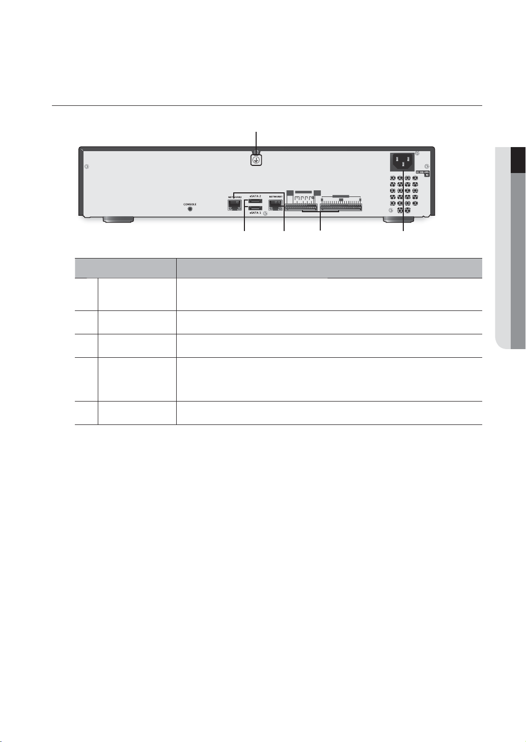
PART NAMES AND FUNCTIONS (REAR)
NOT
USE
ALARM OUT
1234
COMCOM
NO NO
NC NONO
ALARM
RESET
G
G GG G
COMCOM
ALARM IN
12345678 9
● OVERVIEW
10 11 12 13 14 15 16
b
c
Part Names Functions
b
c
Ground
eSATA 1/2
NETWORK 1/2
Port to connect a separate earth-grounding cable.
` Add a separate earth-grounding cable to use your product safely.
Ports used for external storage device connections.
NETWORK connector port.
- ALARM IN : Alarm input ports.
ALARM
- ALARM RESET : Alarm Reset port
- ALARM OUT : Alarm output ports.
Power
` [CONSOLE] is designed for the service repair purpose only.
M
Power connection port.
English _11
Page 12
installation
Please take note of the followings before using this product.
• Do not use the product outdoor.
• Do not spill water or liquid in the connection part of the product.
• Do not impose the system to excessive shock or force.
• Do not pull out the power plug forcefully.
• Do not disassemble the product on your own.
• Do not exceed the rated input/output range.
• Use a certified power cord only.
• For the product with an input ground, use a grounded power plug.
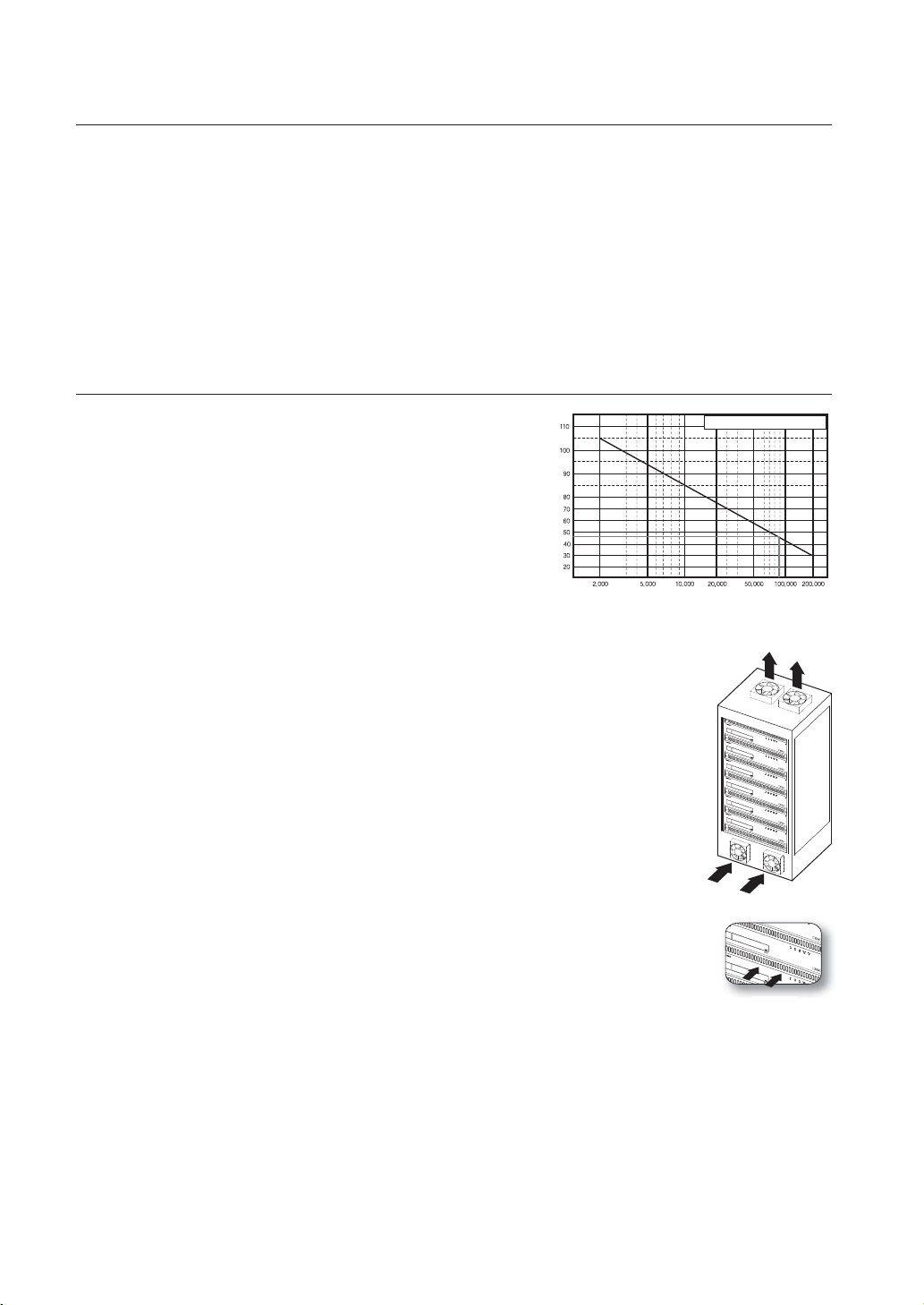
CHECKING THE INSTALLATION ENVIRONMENT
This product is a top-notch security device that is equipped
with a high-capacity HDD and other key circuit boards.
Note that an excessive internal temperature of the product may
cause a system failure or a shortened product life (see the right
figure). Keep in mind the following instructions before installing
the product.
When mounting the product on a rack, comply with the following instructions.
1. Please ensure that the rack inside is not sealed.
2. Please ensure the air is circulated through the inlet/outlet as shown in the picture.
3. If you pile up the prudcts or other rack-mount devices as shown in figure 2, secure room for
ventilation or install a vent.
4. For natural air convection, place the inlet at the bottom of the rack and the outlet on top.
5. It is strongly recommended that a fan motor is installed at the inlet and the outlet for air
circulation. (Please fit a filter at the inlet to screen dust or foreign substances.)
6. Please maintain the temperature inside the rack or surrounding areas between 0°C ~ 40°C
(32°F ~ 104°F) as shown in the figure 1.
Rack Mount Instructions - The following or similar rack-mount instructions are included
with the installation instructions :
A) Elevated Operating Ambient - If installed in a closed or multi-unit rack assembly, the
operating ambient temperature of the rack environment may be greater than room
ambient. Therefore, consideration should be given to installing the equipment in an
environment compatible with the maximum ambient temperature (Tma) specified by the
manufacturer.
B) Reduced Air Flow - Installation of the equipment in a rack should be such that the amount of air flow required
for safe operation of the equipment is not compromised.
C) Mechanical Loading - Mounting of the equipment in the rack should be such that a hazardous condition is
not achieved due to uneven mechanical loading.
D) Circuit Overloading - Consideration should be given to the connection of the equipment to the supply circuit
and the effect that overloading of the circuits might have on overcurrent protection and supply wiring.
Appropriate consideration of equipment nameplate ratings should be used when addressing this concern.
E) Reliable Earthing - Reliable earthing of rack-mounted equipment should be maintained. Particular attention should
be given to supply connections other than direct connections to the branch circuit (e.g. use of power strips).
Temperature
Unit: ºC
One Year: 24HR X 365 DAY =8,760 HR
Life (Unit: HOURS)
[Figure 1]
[Figure 2]
12_ installation
Page 13

RACK INSTALLATION
Install the Bracket-Rack as shown in the figure, and then fasten the
screws on both sides (2 screws on each side).
` Fix the screws not to be loosened by vibrations.
HDD ADDITION
Make sure to unplug the power cord from the wall outlet to prevent possible electric shock, injury or product damage.
Please consult your provider for further information on HDD installation since improper installation or settings may
damage the product.
` Number of HDDs supported : Up to 8
` Make sure to unplug the power cord from the wall outlet before proceeding with the installation.
` HDD-equipped model is installed with one HDD when shipped.
` Cautions for data loss (HDD care)
J
Please pay attention so that the data inside the HDD is not damaged.
Before adding a HDD, please check the compatibility with this product.
HDD is vulnerable to malfunction due to its sensitive nature especially against shock when operating.
Please ensure that the HDD is free from such shock.
We are not liable for any damage to the HDD incurred by user's carelessness or miss use.
` Cases might cause damage to HDD or recorded data
To minimize the risk of data loss from a damaged HDD, please backup data as often as possible.
If exposed to shock when disassembling or installing, data stored in the hard disk may be damaged.
A sudden power failure or turning off the product while in HDD operation may damage the hard disk drive.
HDD or files stored inside may be damaged if the main body is moved or impacted during the HDD operation.
● INSTALLATION
Cautions when installing a HDD
1. When adding a HDD, ensure that the cable does not get caught or the insulation does not come off.
2. Pay attention so as not to lose the disassembly screws or accessories.
` If the screws or accessories are not put together correctly, the product may breakdown or not operate properly.
3. Please check the HDD compatibility before adding a HDD.
` Please contact your nearest dealer to obtain the list of compatible devices.
English _13
Page 14

installation
1. First, loosen the screws on both sides and remove
the cover.
2. Loosen the screws (x4) in the left/right and upper
sides and remove the upper brackets.
Cover
Upper
Bracket
Lower Bracket
3. Install HDDs (x
with screws.
4.
Install HDDs (x4) on the upper bracket and fix them
with screws.
4) on the lower bracket and fix them
Upper
Bracket
Lower
Bracket
14_ installation
Page 15

5. When the installation of additional HDDs is done,
insert the lower and upper brackets into the NVR and
fix them with the provided screws.
6. When adding a HDD is completed, plug the power
cable and connect the SATA cable (for transferring the
HDD signal) to the connector
~ 8 of the main
board.
` Note that the order the HDD data cable is connected will not
affect the operation. The only consideration is the length of
each cable.
● INSTALLATION
8
7
7. Check if the connectors are properly connected and
there is no problem with wiring, and close the cover
and fix it with screws.
Cover
English _15
Page 16

connecting with other device
NOT
USE
ALARM
RESET
ALARM OUT
NO NO
COMCOM
1
2
3
4
123
4
5
6
78 9
10
11
12
1314
15
16
COM
COM
NC
NO
NO
G
ALARM IN
G
G
G
G
CONNECTING TO AN EXTERNAL DEVICE
eSATA HDD
Alarm
Sensors
Power
` Unrated or improper power source may cause damage to the system. Ensure that you use only the rated power source
J
before pressing the POWER button.
Connecting External eSATA HDD
External eSATA ports are provided on the rear panel by factory default.
If connected to the system, the external eSATA HDD can be recognized and configured in "Menu Setup >
Device > Storage Device".
` Use a cable shorter than 1m for the external eSATA HDD connections.
J
` The power for an external eSATA storage will be supplied separately.
` Unexpected disconnection to a device in use which is connected via eSATA may restart the system. Check whether the
device is in use before disconnecting it.
16_ connecting with other device
Page 17

Connecting the Alarm Input/Output
The Alarm In/Out port at the back is composed of the following.
• ALARM IN 1 ~ 16 : Alarm Input Port
• ALARM RESET : On receiving an Alarm Reset signal, the system cancels the current Alarm Input and
resumes sensing.
• ALARM OUT 1 ~ 4 : Alarm Output Port
● CONNECTING WITH OTHER DEVICE
ALARM OUT
(
30VDC 2A,
125VAC 0.5A MAX
ALARM IN
(
)
5mA sink
)
ALARM IN
(
5mA sink
)
English _17
Page 18

connecting with other device
NOT
USE
ALARM
RESET
ALARM OUT
NO NO
COM
COM
1
2
3
4
1
2
3
4
5
6
7
8
9
10
11
12
13
14
15
16
COMCOM
NC
NO
NO
G
ALARM IN
G
G
G
G
NOT
USE
ALARM
RESET
ALARM OUT
NO NO
COM
COM
1
2
3
4
1
2
3
4
5
6
7
8
9
1011
12
13
14
15
16
COMCOM
NC
NONO
G
ALARM IN
G
G
G
G
CONNECTING THE NETWORK
` For more information about network connection, refer to "Network Configuration". (Page 76)
M
Network connection via Ethernet (10/100/1000BaseT)
Switch
Network
Camera
Network
Camera
Network connection via router
Network
Camera
Network
Camera
xDSL or Cable
Modem
Switch
Switch
Windows
Network Viewer
Brodband router
NETWORK
xDSL or Cable
Modem
Windows
Network Viewer
18_ connecting with other device
DDNS
(Data Center)
Page 19
Connecting to network through PPPoE
NOT
USE
ALARM
RESET
ALARM OUT
NO NO
COM
COM
1
2
3
4
1
2
3
4
5
6
7
8
9
10
11
12
13
14
15
16
COMCOM
NC
NONO
G
ALARM IN
G
G
G
G
ex) IP : 192
.168.2
.100
ex) IP
: 192.168.1.1
00
NOT
USE
ALARM
RESET
ALARM OUT
NO
NO
COMCOM
1
23
4
1
2
3
4
5
6
7
8
9
10
11
12
13
1415
16
COM
COM
NC
NO
NO
G
ALARM IN
G
G
G
G
● CONNECTING WITH OTHER DEVICE
Switch
Network
Camera
Network
Camera
Windows
Network Viewer
Connecting the network camera
Switch
ADSL MODEM
Switch
ex) IP : 192.168.2.100
Phone(PPPoE)
Line
ex) IP : 192.168.1.100
NETWORK
Network Camera
ex) IP : 192.168.2.10
Network Camera
Switch
ex) IP : 192.168.2.20
Network Camera
ex) IP : 192.168.1.20
Network Camera
ex) IP : 192.168.1.10
` You can connect the camera or network viewer to either [NETWORK1] or [NETWORK2] to your preference.
M
` Use a Giga-bit switch for network connection switch.
English _19
Page 20

connecting with other device
NETWORKING WITH IP INSTALLER
Use provided IP Installer application program to search devices on the network and manually change the network
settings of the searched device.
Buttons used in IP Installer
b
b
c
Item Description
Device Type
Device Name
Select a device type to search.
Model name of the connected device.
Click the column to sort the list by model name.
However, search will be stopped if clicked during the search.
m
n
Alias
c
Mode
MAC Address
IP Address
20_ connecting with other device
Shows the NVR name specified by the Device Name in the <System Manage>.
Displays either <Static>, <Dynamic> or <PPPoE> for the current network connection status.
MAC Address for the connected device.
Click the column to sort the list by MAC Address.
However, search will be stopped if clicked during the search.
IP address of selected device.
Click the column to sort the list by IP address.
However, search will be stopped if clicked during the search.
Page 21

Item Description
Network setting for the device.
Protocol
The factory default is “IPv4”.
Devices with the IPv6 setting will be displayed “IPv6”.
● CONNECTING WITH OTHER DEVICE
URL
IPv4
IPv6
Search
Auto Set
Manual Set
m
Exit
n
` For the IP installer, use only the installer version provided in the installation CD or use the latest one if available.
M
You can download the latest version from the Samsung web site (www.samsungcctv.com).
DDNS URL address enabling access from the external Internet.
However, this will be replaced with the <IP Address> of the device if DDNS registration has failed.
Scans for devices with the IPv4 setting.
Scans for devices with the IPv6 setting.
Scans for devices that are currently connected to the network.
However, this button will be grayed out if neither IPv4 nor IPv6 is checked.
The IP Installer automatically configures the network settings.
You should configure the network settings manually.
Exits the IP Installer program.
Static IP Setup
Manual Network Setup
Run <IP Installer_vX.XX.exe> to display the device search list.
At the initial startup, both [Auto Set] and [Manual Set] will be grayed out.
1. Select a NVR in the search list.
Both the [Auto Set] and [Manual Set] buttons will be
activated.
2. Click [Manual Set].
The Manual Setting dialog appears.
The default values of <IP Address>, <Subnet Mask>,
<Gateway>, <HTTP Port> and <Port(TCP)> of the NVR
will be displayed.
` If found multiple devices assigned with the same IP address, assign different IP addresses to such devices to avoid conflict.
J
` If conflict has been occurred by sharing the same IP address by multiple devices, recovering may take some time.
3. In the <Address> pane, provide the necessary information.
• MAC (Ethernet) Address : The MAC (Ethernet) address of
the applicable NVR will be set automatically so you don't
need to input it manually.
` You can configure the static IP settings only if the DHCP checkbox
M
is unchecked.
English _21
Page 22

connecting with other device
If not using a Broadband Router
For setting <IP Address>, <Subnet Mask>, and <Gateway>, contact your network administrator.
4. In the <Port> pane, provide necessary information.
• HTTP Port : Used to access the NVR using the Internet browser, defaulted to 80.
Use the spin button to change the HTTP Port value.
• Port(TCP) : Used to control the video signal transfer, defaulted to 554.
5. Enter the password.
This is the login password for the “admin” user who accesses the NVR.
The default password is “4321”.
` The default password can be exposed to a hacking thread so it is recommended to change the password after installing the
J
product.
` Note that the security and other related issues caused by the unchanged password shall be responsible for the user.
6. Click [OK].
Manual network setup will be completed.
If using a Broadband Router
• IP Address : Enter an address falling in the IP range provided
by the Broadband Router.
ex) 192.168.1.2~254, 192.168.0.2~254, 192.168.XXX.2~254
• Subnet Mask : The <Subnet Mask> of the Broadband
Router will be the <Subnet Mask> of the NVR.
• Gateway : The <Local IP Address> of the Broadband Router
will be the <Gateway> of the NVR.
` The settings may differ depending on the connected Broadband
M
Router model.
For more information, refer to the user manual of the applicable router.
` Refer to the “Port Range Forward (Port Mapping) Setup” section of the Broadband Router’s documentation. (Page 24)
Auto Network Setup
Run <IP Installer_vX.XX.exe> to display the device search list.
At the initial startup, both [Auto Set] and [Manual Set] will be grayed out.
1. Select a NVR in the search list.
Both the [Auto Set] and [Manual Set] buttons will be activated.
2. Click [Auto Set].
The Auto Setting dialog appears.
The <IP Address>, <Subnet Mask>, and <Gateway> will be set automatically.
22_ connecting with other device
Page 23

3. Enter the password.
This is the login password for the “admin” user who
accesses the NVR. The default password is “4321”.
` The default password can be exposed to a hacking thread so it is
M
recommended to change the password after installing the product.
` Note that the security and other related issues caused by the
unchanged password shall be responsible for the user.
4. Click [OK].
Auto network setup will be completed.
Dynamic IP Setup
Dynamic IP Environment Setup
• Example of the Dynamic IP environment
- If a Broadband Router, with NVRs connected, is assigned an IP address by the DHCP server
- If connecting the NVR directly to modem using the DHCP protocols
- If IPs are assigned by the internal DHCP server via the LAN
Checking the Dynamic IP
1. Run the IP Installer on the user’s local machine to display
device allocated with <Dynamic> IP addresses in the list.
2. Select a NVRs in the list, and click [Manual Set] to check
the <Dynamic> IP of the NVR.
If you uncheck <DHCP>, you can change IP to <Static>.
● CONNECTING WITH OTHER DEVICE
English _23
Page 24

connecting with other device
PORT RANGE FORWARD (PORT MAPPING) SETUP
If you have installed a Broadband Router with a NVR connected, you must set the port range forwarding on the
Broadband Router so that a remote PC can access the camera in it.
Manual Port Range Forwarding
1. Broadband Router, select <Applications & Gaming>
- <Port Range Forward>.
For setting the port range forward for a third-party
Broadband Router, refer to the user guide of that
Broadband Router.
2. Select <TCP> and <UDP Port> for each connected NVR's
to the Broadband Router.
Each port number for the Broadband Router should match
that specified in <Network>-<Interface>-<Port> from the
NVR's Setup menu.
3. When done, click [Save Settings].
Your settings will be saved.
` Above sample instructions are based on the CISCO’s Broadband
M
Router.
` The settings may differ depending on the connected Broadband Router model.
For more information, refer to the user manual of the applicable router.
CONNECTING TO THE NVR FROM A SHARED LOCAL PC USING IP
INSTALLER
1. Run the IP Installer.
It will scan for connected NVRs and display them as a list.
2. Double-click a NVR to access.
The Internet browser starts and connects to the NVR.
` Access to the NVR can also be gained by typing the NVR's IP
M
address in the address bar of the Internet browser.
CONNECTING TO THE NVR FROM A REMOTE PC VIA THE INTERNET
Since using the IP Installer on a remote computer that is not in the Broadband Router’s network cluster is not allowed,
users can access NVRs within a Broadband Router’s network by using the NVR's DDNS URL.
1. Before you can access a NVR in the Broadband Router network, you should have set the port range
forward for the Broadband Router.
2. From the remote PC, launch the Internet browser and type the DDNS URL address of the NVR, or the IP
address of the Broadband Router in the address bar.
ex) http://www.samsungipolis.com/[Product ID]
24_ connecting with other device
Page 25

starting web viewer
WHAT IS WEB VIEWER?
The Web Viewer is a remote monitoring viewer that allows you to access the NVR and control real-time monitoring,
PTZ control (if configured), searching, etc.
NETWORK
● STARTING WEB VIEWER
Network Camera
REC HDD ALARM NETWORK POWER
NVR
NETWORK
Remote PC
Product Features
• Remote connection using the browser
• PTZ camera control enabled
• Supports 1, 4, 9, 16 camera viewing formats (maximum of 64 cameras in the list).
• Saving function in JPEG/BMP image format for printing and storage.
• Record video in AVI format-compatible with popular media players. (The integrated codec is needed)
System Requirements
The following lists the minimum suggested hardware and operating system requirements needed to run the
Web Viewer.
Item Minimum Recommended
CPU Intel Core 2 Quad 2.5GHz or higher Intel i7 or more
RAM 3GB or more 3GB or more
HDD 200GB or more 200GB or more
VGA Memory 512MB or more 1GB or more
Display Resolution 1280 x 1024 or higher
Windows XP Professional, Windows Vista Home Basic/Premium/Ultimate, Windows 7 DirectX
OS
Network 10/100/1000 Ethernet NIC
9.0c (Uses Direct3D Acceleration)
Internet Explorer 7, 8, 9 (Internet Explorer x86 in Windows 7 64-bit environment)
English _25
Page 26

starting web viewer
STARTING THE SYSTEM
1. Connect the power cable of the NVR to the wall outlet.
2. It turns on with a beep.
3. Open the web browser and enter the NVR’s IP address or
URL in address field.
4. You will see the initialization screen.
The initialization process will last about 2 minute.
If a new HDD is installed, the initialization process may take
longer.
` The LED allows you to check the system operating status at each
M
level.
You can recognize that the booting process is completed when the
<ALARM> and <REC> LEDs turn on in order and blink together.
` The NVR runs automatically when conneced the power cable.
5. Once completed the booting process, the login window appears.
Setting the Internet Explorer Options
Check the following options in the Internet Explorer before
starting the Web Viewer to have correct data transferred from
the NVR.
` “Internet Options > General tab > Settings (Browsing history)
M
> Temporary Internet Files > Check for newer versions of
stored pages:”
You should set the above items whenever opening a page.
` For ensuring proper operation and better security of your
J
computer’s Windows / Internet Explorer, update your operating
system and Internet Explorer to the latest.
26_ starting web viewer
Page 27

CONNECTING WEB VIEWER
1. Open your web browser and type the IP address or URL of
NVR into the URL address box.
` “192.168.1.200” is set to IP by default.
M
` Set to an available IP address in IP Installer or "Network >
Connection Mode”.
` The URL connection will be enabled only when the DDNS connection settings have been completed.
2. A user with the admin permissions should provide the admin
ID and password. A registered user should provide the user
ID and password.
` The default password can be exposed to a hacking thread so it is
J
recommended to change the password after installing the product.
` Set password for your wireless network if you use the product with a wireless router. Being not protected with password or
using the default wireless router password may expose your video data to potential threat.
` Note that the security and other related issues caused by the unchanged password shall be responsible for the user.
` It allow s up to 10 simultaneous access including the Admin and general users.
M
` It does not allow multiple login of the Admin user.
` The default ID of the admin account is “admin”, and the default password is “4321”.
` Password of the Admin and general users can be changed in <Permission Management> menu of the NVR.
` All settings are applied by the NVR’s settings.
● STARTING WEB VIEWER
3. Click <Install ActiveX Control...>.
4. When the installation confirm message appear, click [Yes]
button.
English _27
Page 28

starting web viewer
5. When a program installation wizard window appears, press
the [Install] button to install the program.
6. Open the Web Viewer after installing software, and log in
again.
Live Viewer's main screen appears when you log in
successfully after installing the program.
If using more than 2 Web Viewer in the same PC
If you open a new Web Viewer while operating a Web Viewer in Internet Explorer, the user may be switched into
the newly logged in user. In this case, you can open a separate window in a new session. Then, you can open
a new window without applying the Session Cookie without changing the accessing account.
• Internet Explorer 7, 8, 9 : After logging in and activating the
Web Viewer, if you run another Web Viewer on a new tab or
on a separate explorer instance, you are requested to log in
again and the account used for new instance replaces former
login account for the previous Web Viewer instance.
• Internet Explorer 8, 9 : Click “File > New Session” to open a
new Web Viewer window with a separate login account other
than the one currently using.
` Terminology
M
- Cookie : The information used from logging in a web page until closing the page.
- Session : The information used from logging in a web page until closing the page.
- Session Cookie : Usually called as session. A cookie is stored in the user’s computer and maintains its information,
while the session cookie is to be expired once its communication session expires In general, it is frequently used for
logging in and transmitting relatively important cookie data as encrypted.
28_ starting web viewer
Page 29

Differences on Using the Web Viewer By User Permissions
When running the Internet Explorer in Windows Vista or 7, you can run the Web Viewer with administrator
permission. You have different permission range depending on which permission you use between user and
administrator.
When Running the Internet Explorer as an Administrator
• You can modify file-saving path when using the Capture
function in Live or Search menu. In addition, you can save the
file in BMP, JPG, or PNG format.
• You can set the saving path when saving a video in AVI format.
• You can use the <Export> function when using “Settings >
Export” function.
When Running the Internet Explorer as a User
1. If the UAC is not operating
- You cannot modify the file-saving path when using the Capture function in Live or Search menu. The file
can be saved in BMP format.
- You cannot set the saving path when saving a video in AVI format.
- You can use the <Export> function when using “Settings > Export” function.
2. If the UAC is operating
- A warning message appears to request the user to run the Internet Explorer as an administrator when
attempting to use Capture function in Live or Search menu.
- A warning message appears to ask the user to run the Internet Explorer as an administrator when
attempting to save a video in AVI format.
- A warning message appears to request the user to run the Internet Explorer as an administrator when
using “Settings > Export” function.
● STARTING WEB VIEWER
What is User Account Control (UAC)?
User Account Control (UAC) is a security technology introduced with Microsoft's Windows Vista for the first
time It was also included in Windows Server 2008 and Windows 7. It aims to improve the security of operating
system by limiting rights on using application software to the standard user’s permission until an administrator
allows required permission.
English _29
Page 30

starting web viewer
To check the UAC operation
1. Select the Control Panel > User Account > Change User
Account Control settings.
2. Set the UAC setting by adjusting the slide button in the left.
To deactivate Pop-up Blocking
User may deactivate the Use pop-up blocker to use pop-up
window which notifies corresponding status while using the Web
Viewer.
In Internet Explorer, go to the <Privacy> tab in <Internet
Options>. And then deactivate the <Turn on Pop-up Blocker>
item.
30_ starting web viewer
Page 31

Checking Direct3D for Normal Operations of Web Viewer
Direct3D must be properly operating to view Live Viewer’s video.
1. Click Windows Start button located on the left side of the screen and open the Search Programs and Files
window. Enter “DxDiag” and press [Enter] key.
2. When Direct X Diagnostic Tool page starts, go to the second
tab, <Display> tab.
Set Direct3D Acceleration item in DirectX functions to
<Enabled> to use the Web Viewer normally.
3. If Direct3D Acceleration item is set to <Unavailable>,
reinstall the video card driver in your PC.
● STARTING WEB VIEWER
English _31
Page 32

live viewer
LIVE VIEWER
You can check the video from camera registered in the NVR connected from a remote PC. Also, you can adjust the
camera and check the network transfer status.
Live Viewer Screen
m
b
c
Menu Description
Menu Selection
Address, Name, Time
b
System Stauts Indicator
c
Split Mode Selection
Change Channel
Pause
Stop Alarm
Sound
Switches into corresponding menu screen by clicking each menu.
Displays the IP, model name, time, etc. of connected NVR.
Displays icons to display the screen or system status.
Selects the type of split screen and specify the channel displayed in Display Pane.
Switches into previous/next channel or perform Auto Sequence.
Click Auto Sequence button to display the Time Interval Selection menu.
Temporarily stops the videos in all the channels or deactivates the Pause function in
suspending status.
Deactivates an alarm when it occurs.
Sets the sound connected to each channel to ON/OFF.
32_ live viewer
Page 33

Menu Description
Capture
Print
Save as AVI
Manual NVR Record
PTZ
OSD menu
Live Status
Record Status
Display Pane
Shutdown
Logout
Saves current video for selected channel in designated path.
Prints current video image for selected channel through designated printer.
Records the live video in AVI file format in designated path, and then stops recording.
Recording status icon is displayed on screen during recording.
Manually activates and deactivates NVR recording.
Controls connect PTZ camera(s).
Goes to the relevant menu screen of a camera, which supports OSD menu and changes the
menu.
Displays corresponding live status of camea connected to each channel.
Displays corresponding record status of each channel.
Displays the video of camera connected to NVR.
Exits currently connecting NVR remotely.
A confirmation pops up to check if you surely want to close the NVR.
Performs logout process.
● LIVE VIEWER
m
ID
Displays the connected user ID.
English _33
Page 34

live viewer
LIVE SCREEN CONFIGURATION
System Status
You can check the status or operation of the NVR with the icons on the live screen.
CAM 01
Menu Description
Displayed if there is a problem with the cooling fan.
Displayed if the HDD needs a technical examination.
HDD
System
Operation
Record
Displayed if a new firmware is found from the network.
Displayed if no HDD is installed or the existing HDD should be replaced.
Displayed if the HDD is full and the NVR has an insufficient space to
record.
Appears when it is being recorded.
This is displayed if some channels will be recorded only on key frames
because the entire recording data size is over 100Mbps. (Page 70)
b
Video Input
b
34_ live viewer
Status
Appears when recording is limited due to network overload.
Displayed if you press the Pause button.
Displayed in Auto Sequence mode where all channels are switched at the specific time
interval.
Displayed if no input is entered in the condition that the camera is set to <ON>.
Displayed if no permission to live view is granted.
If your camera is turned <OFF> or in <Covert> mode, nothing is displayed on screen.
Page 35

Menu Description
b
Camera Title /
Channel
Video Input
Status
Display the camera title and channel number.
This icon is displayed for a channel that a PTZ-featuring camera is connected to.
Displays AUDIO ON/MUTE.
Not displayed in video mode if deactivated.
If the sensor is set to <ON>, the input signal will be displayed on the screen of the
connected channel.
Set the camera event detection to <ON>, and a camera event will be displayed when
occurred.
Displays the current record mode from Record/Event/Schedule.
Error Information
• If the internal HDD is not connected, the "NO HDD"( ) message will appear; if there occurs a problem, you
will see the "HDD FAIL"(
center for assistance as this may cause a failure of recording, playback or backup.
• If the cooling fan does not work properly or has a problem, the <Fan Information> window will appear and
the fan error icon (
works.
As a fan error can shorten the product life, make sure you contact the service center for assistance.
) message in the top left corner. In this case, make sure you contact the service
) will be displayed on the top left corner. In this case, check to see if the internal fan
● LIVE VIEWER
` If you see the fan error icon or NO HDD, HDD FAIL icons on the screen, contact the service center for more details.
M
` If NO HDD, HDD FAIL or fan error occurs, the front LEDs (ALARM, REC) keep blinking.
English _35
Page 36

live viewer
Registering the Camera
You should register your camera and save corresponding settings before watching the video of registered
camera in Live Viewer.
To register the camera
1. Click the <Setup> menu.
2. Click the <Device>-<Camera>-<Registration> menu.
3. Click the <Auto> in Device Registration window.
“Add Camera Automatically” window appears to list up the
available cameras which are present in network.
4. Click the camera(s) to register in the list.
5. Enter relevant <ID> and <Password> for the selected
camera(s).
6. Click the [Register] button.
` When registering multiple cameras selected in a batch, only cameras
set with the same user ID and password from the selected will be
registered.
7. When “Connection Test” confirmation window appears,
check the registration status and click [OK] button.
“Add Camera Automatically” window is closed and
registered camera(s) is(are) displayed in the list.
8. Click [OK] button to complete the registeration.
` For more detailed information about registering and removing
M
camera, refer to “To register a camera”. (Page 60)
36_ live viewer
Page 37

Changing Split Mode
When clicking the Split Mode selection button, the screen is
changed into the selected split mode.
To switch to Single screen mode
Click < >.
The monitor screen switches to the single screen of specified
camera among displayed channels.
It is also changed into Single screen if double-clicking your
desired camera channel.
You can go to the previous/next channel by clicking the
Previous/Next button.
To switch to QUAD screen mode
Click < >.
The screen mode switches to 4-split screen mode which
displays the channel group including currently specified camera.
● LIVE VIEWER
To switch to 9-split screen mode
Click < >.
The screen mode switches to 9-split screen mode which
displays the channel group including currently specified camera.
English _37
Page 38

live viewer
To switch to 16-split screen mode
Click < >.
The screen mode switches to 16-split screen mode which
displays the channel group including currently specified camera.
To go to your desired channel screen
Press the Previous/Next button to switch to the previous/next
channel group. Or click the channel selection bar next to Split
Mode buttons to select a desired channel in the drop-down
channel list.
To switch to full screen mode
Click < >.
Current split screen appears in full screen.
Press the [ESC] key to exit the full screen mode.
38_ live viewer
Page 39

Switching the split mode
You can play 64 live videos in sequence in Single, 4-split, 9-split, or 16-split Screen mode.
Auto Sequence
CH1
CH1
CH1
CH1
CH1
CH1
CH1
CH1
CH1
CH1
CH1
CH1
CH1
CH1
CH1
CH1
CH1
CH1
CH1
CH1
CH1
CH1
CH1
CH1
CH1
CH1
CH1
CH1
CH1
CH1
CH1
CH1
CH1
CH1
CH1
CH1
CH1
CH1
CH1
CH1
CH1
CH1
CH1
CH1
CH1
CH1
CH1
CH1
Single mode
CH1 CH3
CH1 CH3
CH1 CH3
CH4 CH5
CH2
CH1 CH3
CH4 CH5
CH2
CH1 CH3
CH4 CH5
CH7 CH8 CH9
CH4 CH5
CH7 CH8 CH9
CH4 CH5
CH7 CH8 CH9
CH7 CH8 CH9
CH7 CH8 CH9
9-split mode
1
CH2
CH1 CH3
CH2
CH1 CH3
CH2
CH1 CH3
CH4 CH5
CH2
CH4 CH5
CH2
CH4 CH5
CH2
CH7 CH8 CH9
CH6
CH7 CH8 CH9
CH6
CH7 CH8 CH9
CH6
CH6
CH6
1-9
● LIVE VIEWER
CH1 CH2
CH1 CH2
CH1 CH2
CH1 CH2
CH1
CH1
CH1
CH1
CH1
CH1
CH1
CH1
CH1
CH1
CH1
CH1
CH1
CH1
CH1
CH1
64
CH1 CH2
CH3 CH4
CH1 CH2
CH1 CH2
CH1 CH2
CH1 CH2
CH1 CH2
CH1 CH2
CH1 CH2
CH1 CH2
CH3 CH4
CH1 CH2
CH3 CH4
CH1 CH2
CH3 CH4
CH1 CH2
CH3 CH4
CH3 CH4
CH3 CH4
CH3 CH4
CH3 CH4
CH3 CH4
CH3 CH4
CH3 CH4
CH3 CH4
CH3 CH4
CH3 CH4
CH3 CH4
61-64
1-4
4-split mode
CH3
CH4
CH8
CH12
CH16
CH3
CH7
CH11
CH15
CH4
CH8
CH12
CH16
CH7
CH11
CH15
CH4
CH8
CH12
CH16
CH4
CH8
CH12
CH16
49-64
CH1
CH2
CH1
CH2
CH5
CH6
CH2
CH6
CH10
CH14
CH5
CH9
CH13
CH2
CH6
CH10
CH14
CH9
CH13
CH3
CH7
CH11
CH15
CH6
CH10
CH14
CH3
CH7
CH11
CH15
CH10
CH14
CH6
CH6
CH6
64
55-63
CH1
CH5
CH9
CH13
CH1
CH5
CH9
CH13
1-16
16-split mode
` When switching to another channel, the video may be slightly delayed depending on network status.
M
English _39
Page 40

live viewer
To switch to previous/next channel
Click < > or < > button.
You can go to the previous/next screen image of connected device in current split mode.
• Previous : Switches to the previous screen in reverse order.
• Next : Switches to the next screen in order.
If you press the <
Order of reversed switching in 16-split mode : CH 1~16 CH 49~64 CH 33~48 CH 17~32 channel groups.
> button in 16-split mode:
(CH 1 ~ 16)
• If you press the < > button in 16-split mode:
Order of forward switching in 16-split mode : CH 1~16 CH 17~32 CH 33~48 CH 49~64 channel groups.
(CH 49 ~ 64) (CH 33 ~ 48) (CH 17 ~ 32)
(CH 1 ~ 16)
(CH 17 ~ 32) (CH 33 ~ 48) (CH 49 ~ 64)
64-Channel NVR
64-Channel NVR
To activate Auto Sequence
1. Click [ ] button.
2. Enter the auto sequence interval.
3. Click [OK] button.
40_ live viewer
Page 41

To capture a screen
1. Click < > button.
When a pop-up window appears, select the saving path for
captured image.
2. Select the path and name the file. And then click the <Save>
button.
3. Save current camera’s video image as .bmp, .jpg or .png file.
` If the viewer is running without the administrator’s permission in
J
Windows Vista/7, you may not save the captured image as .bmp, .
jpg or .png file.
To print a screen
1. Click < > button.
2. Print current camera’s video image with the printer
connected to the PC operating the Web Viewer.
● LIVE VIEWER
To save as AVI
1. Click < > button.
When “AVI Setup” window appears, select the record saving
path and capacity.
2. Select a desired path, enter the maximum recording
capacity, and then click <OK>button.
` Save current channel’s video as .avi file.For playing a video clip, you
can use the free video player to play the video.
(ex: GOM Player, KM Player, etc.)
` After saving an AVI file, install the CODEC when playing it in Windows Media Player.
` However, the video may not played properly, depending on the CODEC compliance of the player.
At least 1GB of free space is required for recording.
` While recording current data in Web Viewer, you cannot select Split Mode buttons, switch to the previous/next screen, or
J
activate Auto Sequence function.
` If the viewer is running without the administrator’s permission in Windows Vista / 7, you may not change a folder when
saving a video as AVI file.
English _41
Page 42

live viewer
CONTROLLING A CONNECTED NETWORK CAMERA
Controlling PTZ
If PTZ camera is connected, the <PTZ> icon appears on screen. When selecting corresponding camera
channel, the PTZ tab is provided to allow you to control the PTZ.
Direction Adjustment
PT Speed
b
Preset
c
Swing
Group
b
c
Item Description
Adjusts the direction of a camera.
Adjusts the PAN, TILT reaction speed.
Sets the preset position for camera framing and moves to designated preset position when
selecting a desired preset.
Moves between the preset start point and end point.
Moves in the path specified by combining the preset, pattern and auto pan.
Tour
Trace
FOCUS
IRIS
ZOOM
42_ live viewer
Moves in the path specified by combining multiple groups.
Moves camera’s framing in the predefined path.
Adjusts the focus of the camera.
Adjusts image’s brightness by controling the camera’s iris.
Zooms in/out the image by controling camera’s zoom.
Page 43

To set a preset
1. Click < > button to display “Preset” window.
2. Click <
3. Enter the name of preset.
4. Use direction keys to adjust the direction which camera aims
at.
5. Click the <Record> button.
> to select a desired preset number.
To activate the preset
1. Click < > button to display “Preset” window.
2. Select a desired preset to activate from the list.
The camera’s framing moves to the preset position.
● LIVE VIEWER
To activate Swing(Auto-pan), Group(Scan), Tour and Trace(Pattern)
You can activate listed functions in the same manner as using a preset. For more information, refer to
corresponding user manul of applicable camera.
` Only selective functions of the camera can be supported, depending on camera.
M
English _43
Page 44

live viewer
Controlling OSD Menu
If connected network camera supports the OSD menu, press the < > to enter camera’s menu screen to
change its settings.
Item Description
Direction Adjustment
You can go to a desired menu.
b
ENTER
Camera Menu / Exit
b
` For more information about camera’s OSD menu, refer to corresponding user manul of each camera.
M
Selects a desired item.
You can use / stop camera’s OSD menu settings.
44_ live viewer
Page 45

Live Status
Select <Live Status> from the live screen menu to display
status and transfer information of connected camera to each
channel.
• Connection : Checks the connection status of registered
camera.
• IP : Checks camera’s IP address.
• Codec : Checks camera’s tansfer profile.
• Resolution : Checks camera’s profile resolution.
• Send Rate : Checks camera’s profile baud rate.
• Quality : Checks camera’s profile transfer video quality.
Record Status
Select <Record Status> from the live screen menu to display camera profile, input/recording frame rates,
input/limit/recording bps of each channel.
• Profile : Shows the video profile configured to each channel.
• Record Type : Displays the applied recording type.
You can set the recording type in <Record Setup>.
• Frame (fps) : Show the input/record frames per second for
each channel.
• Data (Mbps)
- Limit / Input / Record : Shows the amount of limit/input/
recording data for each channel.
- Input / Limit : Shows the data ratio of actual data
transferred from the camera and allowed maximum defined
by user.
• Current : Shows the recording status information of currently
transferred data.
• MAX : Shows recording information of the most biggest recording data out of configured standard and event
recordings.
• Refresh : Reloads the recording information.
• Recordable (Date/Time) : Displays the available recording date and time calculated with the remaining free
space.
● LIVE VIEWER
English _45
Page 46

search viewer
search viewer
SEARCH VIEWER
You can search and play the video record saved in NVR by accessing NVR remotely.
Search Viewer Screen
b
c
m
Menu Selection
Address, Name, Time
b
Sound
c
Split Mode Selection
Capture
Print
Save as AVI
NVR Record
Calendar
Item Description
Switches to the corresponding menu screen by clicking each menu.
Displays the IP, model name, time, etc. of connected NVR.
Sets the sound connected to each channel to ON/OFF.
Selects the type of split screen and selects the channel displayed in Display Pane.
Saves current video for selected channel in designated path.
Prints current video image for selected channel through designated printer.
Records and saves currently playing video image as AVI filie in designated path and then stops.
Activates and deactivates an NVR recording.
Displays the video-recorded date in blue and today in red. Click the date in blue color to display
the recorded video information in timeline.
46_ search viewer
Page 47

Item Description
m
Overlapping Data
Play Control
Recording Color
Display Pane
Shutdown
Logout
ID
Displays and zooms in/out recorded video data. If overlapping data found, this function selects
one of them to play.
Adjusts current video’s playback speed and played time position.
Displays the corresponding color depending on recorded data type if you place your mouse
cursor on that area.
Plays corresponding data on the screen if you select a search result.
Terminates currently connecting NVR remotely.
A confirmation pops up to check if you surely want to turn off the NVR.
Performs logout process.
Displays the connected user ID.
To search by date
You can select the search date by using calendar.
1. Click < > or < > to select the year to search.
2. Click <
The date including data appears in blue and today appears in red.
3. Click the date to search in calendar.
The first image of searched video data on the date is displayed on screen and the data is displayed in the
timeline.
4. To search video data on today, click <Today>.
Today’s date is selected.
> or < > to select the month to search.
● SEARCH VIEWER
Color indications depending on current recording status
Displays the corresponding color according to the recorded data type.
` If 2 or more kinds of recording type are mixed for the same timeline, only the recording type with higher priority is displayed.
M
(Priority: Audio Detection > Video Analysis > Motion > Sensor > Schedule > Standard)
English _47
Page 48

search viewer
To adjust timeline
If searched data are overlapping, you can select a desired data, move its playback time point, and zoom in/out
the timeline.
1. Select the number of data to search if data is overlapping.
It appears only when data are overlapped and assigns <0> to the most recent data.
2. Click your desired time point to play on the timeline.
The playback start point is moved.
3. Click <+> / <-> to zoom in/out the zoom factor to display time.
4. To show the previous/next timeline in zoomed-in status, click <_> or <+> to go to the left or right.
Names and Functions of Play Buttons
Jump Backward 10min
Fast Backward
b
Step Backward
c
Step Forward
Fast Forward
Jump Forward 10min
Item Description
b
Moves backward by 10 minutes from the current playing point.
Plays in reverse at doubled speed. The playback speed is doubled up to x64 speed.
Moves backward by 1 second from current playing point.
Moves forward by 1 second from current playing point.
Plays at doubled speed. The playback speed is doubled up to x64 speed.
Moves forward by 10 minutes from the current playing point.
c
Go to First
Reverse Play
48_ search viewer
Moves to the recording start point on the corresponding timeline.
Plays in reverse.
Page 49

Item Description
Stop
Pause
Play
Go to Last
Stops playing. When resuming playback, it is played from the recording start point.
Pauses playing. When resuming playback, it is played from the stopped point.
Plays normally.
Moves to the recording end point on the corresponding timeline.
● SEARCH VIEWER
English _49
Page 50

menu setup
SETTINGS
You can remotely configure the NVR on network.
Settings Screen
b
c
b
c
Item Description
Menu Selection
Parent Menu
Sub-Menu
Detailed Menu
OK
Cancel
Shutdown
Logout
ID
Click each menu to switch into corresponding menu screen.
Configure the settings or select a parent item to change the existing settings.
Among the sub-menus of selected parent menu, select a desired item to set.
Click desired item’s input field to change and enter a desired value.
Apply the modified settings.
Return to the previous settings without saving changes.
Exit currently connecting NVR remotely.
A confirmation pops up to check if you surely want to close the NVR.
Perform logout process.
Display the connected user ID.
50_ menu setup
Page 51

SYSTEM SETUP
You can setup Date/Time/Language, Permission, System Properties and Log.
Date/Time/Language
Setting the Date/Time/Language
You can check and setup the current Date/Time and time related properties, as well as the language used for
the interface on the screen.
• Date: Set the date displayed on screen.
• Time : Set the time displayed on screen.
• Time Zone : Sets the time zone of your area based on the Greenwich Mean Time (GMT).
` GMT (Greenwich Mean Time) is standard World Time and the basis of world time zone.
• Time Sync. : Specify the use of synchronization with the time server.
Click the <Setup> button to display Time Sync. Setup screen.
If you select to use the <Time Server>, the current time will be synchronized on a regular basis by the server
defined as <Time Server>.
If this is the case, you cannot change the time setting manually.
-
Synchronization : Specify the use of synchronization with the time server.
-
Time Server : Enter an IP or URL address of the time server.
-
Last Sync Time : Displays the most recent synchronization time from the selected time server.
-
Activate as Server : Set to <Use> to allow the NVR to act as a Time Server for other NVRs.
● MENU SETUP
` On the right side of the Time Synchronization item, specify whether to apply time synchronization.
M
• Display : Select date and time display format.
• DST : Set up Daylight Saving Time with its period to make the time earlier than the GMT of its time zone by
1 hour during the set period.
• Language : Select your language. Sets the language for the interface.
English, French, German, Spanish, Italian, Chinese, Russian, Korean, Polish, Japanese, Dutch, Portuguese,
Turkish, Czech, Danish, Swedish, Thai, Romanian, Serbian, Croatian, Hungarian
Norwegian are available.
, Greek, Finnish and
English _51
Page 52

menu setup
Setting Holiday
You can set specific dates to Holidays according to your preferences.
Holidays are applied to <Recording Schedule> and <Alarm Out Schedule> too.
` Ex : Select January 10th and check on <1/10> only to make every January 10th a holiday. Check both on <1/10> and <Jan 2nd
Tue > to make every January 10th and 2nd Tuesday of January holidays.
` Date set as holiday appears in yellow color.
To select date
1. Click < > or < > to select the year to search.
2. Click <
> or < > to select the month to search.
Permission Management
You can set permissions of each user over the NVR's specific function and settings.
Setting the Administrator
You can set and change Administrator's ID and password.
The administrator can use and set all menu items and functions.
52_ menu setup
Page 53

•
ID : Change the admin ID.
•
Password : Provide a new password.
` The default ID is "admin"; the default password is "4321".
M
` ID allows alphanumeric characters only.
` For the password, use alphabets and special characters excluding < \ > and <">.
` The default password can be exposed to a hacking thread so it is recommended to change the password after installing the
product.
Note that the security and other related issues caused by the unchanged password shall be responsible for the user.
Setting the Group
You can create user groups and setup permissions for those user groups.
You can register a user for each group in <User>.
● MENU SETUP
•
Add, Delete, Rename : You can add, delete, rename a group or modify the permissions given to the group.
The virtual keyboard appears when <Add> or <Rename> was selected.
You can add up to 10 groups.
-
Add : Provide a name for the group that you want to add. You can add up to 10 groups.
When you first start the NVR, the admin is the only user account so any other button than Add will be
deactivated.
-
Delete : Deletes a user group that is already registered. Selecting Delete will delete all user accounts
belonging to that group.
-
Rename : Renames a group that is already registered. Select <Rename> to display the virtual keyboard.
•
Group Authority : Sets permissions to access menu items of each group.
Users of a group can access checked functions.
English _53
Page 54

menu setup
To set the group authority
You can set the permissions of the group users to access the menu according to the channel.
1. Select a menu to which the group permission is assigned.
The menu where the group permission is assigned will be displayed in the Live menu when a group user
logs in.
•
Live View : You can set the permission to access the Live screen according to the channel.
Select the check box to pop up the “Channel Setup” window. Click desired channel’s check box to display
Live View.
•
Search : You can set the permission to access the Search menu according to the channel.
Select the check box to pop up the “Channel Setup” window. Click desired channel’s check box which is
available to search.
• Backup : You can set the permission to access the Backup menu according to the channel.
Select the check box to pop up the “Channel Setup” window. Click desired channel’s check box to back up.
Note that the Web Viewer itself does not provide its own backup function.
•
Menu : You can set menus accessible with a specific permission. Group users can access the permitted
menus only. Select a menu to display the Menu Permission screen.
•
Record Stop, PTZ, Remote Alarm Out, Shutdown : Select an item so that the item will be added to the
permissions.
2. Click <OK>.
Select and assign a group user so that the user can access the specified menu.
54_ menu setup
Page 55

Setting the users
You can add a user and edit information of a registered user.
To register a user
1. Select a user group.
You must first register a group where the user will belong to so that user can be registered. (Page 53)
2. Enter name, ID, and password.
3. Click <OK>.
Registered user information is displayed in the list.
To edit or delete user information
● MENU SETUP
1. Select an item in the user information displayed in the list.
2. Edit desired information(s) and click <OK>.
3. To delete the user information, click the Delete button displayed in the list.
4. When confirmation prompts, click <OK>.
English _55
Page 56

menu setup
Setting Permissions
You can set restricted access for all general users.
Items with restrictions will require logging in for use.
•
Restricted Access : All menu items allowed for a user can be set with restricted access.
-
Checked ( ) : Restricted
-
Not checked ( ) : Accessible
` If it is not checked ( ) in <Restricted Access>, any user can access the item no matter what the <Group Authority> setting.
` If it is checked ( ) in <Restricted Access>, a user can access the item only if the user has permission in <Group Authority>
setting.
If the user has restricted access
If a new group is restricted to access the entire menus, the users belonging to the group can access only the
basic menus and can change only their respective password.
If all permissions are restricted, you can only access to the menu buttons which are accessable on Live Viewer
screen.
To change password of a regular user with restricted permission
If you log in with the user account of a group with restricted access, you just can change your own password.
1. Provide the login information.
2. Click <Setup>.
The Permission Management screen appears.
3. Provide a new password.
4. Click <OK>.
The old password will be changed to a new one.
56_ menu setup
Page 57

System Manage
You can confirm the version of the current system, update its version to recent one, or initialize the settings.
Checking the System Information
You can check the current software version and MAC address before proceeding with the upgrade.
It is not allowed to edit each setting value.
•
Software Version : Shows the current Software Version information.
The values can not be changed by a user.
•
S/W Upgrade : Updates the NVR's software up to date.
• Server Upgrade : If upgradable file(s) is(are) available from the server, corresponding software is upgraded to
the most updated version.
• Micom Version : Displays the internal Micon version.
• Mac Address 1/ 2 : Displays the system Mac address.
•
Device Name : Displayed if the network viewer is connected to NVR.
● MENU SETUP
English _57
Page 58

menu setup
To upgrade the current software version
1. Prepare the software to upgrade.
` In case of server upgrade, NVR must be currently connected to the server in the network.
When a new firmware is available in the network, the corresponding icon appears to notify the update. (Page 34)
` If connected through a proxy server, it may not be upgradable due to limited access.
2. Select the <System Manage> in <System> window.
3. Select the <Upgrade>.
4. Select the prepared software and press OK.
` You can execute <Upgrade> function only when the <Version> of <S/W Upgrade> is higher than the <Software Version>
of <System Information>.
5. The screen changes according to each phase of upgrade.
6. The system restarts automatically after completing the upgrade.
Do not turn off the system power or disconnect the network until it is fully rebooted.
` Try again from step 3 when “Fail” window prompts.
M
Contact your service center if you fail continuously.
Settings
You can copy and import the NVR settings by using a storage media.
58_ menu setup
Page 59

•
Export : Exports NVR settings to the connected storage device.
•
Import : Imports NVR settings from the storage device and applies to the NVR.
-
Check checkboxes of items to be excluded from importing.
Only the other items than selected will be applied to the NVR.
•
Load Factory Default : Restore the factory default settings of NVR.
Check the checkbox of an item(s) that you want to reset. Then, only the other items than the selected one will
return to the factory default.
If <Default> is selected, a confirmation dialog for "Load Factory Default" prompts.
Press <OK> to initialize the system to the factory default.
Log Information
You can browse logs on the system and events.
Checking the system log
System Log shows log and timestamp on every system start up, system shutdown, and changes on system
settings.
● MENU SETUP
• Search Day : Click the Calendar button to select a desired search day.
• First Page : Goes to the first page of searched list.
• Last Page : Goes to the last page of searched list.
• CH : Select <All CHs> to scan all the channels. Or select a desired channel to scan a specific channel.
• Type : If there are a lot of log data, you can select desired log type to search for required contents easily.
• Export : You can export the log information in text file format.
•
: Enter your desired page number and press the < > button to go to corresponding page.
English _59
Page 60

menu setup
Checking the event log
You can search recorded events including alarms, camera events and video loss.
It also shows the log and its timestamp.
• Search Day : Click the Calendar button to select a desired search day.
• First Page : Goes to the first page of searched list.
• Last Page : Goes to the last page of searched list.
• CH : Select <All CHs> to scan all the channels. Or select a desired channel to scan a specific channel.
• Type : If there are a lot of log data, you can select desired log type to search for required contents easily.
•
: Enter your desired page number and press the < > button to go to corresponding page.
SETTING THE DEVICE
You can save relevant information in a camera or storage device.
Camera
To register a camera
You can register a network camera for each channel and make connection between.
•
Protocol : Show the protocol information of a registered network camera.
•
Model : Show the camera model name.
•
IP : Display the IP address of a network camera.
60_ menu setup
Page 61

•
Connection : Display the connection status.
•
Register : This is the default registration button for a network camera.
It will be displayed <Auto> before registration, and will be changed to <Delete> after registration.
• Data rate : Displays the total amount of data received from the channel.
• Performance : Displays the occupancy out of configured communication bandwidth for receiving the
corresponding data traffic.
Note that the cameras of RTSP and ONVIF protocols require about 2 times of data traffic to support control
traffic.
` If NVR is set to the defaul values, camera(s) may not be connected. So, set the network environment before registeration.
M
For more information, refer to "Network Configuration". (Page 76)
To auto-search for and register a network camera
1. Click the <Setup> menu.
2. Click the <Device>-<Camera>-<Registration> menu.
3. Click the <Auto> in Device Registration window.
“Add Camera Automatically” window appears to list up the available cameras present in the network.
` Press the <Refresh> button to check the changes of networked camera(s).
● MENU SETUP
4. Click the camera(s) to select from the list.
5. Enter relevant <ID> and <Password> for the selected camera(s).
6. Click the [Register] button.
` When registering multiple cameras selected in a batch, only cameras set with the same user ID and password from the selected
will be registered.
7. When “Connection Test” confirmation window appears, check the registration status and click [OK] button.
“Add Camera Automatically” window is closed and registered camera(s) is(are) displayed in the list.
8. Click [OK] button to complete the registeration.
` If <Performance> exceeds 100% of the system capacity, you cannot register a camera further.
` Since megapixel camera provides big sized video data, you should configure the number of concurrent monitoring accesses
M
and video settings appropriately considering your PC performance.
The followings are the recommended PC requirements for Web Viewer, which can be a configuration guide for H.264 video
monitoring.
- If monitoring 16 channels simultaneously with megapixel cameras whose resolution is set to 1280x1024 and size is set
to 5120Kbps (CBR), it is recommended to limit the maximum frame rate of each camera to 10fps.
- If monitoring 16 channels of megapixel cameras (at 1280x1024 and 2560Kbps(CBR)) and another 16 channels of 4CIF
cameras simultaneously, it is recommended to limit the maximum frame rate of each camera to 5fps.
English _61
Page 62

menu setup
To manually search for and register a network camera
1. Press <Add Manually> in the bottom left corner of the "Add Camera Automatically" window.
2. The Manual Search window appears.
3. Select a protocol.
The input items may differ depending on the selected protocol.
•
Samsung : Comply with the internal network protocols adopted by Samsung Techwin.
•
ONVIF : Means the camera supports ONVIF protocols. When connecting a camera that its name cannot be
found from the list, select <ONVIF>.
` Time difference between the ONVIF camera and NVR exceeds more than 2 minutes, the camera cannot be connected. In this
M
case, synchronize the ONVIF camera's time to the NVR or set times of both camera and NVR to a same NTP server (if in the
same time zone), or make the NVR an NTP server.
•
RTSP : Comply with RFC 2326, one of "Real Time Streaming Protocol (RTSP)" for real-time streaming.
4. If you select the <Samsung> protocol, check options as necessary.
•
Model : Select a camera model.
-
Samsung Network Camera/Encoder : Means the camera/encoder supports Samsung Techwin's SVNP
protocol. When connecting a camera that does not appear in the camera list, select Samsung Netowrk
Camera/Encoder.
` However, you must select the correct model name of the camera, if it's in the list. Some of obsolete camera models may not be
supported.
•
Address type : Select an address type of the camera.
` Address type can be different dependingon connected product model.
-
Static : Used to provide the IP address of the camera manually.
-
iPOLiS DDNS : This is available only if the camera is registered with the iPOLiS DDNS(www.samsungipolis.
com) server. Provide the registered domain for DDNS ID.
` Ex) http://www.samsungipolis.com/snb5000 -> provide "snb5000" for iPOLiS DDNS
-
MAC (Samsung) : Available if the camera supports the MAC Address-based DDNS.
-
URL : Used for URL address input.
` Refer to the user manual of the connected camera and check the DDNS specification that is supported by the camera.
M
62_ menu setup
Page 63

•
IP : Provide the IP address of the camera.
•
Device Port : Provide the device port of the camera.
•
HTTP Port : Provide the HTTP port of the camera.
•
ID : Provide the ID of the camera that you want to register.
•
Password : Enter the password of the camera to be registered.
5. Select <ONVIF> or <RTSP> for the protocol and enter your input for each field appears.
•
Target Service Address / RTSP URL : Enter the camera’s RTSP access address that supports ONVIF or RTSP.
For more information about the RTSP address, refer to the manual of each applicable network camera.
•
ID : Enter the ID for accessing via ONVIF/RTSP protocol.
•
Password : Enter the password for accessing via ONVIF/RTSP protocol.
•
Mode : Select a mode that is supported by the network camera in RTSP connection mode.
-
TCP : The connection type with the network camera will switch to "RTP over TCP".
-
UDP : The connection type with the network camera will switch to "RTP over UDP".
-
HTTP : The connection type with the network camera will switch to "RTP over TCP (HTTP)".
6. Click the <Register> button to register the selected camera.
● MENU SETUP
If you want to check the error details of camera registration
If you failed to register a camera, the reason for the failure will be displayed.
•
Connection failed due to unknown error. : This message appears if the camera has failed to be registered
due to unknown connection status.
•
Connected successfully. : This message appears if the camera is connected successfully.
•
Incorrect model information. Provide the correct model information. : This message appears if the
model information provided for registering the camera is incorrect.
•
Authentication has failed : This message appears if the ID or password provided for registering the camera
is incorrect.
•
Connection has failed due to excessive concurrent users. : This message appears if the concurrent user
count exceeds the upper limit.
•
Connection has failed due to incorrect HTTP port information. : This message appears if the HTTP port
number of the camera is invalid.
•
Connection has failed. Unknown connection status. : This message appears if the camera has failed to
be connected due to a unknown error.
•
User Model Modification : When registering a new camera, it is named according to the device’s default if
user set the model to <Samsung Network Camera/Encoder>. In case if automatic registration fails, user
can change the model name of camera to be registered.
English _63
Page 64

menu setup
To edit camera profile
When a camera is added for the first time, it is added as the default profile of H.264, MPEG4 and MJPEG in
order temporarily.
To change its profile, refer to "Setting the network camera’s recording profile" (Page 71) or "Live
Streaming" (Page 83).
`
In case of NVR, if you set 2 different profiles for live, recording and network profile, one camera will produce video streams
M
accordingly, having different stream formats. Especially, note that the live profile may vary depending on the used screen split mode.
` For cameras, if applied with one profile only, the produced frame rate is fixed as the profile specifies; if applied with multiple
profiles, produced video stream’s frame rate is not guaranteed. For example, if applied with 2 profiles of 30 fps, the camera
may transmit streams at 20fps.
To edit a registered camera
1. Click a camera to edit in the camera list.
2. Select the item to modify in “Edit Camera” window and modify its information.
3. When completed, click <Register> button.
To delete a registered camera
1. Select the camera to delete in the camera list and click <Delete>.
2. Click desired camera's check box in “Delete Camera” window.
Click <All> to delete all the cameras.
3. Click <OK> when selecting all desired camera(s).
64_ menu setup
Page 65

Camera Setting
You can change the video settings of a registered network camera for each channel.
• Select Camera : Select the camera number to change its settings.
• Profile : Displays video profile for connected camera settings.
• Codec : You cannot change the CODEC for selected profile.
• Resolution : You can change the resolution for selected profile.
• Send Rate : You can change the baud rate for selected profile.
• Quality : You can change the video quality for selected profile.
• Bitrate Control : You can change the bitrate setting of video transfer for the selected profile.
• Add : Add a camera profile.Click Add button to display the Add window.
Provide information and click <OK> button to add it to the list.
• Modify : Change the selected profile.
Select a profile and click <OK> button to display the Modify screen.
• Delete : Delete the selected profile from the list.
● MENU SETUP
` If you change the settings of a specific profile for each model, the effective range of the baud rate may be changed
M
accordingly.
Ex) if you set the baud rate of the first profile to 30fps, the send rate of the second profile will be changed to 15fps.
` Menu items except Codec, Resolution, Transfer Rate, and Transfer Quality can be configured in the network camera’s settings
menu.
` If you change the current profile settings, you may encounter an interrupted playback on the recording or live screen for a
certain time.
` Changes made in Camera Setup page are applied immediately, while changes made through the camera's web page may
require up to 3 minutes.
English _65
Page 66

menu setup
Channel Setting
You can configure the video settings for each channel.
•
Video
-
<ON/OFF> : You can turn ON/OFF the selected channel's camera.
-
<Covert> : Shows nothing but an empty screen while the recording continues.
` The channel whose video is set to <Covert> does not produce any sound.
M
However, the channel’s sound is recorded if its Audio setting is set to <ON>, even the sound is not heard in Live mode.
•
Audio
-
If set to <ON>, you can turn the audio of the channel ON/OFF on the Live screen.
-
If set to <OFF>, the channel's audio is off on the Live screen and not recorded.
•
Camera Name : Provide a camera Name.
` You can enter up to 15 characters including space.
Storage Device
You can check information on storage devices.
Confirming Devices
You can check storage devices and their free space, usage as well as status.
You can connect HDD.
66_ menu setup
Page 67

•
No. : Shows the assigned number of the internal HDD.
` To see the detailed positioning of the HDD according to the number, refer to <HDD Map>.
•
Used/Total : Shows the used/total capacity of the storage device.
•
Usage : Sets the storage device's usage.
` You can select the eSATA HDD for extended storage
` If disconnected an extended eSATA HDD storage device while operating, the system may restart.
J
•
Status/Management : Display the status of the storage device.
•
Temperature : You can check the temperature of HDD installed in NVR.
•
HDD Map : Shows the internal HDD's locations according to assigned numbers.
` Refer to this for servicing or additional HDD installation.
Formatting
You can format a storage device.
● MENU SETUP
• No. : Select the check box of the device to format.
•
Used/Total : Shows the used/total capacity of the storage device.
•
Usage : Sets the storage device's usage.
•
Format : Select a device and press this to display the format confirmation dialog.
Press <OK> to start formatting the selected storage device.
` Note that formatting the device will delete all of the existing recording data.
J
` Note that no recording is made during formatting is in progress.
` Do never remove the device to format until formatting is completed.
English _67
Page 68

menu setup
HDD Alarm Setting
You can set alarm settings for HDD defects such as Check Alarm Output Port, Replace Alarm Output Port, and
its duration.
•
Check Alarm Output Port : If HDD generates check alarm, the alarm signal will output to the specified alarm
output port.
•
Replace Alarm Output Port : If HDD generates replace alarm, the alarm signal will output to the specified
alarm output port.
•
Duration : Sets the alarm duration for the alarm signal and beep sound.
-
Check Alarm, Replace Alarm signals will output through the selected alarm out ports (1, 2, 3, and 4).
-
If <BEEP> was selected, a beep will sound.
-
If <All> was selected, both beep sound and alarm signal through rear side ports will output.
` <Check> status means that the HDD is operating but it has problems that require technical examination.
M
) appears on the Live screen.
(
` <Replace> status means that the HDD has defect and requires immediate replacement.
( ) appears on the Live screen.
68_ menu setup
Page 69

SETTING THE RECORDING
You can setup scheduled recording, event recording and other recording related settings.
Recording Schedule
Make your reservation on a date and time to schedule the recording on specified time.
• CH : Select the channel to configure scheduled recording.
•
All : The entire time range (Monday through Sunday including holidays, AM 0~ PM 23) will be reserved with
the same recording schedule
•
Apply to All : If selected <Apply to All>, "Apply to All" window appears.
Press <OK> to apply the setup to all channels.
` Event recording and scheduled recording starts about 3 seconds prior to the event/schedule for guaranteed recording.
M
Record setting by the color
Color Function Description
No Color No Recording No schedule / event recording
Green Continuous Scheduled recording only
Orange Event Event recording only
White Both(Cont&Evnt) Both scheduled / event recordings
● MENU SETUP
Each press of a selected cell will cycle through <No Recording>-<Continuous>-<Event>-<Both(Cont&Evnt)>.
To set the recording schedule
1. Click desired recording type to schedule from listed under the time setting cells.
The color of selected type changes into red.
2. Click the cell or drag desired area to schedule.
3. Click <OK> button to complete and apply the schedule.
English _69
Page 70

menu setup
Event Record Duration
You can set the beginning and ending point of a recording on an event.
•
Pre Event : The recording of an event will start at a pre-determined time prior to the actual occurrence of the event.
If it is set to 5 seconds, the recording begins from 5 seconds before the event.
•
POST Event : The recording will continue for a pre-determined time after the actual end of an event.
If it is set to 5 seconds, the recording ends in 5 seconds after an event.
` If the video resolution is larger than 4CIF, recording may not proceed as much as the pre-event recording time.
M
The greater the video data size is, the maximum pre-event recording time will be reduced in inverse proportion.
Record Setting
You can set resolution, IPS, and quality of recordings by channel, and by recording type of standard / event.
You can check frame rates and data transfer amount of Full Frame and Key Frame recordings for each channel,
and set the transfer limit for recordings.
Setting NVR Recording
•
Standard, Event : Configures Standard recording and Event recording.
-
Full Frame : Records all frames fed by the camera.
-
Key Frame : Records only key frames fed by the camera.
Actual recording rate may differ from camera settings. In general, 1 to 2 frames per second are recorded.
-
OFF : No recording is made.
70_ menu setup
Page 71

•
Full Frame : Shows the amount of received data for full frame recording.
•
Key Frame : Shows the amount of received data for key frame recording.
•
Bitrate Limit : Shows allowed maximum limit of data bitrate, per channel.
•
Audio : Specify whether to record the sound received from the camera or not.
•
: Displays corresponding recording status of each channel.
•
: Updates corresponding recording settings of each channel.
`
If a channel's data transfer exceeds defined allowed limit, then it may affect to other channels, and may force switching to
M
<Key Frame> recording even when the channel is configured to <Full Frame> recording mode. For Key Frame recording
channels, the icon for limited recording appears on the live screen's top side.
Press the <
reappear.
`
If a channel name is displayed in yellow, the camera profile of the channel is replaced with one other than assigned due to
problem.
Check the channel information to see the applied profile to the channel listed in yellow.
> button to make icon of limited recording disappear. If the transferred data exceeds the limit again, it will
Setting the network camera’s recording profile
You can configure the video profile settings for instructing the network camera (connected to each channel) to
make recording.
● MENU SETUP
` You can configure the settings only for the profiles that are supported by the camera.
M
` If the profiles used for recording and network are different, camera’s video feed may not comply with the frame rate as
specified in the camera.
•
Profile : Select a record profile for the connected camera.
•
Codec : Show the codec information for the selected record profile.
•
Resolution : Display the resolution for the selected record profile.
•
Send Rate : Display the baud rate for the selected record profile.
•
Quality : Display the video quality for the selected record profile.
English _71
Page 72

menu setup
Record Option
You can set the recording to stop or overwrite when the HDD is full.
•
Disk End Mode : Select a HDD repetitive recording type.
-
Overwrite : If the HDD is full, this will overwrite the existing data and keep recording.
-
Stop : If the HDD is full, this will stop recording automatically.
•
Disk End Beep : If you select <Stop> for the disk end mode, this button will be active. Specify the use of
beep when the HDD recording ends.
If you check it, the beep will sound on the disk full and the recording stops.
•
Auto Delete : If you check this option, the period list box is active. Specify the deletion period to delete any
earlier data than the specified date. However, you can search for data from the current time to the selected
date.
` If you press <OK> when you have completed your settings, all the existing data earlier than the specified period will be
J
deleted automatically. So it is recommend to backup the previous data if necessary for later use.
72_ menu setup
Page 73

SETTING THE EVENT
You can configure settings regarding event recordings of sensor, camera event and video loss event.
Sensor Detection
You can set the sensor's operating condition and connected camera, as well as alarm output and its duration.
Setting NVR Sensor Detection
•
Sensor Operation : Sets the operation mode of sensors.
-
<N.O (Normal Open)> : Sensor is opened. If the sensor is closed, it generates alarm.
-
<N.C (Normal Close)> : Sensor is closed. If the sensor is open, it generates alarm.
•
Cam : Select a channel to be connected to the sensor.
If selected camera, "Cam Preset setup" window appears.
Select a channel and setup the preset.
` Preset setup can be done in PTZ mode.
•
Alarm out : Sets the alarm output method.
` For further information on alarm output, refer to "HDD Alarm Setting". (Page 68)
● MENU SETUP
•
Duration : Sets the duration of alarm signal and alarm sound.
English _73
Page 74

menu setup
Setting Network Camera Sensor Detection
• Sensor Operation : Sets whether to operate the network camera sensor connected to each channel.
•
Cam : Select a channel to be connected to the sensor.
If selected camera, "Cam Preset setup" window appears.
Select a channel and setup the preset.
` Preset setup can be done in PTZ mode.
•
Alarm out : Sets the alarm output method.
` For further information on alarm output, refer to "HDD Alarm Setting". (Page 68)
•
Duration : Sets the duration of alarm signal and alarm sound.
` If the connected network camera that has configured the alarm in/out settings triggers an alarm, NVR will perform the alarm
M
out.
Camera Event
You can set whether to react to camera events (motion detection, video analysis, audio events) and alarm
output / time.
•
Mode : Select whether to react to camera events or not.
•
Alarm Out : Sets the alarm output method.
•
Duration : Sets the duration of alarm signal and alarm sound.
` The NVR generates alarm output only when the connected network camera is configured to detect events and an actual
M
event is detected.
74_ menu setup
Page 75

Video loss detection
You can set the camera so that the camera can trigger the alarm if it is disconnected or the video is lost due to
unstable network connection.
•
Video Loss State : Specify the use of video loss detection.
•
Alarm Out : Select an alarm output method.
•
Alarm Duration : Specify the duration of the alarm output with the beep.
Alarm Out Schedule
You can set the conditions and operating hours for scheduled alarms.
● MENU SETUP
•
Alarm Out : Sets the alarm output method.
` For further information on alarm output, refer to "HDD Alarm Setting". (Page 68)
-
<ON> : Marked in green, and always generates alarm on scheduled time.
-
<OFF> : Marked in black, no alarm is generated even if an event occurs.
-
<Event Sync> : Marked in orange, generates alarm only when an event occurs.
•
Apply to All : Applies the configured schedule to all alarms.
` For more information about how to set time, refer to “To set the recording schedule”. (Page 69)
` When the alarm is generated on the scheduled time, you can stop the alarm by canceling the schedule.
M
English _75
Page 76

menu setup
NETWORK CONFIGURATION
It provides networked monitoring of Live screen from a remote place, and supports mail forwarding function with
events. You can configure the network environment which enables such functions.
Interface
You can set the network connection route and protocol.
Network1/Network2 connection settings
Sets the protocol and environment of the network.
•
IP Type : Sets the network connection mode.
•
Network1 / Network2 Transfer Bandwidth : Enter the maximum amount of upload data bandwidth for each
network.
Check the assigned setting in Connection Mode before entering your value.
The maximum amount of network retransmission is limited to 64MB for both network1 and 2. Network1 is
set to use maximum bandwidth by default.
` Even though Network1 and Network2 are assigned with IP addresses from the same range, only the Network1 becomes
M
accessible if they are connected to physically different networks.
` Even when only one Ethernet port of Network1 and Network2 is connected to the network, both Network1 and 2 become
accessible if they are assigned with Static IP addresses in the same range.
•
IP Address, Subnet Mask, Gateway and DNS
-
For <Static> : You can directly input IP address, Gateway, Subnet Mask and DNS.
-
For <DHCP> : IP address, Gateway, and Subnet Mask are set automatically.
-
For <PPPoE> : IP address, Gateway, and Subnet Mask are set automatically.
•
ID, Password : In case you selected PPPoE, provide the "ID" and its "Password".
` DNS server for <DHCP> and <PPPoE> can be set by user only if you selected <Manual>.
M
` The data amount received by the Live Viewer is limited to the sum of all distributed data amount per channel, based on the
assigned total retransmission data amount.
Due to this reason, the actual received video data amount in live mode may be less than data transmission amount specified
in settings. To make the video look more smoothly, you can increase data traffic with bitrate setting and watch the video in a
single screen mode or in a split screen mode of a smaller number of channels.
76_ menu setup
Page 77

Setting the Network Connection without Router
•
Static
-
Internet connection : Static IP ADSL, leased line, and LAN environments allows connection between the
NVR and remote user.
-
NVR Network Settings : Set the <Interface> in <Network> menu of the connected NVR to <Static>.
` Consult your network manager for IP, Gateway and Subnet Mask.
•
DHCP
-
Internet connection : Connect the NVR directly to a cable modem, DHCP ADSL modem or FTTH network.
-
NVR Network Settings : Set the <Interface> in <Network> menu of the connected NVR to <DHCP>.
` If IP is not assigned within 1 minute, it is set to the previous static IP.
● MENU SETUP
•
PPPoE
-
Internet connection : An PPPoE modem is directly connected to the NVR, where the PPPoE connection
requires user ID and password.
-
NVR Network Settings : Set the <Interface> in <Network> menu of the connected NVR to <PPPoE>.
` PPPoE <ID> and <Password> should be the same to the PPPoE user information.
If you don't know the ID and password, consult your PPPoE service provider.
English _77
Page 78

menu setup
Setting the Network Connection Using Router
` To avoid IP address conflict with the NVR's static IP, check followings :
J
•
Setting the NVR with a static IP
-
Internet connection : You can connect the NVR to a router which is connected to an PPPoE/Cable modem
or a router in a Local Area Network (LAN) environment.
•
Setting the NVR Network
1. Set the <
2. Check whether the set IP address is in the static IP range provided by the Broadband Router.
IP,
3. Check the Gateway address and subnet mask are equal to those set in the Broadband Router.
•
Setting the DHCP IP Address of the Broadband Router
1. To access the Broadband Router's configurations, open a web browser on the local PC that is connected
to the Broadband Router and enter the router's address (ex : http://192.168.1.1).
2. At this stage, make the local PC's windows network configurations to the below example :
Ex) IP : 192.168.1.2
Interface> in <Network> menu of the connected NVR to <Static>.
Subnet Mask and Gateway : Consult your network manager.
` Check whether the set IP address is in the static IP range provided by the Broadband Router.
` If a DHCP server is configured with starting address (192.168.0.100) and end address (192.168.0.200), you should set the
J
IP address out of the configured DHCP range (192.168.0.2 ~ 192.168.0.99 and 192.168.0.201 ~ 192.168.0.254).
Subnet Mask : 255.255.255.0
Gateway : 192.168.1.1
-
Once connected to the Broadband Router, it prompts with password. While entering nothing to the User
Name field, enter "admin" into the password field and press <OK> to access the router configurations.
-
Access the router's DHCP configuration menu and set its DHCP server activation, and provide the start
and end address.
Set the start address (192.168.0.100) and end address (192.168.0.200).
` Above steps may differ from the router devices depending on the manufacturer.
M
78_ menu setup
Page 79

Setting Port
•
Protocol Type : Select the protocol type between TCP and UDP.
` If you select UDP, the items of UDP Port and Unicast/Multicast will be active.
` If set it to TCP, the Device Port item will be active.
•
Device Port : Enter the connectable port number. Initially, <554> is set.
-
TCP : It has better stability and lower speed when compared to UDP, and recommended for internet
environments.
•
UDP Port : Initially, <8000~8159> is set. It increases / decreases by 160.
-
UDP : It has less stability and faster speed when compared to TCP, and recommended for local area
network (LAN) environments.
•
Unicast/Multicast : Select one between Unicast and Multicast.
If selected Multicast, Multicast IP and TTL are activated.
-
Unicast : Transfers data (UDP, TCP) individually to each connecting client.
-
Multicast : Multiple client can receive the data (only in UDP) without putting additional traffic load to the
network.
•
Multicast IP Address : User can directly input.
•
Multicast TTL : Select from 0 ~ 255. Initial value for the TTL is set to <5>.
•
HTTP Port : Enter the port number for the Web Viewer. Initially, it is set to <80>.
● MENU SETUP
English _79
Page 80

menu setup
DDNS
You can set the DDNS site for a remote user's network connection.
•
DDNS Site : Specify the use of DDNS and select a site that you registered.
•
Host Name : Provide the host name that you registered with the DDNS site.
•
User Name : Provide the user ID that you registered with the DDNS Site.
•
Password : Provide the password that you registered with the DDNS site.
` If you select <OFF>, the input box will be inactive.
M
` If you select <samsungipolis.com>, the Server Name field is disabled.
•
Quick Connect : Appears if the <samsungipolis.com> is selected for a <DDNS Site>.
To use the function, set to <Use> after connecting the NVR to a UPnP router.
` If canceled during Quick Connect configuration, it automatically switches to <Not Used> and saved.
M
To check Quick Connect status
A progress bar and its message appears for a Quick Connect.
•
Quick Connect Success : Message for a successful connection.
•
Invalid Network Configuration : Message appears if the network configuration is not valid. Check the
configuration.
•
Please enable UPnP function of the router : Message appears if the router requires UPnP function
enabled.
•
Failed to find the router : Message appears if the router is not found. Check the router's configurations.
•
Please restart the router : Message appears if the router should be restarted.
•
The port is used by another device. : Please change the port number.
80_ menu setup
Page 81

DDNS Setting
DDNS is a short form of Dynamic Domain Naming System.
DNS (Domain Name System) is a service that routes a domain name consisting of user friendly characters
(ex : www.google.com) to an IP address consisting of numbers (64.233.189.104).
DDNS (Dynamic DNS) is a service that registers a domain name and the floating IP address with the DDNS
server so that the domain name can be routed to the IP address even if the IP is changed in a dynamic IP
system.
•
Setting DDNS in the NVR
Set <Protocol Type> in the <Protocol> menu of the connected NVR to the following :
Ex) Protocol Type : TCP
Device Port : 554 ~ 557
DDNS Site : iPOLiS
•
DDNS Settings of the Router
Select the corresponding menu for the network transfer protocol of the router.
•
Setting up UPnP of Router
Refer to the router's documentation to enable the UPnP function of the router.
IP Filtering
You can create a list of IPs that you want to grant or deny access to them.
● MENU SETUP
• Filtering Type :
-
Deny : Access from the IP(s), which is(are) added to the filtering, will be restricted.
-
Allow : Access from only IP(s) added to the filtering will be accepted.
• Use : Select the check box(es) of the IP(s) to use IP filtering.
• IP Address : Enter the IP address to filter.
• Filtering Range : If you enter the IP address and its Prefix, the range of allowed/denied IP addresses appears.
` If the camera’s IP is included in the Deny list or excluded in the Grant list, the access to the camera is blocked.
J
English _81
Page 82

menu setup
802.1x
When connecting to a network, you can select whether to use the 802.1x protocol and install corresponding
certificate.
802.1x is an authentication system between the server and client to protect the data transferred in network
from hacking, virus, leakage, etc.
By using the 802.1x authentication, unauthenticated client is blocked to access, only authenticated users are
allowed to communicate, and security is considerably improved.
• IEEE 802.1x : Specify the use of the 802.1x protocol.
• EAPOL Version : Select the EAPOL Version to use as a protocol.
` Some switch hubs may not work when Version <2> is selected. Select Version <1> for general cases.
• ID : Enter the ID provided by RADIUS server administrator.
` If your provided ID does not match with the ID in the client certificate, it is not processed properly.
• Password : Enter the password provided by RADIUS server administrator.
` If your provided password does not match with that of client’s private key, it is not processed properly.
• CA Certificates : Select if it is an authorized certificate including public key.
• Client Certificates : Select if it is an authorized certificate including client’s authentication key.
• Client Private Key : Select if it is an authorized certificate including client’s private key.
` To build a 802.1x environment, administrator should use RADIUS server.
M
Also, the switch hub connected to the server should support the 802.1x.
` The time settings in RADIUS server, switch hub, and NVR device must be synchronized. Otherwise, communication may be
blocked.
` If a password is assigned to the client's private key, server administrator should confirm the ID and password.
The ID and password allow up to 30 characters each. (However, only alphanumeric characters and “-”, “_”, “.” are allowed.)
Accessing files not locked with password is allowed without entering the password.
` The 802.1x protocol adopted by the NVR is EAP-TLS.
` All the 3 certificates must be installed to properly use the 802.1x environment.
82_ menu setup
Page 83

Live Streaming
You can configure the profile to transfer the live video of each channel via the network.
•
Profile : Select a network profile for the connected camera.
•
Codec : Show the codec information for the selected network profile.
•
Resolution : Display the resolution for the selected network profile.
•
Send Rate : Display the baud rate for the selected network profile.
•
Quality : Display the video quality for the selected network profile.
` If the profiles used for network and recording are different, camera’s video feed may not comply with the frame rate as
M
specified in the camera.
● MENU SETUP
E-mail
You can send an e-mail to a NVR-registered user at a specific time interval, or if an event occurs.
` If the camera is set to <OFF> or the channel’s event is Video Loss, a notification is sent to the designated email address only
M
in text.
SMTP Setting
Sets the SMTP mail server.
•
Server Address : Displays the connected server type.
•
Port : Sets the communication port.
English _83
Page 84

menu setup
•
Use Authentication : Check this if the SMTP server uses user authentication.
The account input box will be activated.
•
ID : Enter a user to use authentication when connecting to the SMTP server.
•
Password : Enter the password of the SMTP server user.
•
Secure Transfer : Select one from <Never> and <TLS (if available)>.
•
Sender Address : Use the virtual keyboard to enter the sender's e-mail address.
•
E-mail Test : Conducts the test on the server settings.
Event Setting
You can set the interval and type of the event that will be sent to the user.
•
Event Interval : Set the event interval.
` If a series of events occurs, the e-mail will be sent at the specified interval, not on each event.
•
Use Event Transfer : Select an event type to send if an event occurs.
If the selected event occurs, the e-mail will be sent to the group that has the recipient authority.
84_ menu setup
Page 85

Group Setting
You can set the group to whom the e-mail is sent, and specify the permission for each group.
Apart from the NVR user group, you can add email recipients from the <Recipient> item.
•
Group : Specify the recipient group who receives the email event notification.
-
Add : Click the button to display the added group name input dialog. Enter the name, and click <OK> to
add the group.
-
Delete : Deletes the selected group.
-
Rename : You can reset the recipient permission of an existing group.
•
Recipient Permission : Set the permission of the recipient group.
Recipient Setting
You can add/remove a recipient(s) to/from the specified group and edit the group if necessary.
● MENU SETUP
•
Select a recipient group who receives the email notification.
The group list will be displayed only if you added at least one group to the <Group> item.
-
Add : You can select the recipient’s name, e-mail and group.
You should have created a group in the <Group> menu item before you can add a user to the group.
English _85
Page 86

appendix
PRODUCT SPECIFICATION
Item Details
Display
Input Channels Max. 64CH
Network Camera
Live
Performance
Operating System Embedded Linux
Record
Play
Input Bandwidth 100Mbps
Resolution CIF ~ 5M
Protocols Onvif(Samsung, Axis, Sony, Panasonic)
Local Display N/A
Web 1 / 4 / 9 / 16 / Sequence
Compression H.264, MPEG-4, MJPEG
Recording Bandwidth 100Mbps
Resolution CIF ~ 5M
Type Normal, Scheduled, Event (Pre/Post)
Event Trigger
Event Action
Simultaneous playback 4 channels
Resolution CIF ~ 5M
Playback Control
Motion Detection, Alarm Input, Video Loss, Audio Detection, Pass,
Exit, Appear, Disappear, Face Detection
E-Mail, PTZ Preset, Alarm, Buzzer
Fast Forward/Fast Backward, Move one step up/Move one step down
, Samsung
Storage
Backup
Sensor I/O input 16 / output 4
Audio
Built-In Max 8EA
External e-SATA(2 Port)
File backup(Via Web) JPG, AVI
Function Singlei channel Play, Date-Time/Title display
Input 64 channels (network)
Compression G.711, G.726
, BMP, PNG
86_ appendix
Page 87

Item Details
Network
Interface RJ-45, Gigabit Ethernet x2
Protocol
DDNS Samsung iPolis DDNS
Transmission Bandwidth 64Mbps
Max Remote Users Search(3) / Live unicast(10) / Live multicast(20)
Max Remote Channel Max 160CH
IP IPv4
TCP/IP, UDP/IP, RTP(UDP), RTP(TCP), RTSP, NTP, HTTP, DHCP, PPPoE,
SMTP, ICMP, IGMP, ARP, DNS, DDNS, uPnP, ONVIF NVC
● APPENDIX
Security
Web Viewer
Viewer Software
Functions
Camera Setup
PTZ
User access Log
IP Filtering
802.1x
English, French, German, Spanish, Italian, Chinese, Korean, Russian,
Language (24ea)
OS
Type NET-i
Synchronization Live, Search, Setup
Register Auto, Manual
Setup Items IP Address, Profile select
Control Via Webviewer
Preset
Japanese, Swedish, Denish, Portuguese, Czech, Polish, Turkish,
Rumanian, Serbian, Dutch, Croatian, Hungarian, Greek, Finnish,
Norwegian, Thai
Supported OS : Window
Supported Browser : MS Internet Explorer 7.x, 8.x, 9.x
viewer, Webviewer
255 Presets
s XP(service pack 2 or above), Vista, 7
English _87
Page 88

appendix
Item Details
System
Log Log List System log,
Environmental
Operating Temperature /
Humidity
Humidity 20% ~ 85%
Electrical
Power 100 to 240 VAC ±10%; 50/60 Hz, 4~1.5A
Power Consumption 45W
Mechanical
Color / Material Black / Metal
Dimension (WxHxD)
H (leg not included)
Weight 6.18 Kg (HDDx1)
Standards
Safety NRTL
Approvals
EMC CE, FCC, Gost-R, CCC, KCC
+0°C to +40°C
W440.0 x H88.0 x D426.8 mm (W17.32 x H3.46 x D16.80 inch)
Up to 20,000 log records for each Event Log
88_ appendix
Page 89

PRODUCT OVERVIEW
unit : mm (inches)
● APPENDIX
English _89
Page 90

appendix
DEFAULT SETTING
This returns the factory default settings.
To reset the system, move to “System Management > Settings > Load Factory Default” and press the <Default>
button.
Category Details Factory Default
Date YYYY-MM-DD
Time 24 hours
Time Zone GMT
Time Sync. OFF
DST OFF
Language English
ID admin
Password 4321
Group None
Group Authority
Backup/Record Stop/
Search/PTZ/Remote
Alarm Out/Shutdown
Video ON
Audio OFF
Camera Name CAM 01 ~ CAM
Check Alarm Output Port
Duration Continuous
Replace Alarm Output Port BEEP
Duration Continuous
Standard Full Frame
Event Full Frame
Bitrate Limit 1.5M
Audio OFF
Disk End Mode Overwrite
Disk End Beep OFF
Auto Delete
BEEP
OFF(180)
64
System
Device
Record
Date/Time/Language Date/Time/Language
Admin
Permission Manage
System Manage System Information Device Name NVR
Camera
Storage Device HDD Alarm
Recording Schedule CH1~CH
Event Record
Duration
Record Setup
Record Option
Group
User Group All Group
Setup Restricted Access
Channel Setup
64 Both(Cont&Evnt)
Pre Event OFF
POST Event 1 min
NVR
90_ appendix
Page 91

Category Details Factory Default
Sensor Operation OFF
Cam Camera No.
Alarm Out None
Duration 10 sec
Sensor Operation OFF
Cam Camera No.
Alarm Out None
Duration 10 sec
Mode OFF
Alarm Out None
Duration 10 sec
Video Loss State OFF
Alarm Out None
Alarm Duration 10 sec
IP Type Static
Network1
Transfer Bandwidth
IP Address
Subnet Mask 255.255.255.0
Gateway 192.168.1.1
DNS 168.126.63.1
IP Type Static
Network2
Transfer Bandwidth
IP Address
Subnet Mask 255.255.255.0
Gateway 192.168.2.1
DNS 168.126.63.1
Protocol Type TCP
Device Port 554~557
UDP Port
Unicast/Multicast Unicast
Multicast IP
Address 224.126.63.1
Multicast TTL 5
HTTP Port 80
65536(kbps)
192.168.1.200
0(kbps)
192.168.2.200
8000~8159
Sensor Detection
Event
Camera Event
Loss Detection
Video
Alarm Out Schedule Alarm Out1
Network Interface
NVR
Network Camera
Network1
Network2
Port
● APPENDIX
English _91
Page 92

appendix
Category Details Factory Default
DDNS
IP Filtering
802.1x
Network
E-mail
Network1 DDNS Site OFF
Network2 DDNS Site OFF
Filtering Type Deny
Use OFF
IP Address 0.0.0.0
Prefix 32
IEEE 802.1x OFF
EAPOL Version 1
Network1
Network2
SMTP
Event
Group
CA Certificates Not Available
Clint Certificates Not Available
Clint Private Key Not Available
IEEE 802.1x OFF
EAPOL Version 1
CA Certificates Not Available
Clint Certificates Not Available
Clint Private Key Not Available
Server Address
Port
Use Authentication OFF
Secure Transfer Never
Event Interval 10 min
Use Event Transfer OFF
Group OFF
Recipient Permission OFF
25
92_ appendix
Page 93

TROUBLESHOOTING
Problem Action
The system does not turn on and the indicator on the
front panel does not work at all.
Video input is connected, but some channels do not
display corresponding videos.
Pressing <REC> button on the Live Viewer does not
turn on REC LED and does not start recording.
The cursor will not move to the Start button when I
start the calendar search.
Cannot stop alarm by pressing the < > button
of the Web Viewer, due to continuing alarm events.
Check if the power supply system is properly connected.
Check the system for the input voltage from the power source.
If the problem persists even after you have taken the above actions, check
the power supplier and replace it with a new one if neccessary.
Check inside if the cables are properly connected. (SMPS, FRONT)
Check if the camera is properly supplied with power.
Check the video output connecting the camera's webviewer.
Check if the network port is properly connected and the network setting is
set correctly.
Replace the hub connected to your network with one supporting Gigabit
communication.
Video output complies with the specification of the connected hub.
Check the <Network> item in <Setup> tab of the Web Viewer.
If network bandwidth is set too low, video may not properly display.
Check if there is a free space on the HDD for the recording.
Check if the record mode is set to ON in the record mode setting.
Check if the channel and the date that you want to play are marked with the V
symbol.
Both channel and date should be checked before you can start playing with
the Start button.
Modify the <Event> setup in <Setup> tab of the Web Viewer.
1) To stop alarm sound : Event Recording Mode – Alarm (camera event/
video loss) – Delete the Alarm Out.
2) To stop event : Event Recording Mode – Alarm (camera event/video
loss)- Turn off the mode.
● APPENDIX
No response controlling PTZ in the live viewer Check the registered Camera if it support PTZ function.
The camera is not connected or the PC fails to
connect to the product.
The Live screen is too bright or too dark.
Check if the network cable is connected properly.
Ensure that you have set <
Check the IP setting of the PC or camera.
Try the Ping Test.
Check if there is a different device near the product uses the same IP.
Check the video settings of the registered camera.
Network
> – <Interface>.
English _93
Page 94

appendix
Problem Action
Not all of multiple external HDDs that I have installed
on the NVR are recognized by the NVR even if I
configured the necessary settings properly.
The time bar is not displayed in Search mode.
The “NO HDD” icon and an error message are
displayed.
The front LEDs (ALARM, REC) keep blinking after
booting up the system.
I have installed an additional HDD on the NVR but it
does not recognize the HDD.
I have connected an external storage device (external
eSATA HDD) to the NVR but the NVR seems not to
recognize it.
If I press the ESC key in full screen mode of the
WebViewer, the system does not switch to a normal
split mode.
It may take time to recognize multiple external HDDs.
Try again in a minute. If the problem persists and not all of the external HDDs
are recognized, that is highly likely to an error of the external HDD it self.
Try with a different HDD or HDDs.
The timeline can switch between normal and extension mode.
In extension mode, the time bar may not be displayed in the current timeline.
Switch to normal mode or use the left or right button to navigate through the
time bar.
Check the HDD for connection. If the problem persists in a normal condition,
contact the nearest service center to have the HDD checked by the service
personnel.
The front LEDs (NO HDD, HDD FAIL or FAN ERROR) keep blinking.
- You can check the description about corresponding failure on top left
side of the Live screen after connecting.
See the compatibilty list to check if the additional HDD is supported by the
NVR. For the compatibility list, contact the retailer where you purchased the
NVR.
See the compatibility list of external storage devices to check if the connected
device is supported by the NVR. For the compatibility list, contact the retailer
where you purchased the NVR.
Press the ALT+TAB keys to select ‘ACTIVE MOVIE’ and press the ESC key
again. The system will switch to a normal split mode.
I forgot the password.
Contact the NVR administrator for help.
94_ appendix
Page 95

Problem Action
Frame rate of the actual recording does not match
that of configured to the camera.
Recording does not work.
The image quality of the recording data is not good.
If multiple profiles were applied to one camera for video transmission, the
actual video stream can be serviced by the camera at a lower frame rate than
specified.
Configure your camera to use one profile for data streaming as possible.
For example, if you set the same profile for recording and network profiles,
the actual recording is made at the specified frame rate.
Note that allowed limit bitrate for recording / recording settings should be set
to be bigger values than that of camera’s feed.
If your player does not display a Live image at all, that indicates recording
does not work so first check if you see an image on the screen.
Recording does not work if the recording settings are not properly configured.
1) Press the
recording immediately.
2) Scheduled Record: Specify a desired time in Menu – Record –
Recording Schedule. Recording will start at the specified time.
Increase the resolution and quality level in Menu – Record – Quality /
Resolution.
1) Resolution: Select a bigger size when specifying the recording size.
The recording image in the CIF format shows a deteriorated quality as
it is enlarged from a small-sized image.
2) Record Quality: Specify a bigger level for the recording quality.
If you increase the resolution and the recording quality, the data size increases
accordingly. So the HDD will be filled faster. Overwriting will overwrite the
existing data so recording will proceed at a shorter interval.
< >
icon on the Web Viewer’s Live tab to start
- <Continuous> Record: Recording will proceed in any conditions at
the specified time.
- <Event> Record: When an event occurs, recording will perform only
if the event is of alarm, motion detection and video loss.
If there is no event found, recording will not perform.
- <Continuous / Event> Record: If there is no event found,
Continuous recording will perform. Whereas, if an event occurs,
Event recording will perform.
● APPENDIX
English _95
Page 96

OPEN SOURCE LICENSE NOTIFICATION ON THE PRODUCT
The software included in this product contains copyrighted software that is licensed under the GPL/LGPL. You may obtain the
complete Corresponding Source code from us for a period of three years after our last shipment of this product by sending email to
help.cctv@samsung.com
If you want to obtain the complete Corresponding Source code in the physical medium such as CD-ROM, the cost of physically
performing source distribution might be charged.
•
GPL Software : linux kernel, uboot, Sysvinit, iconv, busybox-1.18.4 (http://www.busybox.net/),
cdrtools (http://cdrecord.berlios.de/private/cdrecord.html), ntp (http://www.ntp.org/)
dvd+rw-tools (http://fy.chalmers.se/~appro/linux/DVD+RW/), wget (http://www.gnu.org/software/wget/)
msmtp-1.4.21 (http://msmtp.sourceforge.net/), parted (http://www.gnu.org/software/parted/)
wpa_supplicant (http://hostap.epitest.fi/wpa_supplicant/), xfsprogs (http://oss.sgi.com/projects/xfs/)
bash-2.05b (ftp://ftp.gnu.org/gnu/bash/), minicom-2.1 (http://alioth.debian.org/projects/minicom/)
dosfstools-3.0.0 (http://www.daniel-baumann.ch/software/dosfstools/)
inetutils-1.4.0 (http://www.gnu.org/software/inetutils/), lm_sensors-3.3.2 (http://lm-sensors.org/)
smartmontools-5.37 (http://sourceforge.net/apps/trac/smartmontools/wiki)
•
LGPL Software : glibc-2.8 (http://ftp.gnu.org/gnu/libc/), vmstat
ffmpeg (http://ffmpeg.org/), Live555 (http://www.live555.com/)
•
BSD2.0: miniUpnp-1.5 (http://miniupnp.free.fr/), lighttpd-1.4.22 (http://www.lighttpd.net/)
•
Zlib/libpnp License: tinyxml-2.6.2 (http://www.grinninglizard.com/tinyxml/)
•
MIT License: curl-7.21.0 (http://curl.haxx.se/)
•
OpenSSL License: openssl-0.9.8 (http://www.openssl.org/)
•
Boost Software License: Boost-1.43.0 (http://www.boost.org/)
•
PHP 3.01 License: php-5.3.2 (http://www.php.net/)
Acknowledgement
This product includes software developed by the ffmpeg project that was modified.
This product includes software developed by the live555 project that was modified.
GNU GENERAL PUBLIC LICENSE
Version 2, June 1991
Copyright (C) 1989, 1991 Free Software Foundation, Inc.
51 Franklin Street, Fifth Floor, Boston, MA 02110-1301, USA
Everyone is permitted to copy and distribute verbatim copies of this
license document, but changing it is not allowed.
Preamble
The licenses for most software are designed to take away your freedom
to share and change it. By contrast, the GNU General Public License is
intended to guarantee your freedom to share and change free software
to make sure the software is free for all its users. This General Public
License applies to most of the Free Software Foundation’s software and
to any other program whose authors commit to using it. (Some other
Free Software Foundation software is covered by the GNU Lesser
General Public License instead.) You can apply it to your programs, too.
When we speak of free software, we are referring to freedom, not price.
Our General Public Licenses are designed to make sure that you have
the freedom to distribute copies of free software (and charge for this
service if you wish), that you receive source code or can get it if you want
it, that you can change the software or use pieces of it in new free
programs; and that you know you can do these things.
To protect your rights, we need to make restrictions that forbid anyone to
deny you these rights or to ask you to surrender the rights. These
restrictions translate to certain responsibilities for you if you distribute
copies of the software, or if you modify it.
For example, if you distribute copies of such a program, whether gratis
or for a fee, you must give the recipients all the rights that you have. You
must make sure that they, too, receive or can get the source code. And
you must show them these terms so they know their rights.
We protect your rights with two steps:
(1)
copyright the software, and (2) offer you this license which gives you
legal permission to copy, distribute and/or modify the software.
Also, for each author’s protection and ours, we want to make certain that
everyone understands that there is no warranty for this free software. If
the software is modified by someone else and passed on, we want its
recipients to know that what they have is not the original, so that any
problems introduced by others will not reflect on the original authors’
reputations.
Finally, any free program is threatened constantly by software patents.
We wish to avoid the danger that redistributors of a free program will
individually obtain patent licenses, in effect making the program
proprietary. To prevent this, we have made it clear that any patent must
be licensed for everyone’s free use or not licensed at all. The precise
terms and conditions for copying, distribution and modification follow.
TERMS AND CONDITIONS FOR COPYING,
DISTRIBUTION AND MODIFICATION
Version 2, June 1991
Copyright (C) 1989, 1991 Free Software Foundation, Inc.
51 Franklin S
0. This License applies to any program or other work which contains a
notice placed by the copyright holder saying it may be distributed under
the terms of this General Public License. The “Program”, below, refers to
any such program or work, and a “work based on the Program” means
either the Program or any derivative work under copyright law: that is to
say, a work containing the Program or a portion of it, either verbatim or
with modifications and/or translated into another language. (Hereinafter,
translation is included without limitation in the term “modification”.) Each
licensee is addressed as “you”.
Activities other than copying, distribution and modification are not
covered by this License; they are outside its scope. The act of running
the Program is not restricted, and the output from the Program is
covered only if its contents constitute a work based on the Program
(
independent of having been made by running the Program). Whether
that is true depends on what the Program does.
Page 97

1. You may copy and distribute verbatim copies of the Program’s source
code as you receive it, in any medium, provided that you conspicuously
and appropriately publish on each copy an appropriate copyright notice
and disclaimer of warranty; keep intact all the notices that refer to this
License and to the absence of any warranty; and give any other
recipients of the Program a copy of this License along with the Program.
You may charge a fee for the physical act of transferring a copy, and you
may at your option offer warranty protection in exchange for a fee.
2. You may modify your copy or copies of the Program or any portion of
it, thus forming a work based on the Program, and copy and distribute
such modifications or work under the terms of Section 1 above, provided
that you also meet all of these conditions:
a) You must cause the modified files to carry prominent notices
stating that you changed the files and the date of any change.
b) You must cause any work that you distribute or publish, that in
whole or in part contains or is derived from the Program or any
part thereof, to be licensed as a whole at no charge to all third
parties under the terms of this License.
c) If the modified program normally reads commands interactively
when run, you must cause it, when started running for such
interactive use in the most ordinary way, to print or display an
announcement including an appropriate copyright notice and a
notice that there is no warranty (or else, saying that you provide a
warranty) and that users may redistribute the program under
these conditions, and telling the user how to view a copy of this
License. (Exception: if the Program itself is interactive but does
not normally print such an announcement, your work based on
the Program is not required to print an announcement.
These requirements apply to the modified work as a whole. If identifiable
sections of that work are not derived from the Program, and can be
reasonably considered independent and separate works in themselves,
then this License, and its terms, do not apply to those sections when
you distribute them as separate works. But when you distribute the
same sections as part of a whole which is a work based on the Program,
the distribution of the whole must be on the terms of this License, whose
permissions for other licensees extend to the entire whole, and thus to
each and every part regardless of who wrote it.
Thus, it is not the intent of this section to claim rights or contest your rights
to work written entirely by you; rather, the intent is to exercise the right to
control the distribution of derivative or collective works based on the
Program.
In addition, mere aggregation of another work not based on the Program
with the Program (or with a work based on the Program) on a volume of
a storage or distribution medium does not bring the other work under the
scope of this License.
3. You may copy and distribute the Program (or a work based on it,
under Section 2) in object code or executable form under the terms of
Sections 1 and 2 above provided that you also do one of the following:
a) Accompany it with the complete corresponding machine-readable
source code, which must be distributed under the terms of
Sections 1 and 2 above on a medium customarily used for
software interchange; or,
b) Accompany it with a written offer, valid for at least three years, to
give any third party, for a charge no more than your cost of
physically performing source distribution, a complete machinereadable copy of the corresponding source code, to be
distributed under the terms of Sections 1 and 2 above on a
medium customarily used for software interchange; or,
c) Accompany it with the information you received as to the offer to
distribute corresponding source code. (This alternative is allowed
only for noncommercial distribution and only if you received the
program in object code or executable form with such an offer, in
accord with Subsection b above.)
The source code for a work means the preferred form of the work for
making modifications to it. For an executable work, complete source
code means all the source code for all modules it contains, plus any
associated interface definition files, plus the scripts used to control
compilation and installation of the executable. However, as a special
exception, the source code distributed need not include anything that is
normally distributed (in either source or binary form) with the major
components (compiler, kernel, and so on) of the operating system on
which the executable runs, unless that component itself accompanies
the executable.
If distribution of executable or object code is made by offering access to
copy from a designated place, then offering equivalent access to copy
the source code from the same place counts as distribution of the
)
source code, even though third parties are not compelled to copy the
source along with the object code.
4. You may not copy, modify, sublicense, or distribute the Program
except as expressly provided under this License. Any attempt otherwise
to copy, modify, sublicense or distribute the Program is void, and will
automatically terminate your rights under this License. However, parties
who have received copies, or rights, from you under this License will not
have their licenses terminated so long as such parties remain in full
compliance.
5. You are not required to accept this License, since you have not signed
it. However, nothing else grants you permission to modify or distribute
the Program or its derivative works. These actions are prohibited by law if
you do not accept this License. Therefore, by modifying or distributing
the Program (or any work based on the Program), you indicate your
acceptance of this License to do so, and all its terms and conditions for
copying, distributing or modifying the Program or works based on it.
6. Each time you redistribute the Program (or any work based on the
Program), the recipient automatically receives a license from the original
licensor to copy, distribute or modify the Program subject to these terms
and conditions. You may not impose any further restrictions on the
recipients’ exercise of the rights granted herein. You are not responsible
for enforcing compliance by third parties to this License.
7. If, as a consequence of a court judgment or allegation of patent
infringement or for any other reason (not limited to patent issues),
conditions are imposed on you (whether by court order, agreement or
otherwise) that contradict the conditions of this License, they do not
excuse you from the conditions of this License. If you cannot distribute
so as to satisfy simultaneously your obligations under this License and
any other pertinent obligations, then as a consequence you may not
distribute the Program at all. For example, if a patent license would not
permit royalty-free redistribution of the Program by all those who receive
copies directly or indirectly through you, then the only way you could
satisfy both it and this License would be to refrain entirely from
distribution of the Program.
If any portion of this section is held invalid or unenforceable under any
particular circumstance, the balance of the section is intended to apply
and the section as a whole is intended to apply in other circumstances.
It is not the purpose of this section to induce you to infringe any patents
or other property right claims or to contest validity of any such claims;
this section has the sole purpose of protecting the integrity of the free
software distribution system, which is implemented by public license
practices. Many people have made generous contributions to the wide
range of software distributed through that system in reliance on
consistent application of that system; it is up to the author/donor to
decide if he or she is willing to distribute software through any other
system and a licensee cannot impose that choice.
This section is intended to make thoroughly clear what is believed to be
a consequence of the rest of this License.
8. If the distribution and/or use of the Program is restricted in certain
countries either by patents or by copyrighted interfaces, the original
copyright holder who places the Program under this License may add an
explicit geographical distribution limitation excluding those countries, so
that distribution is permitted only in or among countries not thus
excluded. In such case, this License incorporates the limitation as if
written in the body of this License.
9. The Free Software Foundation may publish revised and/or new
versions of the General Public License from time to time. Such new
versions will be similar in spirit to the present version, but may differ in
detail to address new problems or concerns.
Each version is given a distinguishing version number. If the Program
specifies a version number of this License which applies to it and “any
later version”, you have the option of following the terms and conditions
either of that version or of any later version published by the Free
Software Foundation. If the Program does not specify a version number
of this License, you may choose any version ever published by the Free
Software Foundation.
10. If you wish to incorporate parts of the Program into other free
programs whose distribution conditions are different, write to the author
to ask for permission. For software which is copyrighted by the Free
Software Foundation, write to the Free Software Foundation; we
sometimes make exceptions for this. Our decision will be guided by the
two goals of preserving the free status of all derivatives of our free
software and of promoting the sharing and reuse of software generally.
Page 98

NO WARRANTY
11. BECAUSE THE PROGRAM IS LICENSED FREE OF CHARGE,
THERE IS NO WARRANTY FOR THE PROGRAM, TO THE EXTENT
PERMITTED BY APPLICABLE LAW. EXCEPT WHEN OTHERWISE
STATED IN WRITING THE COPYRIGHT HOLDERS AND/OR OTHER
PARTIES PROVIDE THE PROGRAM “AS IS” WITHOUT WARRANTY OF
ANY KIND, EITHER EXPRESSED OR IMPLIED, INCLUDING, BUT NOT
LIMITED TO, THE IMPLIED WARRANTIES OF MERCHANTABILITY AND
FITNESS FOR A PARTICULAR PURPOSE. THE ENTIRE RISK AS TO
THE QUALITY AND PERFORMANCE OF THE PROGRAM IS WITH YOU.
SHOULD THE PROGRAM PROVE DEFECTIVE, YOU ASSUME THE
COST OF ALL NECESSARY SERVICING, REPAIR OR CORRECTION.
12. IN NO EVENT UNLESS REQUIRED BY APPLICABLE LAW OR
AGREED TO IN WRITING WILL ANY COPYRIGHT HOLDER, OR ANY
OTHER PARTY WHO MAY MODIFY AND/OR REDISTRIBUTE THE
PROGRAM AS PERMITTED ABOVE, BE LIABLE TO YOU FOR
DAMAGES, INCLUDING ANY GENERAL, SPECIAL, INCIDENTAL OR
CONSEQUENTIAL DAMAGES ARISING OUT OF THE USE OR
INABILITY TO USE THE PROGRAM (INCLUDING BUT NOT LIMITED TO
LOSS OF DATA OR DATA BEING RENDERED INACCURATE OR
LOSSES SUSTAINED BY YOU OR THIRD PARTIES OR A FAILURE OF
THE PROGRAM TO OPERATE WITH ANY OTHER PROGRAMS), EVEN
IF SUCH HOLDER OR OTHER PARTY HAS BEEN ADVISED OF THE
POSSIBILITY OF SUCH DAMAGES.
END OF TERMS AND CONDITIONS
How to Apply These Terms to Your New
Programs
If you develop a new program, and you want it to be of the greatest
possible use to the public, the best way to achieve this is to make it free
software which everyone can redistribute and change under these terms.
To do so, attach the following notices to the program. It is safest to
attach them to the start of each source file to most effectively convey the
exclusion of warranty; and each file should have at least the “copyright”
line and a pointer to where the full notice is found.
one line to give the program’s name and an idea of what it does.
Copyright (C) yyyy name of author
This program is free software; you can redistribute it and/or modify it
under the terms of the GNU General Public License as published by the
Free Software Foundation; either version 2 of the License, or (at your
option) any later version.
This program is distributed in the hope that it will be useful, but
WITHOUT ANY WARRANTY; without even the implied warranty of
MERCHANTABILITY or FITNESS FOR A PARTICULAR PURPOSE. See
the GNU General Public License for more details.
You should have received a copy of the GNU General Public License
along with this program; if not, write to the Free Software Foundation,
Inc., 51 Franklin Street, Fifth Floor, Boston, MA 02110-1301, USA.
Also add information on how to contact you by electronic and paper
mail. If the program is interactive, make it output a short notice like this
when it starts in an interactive mode:
Gnomovision version 69, Copyright (C) year name of author Gnomovision
comes with ABSOLUTELY NO WARRANTY; for details type ‘show w’.
This is free software, and you are welcome to redistribute it under certain
conditions; type ‘show c’ for details.
The hypothetical commands ‘show w’ and ‘show c’ should show the
appropriate parts of the General Public License. Of course, the
commands you use may be called something other than ‘show w’ and
‘show c’; they could even be mouse-clicks or menu items--whatever
suits your program.
You should also get your employer (if you work as a programmer) or your
school, if any, to sign a “copyright disclaimer” for the program, if
necessary. Here is a sample; alter the names:
Yoyodyne, Inc., hereby disclaims all copyright interest in the program
‘Gnomovision’ (which makes passes at compilers) written by James
Hacker.
signature of Ty Coon, 1 April 1989 Ty Coon, President of Vice This
General Public License does not permit incorporating your program into
proprietary programs. If your program is a subroutine library, you may
consider it more useful to permit linking proprietary applications with the
library. If this is what you want to do, use the GNU Lesser General Public
License instead of this License.
GNU GENERAL PUBLIC LICENSE
Version 3, 29 June 2007
Copyright © 2007 Free Software Foundation, Inc. <http://fsf.org/
Everyone is permitted to copy and distribute verbatim copies of this
license document, but changing it is not allowed.
>
Preamble
The GNU General Public License is a free, copyleft license for software
and other kinds of works.
The licenses for most software and other practical works are designed to
take away your freedom to share and change the works. By contrast, the
GNU General Public License is intended to guarantee your freedom to
share and change all versions of a program--to make sure it remains free
software for all its users. We, the Free Software Foundation, use the
GNU General Public License for most of our software; it applies also to
any other work released this way by its authors. You can apply it to your
programs, too.
When we speak of free software, we are referring to freedom, not price.
Our General Public Licenses are designed to make sure that you have
the freedom to distribute copies of free software (and charge for them if
you wish), that you receive source code or can get it if you want it, that
you can change the software or use pieces of it in new free programs,
and that you know you can do these things.
To protect your rights, we need to prevent others from denying you these
rights or asking you to surrender the rights. Therefore, you have certain
responsibilities if you distribute copies of the software, or if you modify it:
responsibilities to respect the freedom of others.
For example, if you distribute copies of such a program, whether gratis
or for a fee, you must pass on to the recipients the same freedoms that
you received. You must make sure that they, too, receive or can get the
source code. And you must show them these terms so they know their
rights.
Developers that use the GNU GPL protect your rights with two steps: (1)
assert copyright on the software, and (2) offer you this License giving you
legal permission to copy, distribute and/or modify it.
For the developers' and authors' protection, the GPL clearly explains that
there is no warranty for this free software. For both users' and authors'
sake, the GPL requires that modified versions be marked as changed, so
that their problems will not be attributed erroneously to authors of
previous versions.
Some devices are designed to deny users access to install or run
modified versions of the software inside them, although the manufacturer
can do so. This is fundamentally incompatible with the aim of protecting
users' freedom to change the software. The systematic pattern of such
abuse occurs in the area of products for individuals to use, which is
precisely where it is most unacceptable. Therefore, we have designed
this version of the GPL to prohibit the practice for those products. If such
problems arise substantially in other domains, we stand ready to extend
this provision to those domains in future versions of the GPL, as needed
to protect the freedom of users.
Finally, every program is threatened constantly by software patents.
States should not allow patents to restrict development and use of
software on general-purpose computers, but in those that do, we wish
to avoid the special danger that patents applied to a free program could
make it effectively proprietary. To prevent this, the GPL assures that
patents cannot be used to render the program non-free.
The precise terms and conditions for copying, distribution and
modification follow.
Page 99

TERMS AND CONDITIONS
0. Definitions.
“This License” refers to version 3 of the GNU General Public License.
“Copyright” also means copyright-like laws that apply to other kinds of
works, such as semiconductor masks.
“The Program” refers to any copyrightable work licensed under this
License. Each licensee is addressed as “you”. “Licensees” and
“recipients” may be individuals or organizations.
To “modify” a work means to copy from or adapt all or part of the work in
a fashion requiring copyright permission, other than the making of an
exact copy. The resulting work is called a “modified version” of the earlier
work or a work “based on” the earlier work.
A “covered work” means either the unmodified Program or a work based
on the Program.
To “propagate” a work means to do anything with it that, without
permission, would make you directly or secondarily liable for infringement
under applicable copyright law, except executing it on a computer or
modifying a private copy. Propagation includes copying, distribution (with
or without modification), making available to the public, and in some
countries other activities as well.
To “convey” a work means any kind of propagation that enables other
parties to make or receive copies. Mere interaction with a user through a
computer network, with no transfer of a copy, is not conveying.
An interactive user interface displays “Appropriate Legal Notices” to the
extent that it includes a convenient and prominently visible feature that (1)
displays an appropriate copyright notice, and (2) tells the user that there
is no warranty for the work (except to the extent that warranties are
provided), that licensees may convey the work under this License, and
how to view a copy of this License. If the interface presents a list of user
commands or options, such as a menu, a prominent item in the list
meets this criterion.
1. Source Code.
The “source code” for a work means the preferred form of the work for
making modifications to it. “Object code” means any non-source form of
a work.
A “Standard Interface” means an interface that either is an official
standard defined by a recognized standards body, or, in the case of
interfaces specified for a particular programming language, one that is
widely used among developers working in that language.
The Corresponding Source need not include anything that users can
regenerate automatically from other parts of the Corresponding Source.
The Corresponding Source for a work in source code form is that same
work.
2. Basic Permissions.
All rights granted under this License are granted for the term of copyright
on the Program, and are irrevocable provided the stated conditions are
met. This License explicitly affirms your unlimited permission to run the
unmodified Program. The output from running a covered work is covered
by this License only if the output, given its content, constitutes a covered
work. This License acknowledges your rights of fair use or other
equivalent, as provided by copyright law.
You may make, run and propagate covered works that you do not
convey, without conditions so long as your license otherwise remains in
force. You may convey covered works to others for the sole purpose of
having them make modifications exclusively for you, or provide you with
facilities for running those works, provided that you comply with the
terms of this License in conveying all material for which you do not
control copyright. Those thus making or running the covered works for
you must do so exclusively on your behalf, under your direction and
control, on terms that prohibit them from making any copies of your
copyrighted material outside their relationship with you.
Conveying under any other circumstances is permitted solely under the
conditions stated below. Sublicensing is not allowed; section 10 makes it
unnecessary.
3. Protecting Users' Legal Rights From Anti-Circumvention Law.
No covered work shall be deemed part of an effective technological
measure under any applicable law fulfilling obligations under article 11 of
the WIPO copyright treaty adopted on 20 December 1996, or similar
laws prohibiting or restricting circumvention of such measures.
When you convey a covered work, you waive any legal power to forbid
circumvention of technological measures to the extent such
circumvention is effected by exercising rights under this License with
respect to the covered work, and you disclaim any intention to limit
operation or modification of the work as a means of enforcing, against
the work's users, your or third parties' legal rights to forbid circumvention
of technological measures.
4. Conveying Verbatim Copies.
You may convey verbatim copies of the Program's source code as you
receive it, in any medium, provided that you conspicuously and
appropriately publish on each copy an appropriate copyright notice;
keep intact all notices stating that this License and any non-permissive
terms added in accord with section 7 apply to the code; keep intact all
notices of the absence of any warranty; and give all recipients a copy of
this License along with the Program.
The “System Libraries” of an executable work include anything, other
than the work as a whole, that (a) is included in the normal form of
packaging a Major Component, but which is not part of that Major
Component, and (b) serves only to enable use of the work with that
Major Component, or to implement a Standard Interface for which an
implementation is available to the public in source code form. A “Major
Component”, in this context, means a major essential component
(
kernel, window system, and so on) of the specific operating system (if
any) on which the executable work runs, or a compiler used to produce
the work, or an object code interpreter used to run it.
The “Corresponding Source” for a work in object code form means all
the source code needed to generate, install, and (for an executable work)
run the object code and to modify the work, including scripts to control
those activities. However, it does not include the work's System
Libraries, or general-purpose tools or generally available free programs
which are used unmodified in performing those activities but which are
not part of the work. For example, Corresponding Source includes
interface definition files associated with source files for the work, and the
source code for shared libraries and dynamically linked subprograms that
the work is specifically designed to require, such as by intimate data
communication or control flow between those subprograms and other
parts of the work.
You may charge any price or no price for each copy that you convey, and
you may offer support or warranty protection for a fee.
5. Conveying Modified Source Versions.
You may convey a work based on the Program, or the modifications to
produce it from the Program, in the form of source code under the terms
of section 4, provided that you also meet all of these conditions:
a) The work must carry prominent notices stating that you modified
it, and giving a relevant date.
The work must carry prominent notices stating that it is released
b)
under this License and any conditions added under section 7. This
requirement modifies the requirement in section 4 to “keep intact
all notices”.
c) You must license the entire work, as a whole, under this License
to anyone who comes into possession of a copy. This License will
therefore apply, along with any applicable section 7 additional
terms, to the whole of the work, and all its parts, regardless of
how they are packaged. This License gives no permission to
license the work in any other way, but it does not invalidate such
permission if you have separately received it.
Page 100

d) If the work has interactive user interfaces, each must display
Appropriate Legal Notices; however, if the Program has interactive
interfaces that do not display Appropriate Legal Notices, your
work need not make them do so.
A compilation of a covered work with other separate and independent
works, which are not by their nature extensions of the covered work, and
which are not combined with it such as to form a larger program, in or on
a volume of a storage or distribution medium, is called an “aggregate” if
the compilation and its resulting copyright are not used to limit the
access or legal rights of the compilation's users beyond what the
individual works permit. Inclusion of a covered work in an aggregate
does not cause this License to apply to the other parts of the aggregate.
6. Conveying Non-Source Forms.
You may convey a covered work in object code form under the terms of
sections 4 and 5, provided that you also convey the machine-readable
Corresponding Source under the terms of this License, in one of these
ways:
a) Convey the object code in, or embodied in, a physical product
(
including a physical distribution medium), accompanied by the
Corresponding Source fixed on a durable physical medium
customarily used for software interchange.
b) Convey the object code in, or embodied in, a physical product
(
including a physical distribution medium), accompanied by a
written offer, valid for at least three years and valid for as long as
you offer spare parts or customer support for that product model,
to give anyone who possesses the object code either (1) a copy
of the Corresponding Source for all the software in the product
that is covered by this License, on a durable physical medium
customarily used for software interchange, for a price no more
than your reasonable cost of physically performing this conveying
of source, or (2) access to copy the Corresponding Source from a
network server at no charge.
c) Convey individual copies of the object code with a copy of the
written offer to provide the Corresponding Source. This alternative
is allowed only occasionally and noncommercially, and only if you
received the object code with such an offer, in accord with
subsection 6b.
d) Convey the object code by offering access from a designated
place (gratis or for a charge), and offer equivalent access to the
Corresponding Source in the same way through the same place
at no further charge. You need not require recipients to copy the
Corresponding Source along with the object code. If the place to
copy the object code is a network server, the Corresponding
Source may be on a different server (operated by you or a third
party) that supports equivalent copying facilities, provided you
maintain clear directions next to the object code saying where to
find the Corresponding Source. Regardless of what server hosts
the Corresponding Source, you remain obligated to ensure that it
is available for as long as needed to satisfy these requirements.
e) Convey the object code using peer-to-peer transmission,
provided you inform other peers where the object code and
Corresponding Source of the work are being offered to the
general public at no charge under subsection 6d.
A separable portion of the object code, whose source code is excluded
from the Corresponding Source as a System Library, need not be
included in conveying the object code work.
A “User Product” is either (1) a “consumer product”, which means any
tangible personal property which is normally used for personal, family, or
household purposes, or (2) anything designed or sold for incorporation
into a dwelling. In determining whether a product is a consumer product,
doubtful cases shall be resolved in favor of coverage. For a particular
product received by a particular user, “normally used” refers to a typical
or common use of that class of product, regardless of the status of the
particular user or of the way in which the particular user actually uses, or
expects or is expected to use, the product. A product is a consumer
product regardless of whether the product has substantial commercial,
industrial or non-consumer uses, unless such uses represent the only
significant mode of use of the product.
“Installation Information” for a User Product means any methods,
procedures, authorization keys, or other information required to install
and execute modified versions of a covered work in that User Product
from a modified version of its Corresponding Source. The information
must suffice to ensure that the continued functioning of the modified
object code is in no case prevented or interfered with solely because
modification has been made.
If you convey an object code work under this section in, or with, or
specifically for use in, a User Product, and the conveying occurs as part
of a transaction in which the right of possession and use of the User
Product is transferred to the recipient in perpetuity or for a fixed term
(
regardless of how the transaction is characterized), the Corresponding
Source conveyed under this section must be accompanied by the
Installation Information. But this requirement does not apply if neither you
nor any third party retains the ability to install modified object code on the
User Product (for example, the work has been installed in ROM).
The requirement to provide Installation Information does not include a
requirement to continue to provide support service, warranty, or updates
for a work that has been modified or installed by the recipient, or for the
User Product in which it has been modified or installed. Access to a
network may be denied when the modification itself materially and
adversely affects the operation of the network or violates the rules and
protocols for communication across the network.
Corresponding Source conveyed, and Installation Information provided,
in accord with this section must be in a format that is publicly
documented (and with an implementation available to the public in
source code form), and must require no special password or key for
unpacking, reading or copying.
7. Additional Terms.
“Additional permissions” are terms that supplement the terms of this
License by making exceptions from one or more of its conditions.
Additional permissions that are applicable to the entire Program shall be
treated as though they were included in this License, to the extent that
they are valid under applicable law. If additional permissions apply only to
part of the Program, that part may be used separately under those
permissions, but the entire Program remains governed by this License
without regard to the additional permissions.
When you convey a copy of a covered work, you may at your option
remove any additional permissions from that copy, or from any part of it.
(
Additional permissions may be written to require their own removal in
certain cases when you modify the work.) You may place additional
permissions on material, added by you to a covered work, for which you
have or can give appropriate copyright permission.
Notwithstanding any other provision of this License, for material you add
to a covered work, you may (if authorized by the copyright holders of that
material) supplement the terms of this License with terms:
a) Disclaiming warranty or limiting liability differently from the terms of
sections 15 and 16 of this License; or
b) Requiring preservation of specified reasonable legal notices or
author attributions in that material or in the Appropriate Legal
Notices displayed by works containing it; or
c) Prohibiting misrepresentation of the origin of that material, or
requiring that modified versions of such material be marked in
reasonable ways as different from the original version; or
d) Limiting the use for publicity purposes of names of licensors or
authors of the material; or
e) Declining to grant rights under trademark law for use of some
trade names, trademarks, or service marks; or
f) Requiring indemnification of licensors and authors of that material
by anyone who conveys the material (or modified versions of it)
with contractual assumptions of liability to the recipient, for any
liability that these contractual assumptions directly impose on
those licensors and authors.
 Loading...