

Page 1

NETWORK VIDEO RECORDER
Quick Guide
SRN-1000
English
Page 2
BEFORE STARTING
Please take note of the followings before using this product.
• Do not use the product outdoor.
• Do not spill water or liquid in the connection part of the product.
• Do not impose the system to excessive shock or force.
• Do not pull out the power plug forcefully.
• Do not disassemble the product on your own.
• Do not exceed the rated input/output range.
• Use a certified power cord only.
• For the product with an input ground, use a grounded power plug.
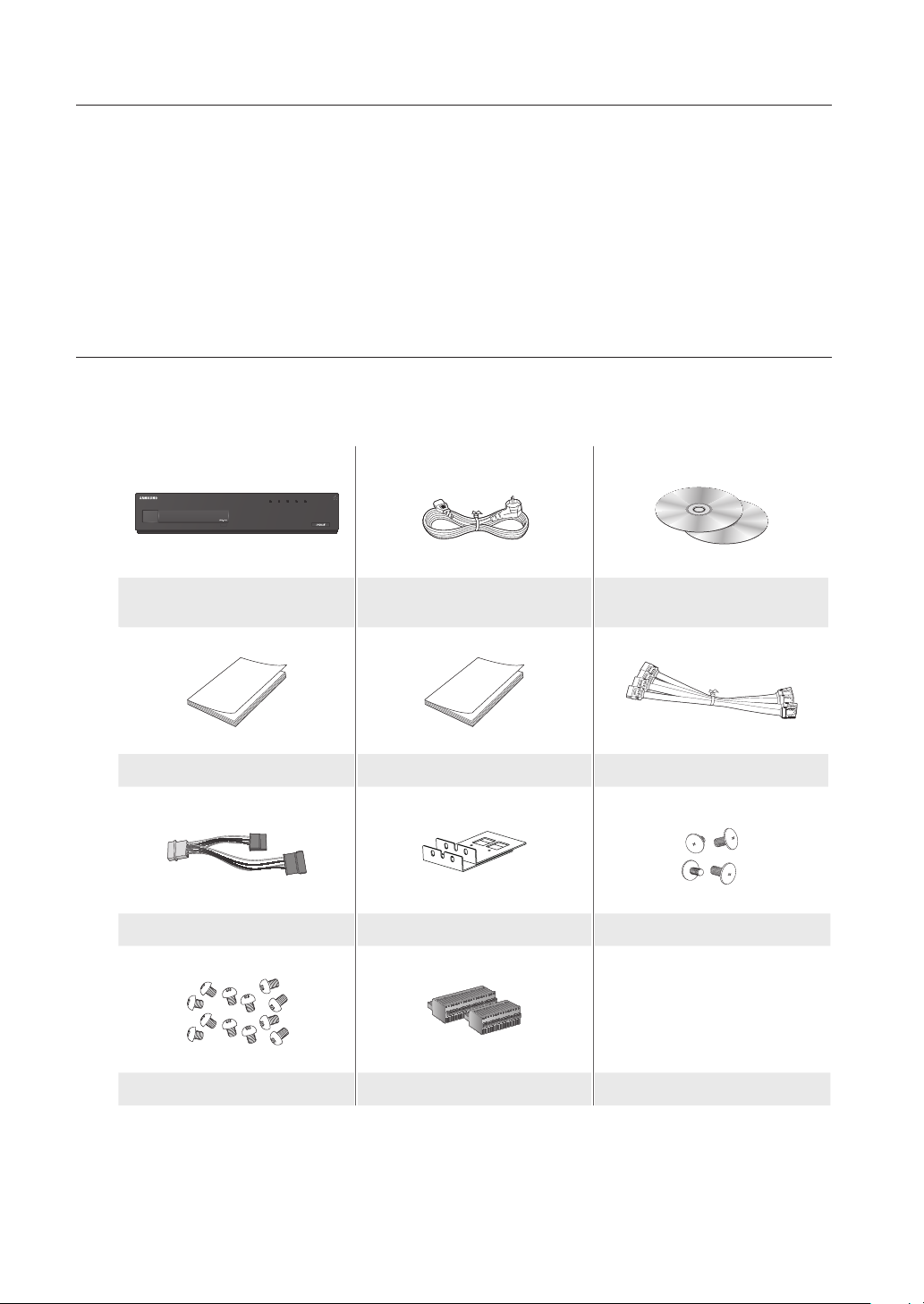
PACKAGE CONTENTS
Please unwrap the product, and place the product on a flat place or in the place to be installed.
Please check the following contents are included in addition to the main unit.
REC HDD ALARM NETWORK POWER
NVR Power Cable
User Manual Quick Guide (optional) SATA Cable
Additional SATA power cable Bracket Rack Bracket Fixing Screw
HDD Fixing Screw Terminal Block
Network Viewer Software /
User Manual and Installation Software CD
2_ English
` For a model with no built-in HDD, one SATA cable and 3 screws for fixing the HDD will be added by default.
M
Page 3
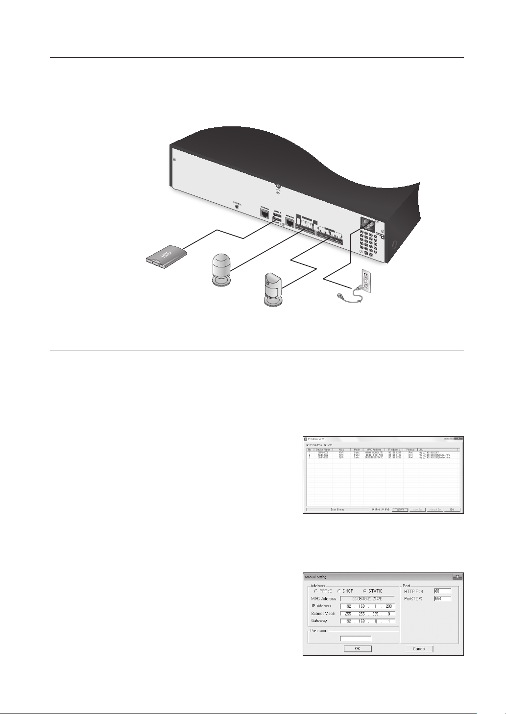
CONNECTING TO AN EXTERNAL DEVICE
NOT
USE
ALARM
RESET
ALARM OUT
NO NO
COMCOM
1 2 3 4
1 2 3 4 5 6 7 8 9
1011 1213 14 1516
COMCOM
NC NONO
G
ALARM IN
G
G
G
G
` Unrated or improper power source may cause damage to the system. Ensure that you use only the rated power source
J
before pressing the POWER button.
eSATA HDD
Alarm
Sensors
Power
NETWORKING WITH IP INSTALLER
Use provided IP Installer application program to search devices on the network and manually change the network
settings of the searched device.
Manual Network Setup
Run <IP Installer_vX.XX.exe> to display the device search list.
At the initial startup, both [Auto Set] and [Manual Set] will be grayed out.
1. Select a NVR in the search list.
Both the [Auto Set] and [Manual Set] buttons will be
activated.
2. Click [Manual Set].
The Manual Setting dialog appears.
The default values of <IP Address>, <Subnet Mask>,
<Gateway>, <HTTP Port> and <Port(TCP)> of the NVR
will be displayed.
` If found multiple devices assigned with the same IP address, assign different IP addresses to such devices to avoid conflict.
J
` If conflict has been occurred by sharing the same IP address by multiple devices, recovering may take some time.
3. In the <Address> pane, provide the necessary information.
• MAC (Ethernet) Address : The MAC (Ethernet) address of
the applicable NVR will be set automatically so you don't
need to input it manually.
` You can configure the static IP settings only if the DHCP checkbox
M
is unchecked.
English _3
Page 4

Auto Network Setup
Run <IP Installer_vX.XX.exe> to display the device search list.
At the initial startup, both [Auto Set] and [Manual Set] will be grayed out.
1. Select a NVR in the search list.
Both the [Auto Set] and [Manual Set] buttons will be activated.
2. Click [Auto Set].
The Auto Setting dialog appears.
The <IP Address>, <Subnet Mask>, and <Gateway> will be set automatically.
3. Enter the password.
This is the login password for the “admin” user who
accesses the NVR. The default password is “4321”.
` The default password can be exposed to a hacking thread so it is
M
recommended to change the password after installing the product.
` Note that the security and other related issues caused by the
unchanged password shall be responsible for the user.
4. Click [OK].
Auto network setup will be completed.
CONNECTING WEB VIEWER
1. Open your web browser and type the IP address or URL of
NVR into the URL address box.
` “192.168.1.200” is set to IP by default.
M
` Set to an available IP address in IP Installer or "Network >
Connection Mode”.
` The URL connection will be enabled only when the DDNS connection settings have been completed.
2. A user with the admin permissions should provide the admin
ID and password. A registered user should provide the user
ID and password.
` The default password can be exposed to a hacking thread so it is
J
recommended to change the password after installing the product.
` Set password for your wireless network if you use the product with a wireless router. Being not protected with password or
using the default wireless router password may expose your video data to potential threat.
` Note that the security and other related issues caused by the unchanged password shall be responsible for the user.
` It allow s up to 10 simultaneous access including the Admin and general users.
M
` It does not allow multiple login of the Admin user.
` The default ID of the admin account is “admin”, and the default password is “4321”.
` Password of the Admin and general users can be changed in <Permission Management> menu of the NVR.
` All settings are applied by the NVR’s settings.
4_ English
Page 5

3. Click <Install ActiveX Control...>.
4. When the installation confirm message appear, click [Yes ]
button.
5. When a program installation wizard window appears, press
the [Install] button to install the program.
6. When a login window appears after installing the program,
log in again.
Live Viewer's main screen appears when you log in
successfully after installing the program.
English _5
Page 6

REGISTERING THE CAMERA
You should register your camera and save corresponding settings before watching the video of registered camera in
Live Viewer.
To register the camera
1. Click the <Setup> menu.
2. Click the <Device>-<Camera>-<Registration> menu.
3. Click the <Auto> in Device Registration window.
“Add Camera Automatically” window appears to list up the
available cameras which are present in network.
4. Click the camera(s) to register in the list.
5. Enter relevant <ID> and <Password> for the selected
camera(s).
6. Click the [Register] button.
` When registering multiple cameras selected in a batch, only cameras
set with the same user ID and password from the selected will be
registered.
7. When “Connection Test” confirmation window appears,
check the registration status and click [OK] button.
“Add Camera Automatically” window is closed and
registered camera(s) is(are) displayed in the list.
8. Click [OK] button to complete the registeration.
6_ English
Page 7

This equipment has been tested and found to comply with the limits for a Class A digital device, pursuant to part 15 of the FCC Rules.
These limits are designed to provide reasonable protection against harmful interference when the equipment is operated in a commercial
environment.
This equipment generates, uses, and can radiate radio frequency energy and, if not installed and used in accordance with the instruction
manual, may cause harmful interference to radio communications. Operation of this equipment in a residential area is likely to cause
harmful interference in which case the user will be required to correct the interference at his own expense.
Samsung Techwin cares for the environment at all product manufacturing stages, and is taking measures to provide
customers with more environmentally friendly products.
The Eco mark represents Samsung Techwin’s devotion to creating environmentally friendly products, and indicates
that the product satisfies the EU RoHS Directive.
Correct Disposal of This Product
(Applicable in the European Union and other European countries with separate collection systems)
This marking on the product, accessories or literature indicates that the product and its electronic accessories (e.g. charger, headset, USB
cable) should not be disposed of with other household waste at the end of their working life. To prevent possible harm to the environment
or human health from uncontrolled waste disposal, please separate these items from other types of waste and recycle them responsibly
to promote the sustainable reuse of material resources.
Household users should contact either the retailer where they purchased this product, or their local government office, for details of
where and how they can take these items for environmentally safe recycling.
Business users should contact their supplier and check the terms and conditions of the purchase contract. This product and its electronic
accessories should not be mixed with other commercial wastes for disposal.
(Waste Electrical & Electronic Equipment)
Correct disposal of batteries in this product
(Applicable in the European Union and other European countries with separate battery return systems.)
This marking on the battery, manual or packaging indicates that the batteries in this product should not be disposed of with other household waste at the end of their
working life. Where marked, the chemical symbols Hg, Cd or Pb indicate that the battery contains mercury, cadmium or lead above the reference levels in EC Directive
2006/66. If batteries are not properly disposed of, these substances can cause harm to human health or the environment.
To protect natural resources and to promote material reuse, please separate batteries from other types of waste and recycle them through your local, free battery
return system.
Page 8

SALES NETWORK
SAMSUNG TECHWIN CO., LTD.
Samsungtechwin R&D Center, 701, Sampyeong-dong, Bundang-gu, Seongnam-si, Gyeonggi-do, Korea, 463-400
TEL : +82-70-7147-8740~60 FAX : +82-31-8018-3745
SAMSUNG TECHWIN AMERICA Inc.
100 Challenger Rd. Suite 700 Ridgefield Park, NJ 07660
Toll Free : +1-877-213-1222 Direct : +1-201-325-6920
Fax : +1-201-373-0124
www.samsungcctvusa.com
www.samsungtechwin.com
www.samsungsecurity.com
www.samsungipolis.com
SAMSUNG TECHWIN EUROPE LTD.
Samsung House, 1000 Hillswood Drive, Hillswood Business Park
Chertsey, Surrey, UNITED KINGDOM KT16 OPS
TEL : +44-1932-45-5300 FAX : +44-1932-45-5325
 Loading...