

Samsung SR-L677EV, SR-L679EV, SR-L629EV, SR-L627EV Service Manual
REFRIGERATOR
Model : SR-L677EV
SR-L679EV
SR-L627EV
SR-L629EV
REFRIGERATOR CONTENTS
1. Precautions
2. Product Specifications
3. Electrical Part Specifications & Standard
4. Circuit Diagram
5. Functions & Operating Instruction
6. Circuit Descriptions
7. Trouble shooting
8. Exploed View
9. Disassembly & Assembly
10. PCB Circuit Diagram
11. PCB Parts List
12. Specifications of Main Components
SR-L677EV
SR-L679EV
SR-L627EV
SR-L629EV
GREEN
Warning : Please abide by the following
precautions in order to conduct
the maintenance procedures in a
safety fashion.
1-1.
Caution when you replacing compressor.
• Do not smoke. Remove all the possible ignition
sources and then replace compressor in wellaired places.
• Don’t use welding machines if R600a refrigerant
does not exposed.
• In the case of gas leakage, always open the
windows.
• When cutting the SUCTION, DISCHARGE pipe
of the compressor, always take caution of the
inner pressure of the remaining gas.
1-2. Take out the power plug
• Always take out the power plug from the outlet
when doing repairs.
1-3. Be careful of electric shocks
• When inspecting the circuit, don’t touch the
battery charger and be careful of electric
shocks.
1-4. Use proper components
• Always use the component labeled in the
service component chart when replacing
components for repairs.
1-5. Use proper tools
• Always use proper tools for repairs. If worn out
tools are used, it would cause defects in tuning
and electrical contact, leading to accidents.
1-6.
When doing repairs, inspect the POWER
CORD or whether there is fire in the lead wire
and make sure they are replaced.
1-7. Cutting of LEAD-WIRE
• For connecting the lead-wire that has been cut
off, use soldering or connector and always
disconnect the vinyl tapes.
1-8. Check for disconnection
• After completing the assembly, always measure
the disconnection resistance level, and turn on
the power after checking it is above 1MΩ.
1-9. Earth
• Check the status of earthing and repair the
incomplete ones.
1-10. Be careful of children
• There is always the possibility of danger when
doing repairs so make sure that children can’t
come nearby.
Cleaning : After completing repairs, clean
the surrounding area and the
refrigerator and tell the consumer
about the repairs being made.
This appliance contains a small amount of the
refrigerant isobutane(R600a), a natural gas with high
environmental compatibility but which is also
combustible. When transporting and installing
the appliance, care should be taken to ensure
that no parts of the refrigerating circuit are damaged.
Refrigerant squirting out of the pipes could ignite or
cause an eye injury. If damage occurs nevertheless,
avoid any flames or potential sources of ignition, and
air the room in which the appliance is standing for
several minutes.
• In order to avoid the creation of a flammable gas-air
mixture if a leak in the refrigerating circuit occurs, the size
of the room in which the appliance may be sited depends
upon the amount of refrigerant used. The room must be
1m
3
in size for every 8 g of refrigerant R600a inside the
appliance. The amount of refrigerant contained in your
particular appliance is shown on the identification plate
inside the appliance.
• Never start up an appliance showing any signs damage. If
in doubt, consult your dealer.
Refers to prohibition.
Refers to prohibition of dismantling.
Refers to prohibition of contact.
Refers to guidelines which have to
be followed.
Refers to detaching the power plug
from the outlet.
Refers to earth connection for
preventing electric shocks.
Warning
Refers to possibility of death
or serious injury of a person.
Caution
Refers to possibility of injury
of a person or damage to
property.
1. Precautions
2
3
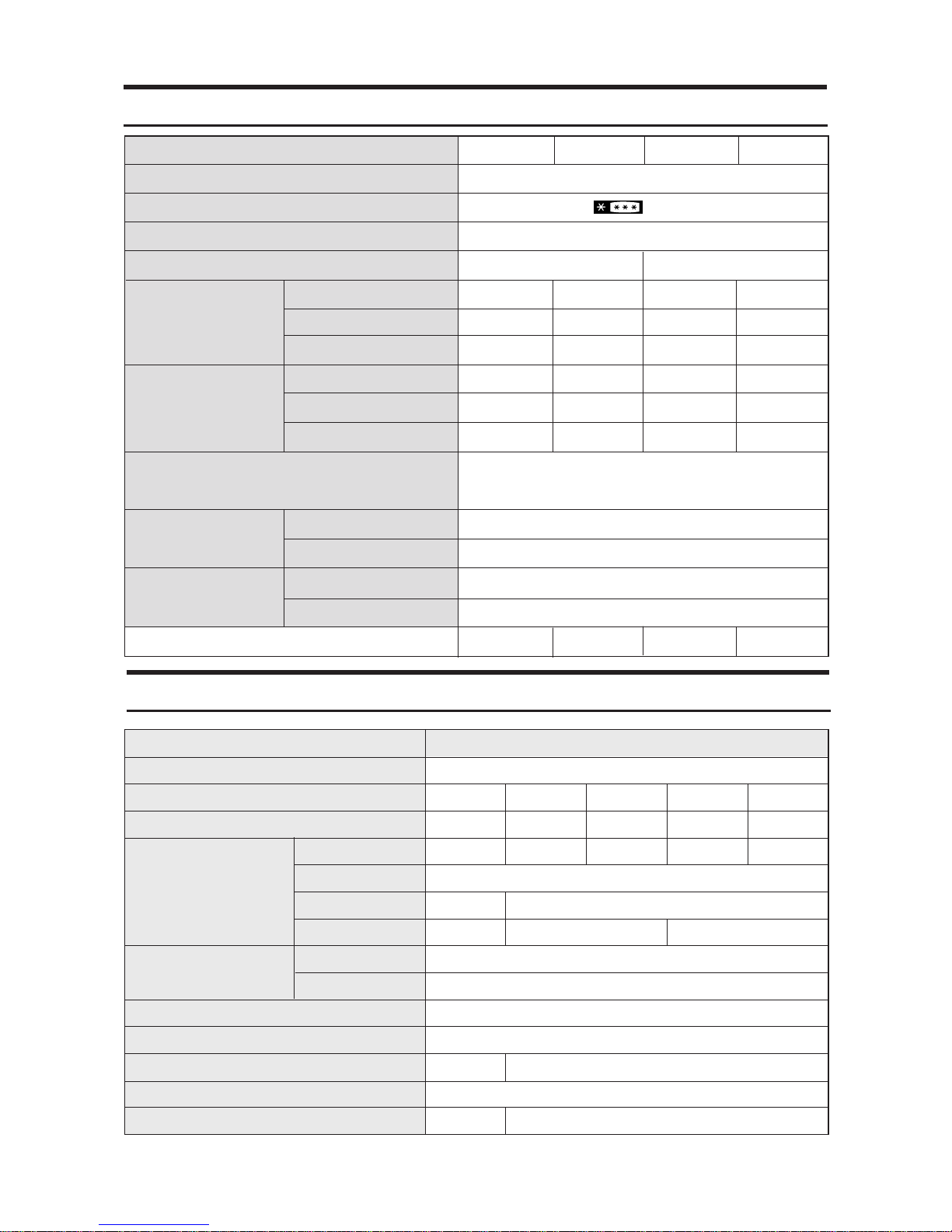
2. Product Specifications
3. Electrical part specifications & standard
SR-L629EV, SR-L679EV, SR-L627EV, SR-L677EV
230-240V
50HZ
MK4A3Q-L1U
R600a
2GSD(Mineral),
280cc
ID0.82XL3500,
5.10kg/
cm
2
DC12V
0.5A(S2PF101B)
230-240V
50HZ
DK182Q-L2U
220V
50-60HZ
SK190H-L2U
127V
60HZ
DK172P-L2U
(MK172P-L2U)
DK172C-L2U
(MK172C-L2U)
115V
60HZ
RSCR
R134a
Freol α-15c(Ester), 265cc
Freol α-15c(Ester), 265cc
(Freol α-10c(Ester), 265cc)
Split Fin & Tube Type
Split Fin & Tube Type
Forced & Natural Convection Type
Molecular Sieve XH-9
ID0.82
X
L3000 4.64kg/cm
2
BSBN(Brass screw)
AC250V 0.7A, AC125V 1.4A(SSD-6D)
Condenser
Dryer
Capillary tube
Earth screw
Door switch
Model
Starting type
Refrigerant
Oil Charge
Freezer
Refrigerator
Evaporator
Compressor
SR-L629EV SR-L679EV SR-L627EV SR-677EV
LMF 2 Door
(4-STAR)
Electronic control
CYCLO-PENTANE
CYCLO-PENTANE
A.B.S
A.B.S
103Kg 108Kg 102Kg 107Kg
Yes
820
X
720X1790 (mm) (SR-L629(7)EV)
820
X
770X1790 (mm) (SR-L679(7)EV)
No
Model
Type
Freezer performance
Temperature control
Water dispenser
Total
Freezer
Refrigerator
Total
Freezer
Refrigerator
Net Capacity
l
/(ft3)
Gross Capacity
l
/(ft3)
Cabinet insulation
Door insulation
Cabinet
Door
Liner
Foam
Net weight
Net dimension
(W
XDX
H)
501(17.69)
143(5.05)
358(12.64)
526(18.57)
168(5.93)
358(12.64)
551(19.46)
161(5.68)
390(13.77)
575(20.30)
185(6.53)
390(13.77)
506(17.87)
143(5.05)
363(12.82)
531(18.75)
168(5.93)
363(12.82)
556(19.63)
161(5.68)
395(13.95)
580(20.48)
185(6.53)
395(13.95)
STANDARD
ITEM
Model
Rated Voltage
Frequency
4
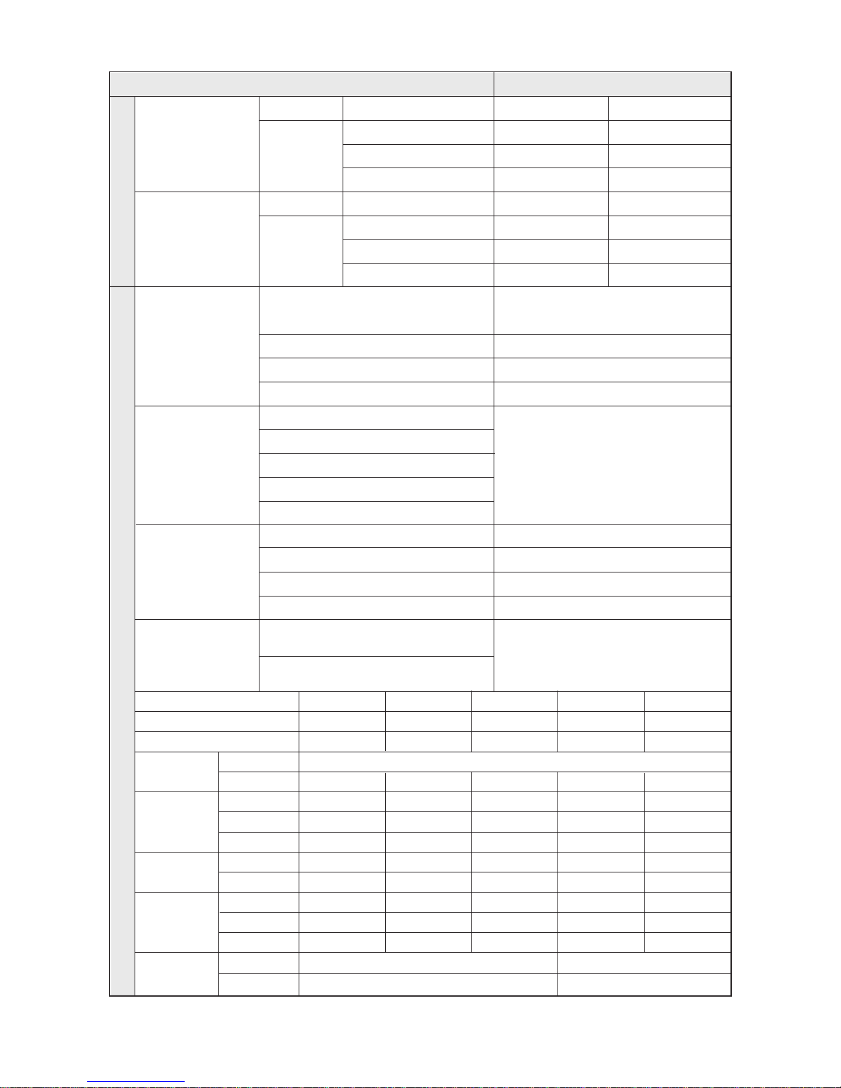
ITEM STANDARD
6 - 22hr(Vary according to the conditions used)
6 - 11hr(Vary according to the conditions used)
10 ±2min
4hr
±
10min
THERMISTOR (502AT), SPEC:5.0K
Ω
AT 25˚C
Freezer
Type
F-Sensor
Type
F-Sensor
ON(˚C)
–23.5˚C
–17.5˚C
–12.5˚C
ON(˚C)
2.5˚C
5.5˚C
8.5˚C
Temperature Selection
–25˚C
–19˚C
–14˚C
Temperature Selection
1˚C
4˚C
7˚C
OFF(˚C)
–26.5˚C
–20.5˚C
–15.5˚C
OFF(˚C)
–0.5˚C
2.5˚C
5.5˚C
Refrigerator
Defrosting
Sensor
Heater
Fuse
First Defrost Cycle
(Concurrent Defrost of F and R)
Defrost Cycle(FRE)
Defrost Cycle(REF)
Pause Time
Freezer-Sensor
Refrigerator-Sensor
FRE Evap-Sensor
REF Evap-Sensor
Ambient TEMP-Sensor
Defrost Heater(FRE)
Drain Heater(FRE)
Defrost Heater(REF)
Drain Heater(REF)
TemperatureElectrical parts
242W (115V, 127V, 220V, 240V)
52W(115V, 127V, 220V, 240V)
120W(115V, 127V, 220V, 240V)
38W(115V, 127V, 220V, 240V)
AC250V 10A 77±5˚C
Thermal-Fuse for preventing
overheating of Freezer Defrost-Heater
Thermal-Fuse for preventing
overheating of Freezer Defrost-Heater
230-240V 230-240V 220V 127V 115V
50Hz 50Hz 50-60Hz 60Hz 60Hz
MK4A3Q-L1U DK182Q-L2U SK190H-L2U
DK172P-L2U
(MK172P-L2U)
DK172C-L2U
(MK172C-L2U)
240V/15W
240V/25W
110V-130V/15W
110V-130/30W
Rated Voltage
Frequency
Compressor
Condenser
Over-Load
Protector
ST ARTING-
RELA Y
MOTOR-
FAN
LAMP
ST ARTING
RUNNING
MODEL
TEMP. ON
TEMP. OFF
MODEL
OPERA TION
FRE.
REF .
CIRCUIT
FRE.
REF .
350V AC, 3.5㎌
4TM232PHBYY -53
125±5
69±9
J531Q35E330M385-2
33±20%
IS3210-SNL5C
IS3208-SNL5B
IS3208-SCL5A
350V AC, 5.0㎌
4TM265RHBYY -53
130±5
69±9
J531Q35E330M385-2
33±20%
IS3210-SNL5C
IS3208-SNL5B
IS3208-SCL5A
350V AC, 8.0㎌
4TM314RHBYY -53
130±5
69±9
J531Q34E220M3502
22±20%
IS3210-SNF*B
IS3208-SNF7D
IS3208-SCF7A
250V AC, 12㎌
4TM435PHBYY -53
125±5
69±9
J531Q33E100M200-2
10±20%
IS3210-SNP6D
IS3208-SNP6H
IS3208-SC06A
250V AC, 12㎌
J531Q33E100M200-2
10±20%
IS3210-SNP6D
IS3208-SNP6H
IS3208-SCH6A
4TM437RHBYY-53
130±5
69±9
RSCR

5
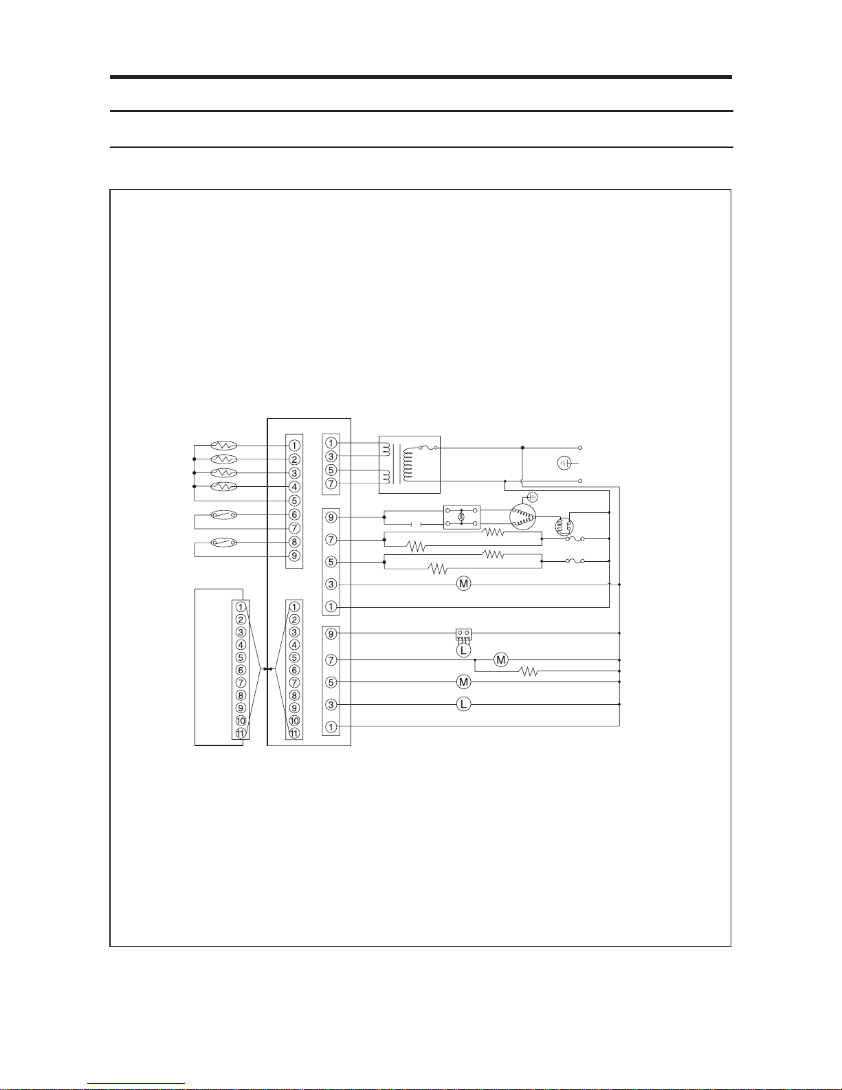
4. Circuit Diagram
4-1. 230V-240V/50Hz, 220v/50Hz,60Hz, 127V/60Hz, 115V/60Hz
6
F-ROOM SENSOR
BLU
YEL
ORG
PRP
GRY
BLK
BRN
WHT
S/BLU
CN30
CN10
CN70
CN71
BLK
BLK
BLK
BLK
DC TRANS
THERMAL FUSE
S/BLU
RUNNING CAPACITOR
COMPRESSOR
BRN
WHT
YEL
GRY
W/BLK
ORG
BLU
PNK
RED
E
N
A
GRY
PTC
F-THERMAL FUSE
R-THERMAL FUSE
BLU-BLUE
BRN-BROWN
E-EARTH
GRY-GRAY
ORG-ORANGE
PNK-PINK
PRP-PURPLE
RED-RED
S/BLU-SKY BLUE
WHT-WHITE
YEL-YELLOW
BLK-BLACK
W/BLK-WHITE/BLACK
DEFROST HEATER.F
DEFROST HEATER.R
F-DRAIN HEATER
R-DRAIN HEATER
COMP COOLING FAN
F-ROOM LAMP
R-ROOM FAN
R-LAMP HEATER
F-ROOM FAN
R/LAMP INVERTER
FLUORESCENT LAMP
M
C
S
2
3
2
O.L.P
1
5
36
CN50
BLK
BRN
REF
ORG
YEL
PNK
BLU
PRP
GRY
WHT
S/BLU
PANEL PCB
MAIN PCB
R-ROOM SENSOR
DEFROST SENSOR.F
DEFROST SENSOR.R
F-DOOR S/W
R-DOOR S/W
4-2.
230V-240V/50Hz, 60Hz, 220V/50Hz,60Hz, 127V/60Hz, 50Hz, 115V/50V,60Hz(INVERTER PCB)
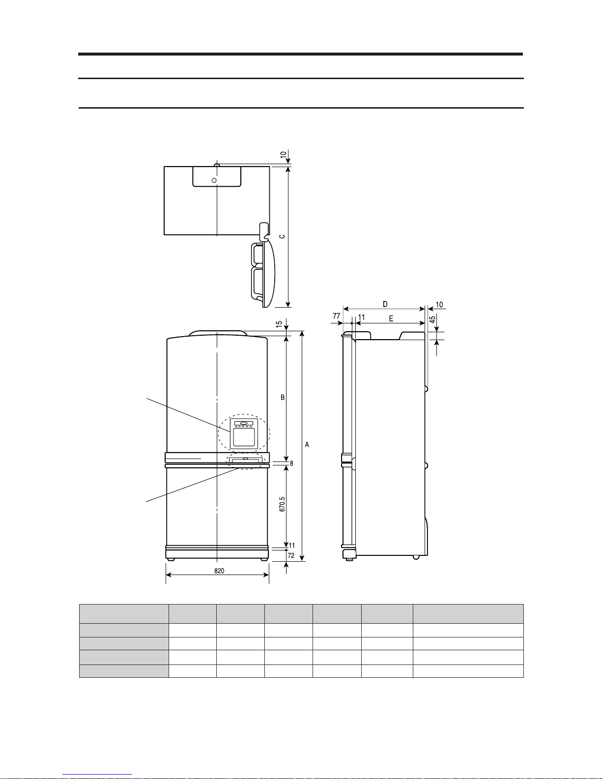
5-1. Product Dimension
5. Function & Operating Instruction
MODEL
SR-L679EV
SR-L677EV
SR-L629EV
SR-L627EV
A
1790
1790
1790
1790
B
1013.5
1013.5
1013.5
1013.5
C
1508
1508
1458
1458
D
755
755
705
705
E
667
667
617
617
Remarks
"X"
"Y"
"X"
"Y"
"X"
"Y"
7
8
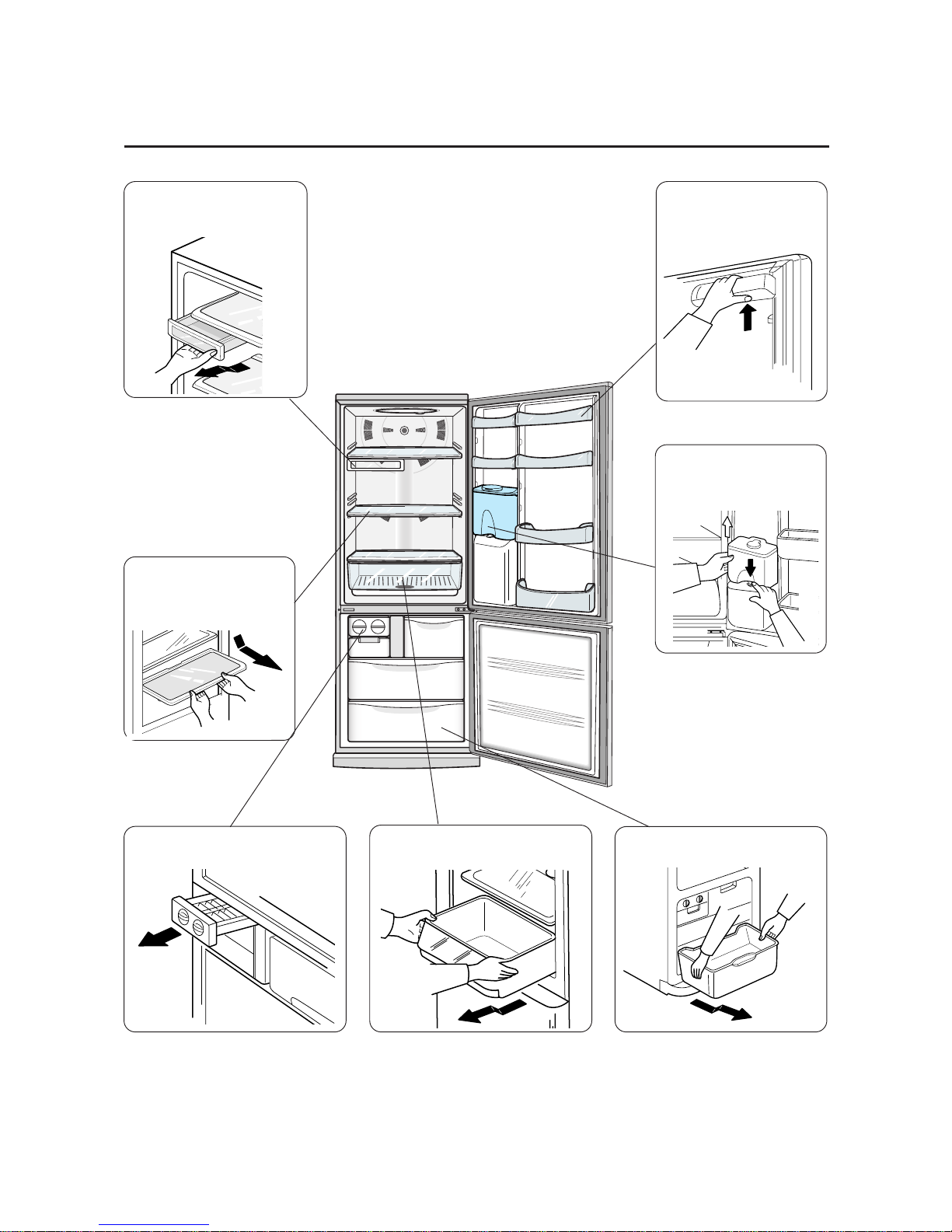
5-2. Part Name & Disassembly
• Top tray disassembly
Pull it forward.
Take out food stuffs and
pull it out by following the
arrow.
Take out the water bottle
with the bottom lever
pressed.
• Tray disassembly
Pull it out by following
the arrow.
• Ice compartment • Vegetable compartment
• Freezing compartment
•
•
•
•
•
•
•
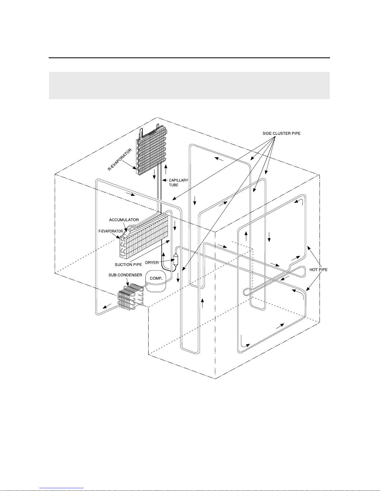
5-3. Circulation of Refrigerant (H.M CYCLE)
Compressor → Sub condenser → Cluster pipe → Hot pipe → Dryer → Capillary tube
→ R-Evaporator → F-Evaporator → Accumulator → Suction pipe → Compressor
9
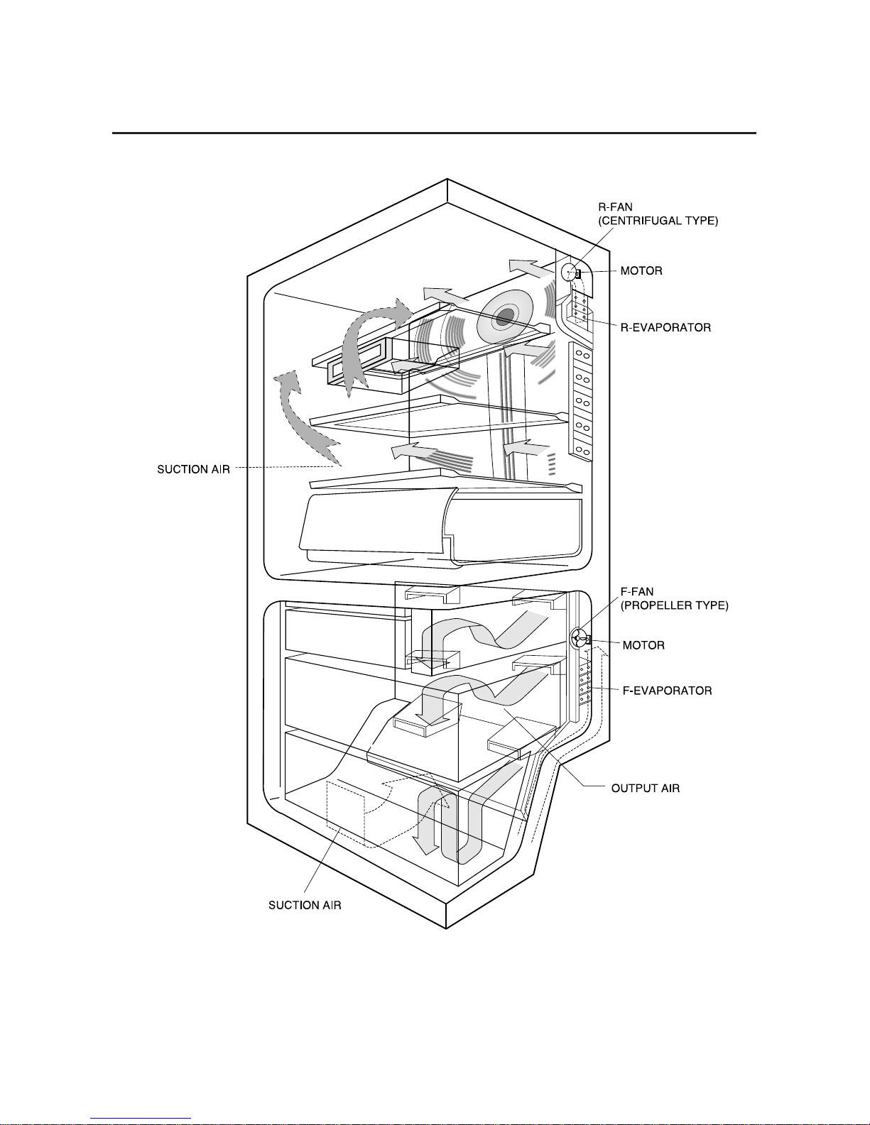
5-4. Cool Air Circulation
10
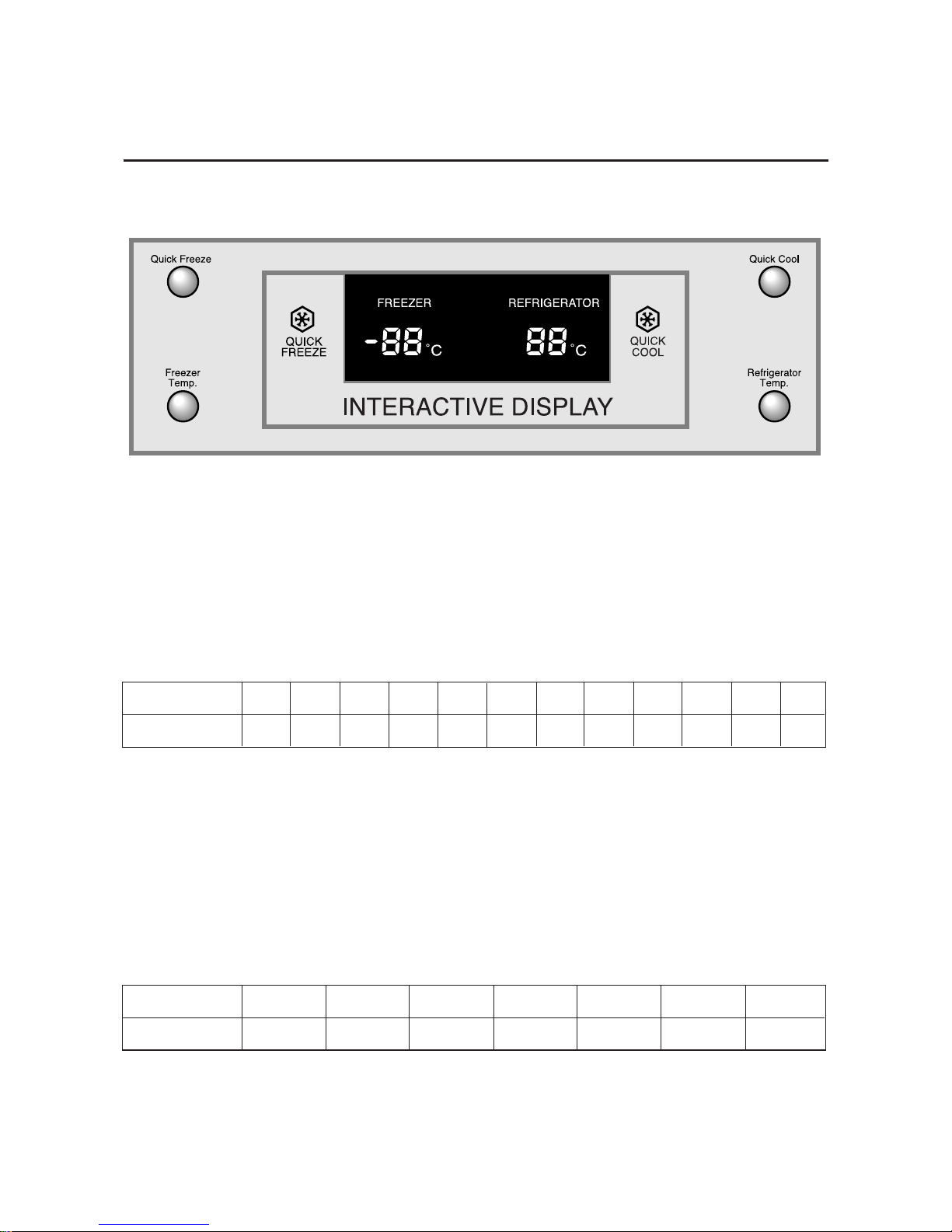
2. Temperature control function
1) Temperature selection of freezer compartment
❈ After the initial key selection, it displays the notch which is presently set up, then within 5
seconds re-memorize the key after 1-2) points mentioned below. If there is no input of the
key, it moves back to the previous temperature display.
1-1) From -14
˚C
~ -25˚C, each one key is selected in 1˚Cinterval.
1-2) Selection key operation for Freezer is set up orderly.
1-3) Actual temperature is indicated during both Power-On and electrical failure.
1-4) Standard temperature of each stage is as follows.(standard for 1/3 height)
1-5) After key input, seven-segment indication changes immediately but actual function
operates after 10seconds.
2) Temperature selection of refrigerator compartment
2-1) From 7
˚C
~ 1˚C, each one key is selected in 1˚Cinterval.
2-2) After the initial key selection, the former selected temperature is displayed, and within
5seconds temperature selection alters as in 2-3), and when final key input is done, the
final key input temperature converse into a set point after 10 seconds.
2-3) Set up is established orderly according to operation of selection button.
2-4) Actual temperature is indicated during both Power-On and electrical failure.
2-5) Standard temperature of each stage is as follows.(standard for 1/3 height)
2-6) After key input seven-segment indication changes immediately but actual function
operates after 10seconds.
Stage
Temperature
123456789101112
-14˚C -15˚C -16˚C -17˚C -18˚C -19˚C -20˚C -21˚C -22˚C -23˚C -24˚C -25˚C
Stage
Temperature
1234567
7˚C6˚C5˚C4˚C3˚C2˚C1˚C
1. Display design
5-5. Temperature Control and Other Capacity Explanation
11
3) Quick freeze
3-1) Press the on/off buttons of Quick Freeze so that the lamp of Quick Freeze is light up and
off and then it operates it’s function automatically.
3-2) It does not indicate from initial Power on.
a) When Quick Cool is selected, LED indication will immediately change but actual operation
operates after 10 seconds.
b) When Quick Cool is selected, COMP and R-Fan are operate until the temperature of
refrigerator compartment reached -2°C but the maximum operation time of Quick Cool is 2
hours and 30 minutes. So that, it switches off automatically after 2 hours and 30 minutes.
c) During the operation, the temperature of freezer compartment is controlled automatically
by the selected temperature.
d) Temperature display of refrigerator displays actual temperature.
❈ If you press Quick Freeze and Quick Cool button concurrently, each function operates
independently.
a) When Quick Freeze is selected, LED indication will immediately change but actual
operation operates after 10 seconds. (COMP and FAN operates continuously for 2 hours
and 30 minutes and it switches off automatically.)
b) When Quick Freeze is selected, it will operate unconditionally without considering the
temperature of freezer compartment.
c) During the operation, the temperature of refrigerator compartment is controlled
automatically by the selected temperature.
d) Temperature display of freezer displays actual temperature.
4) Quick cool.
4-1) Press the on/off buttons of Quick Cool so that the lamp of Quick Cool is light up and off
then it operates its function automatically.
4-2) It does not indicate from initial Power on.
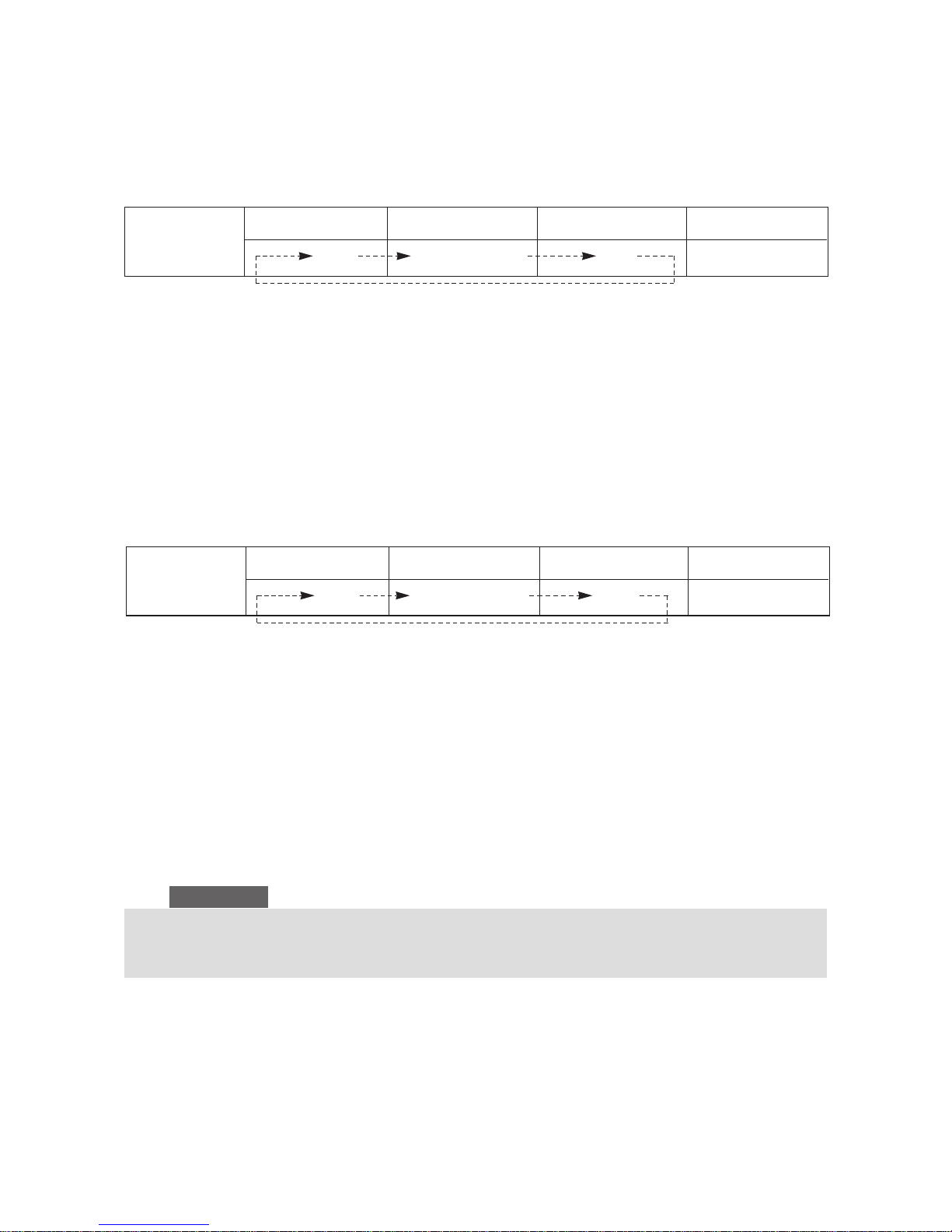
Change of
light indication
Initial Power On Pressed once time Pressed second time Remark
Off Quick Freeze On Off
Change of
light indication
Inition Power On Pressed Once time Pressed second time Remark
Off Quick Cool On Off
If you choose Quick Freeze or Quick Cool when freezer temperature is more than -10°C and
refrigerator temperature is above +10°C just as the initial Power On Condition, it operates
differently from what is mentioned above, and this is an exceptional case.
Reference
12

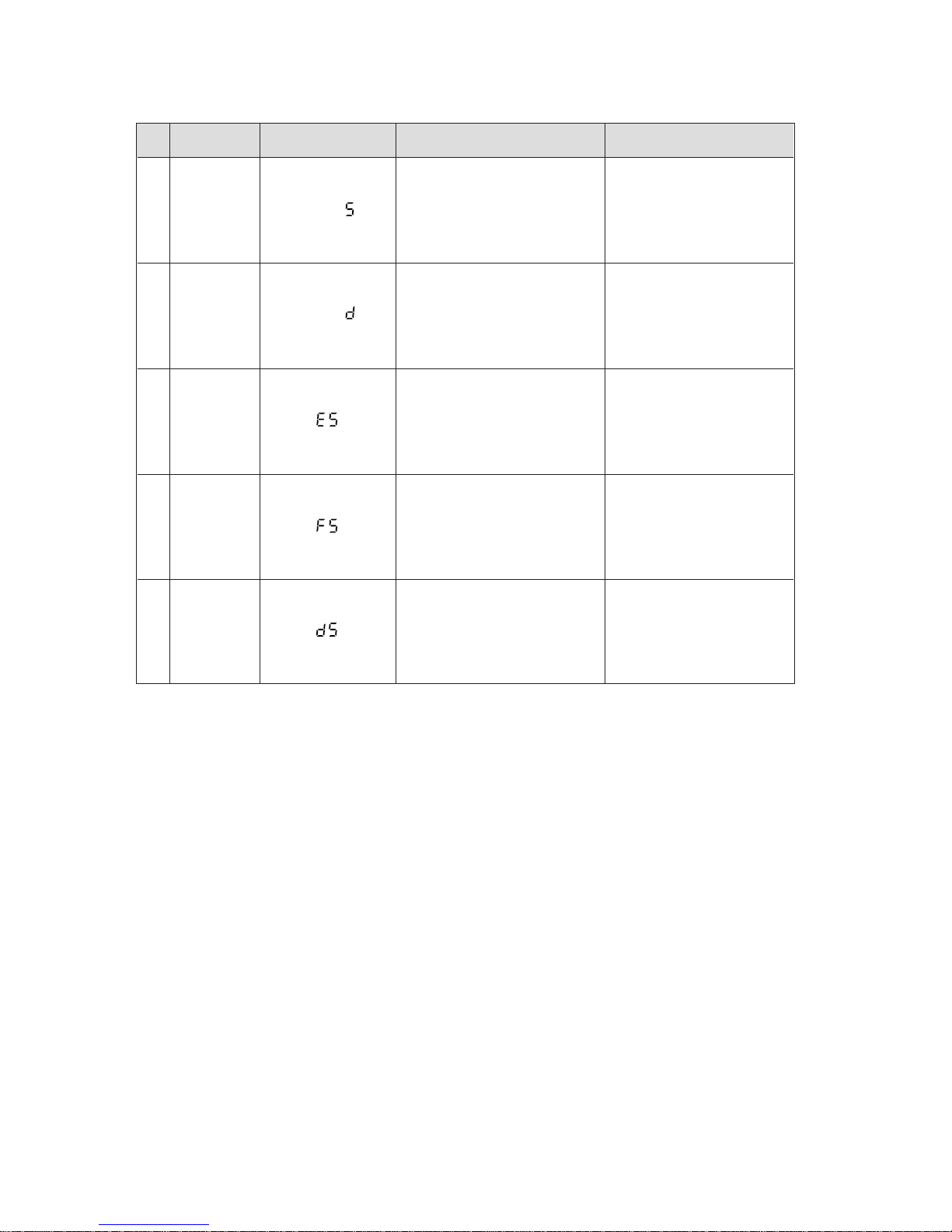
5) Sabbath function
5-1) It will turn to sabbath function if you press freezer and refrigerator temperatune button
together for 5 seconds.
5-2) When turned to sabbath function, all of the front display of LED turn off.
5-3) The light will not switch on even when the door is opened, and if it was switched on then
it will switch off.
5-4) To cancel the operation, you have to press freezer and refrigerator temperature button
together again for 5 seconds.
❈ This function is used only in special area.
3. Buzzer alarm function
1) Touch button type (ding-dong sound)
1-1) there is "ding-dong" sound to confirm input periodically for each one second for button
operation in each control panel.
1-2) key recognition is within 0.2 sec and "ding" sound beeps in continuous key recognition.
1-3) key recognition sound will first activate in other information.
2. Alarm when door is open
2-1)Alarm melody will run if door of freezer or refrigerator is open for 2 minutes or more.
2-2) If door continue to remain open alarm will run periodically.
2-3) Alarm will immediately stop when door is closed.
3. Forced running alarm and forced defrost alarm (beep sound).
3-1) If forced running, or defrost is chosen, there is a beep sound.
3-2) Once you press forced running test button, it will beep until you choose cancellation or it
cancel automatically (0.25sec ON/0.75sec OFF)
3-3) It will beep even during defrost is complete (include paused time) or until cancel button is
pressed.
3-4) During forced running alarm runs 0.1sec on and 1sec off, and during forced defrost alarm
runs as well 0.5sec on and 0.5sec off.
4. Defrost function
1) Once power is on and COMP is ON for 4 hours, both refrigerator and freezer starts to defrost
at the same time.
2) When the defrost time is reached, F-Fan and COMP runs pre-cooling for 20 minutes and
starts heating activity then the pause time is operated about 8 ~12 minutes(10±2minutes).
3) Actual defrost period is from minimum 6 hours up to maximum 11 hours, and freezer
compartment defrost period is from min. 12 hours up to max. 22 hours instantaneously
(COMP ON for additional period).
4) The decision of defrost period is maded by the ambient temperature and the count of door
open and the length of door open time.
5) Defrost periods memorize these information at MICOM as a case per hour. Therefore, case
of defrost period distinguishes per hour.
6) Influences of count and length of door open for time distinguisher get checked from the door
switchs of refrigerator compartment and freezer compartment.
7) If refrigerator compartment temperature is over trset-on+6
˚C
(at ambient temp. is over 21
˚C)
or trset-on+2˚C(at ambient temp is over 33
˚C),
COMP is runned by refrigerator
compartrment temperature. In this case, the defrost heater of refrigerator compartment starts
after 2 hours running of COMP.
8) After 7) is proceeded, the concurrent defrosting of freezer and refrigerator start after 4 hours
4 hours running of COMP.
9) If defrost operation is reached during quick freeze operation, quick freezer operation is
finished first and then defrost operation is proceeded.
13

5. Test function
❈ Test function is for the test of PCB, product, official inspection and ability of SVC.
❈ When s/w test is chosen and tested the product, you switch off and on again then let it run a
self-test.
1) Function of forced running.
1-1) If you choose PCB button once, COMP will automatically start.
1-2) When forced running is chosen, freezer will show “FF” and “1” in refrigerator automatically.
when this option is selected and 1 minute is past, temperature memorized will not change
even if you select defrost or cancel test activation (maintains F:-25˚Cand R:1
˚C
).
1-3) Forced running will activate only for 24 hours in full-down operation. Freezer and
refrigerator will automatically activate.
1-4) To cancel forced running power is off and on again or select test cancel mode.
1-5) During forced running alarm (0.25sec ON/ 0.75 sec OFF) runs until it is completed. The
alarm will continue without alarm key selection.
1-6) When forced running is selected, quick freeze operation does not activate.
2) Forced defrost function
2-1) When you press test button once more during forced running refrigerator compartment
activates defrost.(R-defrost only)
2-2) If you press button once more, freezer defrost will start at the same time with refrigerator.
2-3) If forced defrost function is selected, forced running will automatically cancel. And after
forced defrost is completed, it will proceed normal operation.
3) Test cancel mode
3-1) When you press test button once more during forced defrost in freezer and refrigerator, it
proceeds normal operation.
3-2) Alarm will stop during test cancel mode.
6. Function of initial Power ON
1) When power ON, refrigerator proceed initial self-test and, if normal, it indicate LED in all
operation panel for 2 seconds.
2) When proceeding self-test and if temperature sensor finds fault sensor, LED displays the
relatecl LED(see table 1.) for periods of 0.5 sec of related LED.
3) Switch on all LED for 2 sec. Initial display of freezer and refriger show actual temperature.
4) Keep condition of R-defrost heater and F-defrost heater for 3 sec for interval of 0.5 sec.
5) If F and R- defrost is finished at initial condition, COMP, F-fan and R-fan activates intervals
with 0.5 sec without inner temperature condition.
7. Power failure compensating function
1) function of notch save.
1-1) When you press quick freeze, quick cool, freezer, refrigerator button, micom save present
operating and display condition. Once the power is re-instated, the appliance will continue
to operate at the most recent temperature setting (except test mode.)
1-2) 1-1) Activity proceeds when F-evap. and R-evap. Temperature is below 10
˚C
added
together at initial power ON, it will activate, and if its more than 10˚Cit goes back to initial
mode activity. Quick freeze, quick cool and Sabbath function get not selected.
1-3) If power gets off during quick freeze, quick cool or sabbath function and then the power is
re-instated, the appliance will proceed quick freeze or quick cool function again at least
one of F-evap. or R-evap. temperature is below 10
˚C.
14

❈ Exhibition mode
1. When you press quick freeze button and freezer temp. button together the operation changes
into exhibition mode.
2. In exhibition mode, compressor is immediately off and defrost do not activate.
3. If you press quick freeze button and freezer temp. button together for 5 sec exhibition mode
cancel out and bact to nomal operation.
8. Self-test function
1) Define of the fault temperature sensor : temperature of the sensor is over between -50
˚C
(4.5volt) ~ +50
˚C
(0.5volt)
1-1) Self-test fuction due to power ON.
a) When a power is ON, it internal MICOM will decide faulty in temperature within 1 sec.
b) If faulty sensor is found, the “related display LED” switches on and off for 0.5 sec
intervals. And it will not beep (refer to self-test faulty indication table).
c) At the LED situation is the faulty sensor display, self-test function key ( press quick
freezer and quick cool button for 5 sec) is the control of normal temperature is delayed.
d) Fixing default sensor when there is an error, or press quick freeze and quick cool button
for 5 sec., it automatically cancel and activate normally.
2) Self-test function during normal activation
a) During normal activation, if you press quick freeze and quick cool key together for 3 sec.
temperature selection display of all ON/ OFF show for 2 sec by 0.5 intervals. Including
this 2 sec, press quick freeze and quick cool button together for 5 sec then it select selftest function.
b) If there is ding-dong sound it change into self-test function. If you press refrigerator temp.
selection button during 2 sec display toggle, it proceeds as the display function of the
presently operating parts.
c) If there is an error of the sensor, display of the faulty sensor continue for 30 sec then
activate normally (ding-dong alarm activates).
d) Button selecting is not selected during self-test proceeding.
15
1
2
3
4
5
No
• Open faulty
• Short faulty
• Open faulty
• Short faulty
• Open faulty
• Short faulty
• Open faulty
• Short faulty
• Open faulty
• Short faulty
Symptom
•
Suspected to be below -50
˚C
•
Suspected to be over +50
˚C
•Suspected to be below -50˚C
•Suspected to be over +50˚C
•
Suspected to be below -50
˚C
•
Suspected to be over +50
˚C
•
Suspected to be below -50
˚C
•
Suspected to be over +50
˚C
•
Suspected to be below -50
˚C
•
Suspected to be over +50
˚C
Remark
F-area
defroster
sensor
F-sensor
Outer sensor
R-area
defroster
sensor
R-sensor
Item
Freezer
Freezer
Freezer
Refrigerator
Refrigerator
Display LED
Table 1. Display table of self diagnosis.
9. Display function of the presently operating parts.
1) If you press quick freeze and quick cool button together for 3 sec during normal operation,
LED display refrigerator and freezer temperature will show ON/OFF for 2 sec at interval of
0.5 sec
16
2) At this moment if you take off quick freeze and quick cool button and press refrigerator temp.
button (ding-dong sound), it change into the display of the presently operating parts.
3) This display condition is unrelated to actual operation and it is an reference of indication that
MICOM commanded operating order).
10. Actual temperature and selected temperature in display function
1) Initial power ON
1-1) When initial power On is set, it reads both inner temperature of freezer and refrigerator.
Display range of freezer is -35
˚C
~+30˚Cand refrigerator -9˚C~+9˚C.
1-2) After this, if freezer inner temperature of a trset_off+1˚Cabove is recognized at least once,
LED display of freezer will change into a set-up temperature. And if refrigerator inner
temperature of trset_ off +3.5˚Cabove is recognized at least once, LED display of
refrigerator will change into a set-up temperatures. After all this, if freezer inner
temperature is above 0˚Cand refrigerator inner temperature above +15˚Cit will proceed
display blinking. But blinking operation only starts 10 minutes after it senses its problem
with inner temperature.
1-3) During the actual temp. dispaly condition, you choose quick freeze or quick cool function
the LED display will display actual temperature.
2) Stability in inner temperature
2-1) After selected temp. is reached, freezer and refrigerator display the selected temp.
a) If freezer inner temperature is above 0˚Cfor 10 minute, the display of the selected temp.
will blink.
b) If refrigerator inner temperature is above 15
˚C
for 10 minute, the display of the selected
temp. will blink.
c) When quick freeze is chosen, only freezer display will display actual temperature and the
actual temperature displays up to -35
˚C
.
1
2
3
4
5
6
7
8
9
10
11
12
No
Include R-fan activation
Defrost heater activation
Initial power is switched ON
Outer temperature is over 35
˚C
Outer temperature is below 20
˚C
Exhibition mode is operated together
Led ON when COMP activation is included
Led ON F-fan activation is included
Led ON when F-heater activation is included
Led ON when F-lamp activation is included
Led ON when R-lamp activation is included
Out temperature is about 21
˚C
~34
˚C
Operation Remark
R-fan
R-defrost heater
Initial start mode
Over load mode
Low temp.mode
Exhibition mode
Comp
F-fan
F-defrost heater
F-Lamp
R-Lamp
Normal mode
Ref. 6.button scan
and display circuitry
(see page 21)
Content
1 st letter “a” led in refrigerator
1 st letter “c” led in refrigerator
1 st letter “d” led in refrigerator
1 st letter “e” led in refrigerator
1 st letter “f” led in refrigerator
1 st letter “g” led in refrigerator
1 st letter “a” led in freezer
1 st letter “b” led in freezer
1 st letter “d” led in freezer
1 st letter “a” led in freezer
1 st letter “b” led in freezer
1 st letter “e”, ”f” led off in refrigerator
Display LED
17
Table 2. Display table of the presently operating parts.
3) Door open
when door is open, the related display shows an actual temperature.
3-1) Display range of freezer is -35˚C~ 30˚Cand refrigerator is -9˚C~9˚C.
3-2) If freezer inner temperature is above 0˚Cfor 10 minute, the display of the selected temp.
will blink.
3-3) If refrigerator inner temperature is above 15˚Cfor 10 minute, the display of the selected
temp. will blink.
3-4) When door is open, 1˚Cwill increase after delay time from the display before door
opens. When door close, 1˚Cwill decrease after delay time if there is a change in inner
temperature. Temperature will reach up to presently selected notch.
4) Defrost Display function
4-1) If defrost starts both freezer and refrigerator display the selected temperature. So it will
not blink for 2 hours even if it sensed faulty in inner temperature, after 2 hours it will
decide to blink or not.
❈ code for temperature might change due to after the progress in development in products
NO
1
2
3
4
5
6
7
8
9
10
11
12
13
DA41-00099A
DA41-00099B
DA41-00102A
DA26-30111H
DA26-30111F
DA26-30111C
DA32-00006C
DA32-00006C
DA32-10109H
DA32-10105A
DA41-00013B
DA41-20160A
DA41-20148A
PBA MAIN
PBA MAIN
PBAPANEL
DC TRANS
F, R DEF SENSOR
F, R DEF SENSOR
R SENSOR
F SENSOR
INVERTER PCB
W2 PJT
W2 PJT
W2 PJT
220~240V/50, 60Hz
105V/50,60Hz
127V/50,60Hz
PX-41C
PX-41C
PX-41C
PX-41C
220~240V/50,60Hz
127V/50,60Hz
105~115V/50,60Hz
1
1
1
1
1
1
1
1
1
1
1
1
1
Different
according to the
source of power
AHAM OPTION
Different
according to the
source of power
SPEC Q’ty RemarkCODE NO ITEM
(PCB Part List)
State of COMP cooling fan according to the ambient temperature (When COMP. is re-started)
- always OFF COMP cooling fan when ambient temperature is below 5˚C.
- COMP cooling fan always switch ON after 9 minute when ambient temperature is 6
˚C
~10˚C.
- COMP cooling fan always switch ON after 6 minute when ambient temperature is 11
˚C
~15˚C.
- COMP cooling fan always switch ON after 3 minute when ambient temperature is 16˚C~21˚C.
- COMP cooling fan always switch ON when ambient temperature is over 21˚C.
Reference
18
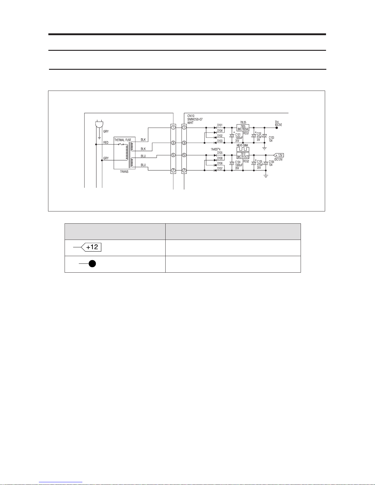
6-1. Power circuit
6. Circuit Descriptions
Voltage
(DC 12V)
Vcc (DC 5V)
Circuit used
Relay Operation & LED Display
Power around MICOM & Sensor Detector
1) The input AC voltage of DC-trans secondary registers 8V at CN10 between ①~③. The rectified
voltage passed through D101 ~ 104 becomes DC 5V through voltage regulator MC7805(REG1).
The power(DC5V) is supplied to the power around micom and sensor detector.
2) The input AC Voltage of DC-trans secondary registers 15V at CN10 between ⑤~⑦. The rectified
voltage passed throush D105 ~ D108 becomes DC 12V through voltage regulator MC7812CT
(REG2). The power (DC12V) is supplied to the relay operation and LED display.
19
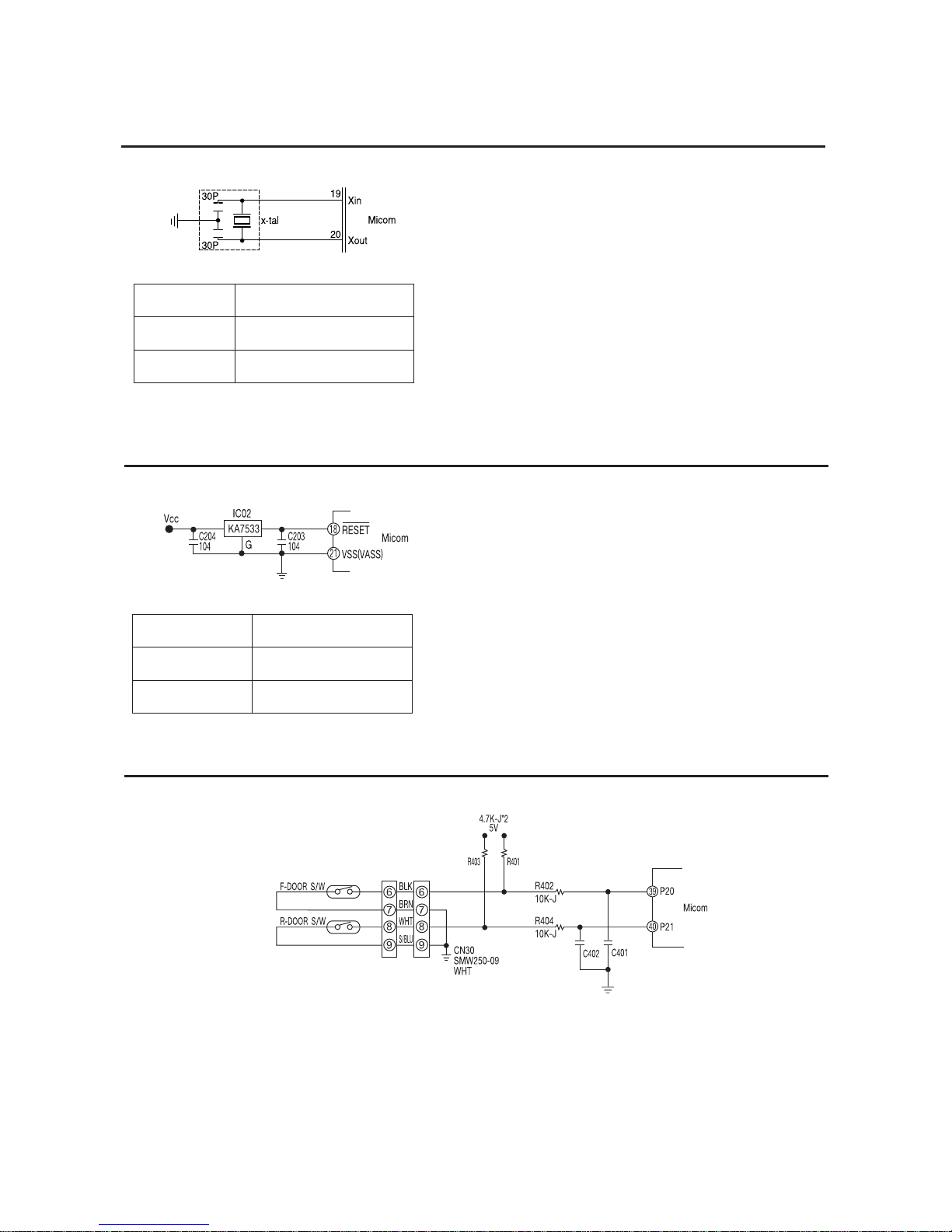
It is designed for clock generation and time
calculation for synchronizing transmission and
reception on the logic elements inside the MICOM.
If the X-TAL specification changes, MICOM may
make an error.
(The standard components should be used.)
Port
Xin(#19)
Xout(#20)
Oscillating Frequency
4.00MHz
4.00MHz
±0.5% Error
When power is supplied to MICOM, reset circuit
initializes RAM and other parts on MICOM to
initialize all programs. Reset voltage maintains “low”
for hundreds of µsec comparing to MICOM Vcc
voltage when power is input. It also maintains
“high”(5V) during normal operation. But, when Vcc
drops to 3.4V-3.7V, reset port becomes “low”.
Port
Vcc
Reset
Voltage
5V
5V
6-2. Oscillator
6-3. Reset Circuit
6-4. Door S/W Detector
20
1) If door is open, door S/W contact is closed. Then MICOM receives “low” signal and detects
door open then, Relay control circuit receives “HIGH” signal and turn Lamp on.
2) If door is closed, door S/W contact is open. Then MICOM receives “high” signal and detects
door close then, Relay control circuit receives “LOW” signal and turn Lamp off.
DOOR
F
R
Door Conditions
CLOSE
OPEN
CLOSE
OPEN
Door S/W Contact
OPEN
CLOSE
OPEN
CLOSE
MICOM
PIN NO
# 39
# 40
Micom Input Voltage
“HIGH”
“LOW”
“HIGH”
“LOW”
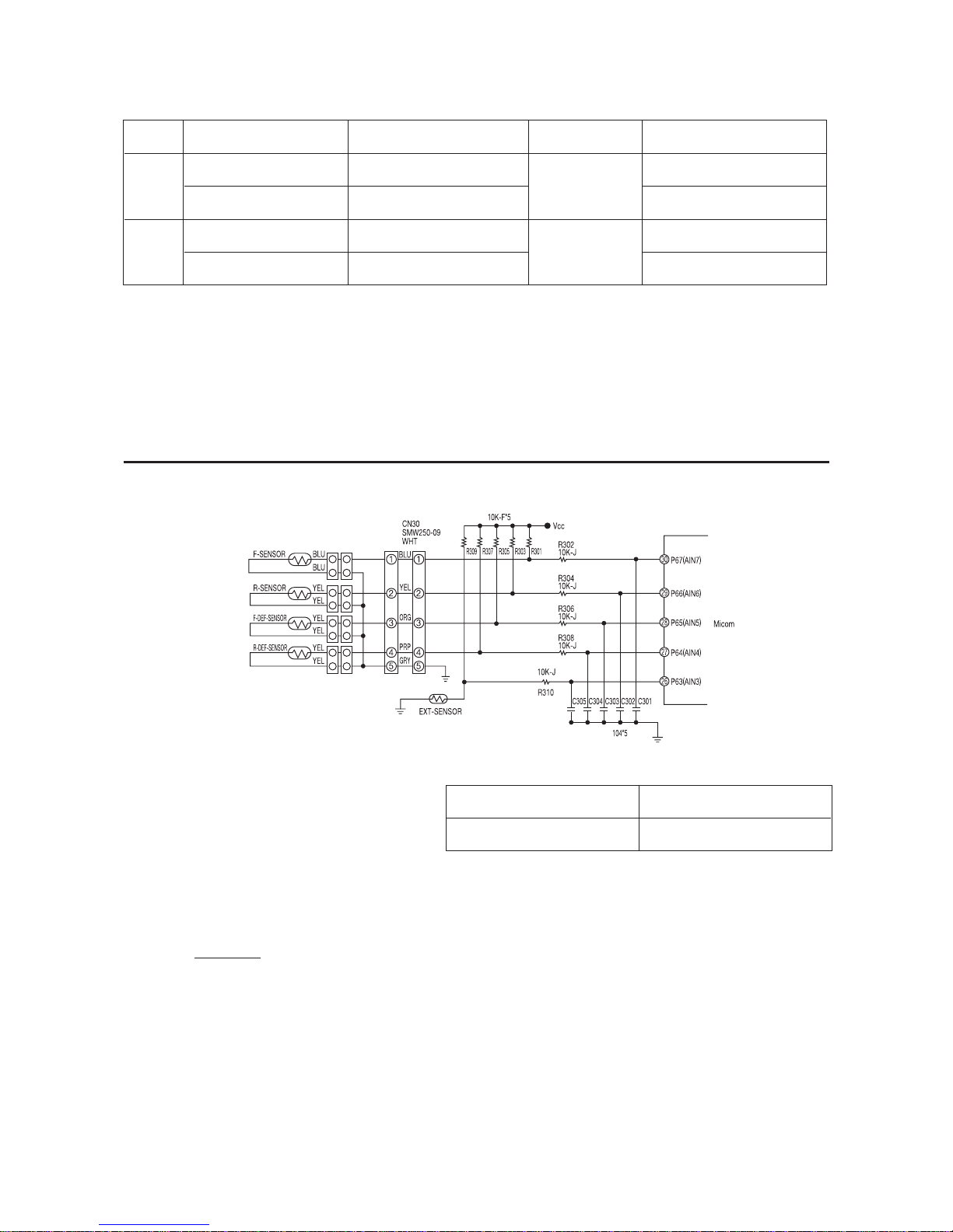
6-5. Temperature Sensor
1) The sensor uses the characteristics of thermistor. If temperature goes higher, resistance goes
lower. On the contrary, if temperature goes lower, resistance goes higher .
2) MICOM input voltage is counted by sensor as follows.
(V
CC : 5V, RTH : Sensor reisitance)
3) For the resistance information on temperature and MICOM input voltage, please refer the
conversion table. (Page. 41)
RTH
VF = X Vcc
RTH + R301
When Sensor is open
MICOM input “HIGH”
When sensor is cut off
MICOM input “LOW”
( Air Sensor)
21
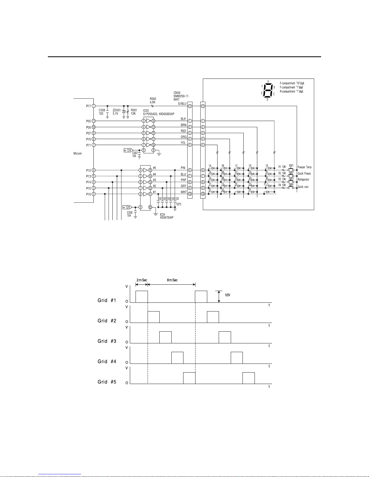
At that time, the peak to peak voltage of square signal registers around 12V. The grid #1 ~#5
waveforms are as follows.
6-6. Button scan and display circuitry
22
If MICOM outputs “high” signal to driver-IC(KID65003AP/S1P2655AØ3) according to each load
operation conditions, IC turns on and DC 12V flows to ground through the relevant relay coil. Then,
core is magnetized by the coil current, and relay contact switches on. When relay contact is on, AC
POWER is supplied to the relevant operation load, then which will be activated. If MICOM outputs
“low” signal, load operation stops with the relevant relay contact off.
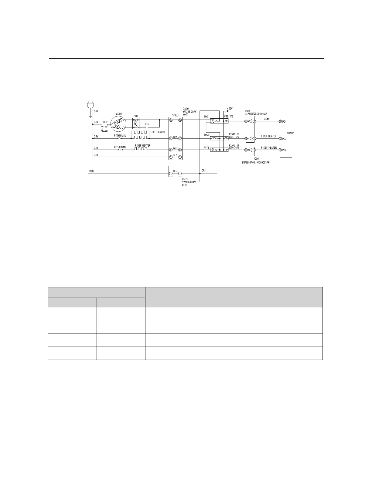
6-7. Load Operation
Like the above block diagram, operation of F, R defrost heater is detervminedy according to the
operation of relay for COMP. When comp relay is connected to NO terminal, comp operates.
However, in case of F, R defrost heater, electricity dose not pass through the heater though relay
works, But, if Comp relay is connected to NC terminal, comp does not operate and heater gets
electrieity according to operation of F, R defrost relay.
RELAY
Load
Comp Operation
Comp off, Defrost-Heater Off
Defrost-Heater On
Comp Off, Defrost-Heater Off
Remark
Defrost-Heater Power Off
Comp Power Off
COMP
on
on
off
off
Defrost Heater
off
on
on
off
23

6-8. Other option functions
6-9. Option Table
1) Freezer Temperature Shift (Unit ˚C)
SHIFT
Reference
-0.5
-1.0
-2.0
-3.0
+1.0
+2.0
+3.0
D601
-
-
-
-
•
•
•
•
D602
-
-
•
•
-
-
•
•
D603
-
•
-
•
-
•
-
•
2) Refrigerator Temperature Shift (Unit ˚C)
SHIFT
Reference
-0.5
-1.0
-2.0
-3.0
+1.0
+2.0
+3.0
D604
-
-
-
-
•
•
•
•
D605
-
-
•
•
-
-
•
•
D606
-
•
-
•
-
•
-
•
Temperature and function values are changeable by using main PCB switching diode.
• Note : If possible, do not change because the values have been set in factory. When changing option
functions, power should be turned off.
(Only initial power-on allows reading option function)
24
If possible, do not change because the values have been set in factory.
When changing option funcfions, power should be turned off.
NOTE
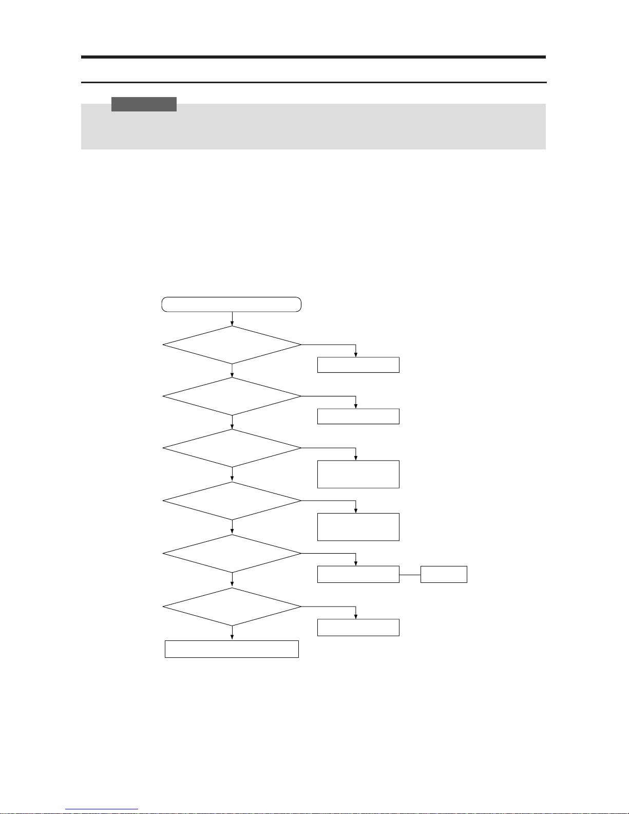
7. Trouble shooting
1) No power
1. Is the power cord well connected to wall outlet?
2. Refer to the reference
Precautions
Start
Y
N
Check wires
DC-Trans primary
power input?
Y
N
Replace DC-Trans
DC-Trans secondary
power input?
Y
N
Check REG102
(MC7812)
DC 12V output
from REG102?
Y
N
Check REG1
(KA7805)
DC 5V output
from REG1?
Y
N
Check wire connection Reference 1
(Page. 38)
Are wires connected to
panel securely?
Y
N
Replace panel PCB
Exchange main PCB
Panel PCB Ass’y
is OK?
25
 Loading...