

Samsung SRD470D500 User Manual

4 CHANNEL DVR
User Manual
SRD-470/470D

4 Channel DVR
User Manual
Copyright
©2011 Samsung Techwin Co., Ltd. All rights reserved.
Trademark
The name of this product is the registered trademark of Samsung Techwin Co., Ltd.
Other trademarks mentioned in this manual are the registered trademark of their respective company.
Restriction
Samsung Techwin Co., Ltd shall reserve the copyright of this document. Under no circumstances, this document
shall be reproduced, distributed or changed, partially or wholly, without formal authorization of Samsung
Techwin.
Disclaimer
Samsung Techwin makes the best to verify the integrity and correctness of the contents in this document, but
no formal guarantee shall be provided. Use of this document and the subsequent results shall be entirely on
the user’s own responsibility. Samsung Techwin reserves the right to change the contents of this document
without prior notice.
Warranty
If the product does not operate properly in normal conditions, please let us know. Samsung Techwin will resolve
the problem for free of charge. The warranty period is 3 years. However, the followings are excluded:
• Data loss due to a damaged hard disk
• If the system behaves abnormally because you run a program irrelevant to the system operation.
• Data loss due to virus infection
• Deteriorated performance or natural worn-out in process of time
• Sensory phenomenon that does not affect the performance or quality of the product (ex: working noise).
Design and specifications are subject to change without prior notice.
The default password can be exposed to a hacking thread so it is recommended to change the
password after installing the product.
Note that the security and other related issues caused by the unchanged password shall be
responsible for the user.
is the registered logo of Samsung Techwin Co., Ltd.

IMPORTANT SAFETY INSTRUCTIONS
Read these operating instructions carefully before using the unit.
Follow all the safety instructions listed below.
Keep these operating instructions handy for future reference.
1) Read these instructions.
2) Keep these instructions.
3) Heed all warnings.
4) Follow all instructions.
5) Do not use this apparatus near water.
6) Clean only with dry cloth.
7) Do not block any ventilation openings, Install in accordance with the manufacturer’s
instructions.
8) Do not install near any heat sources such as radiators, heat registers, stoves, or other
apparatus (including amplifiers) that produce heat.
9) Do not defeat the safety purpose of the polarized or grounding- type plug. A polarized plug has
two blades with one wider than the other. A grounding type plug has two blades and a third
grounding prong. The wide blade or the third prong are provided for your safety. if the provided
plug does not fit into your outlet, consult an electrician for replacement of the obsolete outlet.
10) Protect the power cord from being walked on or pinched particularly at plugs, convenience
receptacles, and the point where they exit from the apparatus.
11) Only use attachments/accessories specified by the manufacturer.
12) Use only with the cart, stand, tripod, bracket, or table specified by the
manufacturer, or sold with the apparatus. When a cart is used, use
caution when moving the cart/apparatus combination to avoid injury from
tip-over.
13) Unplug this apparatus during lightning storms or when unused for long
periods of time.
14) Refer all servicing to qualified service personnel. Servicing is required when the apparatus has
been damaged in any way, such as power-supply cord or plug is damaged, liquid has been
spilled or objects have fallen into the apparatus, the apparatus has been exposed to rain or
moisture, does not operate normally, or has been dropped.
English _3

overview
BEFORE START
This user manual provides Information for using the DVR such as brief introduction, part names, functions, connection
to other equipment, menu setup, etc.
You have to keep in mind the following notices :
• SAMSUNG retains the copyright on this manual.
• This manual cannot be copied without SAMSUNG’s prior written approval.
• We are not liable for any or all losses to the product incurred by your use of non-standard product or violation of
instructions mentioned in this manual.
• Prior to opening the case, please consult a qualified technician first. Whenever this is needed power must be
removed from the unit.
• Before installing an additional HDD or connecting an external storage device (USB memory or USB HDD) to this
DVR, check the compatibility. Consult your provider for the compatibility list.
Warning
❖ Battery
It is essential that when changing the battery in the unit, the replacement battery must be of the same type
otherwise there may be a possibility of an explosion.
The following are the specifications of the battery you are using now.
• Normal voltage : 3V
• Normal capacity : 170mAh
• Continuous standard load : 0.2mA
• Operating temperature : -20°C ~ +85°C
(-4°F ~ +185°F)
CALIFORNIA USA ONLY
This Perchlorate warning applies only to primary CR (Manganese Dioxide)
Lithium coin cells in the product sold or distributed ONLY in California USA.
“Perchlorate Material - special handling may apply,
See www.dtsc.ca.gov/hazardouswaste/perchlorate.”
Connect the power cord into a grounded outlet.
J
The Mains plug is used as a disconnect device and shall stay readily operable at any time.
Batteries shall not be exposed to excessive heat such as sunshine, fire or the like.
❖ System Shutdown
Turning off the power while the product is in operation, or undertaking improper actions may cause damage
or malfunction to the hard drive or the product.
Please turn off the power using the Power button on the front of your DVR.
After selecting <OK> in the pop-up menu, you can pull off the power cord.
You may want to install a UPS system for safe operation in order to prevent damage caused by an
unexpected power stoppage. (Any questions concerning UPS, consult your UPS retailer.)
❖ Operating Temperature
The guaranteed operating temperature range of this product is 0°C ~ 40°C (32°F ~ 104°F).
This product may not work properly if you run right after a long period of storage at a temperature below the
guaranteed one.
Prior to using a device that has been stored for a long period in low temperatures, allow the product to stand
at room temperature for a period.
Especially for the built-in HDD in the product, its guaranteed temperature range is 5°C ~ 55°C (41°F ~ 131°F).
Likewise, the hard drive may not work at a temperature below the guaranteed one.
❖ Ethernet Port
This equipment is in door use and all the communication wirings are limited to inside of the building.
4_ overview

CONTENTS
OVERVIEW
4
INSTALLATION
13
CONNECTING WITH
OTHER DEVICE
17
LIVE
21
4 Before Start
7 Features
9 Part Names and Functions (Rear)
10 Part Names and Functions (Front)
12 Remote Control
OVERVIEW
13 Checking the installation environment
14 HDD Addition
17 Connecting the Video, Audio, and Monitor
17 Connecting the USB
17 Connecting POS Device
18 Connecting the Alarm Input/Output
18 Connecting the RS485 Device
19 Connecting the Network
21 Getting Started
23 Live Screen Configuration
27 Live Mode
29 Spot Out
29 Zoom
30 Audio ON/OFF
30 Freeze
30 Event Monitoring
USING THE DVR
32
32 System Setup
42 Setting the Device
50 Setting the Recording
53 Setting the Event
56 Backup
57 Network Configuration
64 Controlling a PTZ device
English _5

overview
SEARCH & PLAY
66
WEB VIEWER
71
BACKUP VIEWER
94
APPENDIX
96
66 Search
69 Playback
71 Introducing Web Viewer
72 Connecting Web Viewer
73 Using Live Viewer
79 Using Search Viewer
83 Viewer Setup
93 About
93 Mobile Viewer
94 SEC Backup Viewer
96 Product Specification
99 Product Overview
100 Default Setting
103 Troubleshooting
6_ overview

FEATURES
The SRD DVR employs H.264 video encoding for 4 channel inputs and G.723 audio encoding for 4 channels while
simultaneously supports hard disc recording and playback.
These DVRs also supports network connectivity, providing remote monitoring from a remote PC transferring video
and audio data.
• 4 CH Composite Input Connectors
• CIF(S)/2CIF(M)/4CIF(L) Recording
• Network transfer regardless of the recording conditions using network specific codec
• Improved quality using de-interlace chip
• HDD information and status with HDD SMART
• Record at 4CIF Size 120(NTSC)/100(PAL)IPS
• 4 CH Loop Through video port
• HDD Overwrite
• Massive HDD backup via USB 2.0
• Backup using USB 2.0 memory and/or external CD/DVD writer
(DVD writer not supported in SRD-470)
• Record and play 4 CH video data simultaneously
• Various search modes (time, event, backup, POS, motion detection)
• Lots of storage modes (time lapse, event, timed recording)
• HDD extension (USB 2.0)
• Alarm connection
• Remote monitoring via Windows Network Viewer
OVERVIEW
English _7
overview
Standards Approvals
This equipment has been tested and found to comply with the limits for a Class A digital device, pursuant to part 15
M
of the FCC Rules. These limits are designed to provide reasonable protection against harmful interference when the
equipment is operated in a commercial environment.
This equipment generates, uses, and can radiate radio frequency energy and, if not installed and used in accordance
with the instruction manual, may cause harmful interference to radio communications. Operation of this equipment
in a residential area is likely to cause harmful interference in which case the user will be required to correct the
interference at his own expense.
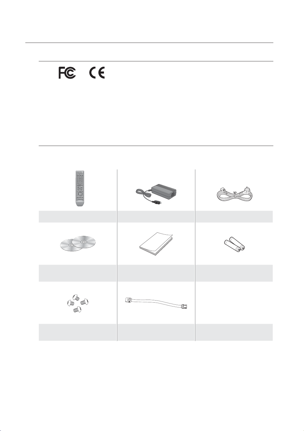
Package Contents
Please unwrap the product, and place the product on a flat place or in the place to be installed.
Please check the following contents are included in addition to the main unit.
Remote Control Adaptor Power Cable
Network Viewer Software /
User Manual CD
HDD Fixing Screw
(Only applicable for SRD-470 : 4EA)
For models that are not equipped with the HDD, one SATA cable is provided for HDD installation.
M
❖ Power Adaptor
• Input : AC100-240V~, 50/60Hz, 1.2A
• Output : DC12V - 4A
(Only applicable for SRD-470 : 1EA)
User Manual Remote Control Battery (AAA)
SATA Cable
8_ overview
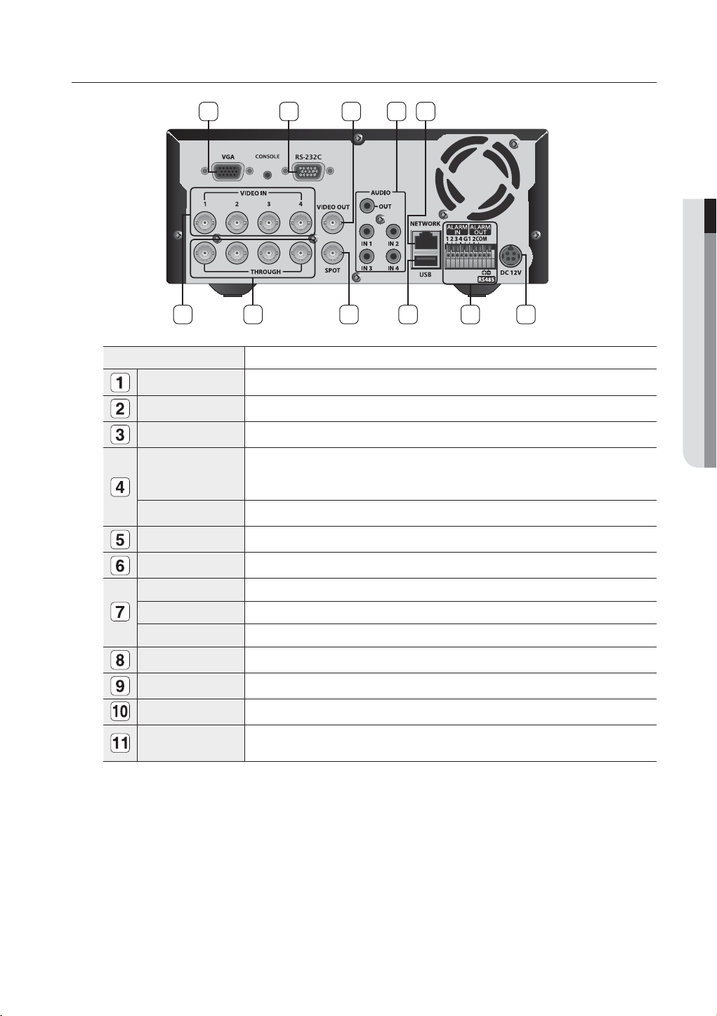
PART NAMES AND FUNCTIONS (REAR)
1
2
3 4 5
11
Part Names Functions
VGA Output port for VGA video signal.
RS-232C RS-232C communications port.
VIDEO OUT BNC type of output port for the composite video signal.
Output port (RCA jack) for the audio signal.
AUDIO OUT
AUDIO IN 1~4 Output ports (RCA jacks) for the audio signal.
It is recommended to use an amplifier-integrated speaker for the output of the audio
signal.
OVERVIEW
678910
NETWORK Network connection port.
DC 12V Port to be connected to the 12V power source.
ALARM IN 1~4, G : Alarm input ports.
ALARM OUT 1, 2, COM : Alarm output ports.
RS485 Used to establish RS485 communications. (TX+, TX-)
USB USB connection port.
SPOT BNC type of output port for the Spot signal.
THROUGH Port to transfer the video signal to other video devices.
VIDEO IN
Input port for the composite video signal.
Supports both NTSC and PAL video signal.
English _9
overview
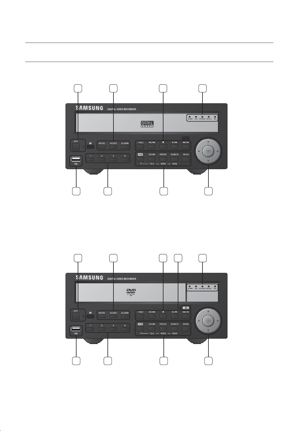
PART NAMES AND FUNCTIONS (FRONT)
SRD-470
SRD-470D
1 3 5
2
SRD-470
8 7 69
3 5
21
4
10_ overview
SRD-470D
9
8 7 6
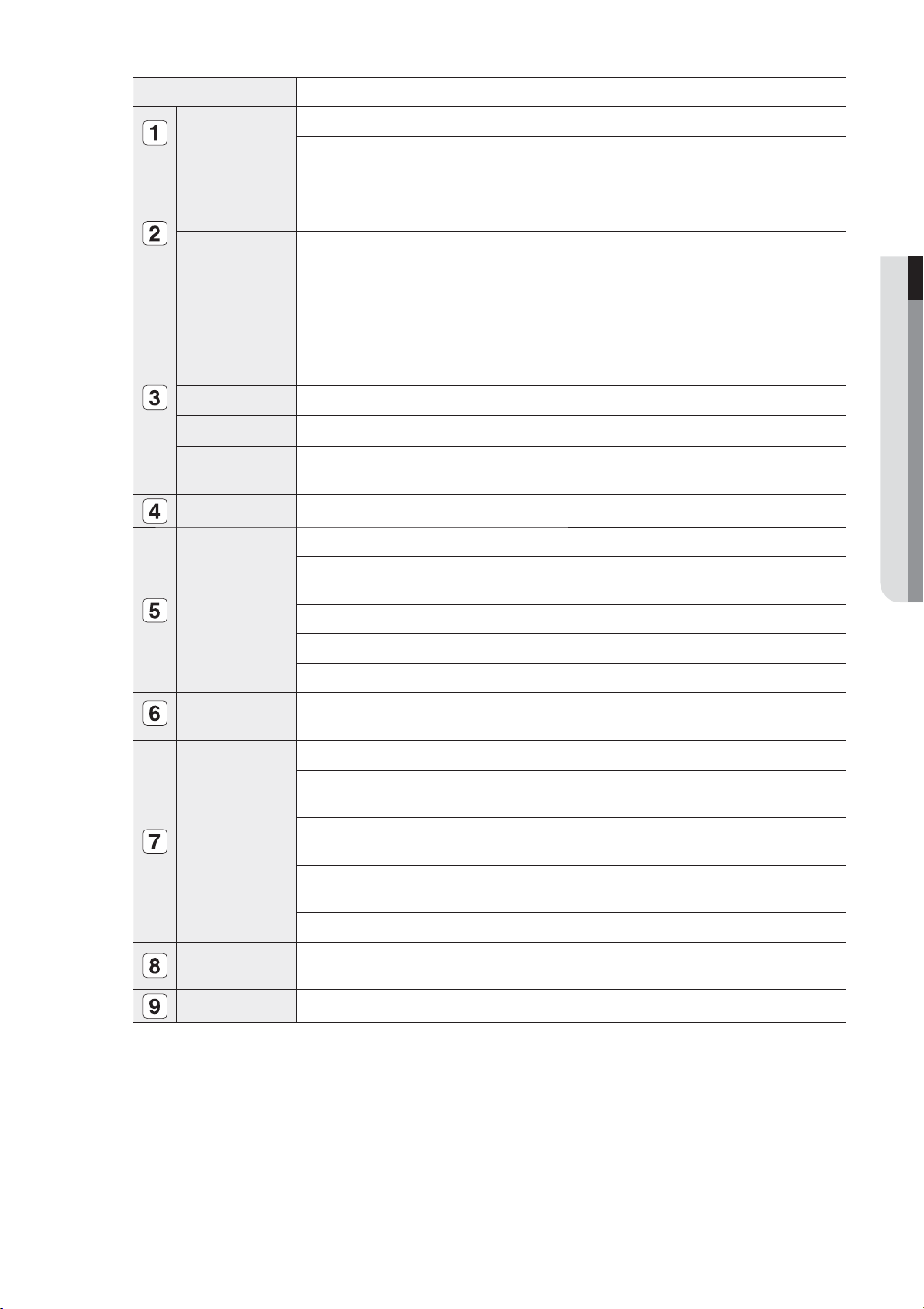
Part Names Functions
Power
MODE
AUDIO Sets Audio ON/OFF.
ALARM
REC Starts or ends the recording.
/
►/
/
Open/Close Used to open and close the DVR-RW disc tray. (available for SRD-470D only)
LED Indicator
Direction &
Select Button
Camera Control
Channel
Power LED : Displays the power ON/OFF status.
Power Button : Used to turn the DVR ON/OFF.
In Live mode, pressing it will switch the mode to 4-split, PIP, and Auto Sequence in sequence.
Each button press in Search mode will toggle the screen mode between 4-split and single screen.
For the Play Screen mode, refer to “Play”. (page 69)
Used to acknowledge the alarm which will clear alarm LED, sound and icon when alarm has
been generated.
Step Rewind ( ) : Used for backward frame-by-frame search while in PAUSE.
Fast Rewind () : Used for quick backward search while in Play.
Stop : Used to stop the playback.
Play/Pause : Used to pause or resume the screen.
Fast Forward () : Used for quick forward playback.
Step Forward ( ) : Used for forward frame-by-frame search while in PAUSE.
ALARM : Lights on when an event occurs.
HDD : Displays the normal access to HDD.
Upon access to HDD, LED is on.
NETWORK : Displays both network connection and data transfer status.
BACKUP : Displays when Backup is in progress.
REC : Lights on when recording is in progress.
Used to change a value or move the cursor up/down/left/right (◄ ►).
Selects a menu item or executes the selected menu.
PTZ : Sets PTZ Mode ON/OFF.
ZOOM(TELE) : Sets the screen to the x2 digital zoom.
Runs the TELE function in the PTZ Mode.
FREEZE(WIDE) : Runs the FREEZE function in the Live Mode.
Runs the WIDE function in the PTZ Mode.
SEARCH(VIEW) : This is the function that switches over to the Search mode.
(Perform the VIEW function when selecting the PTZ button.)
MENU : Used to access the Menu screen or move to the previous menu.
Used to select channel numbers directly in the Live Mode, or numbers in the numeric input
mode.
OVERVIEW
USB Port Connects the USB devices.
English _11
overview
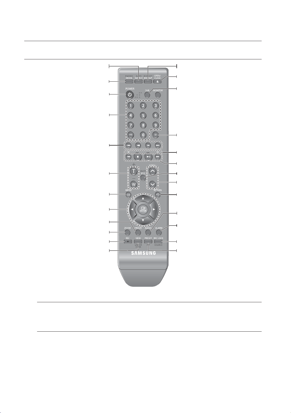
REMOTE CONTROL
Displays the search menu.
Changes the screen mode.
Displays the Exit pop up screen.
Used as the numeric input keys, or displays a single
Skip Backward (by unit time),
Slow Rewind, Slow Forward,
Skip Forward (by unit time)
Goes to the system menu screen.
Up/Down/Left/Right(▲▼◄ ►)/ENTER
Moves the cursor up/down/left/right, and runs the
Freezes the screen temporarily.
Runs the digital zoom (x2) function.
Starts or ends the live recording.
Runs the View function in the PTZ mode.
SEARCH
MODE
POWER
NUMBER [0~+10]
channel.
T/W
Zooms in or out.
MENU
Select Menu.
FREEZE
ZOOM
REC
VIEW
BACKUP
Displays the Backup Menu.
OPEN/CLOSE (available for SRD-470D only)
Opens or closes the CD tray.
DVR
Activates the DVR function.
ID
Sets the ID of the system.
Select 2 digits from 0 ~ 9 while pressing the ID Key.
Move Frame
While paused, moves to the previous/next frame.
FR, STOP, PLAY/PAUSE, FF
PTZ
Displays or ends PTZ.
SCROLL ,.
Moves the menu scroll.
RETURN
Returns to the previous screen.
AUDIO
Turns Audio on/off.
ALARM
Cancels the Alarm.
REC LOCK
Selects the recording lock function.
PRESET
Displays the Preset Setup.
Using the Numeric buttons
1. Press any button among 1 to 4.
2. Move to the selected channel number.
Changing the Remote Control ID
1. Press the ID button of the remote control and check the ID displayed on the DVR screen.
The factory default ID of the remote control is 00.
2. Enter 2 digits of your selection in order, while pressing the system [ID] button.
3. When ID input is done, press the system [ID] button again to check the setting.
If you want to change the remote control ID to 08: Press 0 and 8 in order while the system [ID] button is pressed.
M
Remote control's ID and DVR’s ID should be matched for proper operation. Refer to “Remote Devices”. (Page 46)
12_ overview
installation
2
3
4
MODE
AUDIO
ALARM
REC
ZOOM
REC
FREEZE
SEARCH
TELE
WIDE
VIEW
MENU
BACKUP
NETWORK
HDD
ALARM
DIGITAL VIDEO RECORDER
SRD-470D
Please take note of the followings before using this product.
• Do not use the product outdoor.
• Do not spill water or liquid in the connection part of the product.
• Do not impose the system to excessive shock or force.
• Do not pull out the power plug forcefully.
• Do not disassemble the product on your own.
• Do not exceed the rated input/output range.
• Use a certified power cord only.
• For the product with an input ground, use a grounded power plug.
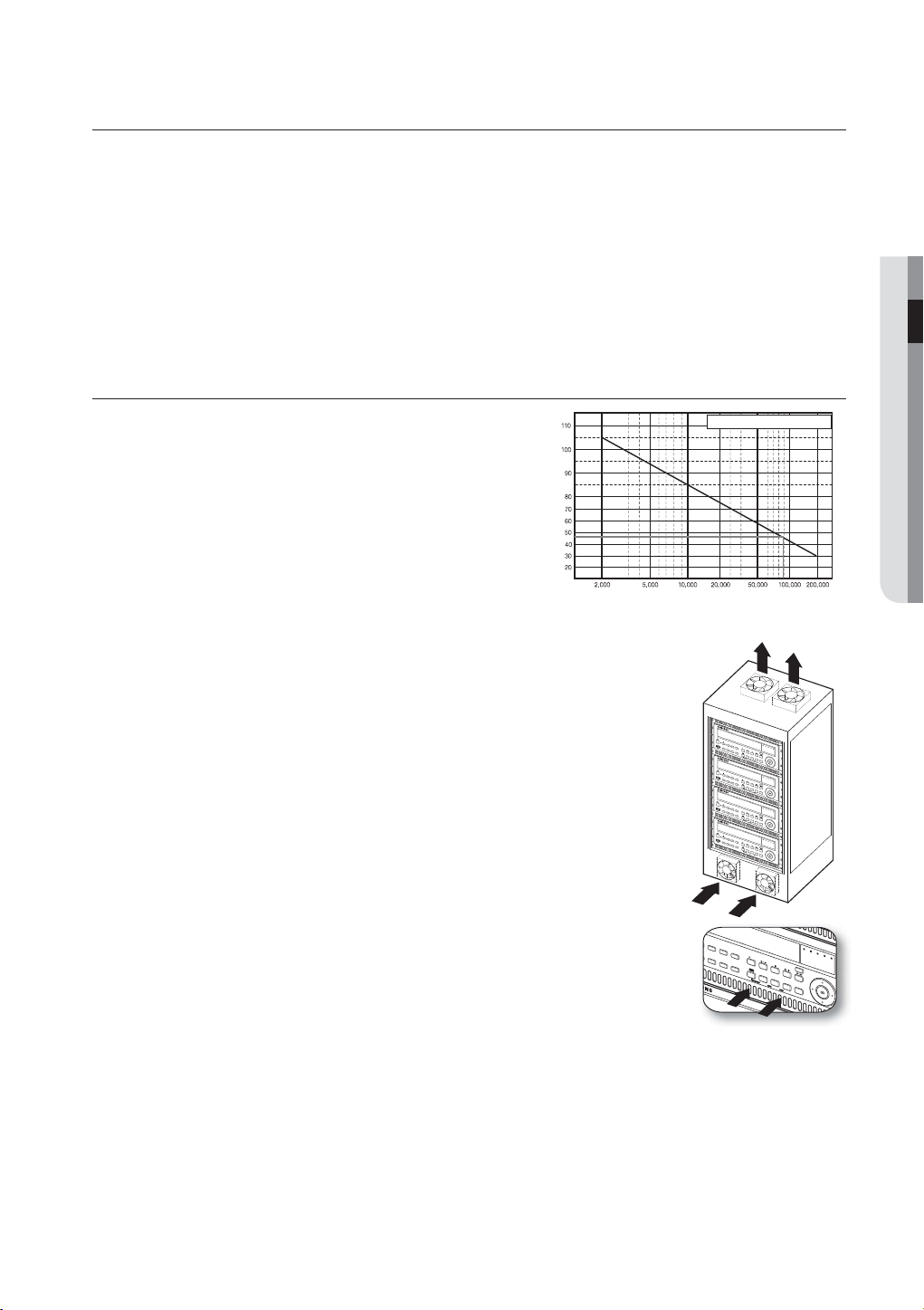
CHECKING THE INSTALLATION ENVIRONMENT
INSTALLATION
Samsung Digital Video Recorder (“DVR” hereinafter) is a
state-of-art security device, and contains mass storage hard
Temperature
Unit: ºC
One Year: 24HR X 365 DAY =8,760 HR
disk(s) and critical circuits inside.
When the temperature rises inside the product, the product
may breakdown and the product life be shortened. Please
pay attention to the following recommendations before
installation.
Life (Unit: HOURS)
[Figure 1]
The followings are the recommendations when Samsung DVR is installed on a rack.
1. Please ensure that the rack inside is not sealed.
2. Please ensure the air is circulated through the inlet/outlet as shown in the picture.
3. If the DVR or other devices on a rack is to be stacked as in the picture, provide a
suitable space or install a ventilating opening for air circulation.
4. For natural air convection, place the inlet at the bottom of the rack and the outlet on
top.
5. It is strongly recommended that a fan motor is installed at the inlet and the outlet for air
circulation. (Please fit a filter at the inlet to screen dust or foreign substances.)
6. Please maintain the temperature inside the rack or surrounding areas between 0°C ~
DIGITAL VIDEO RECO
RDER SRD-470D
MODE
AUDIO
AL
A
ALARM
RM
HDD
1
N
E
T
W
O
RK
B
2
REC
AC
KUP
REC
3
4
ZOOM
FREEZE
SEARCH
T
ELE
MENU
WIDE VIEW
DIGITAL
VIDEO RECORDER
SRD-470D
MODE
AUDIO
ALAR
A
M
LARM
HDD
1
N
E
T
W
O
RK
BA
2
REC
C
KUP
R
EC
3
4
ZOOM
FREEZE
SEARCH
T
ELE
MENU
WID
E
VIE
W
DIGITAL VIDEO RE
CORDER
SRD-470D
MODE
AUDIO
ALAR
ALARM
M
HDD
1
N
E
T
WORK
B
2
REC
AC
KUP
RE
C
3
4
ZOOM
FREEZE
SEARCH
T
E
LE
MENU
WIDE V
IEW
DIGITAL VIDEO RECORDER
SRD-470D
MODE
AUDIO
AL
A
ALARM
R
M
HDD
1
N
E
T
W
O
RK
B
2
REC
AC
KUP
REC
3
4
ZOOM
FREEZE
SEARCH
TELE
MENU
WIDE
VIEW
40°C (32°F ~ 104°F) as shown in the figure 1.
Rack Mount Instructions - The following or similar rack-mount instructions are
included with the installation instructions :
A) Elevated Operating Ambient - If installed in a closed or multi-unit rack assembly, the
operating ambient temperature of the rack environment may be greater than room
ambient. Therefore, consideration should be given to installing the equipment in an
environment compatible with the maximum ambient temperature (Tma) specified by
the manufacturer.
[Figure 2]
B) Reduced Air Flow - Installation of the equipment in a rack should be such that the
amount of air flow required for safe operation of the equipment is not compromised.
C) Mechanical Loading - Mounting of the equipment in the rack should be such that a hazardous condition is
not achieved due to uneven mechanical loading.
D) Circuit Overloading - Consideration should be given to the connection of the equipment to the supply circuit
and the effect that overloading of the circuits might have on overcurrent protection and supply wiring.
Appropriate consideration of equipment nameplate ratings should be used when addressing this concern.
E) Reliable Earthing - Reliable earthing of rack-mounted equipment should be maintained. Particular attention should
be given to supply connections other than direct connections to the branch circuit (e.g. use of power strips).
English _13

installation
HDD ADDITION
You can install additional HDDs.
Make sure to unplug the power cord from the wall outlet to prevent possible electric shock, injury or product
damage.
Please consult your provider for further information on HDD installation since improper installation or settings may
damage the product.
Number of HDDs supported : SRD-470 : Default 1 HDD + Up to 1 HDD added
SRD-470D : Default 1 HDD
Make sure to unplug the power cord from the wall outlet before proceeding with the installation.
Cautions for data loss (HDD care)
J
Please pay attention so that the data inside the HDD is not damaged.
Before adding a HDD, please check the compatibility with this DVR product.
HDD is vulnerable to malfunction due to its sensitive nature especially against shock when operating.
Please ensure that the HDD is free from such shock.
We are not liable for any damage to the HDD incurred by user’s carelessness or miss use..
Cases might cause damage to HDD or recorded data
To minimize the risk of data loss from a damaged HDD, please backup data as often as possible.
Data may be lost due to external impacts during disassembly or installation of the DVR.
HDD may be damaged if the DVR is suddenly stopped by a power cut or power off during operation.
HDD or files stored inside may be damaged if the main body is moved or impacted during the HDD operation.
Cautions when adding a HDD
1. When adding a HDD, ensure that the cable does not get caught or the insulation does not come off.
2. Pay attention so as not to lose the disassembly screws or accessories.
If the screws or accessories are not put together correctly, the product may breakdown or not operate properly.
3. Please check the HDD compatibility before adding a HDD.
Please contact your nearest dealer to obtain the list of compatible devices.
14_ installation
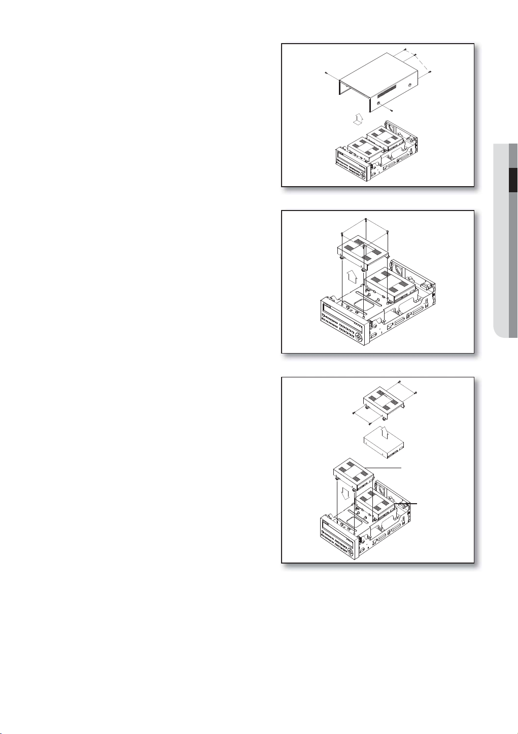
1. First, loosen the screws on both sides and remove
the cover.
2. Loosen the left and right screws on the lower hard
disk bracket to remove it.
INSTALLATION
3. Insert the additional hard disk into the bracket and
fix it using the provided screws.
Hard disk bracket
Master hard disk
English _15
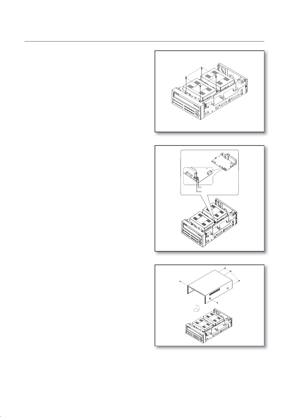
installation
4. Insert the bracket where the additional hard disk is
inserted into the lower bracket and fix it using the
provided screws.
5. When done, connect the power cable and connect
the signal cable (SATA cable) to the connector for
the main board.
SATA 2
SATA 1
6. Check if the connectors are properly connected
and there is no problem with wiring, and close the
cover and fix it with screws.
16_ installation
connecting with other device
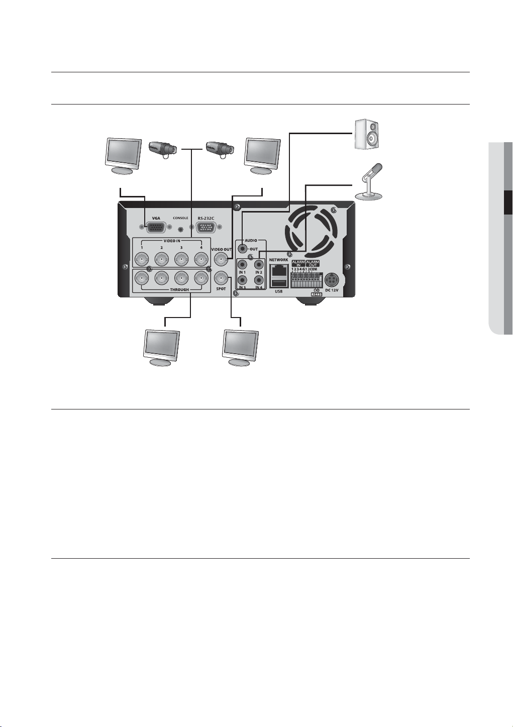
CONNECTING THE VIDEO, AUDIO, AND MONITOR
VIDEO OUT(VGA)
MONITOR
VIDEO IN
VIDEO OUT
SPOT OUT
AUDIO OUT
AUDIO IN
CONNECTING THE USB
1. By factory default, a USB port is provided for external connection.
2. You can connect a USB HDD, USB CD/DVD player, USB memory or mouse to the USB port.
3. If a USB HDD is connected to the system, recognition and settings are available in “Menu > Setting the Device >
Storage Device”. (Page 44)
4. This product supports hot-plugging, which connects/removes the USB device during the system operation.
CONNECTING WITH OTHER DEVICE
If you use the USB device for Backup purposes, format it with FAT32 on PC if it is not formatted on the DVR.
J
CONNECTING POS DEVICE
1. You can connect a POS device to the RS-232C port on the product’s rear side when you connect it directly with
a RS-232C cable.
2. Connection setup for the RS-232C port is available in “Menu > Device > POS Devices”, press the
<POS Device Setup> button and set <Baudrate, Parity, Data, Stop bit and Transfer Type>. (Page 47)
English _17
connecting with other device
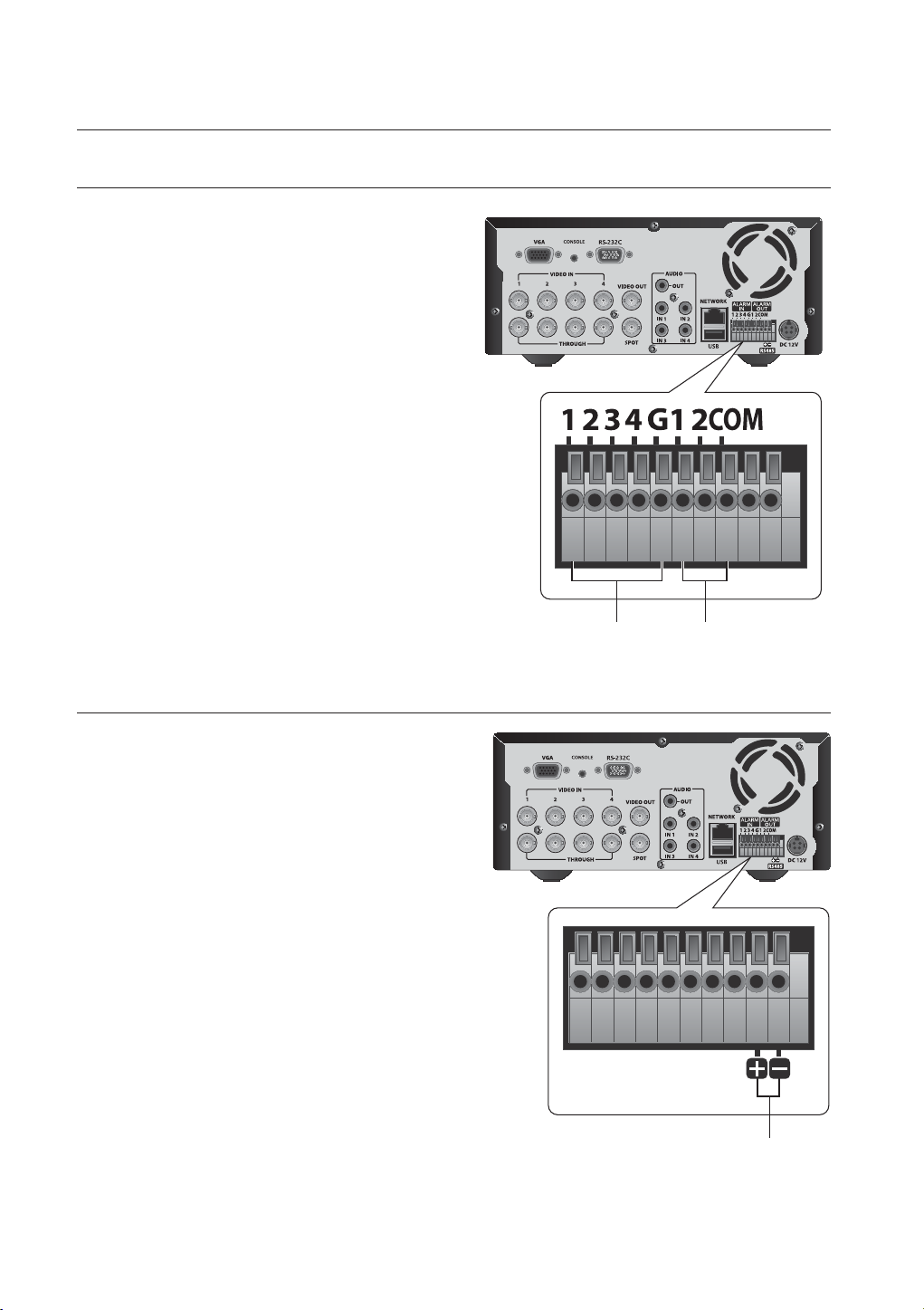
CONNECTING THE ALARM INPUT/OUTPUT
Connecting the alarm input signal
Connection port for the alarm input signal.
Connect one strand of the sensor signal line (two
strands) to the alarm input port and connect the other
to the [G] port.
Connecting the alarm output signal
Connection port for the alarm output signal.
Connect one strand of the sensor signal line
(two strands) to the alarm output port and connect
the other to the [COM] port.
ALARM IN ALARM OUT
CONNECTING THE RS485 DEVICE
Connect the rear [RS485 +, –] ports to the external device.
You can connect and control the PTZ camera which
M
supports the RS485 communication.
Check if the RS485 device is compatible with the
product first.
Pay attention not to change the polarity (+/-) of the
RS485 device when connecting it.
Depending on camera’s type, connection polarity can
be different.
For further information, refer to the respective PTZ
Camera’s documentation.
RS485
18_ connecting with other device
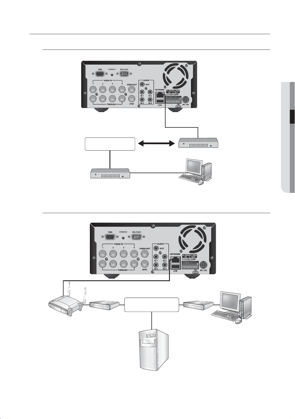
CONNECTING THE NETWORK
Connecting to Internet through Ethernet (10/100/1000BaseT)
RJ-45 Ethernet Cable
(Direct Cable)
CONNECTING WITH OTHER DEVICE
NETWORK
Hub/Switcher
Back Bone
Connecting to the Internet using the router
NETWORK
Hub/Switcher
Windows
Network Viewer
Router
xDSL or Cable
Modem
xDSL or Cable
Modem
External Remote
PC
DDNS Server
(Data Center)
English _19
connecting with other device
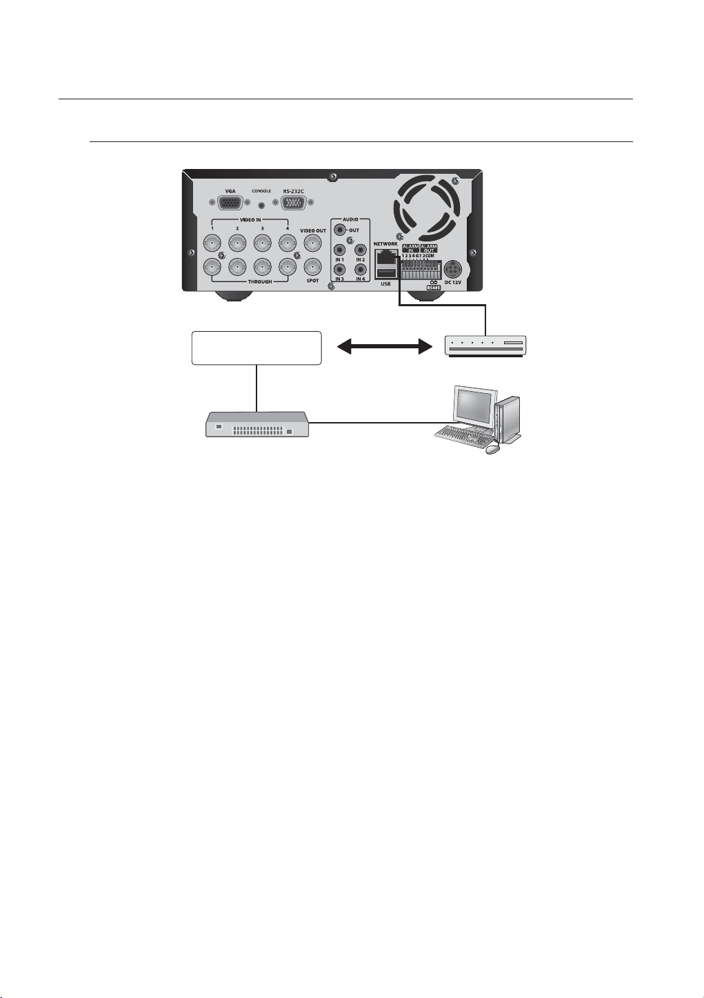
Connecting to Internet through ADSL
RJ-45 Ethernet Cable
(Direct Cable)
INTERNET
Hub/Switcher
Phone(ADSL) Line
ADSL MODEM
Windows
Network Viewer
20_ connecting with other device
live
GETTING STARTED
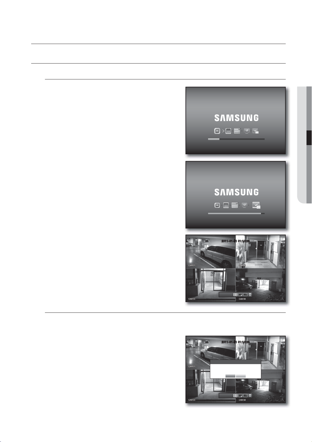
Starting the system
1. Connect the power cable of the DVR to the wall outlet.
2. Press the Power button on the front panel.
3. You will see the initialization screen.
The initialization process will last about 1 minute.
If a new HDD is installed, the initialization process may
take longer.
4. The live screen appears with a beep.
LIVE
REC
REC
2011-01-01 01:10:25
2011-01-01
01:10:25
Shutting Down the System
You can shut down the system only if you have logged into the DVR.
You require permission to shut down the system if you are not logged in as admin.
1. Press the [POWER] button on the remote control or the
front panel, or right-click to display the context sensitive
menu and select <Shutdown>.
2. The “Shutdown” confirmation window appears.
3. Use the arrow keys on the remote control or the front panel
to move to <OK> and press the [ENTER] button or click
<OK>.
The system will shut down.
For the permission management, refer to “Permission
M
Management > Setting Permissions”. (Page 37)
2011-01-01 01:10:25
Shutdown
2011-01-01
01:10:25
Are you sure to shutdown?
OK Cancel
English _21
live
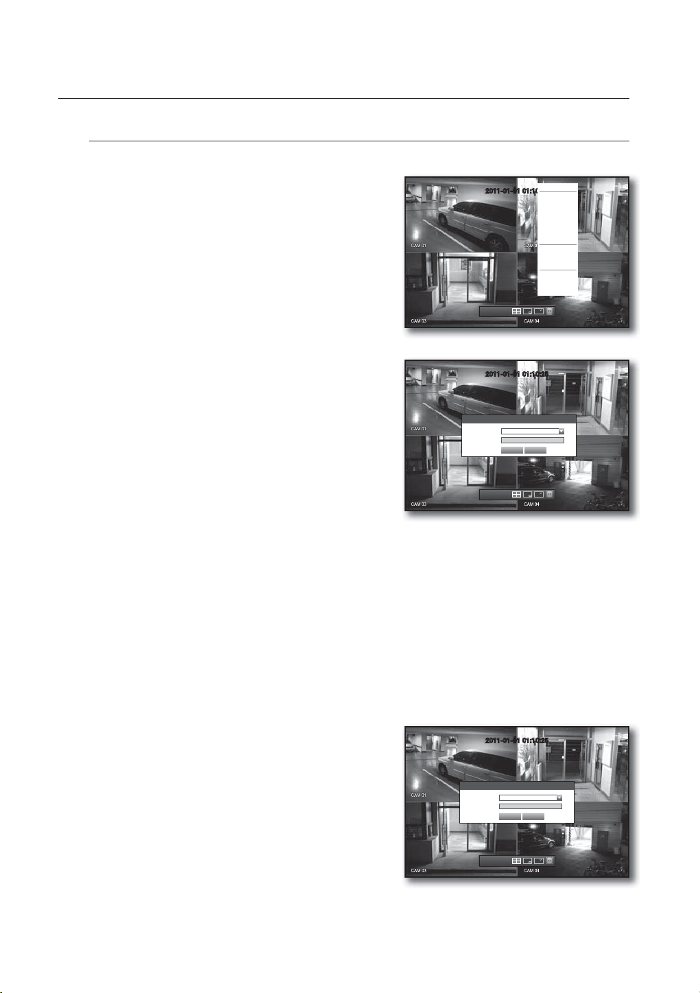
Login
To access a DVR or restricted menu, you should have logged in to the DVR.
1. In live mode, right-click any area of the screen.
You will see the context sensitive menu as in the right
figure.
2011-01-01 01:10:25
2011-01-01
01:10:25
Scene Mode
ZOOM
Audio Off
Freeze
Stop Alarm
Record
Play
Search
Backup
Main Menu
Shutdown
Hide Launcher
Login
2. Click <Login>.
The login dialog appears.
2011-01-01 01:10:25
You can also see the login dialog to access a desired menu
by pressing the [MENU] button on the remote control or
the front panel.
The login dialog will also appear if you press a menu button on
the remote control or the front panel of the DVR when the
Login
ID admin
Password
OK Cancel
corresponding menu requires logging in.
After logged in, press [RETURN] on the remote control to display
2011-01-01
01:10:25
the logout dialog.
By default, initial ID and password are set to “admin”, and “4321”.
The default password can be exposed to a hacking thread so it is recommended to change the password after
J
installing the product.
Note that the security and other related issues caused by the unchanged password shall be responsible for the user.
For the restricted permission, refer to “Permission Management > Setting Permissions”. (Page 37)
M
Locking All Buttons
This will restrict access to all buttons available in the DVR.
1. In Live mode, press buttons in the order of [STOP (@)]
[FREEZE][STOP (@)][FREEZE][MENU].
All buttons will be locked.
2. In the lock condition, press any button to display a dialog
where you are prompted to enter the password for
unlocking the buttons.
The button lock will be released if you enter the admin
password.
2011-01-01 01:10:25
Key Lock Password
ID admin
Password
OK Cancel
2011-01-01
01:10:25
22_ live
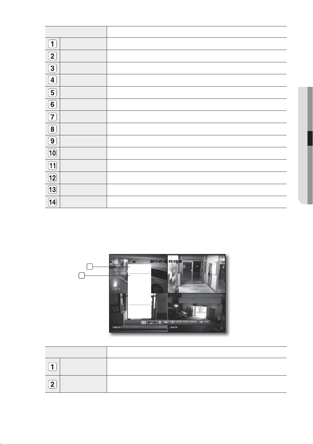
LIVE SCREEN CONFIGURATION
CAM 01
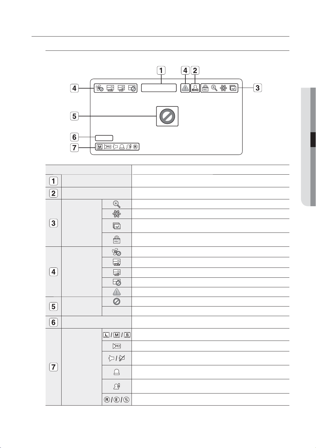
Icons on the Live Screen
You can check the status or operation of the DVR with the icons on the live screen.
2011-01-01 00:00:01
CAM 01
Name Description
Current Date, Time
Login Information
Displays the current time and date.
When you are logged in, the “LOG ON” icon will be displayed.
Displayed if the zoom function is activated.
Displayed if you press the Pause button.
Screen Mode
Displayed in Auto Sequence mode where all channels are switched at the
specific time interval.
Displayed if the recording is in process.
M To cancel the recording, enter the password.
Displayed if there is a problem with the cooling fan.
Displayed if the HDD is full and the DVR has an insufficient space to record.
System Operation
Displayed if no HDD is installed or the existing HDD should be replaced.
Displayed if the HDD needs a technical examination.
Displayed if a new firmware is found from the network.
Video Input Status
Displayed if no input is entered in the condition that the camera is set to <ON>.
Nothing will be displayed on the screen if the camera is set to <OFF>.
LIVE
Camera Name/ Channel
Camera Operation
Displays the camera name and the changed channel, if any.
Displays the resolution of the recording screen. (Page 52)
Displayed in PTZ setting, and highlighted yellow if PTZ is in operation.
Displays AUDIO ON/MUTE.
Not displayed in video mode if deactivated.
If the sensor is set to <ON>, the input signal will be displayed on the screen of
the connected channel.
Displayed if a motion detected in the condition that the motion detection is set to
<ON>.
Displays the current record mode from Record/Event/Schedule.
English _23
live
Error Information
• If the internal HDD is not connected, the “NO HDD”( ) message will appear; if there occurs a problem,
you will see the “HDD FAIL”(
service center for assistance as this may cause a failure of recording, playback or backup.
• If the cooling fan does not work properly or has a problem, the <Fan Information> window will appear and
the fan error icon (
) will be displayed on the top left corner. In this case, check to see if the internal fan
works.
As a fan error can shorten the product life, make sure you contact the service center for assistance.
If you see the fan error icon or No HDD, HDD FAIL icons on the screen, contact the service center for more details.
M
Live Screen Menu
In addition to the buttons on the front panel or the remote control, you can access a desired menu by rightclicking the mouse any area in live mode.
The context sensitive menu that appears by right-clicking the screen may differ, depending on the login/
logout, screen split mode and DVD operation mode.
Menu items of Search, Record, Backup, Shutdown and PTZ can be deactivated, depending on the user permission.
M
2011-01-01 01:10:25
2011-01-01
01:10:25
) message in the top left corner. In this case, make sure you contact the
Scene Mode
ZOOM
Audio Off
Freeze
Stop Alarm
Record
Play
Search
Backup
Main Menu
Shutdown
Hide Launcher
Login
2011-01-01 01:10:25
2011-01-01
01:10:25
Scene Mode
PTZ Control
ZOOM
Audio
Freeze
Stop Alarm
Record
Play
Search
Backup
Main Menu
Shutdown
Hide Launcher
Login
< Split Mode Menu >
< Single Mode Menu >
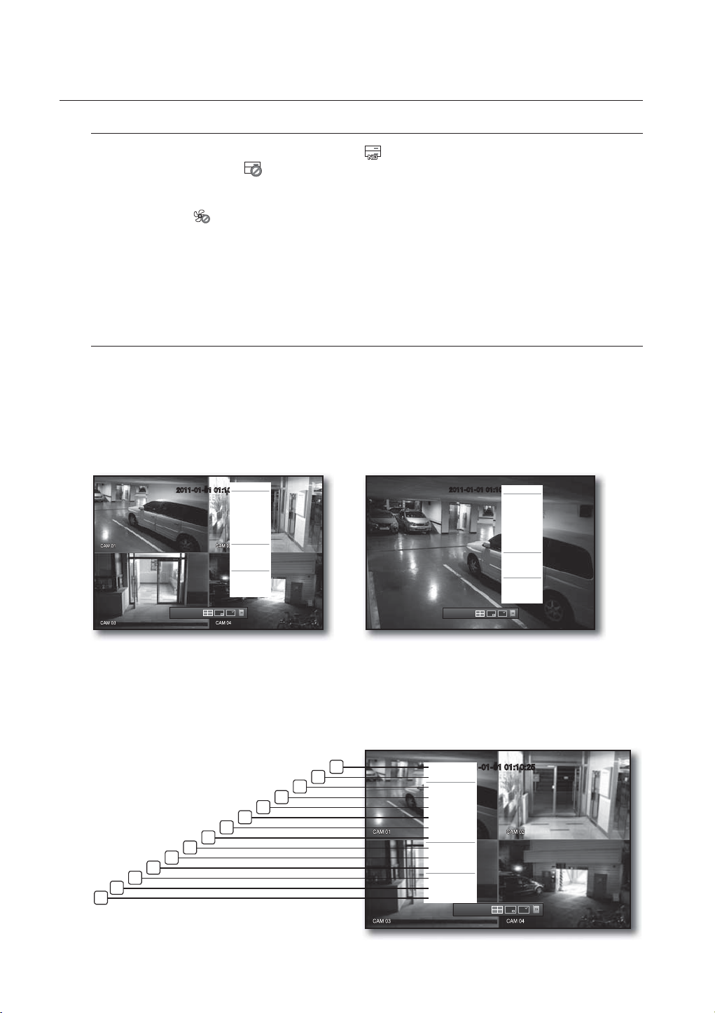
Split Mode Menu
The context sensitive menu in split mode differs, depending on the login/logout status.
Scene Mode
Spot Out
ZOOM
Audio Off
Freeze
Stop Alarm
Record
Play
Search
Backup
Main Menu
Shutdown
Hide Launcher
Logout
2011-01-01
01:10:25
14
24_ live
13
12
11
10
1
2
3
4
5
6
7
8
9
2011-01-01 01:10:25
Menu Description
Scene Mode Refer to “Live Mode”. (Page 27)
Spot Out Refer to “Spot Out”. (Page 29)
ZOOM Refer to “ZOOM”. (Page 29)
Audio On/Off Refer to “Audio ON/OFF”. (Page 30)
Freeze Refer to “Freeze”. (Page 30)
Stop Alarm Stops the alarm output and the event monitoring. Refer to “Event Monitoring”. (Page 30)
Record/Stop Starts/stops the standard recording.
Play Plays the search result (data). Refer to “Search & Play > Play”. (Page 69)
Search Refer to “Search & Play > Search”. (Page 66)
Backup Refer to “Using the DVR > Setting the Backup”. (Page 56)
Main Menu Accesses the main menu. Refer to the Using the DVR section. (Page 32)
LIVE
Shutdown
Show/Hide Launcher
Turns down the DVR.
Shows or hides the launcher. Refer to “View the Launcher Menu”. (Page 26)
Login/Logout You can log in or out.
Single Mode Menu
The single mode menu is available only in Single Mode.
The context sensitive menu for the One Channel mode, in Split mode is different from that of the Single mode.
1
2
Single
Spot Out
PTZ Control
ZOOM
Audio
Freeze
Stop Alarm
Record
Play
Shutdown
Hide Launcher
Logout
2011-01-01
01:10:25
Menu Description
2011-01-01 01:10:25
PTZ Alarm Freeze
Single
PTZ Control
Select and click a desired channel in Split mode to switch to the full screen of the selected
channel.
Accesses the PTZ Control menu. The PTZ menu is activated only in One-Channel Live mode.
(Page 64)
English _25
live
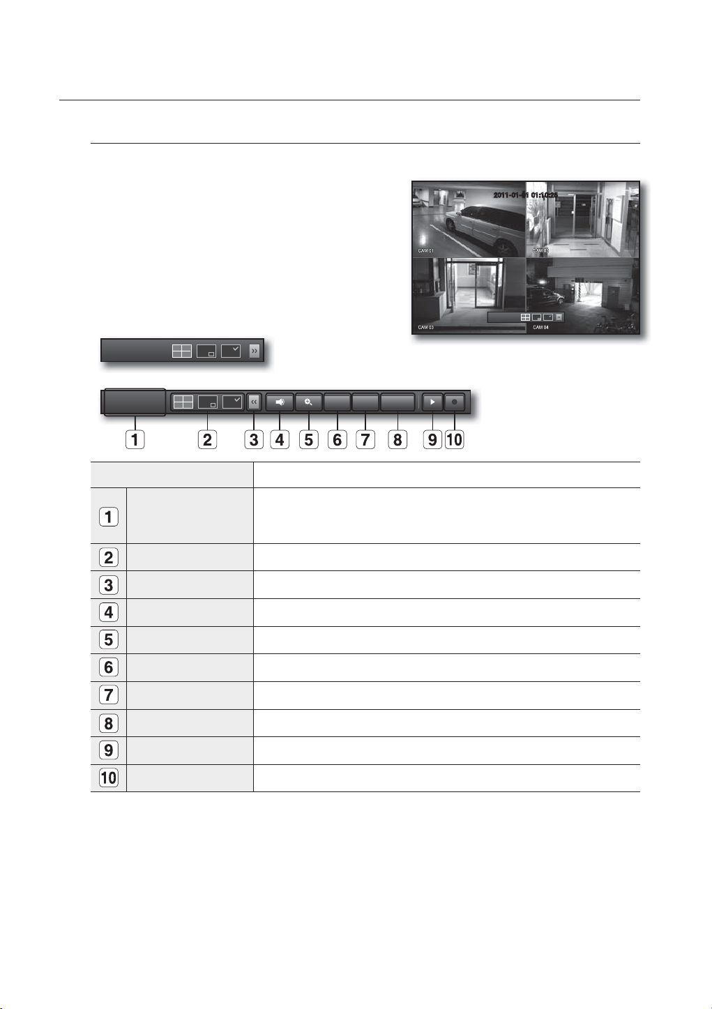
View the Launcher Menu
The Launcher menu appears on the bottom of the live screen.
1. In Live mode, right-click to display the context menu and
select <Show Launcher>.
2. Move the cursor to the bottom and click a desired item in
the Launcher menu.
If no input is entered for 10 seconds, the menu will disappear.
M
The Launcher menu can be accessed only by using the mouse.
2011-01-01
01:10:25
2011-01-01 01:10:25
2011-01-01
01:10:25
2011-01-01
01:10:25
Menu Description
Date/Time
Screen Mode Press this button to switch the screen mode in sequence.
Menu Expansion Button Click to display the hidden menu to the right.
Audio Turns ON/MUTE the sound of the selected channel.
Zoom Enlarges the selected area. This is available only in Single Live mode.
PTZ Runs the PTZ Control launcher.
Alarm Stops the alarm if it's activated.
Freeze Freezes the Live screen temporarily.
Play Enters Play mode if a file to play exist, and if not, enters Search mode.
Record Start/End recording the Live screen.
Displays the current time and date.
The indication of AM/PM is displayed if you set 12 hours for the time format in
“System > Date/Time/Language > Time”. (Page 32)
PTZ
Alarm Freeze
26_ live
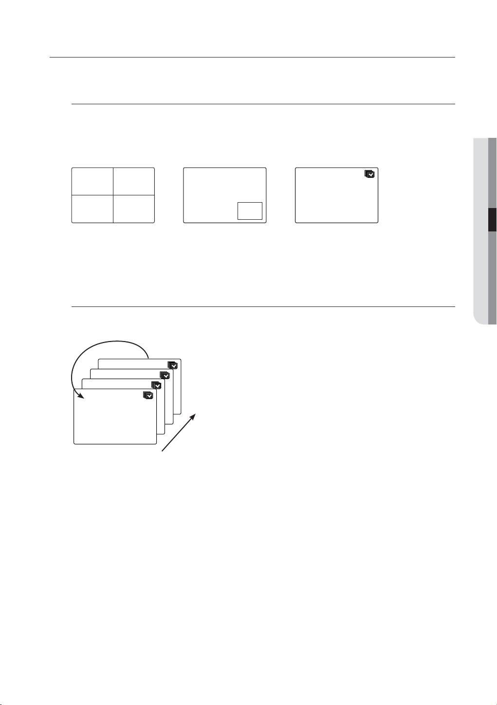
LIVE MODE
Displays 4 live video images in 3 different modes.
Switching the screen mode
To switch the split mode, select a screen mode in the launcher menu, or right-click to select a screen mode in
the context menu.
Press the [MODE] button on the front panel or the remote control to switch the mode in the sequence of the
launcher menu items.
CH1 CH2
CH3 CH4
4-split mode PIP Auto Sequence
CH1
Switching the screen automatically
With SRD-470/470D, you can display 4 live single screens in sequence.
CH2
CH1
LIVE
CH1
CH1
CH1
CH1
Single mode
In Single mode, If you have set <SEQ-Dwell Time> in “Setting the Device > Camera”, Auto Sequence will be
M
conducted at the set interval. (Page 42)
1
4
English _27
live
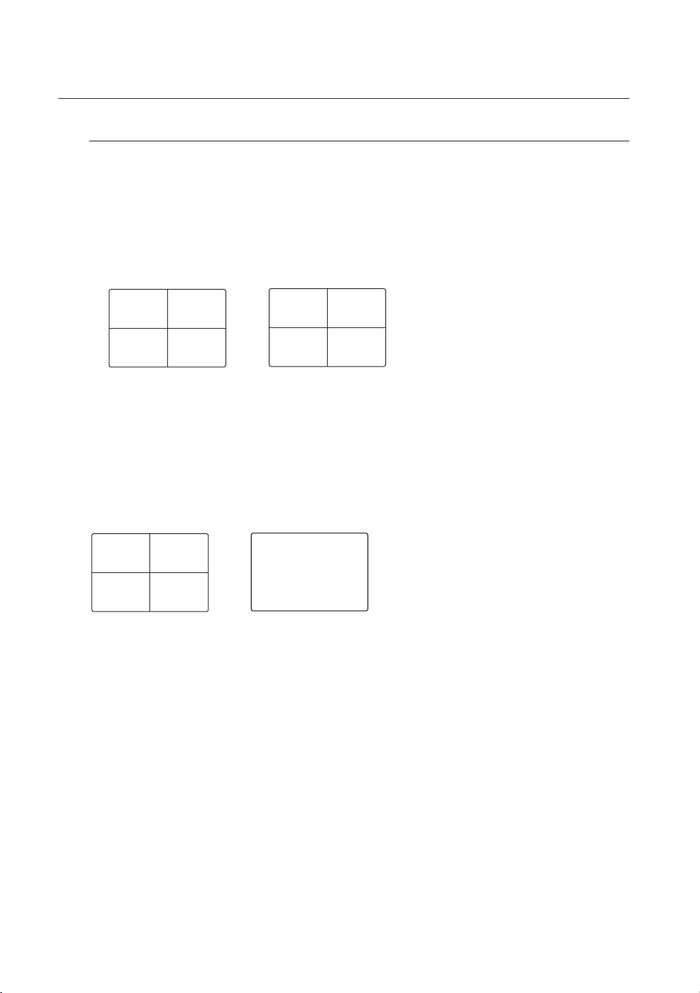
Channel Setting
You can display the channel in a desired area of a split screen.
1. Click a camera name to display a channel list where you can select a different channel.
2. Select a desired channel and click it.
The current channel will be switched to the selected one.
Use the cursor to select a channel to move, and drag and drop it to a desired channel; this can also
change the channel position.
Ex : if switching CH 1 to CH 4
CH1 CH2
CH4 CH2
CH3 CH4
Switching to Single Mode
When in split mode, select and double-click a desired channel to switch to its Single mode.
Press the number corresponding to a desired channel on the front panel or the remote control to switch to its
Single mode.
Refer to “Remote Control > Using the numeric buttons”. (Page 12)
Ex : If double-clicking CH 3 or pressing the number “3” on the remote control or the front panel.
CH1 CH2
CH3 CH1
CH3 CH4
CH3
28_ live
SPOT OUT
The Spot Out monitoring is independent of the Live mode, which monitors a specific channel through the Spot Out
port.
Selecting a Spot Out mode
If an event occurs such as sensor, motion or alarm from the Spot Out port in connection with a monitor, you
can select a output screen mode.
1. In Live mode, right-click any area on the screen.
The Live menu appears.
2. Click Spot Out.
Supports the Spot output in Single screen with Auto
Sequence mode.
The Spot output is supported only for a designated channel.
For the Spot Out port of a model, refer to “Part Names and
Functions (Rear)”. (Page 9)
Scene Mode
2011-01-01 01:10:25
Spot Out
Spot Out 1 Auto Sequence
ZOOM
Audio Off
Freeze
Stop Alarm
Record
Play
Search
Backup
Main Menu
Shutdown
Hide Launcher
Logout
2011-01-01
01:10:25
Single
CH1
CH2
CH3
CH4
< Multichannel Live Menu >
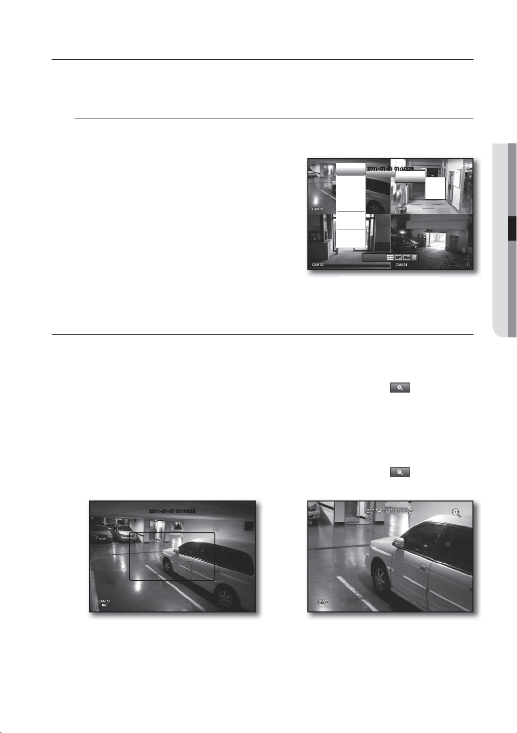
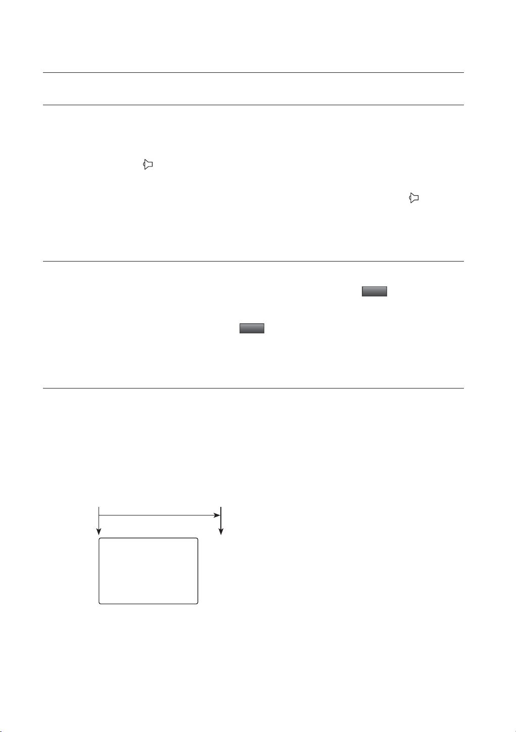
ZOOM
LIVE
This is available only in Single Live mode. In Single mode, select a desired area and use the Zoom function to
enlarge it twice.
1. Select <ZOOM> in the right-click menu.
Press the [ZOOM] button on the front panel or the remote control, or simply click <
> in the launcher
menu. The zoom box appears.
2. Use the direction keys, or drag and drop to specify an area to enlarge.
3. Press the [ENTER] button, or double-click the selected area to enlarge it twice.
In the enlarged image, use the direction buttons (◄ ►) on the remote control or the front panel to move the
enlarged area.
4. Press the [ZOOM] button on the front panel or the remote control, or simply click < > in the launcher
menu to release the zoom.
2011-01-01 01:10:25
English _29
live
AUDIO ON/OFF
You can turn the sound on/off corresponding to the channel in Live mode.
AUDIO ON/OFF in Single mode
Click the audio icon ( ) on the screen, or press the [AUDIO] button on the front panel or the remote control
to turn it on/off.
Only the channel where <AUDIO> is set to <ON> in “Device > Camera” displays the audio icon ( ) in Live mode
M
that you can use to turn the sound on/off.
FREEZE
This is available only in Live mode, this pauses playing the Live image temporarily.
1. Press the [FREEZE] button on the front panel or the remote control, or click <
menu.
The playback of the image is stopped temporarily.
2. Press the [FREEZE] button again, or click <
This will release the freeze.
Freeze
>.
Freeze
> in the launcher
EVENT MONITORING
This will display the channel in sync with a specific event (Sensor/Motion/Video Loss) if it occurs.
In “Monitor > Event Display”, set the event monitoring to ON/OFF and specify the event display time. (Page 48)
• If multiple events occur simultaneously, the screen will switch to a split mode.
- 2~4 events : 4-split mode
• If the second event occurs within the set time of <Event Display>, the first event will last until the second
one is terminated. (Page 48)
Ex : If you set <Event Display> to 5 seconds, and only one event occurs in CH 1.
Event occurrence 5 seconds
Stop alarm
CH1
30_ live
 Loading...