


Manual for SPW-B43143U WiFi module
1. Introduction
SPW-B43143U is a Wi-Fi module compliant with IEEE802.11 b.g.n MAC/baseband/radio optimized for low-
power applications. The core chipset is from Broadcom, part number BCM43143.
2. Hardware Architecture:
2.1 Main Chipset Information
Item Vendor Part Number
IEEE802.11 b.g.n
mac/baseband/radio
2.2 Circuit Block Diagram
The major internal and external block diagram of SPW-B43143U is illustrated in Figure 1-1.
Broadcom BCM43143
Figure 1-1 SPW-B43143U block diagram and System Interface
Version 1.0 Samsung Electronics page 1 of 7
2.3 RF Specification
All measurements are made under nominal power supply and room temperature 25 °C unless specified.
RF specification of SPW-B43143U was defined according to 802.11b/g mandatory
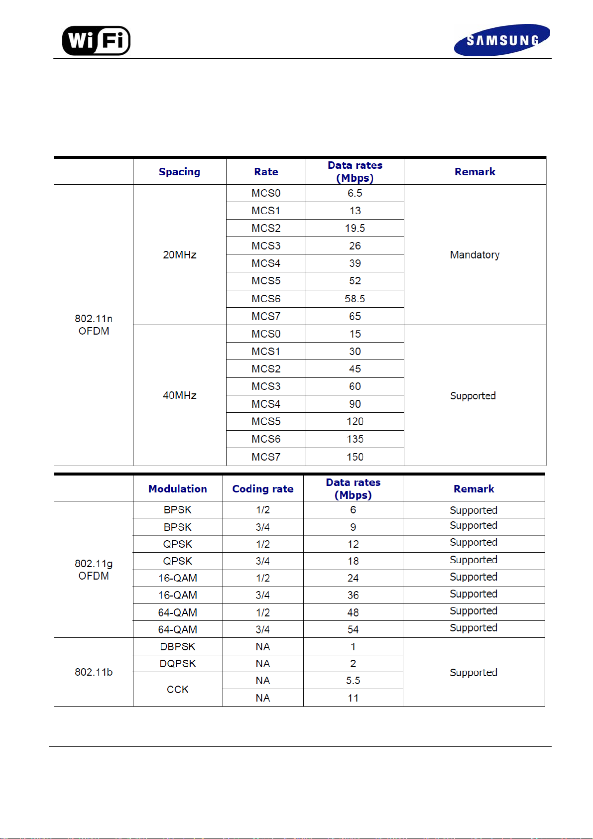
2.3.1 Supportable Modulation Scheme & Data Rates
Version 1.0 Samsung Electronics page 2 of 7

2.3.2 Module output power information
TX power
Data rate
2.4G
802.11 b 11Mbps +17dBm
802.11 g 54Mbps +14dBm
802.11 n 65Mbps (MCS7) +13 dBm
2.3.3 Channel & Center Frequency
Version 1.0 Samsung Electronics page 3 of 7

3. Operational Description
SPW-B43143U is the 802.11 b/g/n RF Module that acts as a communication controller for users of a
wireless device to connect to WiFi TV. This uses IEEE 802.11n network with 13 channels at 2.4GHz
- Features
>IEEE 802.11 b/g/n client
> Band 2.4GHz
>Integrated PA, LNA
>Green Tx power saving mode
>Low power listen mode
>1T1R mode with support of 150Mbps PHY rate
>Security support for WFA WPA/WPA2 personal, WPS2.0, WAPI
>Host interface : USB2.0 High-speed
- Time base of the RF frequency
For IF and RF frequency, a crystal(20MHz) is a clock reference.
- Synthesizer
Synthesizer inside Transceiver. Internal voltage controlled oscillator (VCO) provides the desired LO
signal base on the phase-locked loop (PLL) with a relatively wide tuning range for this application.
- Transmission
Base-band Processing (BBP) IC has DSSS (BPSK/QPSK/CCK) and OFDM
(BPSK/QPSK/16QAM/64QAM) modulation function, it provides transmission data rate are 1, 2, 5.5, 11
Mbps on DSSS and 6, 12, 18, 24, 36, 48, 54 Mbps on OFDM. Digital data signal will be converted to
analog (TX IQ) signals through DAC in BBP IC, TX IQ pass through to low pass filter. TX I/Q signal
use direct conversion (zero-IF) architecture converter to generate carrier frequency signal. Transceiver
IC and internal PA magnify output power.
- Receiver
Reverse direction isolation of LNA inside Transceiver IC suppresses unwanted radiation. Then RF
signal will be directly down to IF signal (RX IQ) and high frequency spurious emissions are suppressed by
LPF. At last RX IQ signal will be demodulated digital data.
- Power Control Level
It uses open-loop power control function to limit RF output power level using a calibration file.
- Integrated Network Processor
Network processor manages Wi-Fi link operations. The network processor code is loaded automatically
from a ROM. The network processor is optimized for energy efficient communications
Version 1.0 Samsung Electronics page 4 of 7

- Product Details
> Data Modulation OFDM (BPSK / QPSK / 16QAM / 64QAM)
> Frequency Range 2412-2462MHz
4. Notice
_ FCC Statement
This device complies with Part 15 of the FCC Rules. Operation is subject to the
following two conditions:
(1) This device may not cause harmful interference, and
(2) This device must accept any interference received including interferenc e that cause undesired
operation.
_ Warning
Any changes or modifications NOT explicitly APPROVED by Samsung Electronics Co.,
Ltd. could cause the SPW-B43143U module to cease to comply with FCC ru les part 15,
and thus void the user's authority to operate the equipment.
_ RF-exposure statement
These modular transmitters, SPW- B43143U , comply with FCC radiation exposure limits
set forth for an uncontrolled environment. The SPW-B43143U should be installed and
operated with minimum distance 20cm between the antenna and the body of the user or
nearby persons. The OEM integrator has to be aware not to prov ide information to the
end user regarding how to install or remove this RF module in the users manual of the
end product which integrate this module.
This device is intended only for OEM integrators under the following co nditions:
1) The antenna must be installed such that 20 cm is maintained between the antenna
and users, and 2) The transmitter module may not be co-located with any other
transmitter or antenna.
As long as the 2 conditions above are met, further transmitter testing will not be required.
However, the OEM integrator is still responsible for testing their end product for any
additional compliance requirements required with this module installed (for example,
digital device emissions, PC peripheral requirements, etc.).
IMPORTANT NOTE: In the event that these conditions cannot be met (for example
certain laptop configurations or co-location with another transmitter), then the FCC
authorization is no longer considered valid and the FCC ID and IC number cannot be
used on the final product. In these circumstances, the OEM integrator will be
responsible for re-evaluating the end product (including the transmitter).
_ Antenna
These modular transmitters are for OEM integrations only. The end-user pro duct will be
installed in such a manner that only the authorized antennas are used.
Version 1.0 Samsung Electronics page 5 of 7

FCC Information to User
This equipment has been tested and found to comply with the limits for a Class B digital device, pursuant to Part
15 of the FCC Rules. These limits are designed to provide reasonable protection against harmful interference in
a residential installation. This equipment generates, uses and can radiate radio frequency energy and, if not
installed and used in accordance with the instructions, may cause harmful interference to radio communications.
However, there is no guarantee that interference will not occur in a particular installation. If this equipment does
cause harmful interference to radio or television reception, which can be determined by turning the equipment
off and on, the user is encouraged to try to correct the interference by one of the following measures:
• Reorient or relocate the receiving antenna.
• Increase the separation between the equipment and receiver.
• Connect the equipment into an outlet on a circuit different from that to which the receiver is con-nected.
• Consult the dealer or an experienced radio/TV technician for help.
Caution
Modifications not expressly approved by the party responsible for compliance could void the user’s authority to
operate the equipment.
FCC Compliance Information : This device complies with Part 15 of the FCC Rules. Operation is subject to
the following two conditions: (1) This device may not cause harmful interference, and (2) this device must
accept any interference received, including interference that may cause undesired operation
Version 1.0 Samsung Electronics page 6 of 7

IMPORTANT NOTE:
FCC RF Radiation Exposure Statement:
This equipment complies with FCC RF radiation exposure limits set forth for an uncontrolled environment. This
equipment should be installed and operated with a minimum di stance of
20 centimeters between the radiator and your body.This transmitter must not be co-located or operating in
conjunction with any other antenna or transmitter.
“This device complies with Industry Canada licence-exempt RSS standard(s).
Operation is subject to the following two conditions:
(1) this device may not cause interference, and
(2) this device must accept any interference, including interference that may cause undesired operation of the device.”
Le présent appareil est conforme aux CNR d'Industrie Canada applicables
aux appareils radio exempts de licence. L'exploitation est autorisée aux
deux conditions suivantes : (1) l'appareil ne doit pas produire de
brouillage, et (2) l'utilisateur de l'appareil doit accepter tout brouillage
radioélectrique subi, même si le brouillage est susceptible d'en
compromettre le fonctionnement.
Version 1.0 Samsung Electronics page 7 of 7
 Loading...