

Before installing and operating this product,
please read this manual thoroughly.
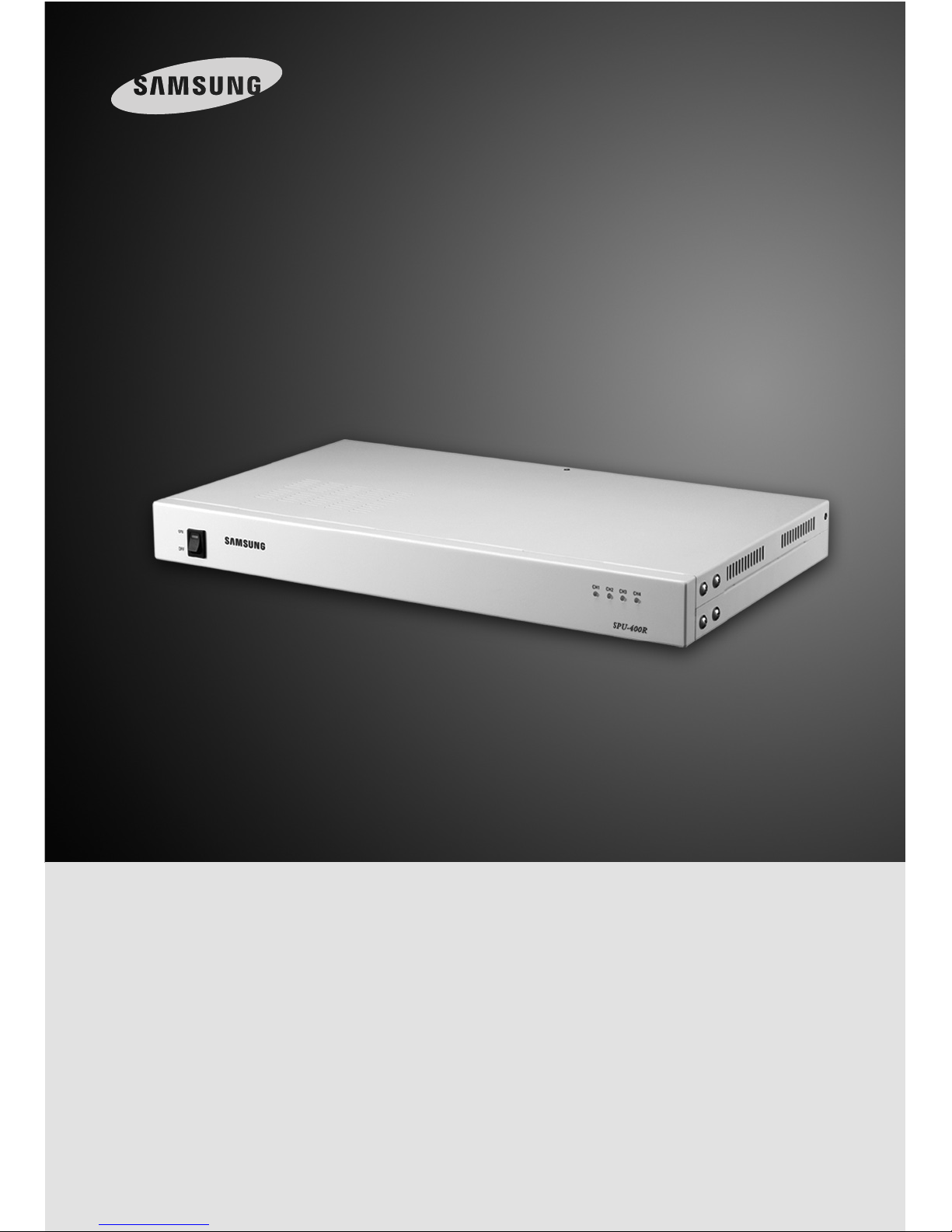
4CH UTP Receiver SPU-400R
User Guide
ENGLISH

4CH UTP Receiver User Guide
2
4CH UTP Receiver User Guide
3
Table of Contents
Before installing this product, please read the following cautions and warnings carefully.
Do not install the product in the following locations.
■ Places under extremely high or low temperature conditions
Use this product under temperature conditions only between -10° and +10°~50℃ to
prevent low performance and product malfunctions.
■ Places exposed to rain, snow, or high humidity
Avoid water and moisture leakage into the product; it may cause the product to malfunction.
■ Places containing or exposed to oil and gas
Oil, moisture, and gas leakage into the product may cause product malfunctions.
■ Places exposed to vibration and shock
Vibration and shock may cause product malfunctions.
■ Places under direct sunlight or exposed to outdoor weather conditions
Direct sunlight and severe weather conditions may cause product malfunctions.
■ Places exposed to radio waves (RF) or near power cables
Radio communication devices and electromagnetic waves from power lines may cause
product malfunctions.
■ Do not disassemble the product or allow foreign objects to get into the product.
Disassembly of the product or insertion of foreign objects such as metal may cause break
or damage the unit.
■Make sure to turn off the product prior to installation.
Before installing your product, please check its voltage rating and then turn on the power
switch.
■Do not subject the product to physical shock or exert excessive force to operate the
product. Shocks and excessive force on the components such as circuits may break or
seriously damage the unit.
Thank you for purchasing a Samsung Techwin product. Before attempting to
connect or operate this product, please read this instruction book carefully and
save it for future use.
If you find this manual too difficult to understand, or experience problems with
installing or using it, please contact our service center or sales department for
assistance.
Cautions for Installation
Cautions for Use
1. Product Introduction ……………………………………………… 4
1-1. Overview …………………………………………………… 4
1-2. Product Features ……………………………………………… 4
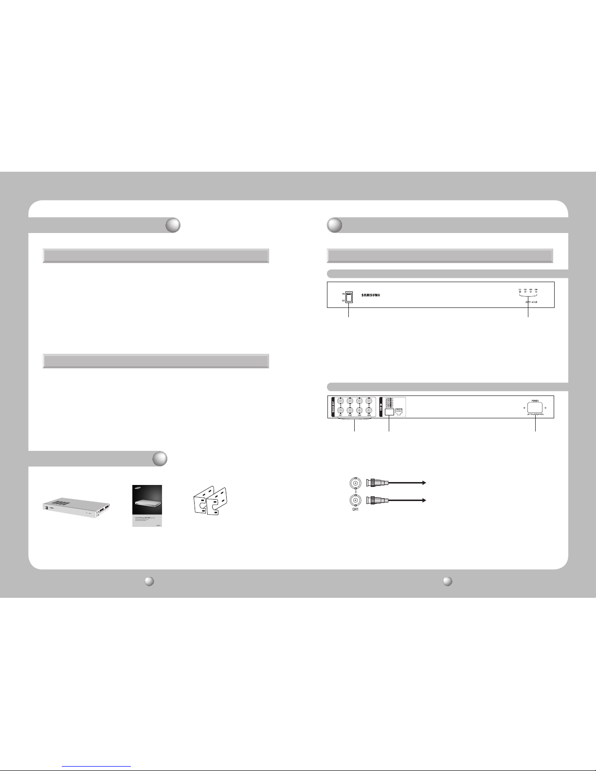
2. Package Contents ………………………………………………… 4
3. Product Parts and Peripheral Device Connection ………………… 5
3-1. Part Names and Functions …………………………………… 5
3-1-1. Front …………………………………………………………… 5
3-1-2. Back …………………………………………………………… 5
3-2. Installing the SPU-400R and Connecting UTP Cable …………… 6
3-2-1. The SPU-400-Side UTP Cable …………………………………… 6
3-3. SPU-400R Connector Wiring Chart …………………………… 7
3-4. Connecting & Operating the SPU-400R ………………………… 7
3-5. Connecting Peripheral Devices ………………………………… 8
4. Product Specifications …………………………………………… 9
5. Product Warranty ……………………………………………… 10
4CH UTP Receiver User Guide
4
4CH UTP Receiver User Guide
5
1. Product Introduction
2. Package Contents
The SPU-400R is a 4-channel UTP cable transmission receiver with auto level adjustment that
receives 4 video signals via a UTP cable from a camera, and then converts them to CVBS video
signals to transmit to a DVR or monitor. Equipped with 2 output ports, this receiver can divide and
transmit CVBS video signals to 2 different end devices. Containing 4 channels in a U-type steel
chassis, the SPU-400R is ideal for a facility that uses both coaxial and UTP cables, and to
transmit video signals to a moderate or long distance, up to 1km based on the color signal
transmission rate. This high performance receiver is programmed to automatically adjust the
distance of video signal transmission for your convenience, eliminating the hassle of adjusting the
A/F level manually.
- Active-type 4-channel UTP receiver with superb noise reduction capability.
- Transmits video signals up to 1 km based on the color signal transmission via CAT.5 UTP cable.
(When used in conjunction with our UTP cameras: the SUB-2000, SUD-2080/2080F, or SPU100TR).
- Programmed to auto-adjust video signals without changing A. level (video synchronization signal
level) and F. level (color signal level) manually.
- Automatically detects and compensates for NTSC / PAL signal types.
- Video signal loss check per channel (Normal: Green, Loss: Red).
1-1. Overview 3-1. Part Names and Functions
1-2. Product Features
3-1-1. Front
3-1-2. Back
① Power ON Switch
② Status LED for Video Signals from UTP Cable
- Green : Normal (Valid video signal)
- Red : Loss (No signal detected)
※ Recommended UTP Cameras: SUB-2000, SUD-2080/2080F
① BNC-F : Video Signal Output Terminal
- Both terminals are used to transmit the same signals; you do not need a separate signal
distributor to send the signals to 2 different devices.
② RJ-45 : Input Terminal for Video Signals from UTP Cable
③ AC Inlet: AC Input Terminal
- 100 ~ 240V AC, 50/60 Hz
To Video Matrix
To DVR
CH1
CH2
CH3
CH4
❶
SPU-400R
2
User Guide
3
19” Rack Mount
3. Product Parts and Peripheral Device Connection
① ②
① ② ③

4CH UTP Receiver User Guide
6
4CH UTP Receiver User Guide
7
3-2-1. The SPU-400R-Side UTP Cable
- Connect an RJ-45 plug to the UTP cable on the SPU-400 4-channel power supply.
- The following pin alignment complies with the communication cable standards and is
provided for your convenient installation.
RJ-45 Connector Wiring Chart for Video Input (SPU-400 ↔ SPU-400R)
- Connect an RJ-45 plug to the UTP cable on the SPU-400.
- Connect the RJ-45 plug to the UTP IN connector on the SPU-400R.
- Connect the AC power plug to the AC Inlet on the SPU-400R.
- Double check the UTP cable connection, and then turn on the power switch on the back of
the SPU-400R. The camera starts operating as the front status LED turns green.
- Turn on the power switch on the front panel of the SPU-400R, and check if the front LED of
a video channel turns green. Check the video signaling status at the DVR end.
- This equipment is indoor use and all the communication wirings are limited to inside of the
building
- Connect the RJ-45 plug to the UTP IN port on the SPU-400R.
- Please refer to the following pin description for the channel distribution.
- Please remember the description above may differ from your camera’s pin description.
3-2. Installing the SPU-400R and Connecting UTP Cable 3-3. SPU-400R Connector Wiring Chart
3-4. Connecting &Operating the SPU-400R
3. Product Parts and Peripheral Device Connection
No. Color Function
1 Orange + White Camera 2, (+)
2 Orange Camera 2, (-)
3 Green + White Camera 3, (+)
4 Blue Camera 1, (-)
5 Blue + White Camera 1, (+)
6 Green Camera 3, (-)
7 Brown + White Camera 4, (+)
8 Brown Camera 4, (-)
Copper Connector
UTP Coating

4CH UTP Receiver User Guide
8
4CH UTP Receiver User Guide
9
Controller
SUB-2000
SUD-2080F
SPU-400
SMX-25632
SPU-400R
DVR
300m(1000ft) or less
900m(3000ft) or less
3-5. Configuration
- Camera, Power Supply (SPU-400), UTP Video Receiver (SPU-400R) Wiring Example
- The SPU-400’s DATA port can be used in conjunction with a UTP cable to form a PTZ
controller. The SPU-400R can be used for dual video display with a DVR and video matrix
switcher.
- Power can be transferred up to 400m from the SPU-400 to a UTP camera. For video signal
transmission, up to 1,000m is available between a camera and the SPU-400R.
4. Product Specifications
Model 4CH Auto Receiver
Video Input Signal 1 Vp-p ~ 2 Vp-p, 51 Ω
Video Output Signal CVBS 1.0 Vp-p, 75 Ω
Video
Freq. Response DC to 5 MHz
Common-mode
Rejection
60 dB
Impedance
Coax, male BNC 75 ohms
UTP, RJ-45 50 ohms
Maximum Power Transfer Distance
(CAT.5e UTP Cable)
900m(3000ft)
Power
Display Switch LED
Input AC 100~240V, 50/60Hz
Connection Port
Video Input 1Port (RJ-45 )
Video Output Female BNC it has 2 outputs per Channel
LED Display
Red No signal detected
Green Valid video signal
Operating Temperature/Humidity -10ºC ~+50ºC / 0 ~ 80%
Material/Weight Steel / 2.7kg
Dimensions 430 (W) x 44 (H) x 250 (D) mm
3. Product Parts and Peripheral Device Connection
Rack Mount Instructions
1) Elevated Operating Ambient - If installed in a closed or multi-unit rack assembly, the operating
ambient temperature of the rack environment may be greater than room ambient. Therefore,
consideration should be given to installing the equipment in an environment compatible with
the maximum ambient temperature (Tma) specified by the manufacturer.
2) Reduced Air Flow - Installation of the equipment in a rack should be such that the amount of
air flow required for safe operation of the equipment is not compromised.
3) Mechanical Loading - Mounting of the equipment in the rack should be such that a hazardous
condition is not achieved due to uneven mechanical loading.
4) Circuit Overloading - Consideration should be given to the connection of the equipment to the
supply circuit and the effect that overloading of the circuits might have on overcurrent
protection and supply wiring. Appropriate consideration of equipment nameplate ratings
should be used when addressing this concern.
5) Reliable Earthing - Reliable earthing of rack-mounted equipment should be maintained.
Particular attention should be given to supply connections other than direct connections to the
branch circuit (e.g. use of power strips)."
Notes

4CH UTP Receiver User Guide
10
4CH UTP Receiver User Guide
11
5. Product Warranty
DECLARATION OF CONFORMITY
Application of Council Directive(s) 89 / 336 / EEC
Manufacturer's Name SAMSUNG TECHWIN CO., LTD
Manufacturer's Address SAMSUNG TECHWIN CO., LTD
42, SUNGJU-DONG CHANGWON-CITY,
KYUNGNAM, KOREA, 641-716
European Representative Name
European Representative Address
Equipment Type/Environment 4CH UTP Receiver
Model Name SPU-400R
Beginning Serial NO. S7090001
Year of Manufacture 2010. 01. 01
Conformance to EN EN55022:2006
EMC-Directive 89/336 EEC and 92/31/EEC
EN50130-4:2003
We, the undersigned, hereby declare that the equipment specified above conforms
to the above Directive(s).
Manufacturer SAMSUNG TECHWIN CO., LTD
Legal Representative in Europe
Signature Signature
Full Name BONJENG GU Full Name
Position QUALITY CONTROL MANAGER Position
Place CHANGWON, KOREA Place
Date 2010. 01. 01 Date
Class A Divice
NOTE
: This equipment has been tested and found to comply with the limits for class A
digital device, pursuant to part 15 of the FCC Rules. These limits are designed to provide
resonable protection against harmful interference when the equipment is operated in a
commercial environment. This equipment generates, uses, and can radiate radio
frequency energy and, if not installed and used in accordance with the instruction
manual, may cause harmful interference to radio communications. Operation of this
equipment in a residential area is likely to cause harmful interference in which case the
user will be required to correct the interference at his own expense.
CAUTION
: Changes or modifications not expressly approved by the manufacturer
responsible for compliance could void the user's authority to operate the equipment.

4CH UTP Receiver User Guide
12
4CH UTP Receiver User Guide
13
MEMO MEMO

4CH UTP Receiver User Guide
14
4CH UTP Receiver User Guide
15
MEMO MEMO

VAN 10.02
www.samsungtechwin.com
www.samsungcctv.com
•
SAMSUNG TECHWIN CO., LTD.
145-3, Sangdaewon 1-dong, Jungwon-gu, Seongnam-si Gyeonggi-do, Korea, 462-703
TEL : +82-31-740-8151~8 FAX : +82-31-740-8145
•
SAMSUNG TECHWIN EUROPE LTD.
Samsung House, 1000 Hillswood Drive, Hillswood Business
Park Chertsey, Surrey, UNITED KINGDOM KT16 OPS
TEL : +44-1932-45-5300 FAX : +44-1932-45-5325
•
SAMSUNG TECHWIN AMERICA Inc.
1480 Charles Willard St, Carson, CA 90746, UNITED STATES
Tol Free : +1-877-213-1222 FAX : +1-310-632-2195
www.samsungcctvusa.com
SALES NETWORK
 Loading...