

Samsung SPU-400 User Manual
Before installing and operating this product,
please read this manual thoroughly.
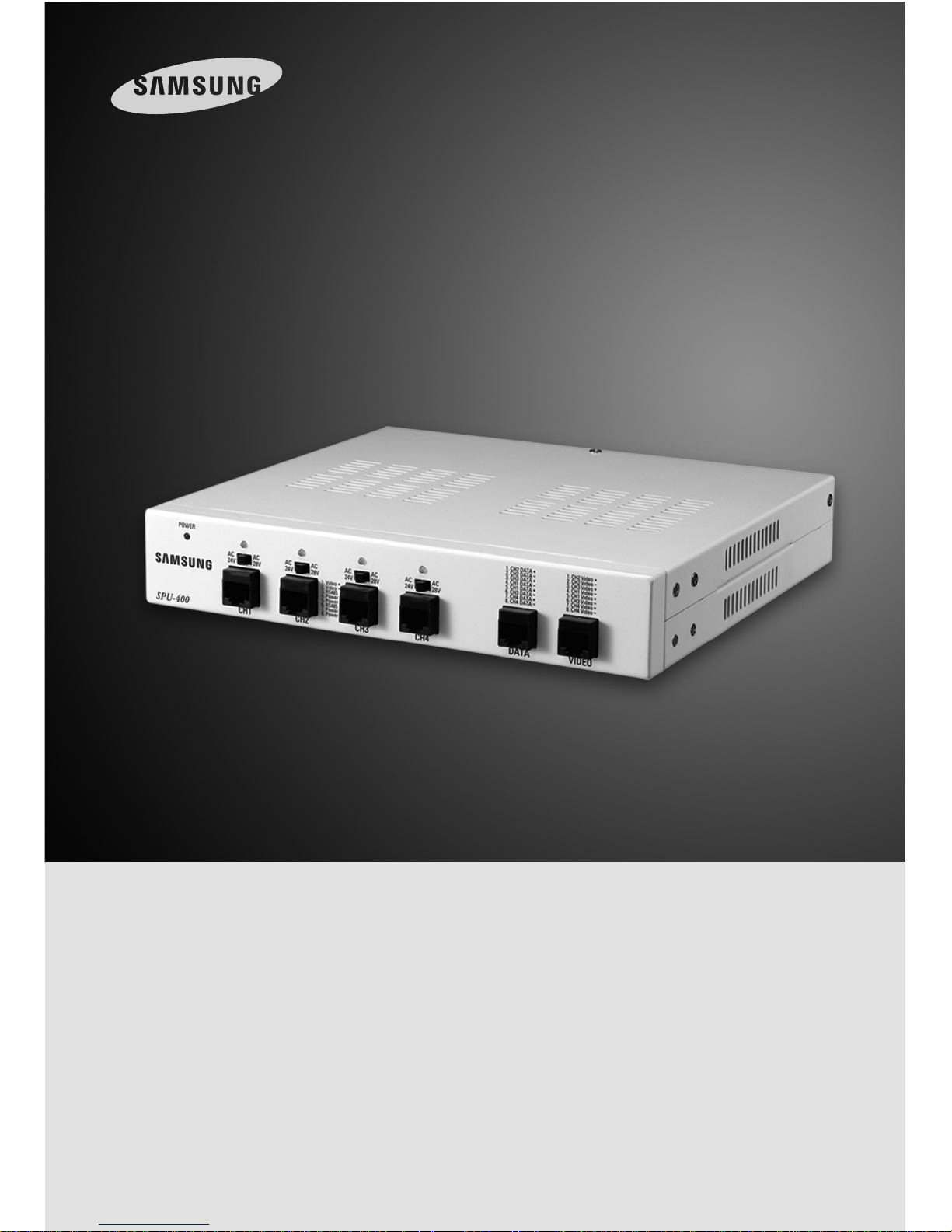
UTP Power Supply Hub SPU-400
User Guide
ENGLISH

UTP Power Supply Hub User Guide
2
UTP Power Supply Hub User Guide
3
Table of Contents
Before installing this product, please read the following cautions and warnings
carefully.
Do not install the product in the following locations.
■ Places under extremely high or low temperature conditions.
Use this product under temperature conditions only between -10° and +50° to prevent low
performance and product malfunctions.
■ Places exposed to rain, snow, or high humidity.
Avoid water and moisture leakage into the product; it may cause the product to malfunction.
■ Places containing or exposed to oil and gas.
Oil, moisture, and gas leakage into the product may cause product malfunctions.
■ Places exposed to vibration and shock.
Vibration and shock may cause product malfunctions.
■ Places under direct sunlight or exposed to outdoor weather conditions.
Direct sunlight and severe weather conditions may cause product malfunctions.
■ Places exposed to radio waves (RF) or near power cables.
Radio communication devices and electromagnetic waves from power lines may cause
product malfunctions.
Thank you for purchasing a Samsung Techwin product. Before attempting to connect or
operate this product, please read this instruction book carefully and save it for future use.
If you find this manual too difficult to understand, or experience problems with installing
or using it, please contact our service center or sales department for assistance.
Cautions for Installation
Cautions for Use
1. Product Introduction ……………………………………………… 4
1-1. Overview …………………………………………………… 4
1-2. Product Features …………………………………………… 4
2. Package Contents ………………………………………………… 4
3. Product Parts and Peripheral Device Connection …………………… 5
3-1. Part Names and Functions …………………………………… 5
3-1-1. Front ………………………………………………………………5
3-1-2. Back ………………………………………………………………5
3-2. Installing SPU-400 and Connecting UTP Cable ………………… 6
3-2-1. Camera-Side UTP Cable ……………………………………………6
3-2-2. DVR-Side UTP Cable ………………………………………………6
3-3. SPU-400 Connector Wiring Chart ……………………………… 7
3-4. Connecting Peripheral Devices ………………………………… 8
4. Product Specifications …………………………………………… 9
5. Product Warranty ………………………………………………… 10
■ Do not disassemble the product or allow foreign objects to get into the product.
Disassembly of the product or insertion of foreign objects such as metal may break or
damage the unit.
■ Make sure to turn off the product prior to installation.
Before installing your product, please check its voltage rating and then turn on the power switch.
■ Do not subject the product to physical shock or exert excessive force to operate the
product.
Shocks and excessive force on the components such as circuits may break or seriously
damage the unit.
UTP Power Supply Hub User Guide
4
UTP Power Supply Hub User Guide
5
1. Product Introduction
2. Package Contents
The SPU-400 UTP power supply can be used both to transfer power to the AC 24V UTP
cameras(SUB-2000 and SUD-2080/2080F) and transmit up to 4 video signals—from a camera
or the SPU-100TR UTP transceiver to a receiver—via TP (UTP, STP, FTP) cable. It also provides an
RS-485 data port.
Transfers power to a camera only up to 400m.(This product is compatible with our 2 models of
UTP-integrated cameras, the SPU-100TR, and the NVT and NITEK products. The maximum power
transfer distance may vary depending on the voltage rating of the cameras and the type of cables.)
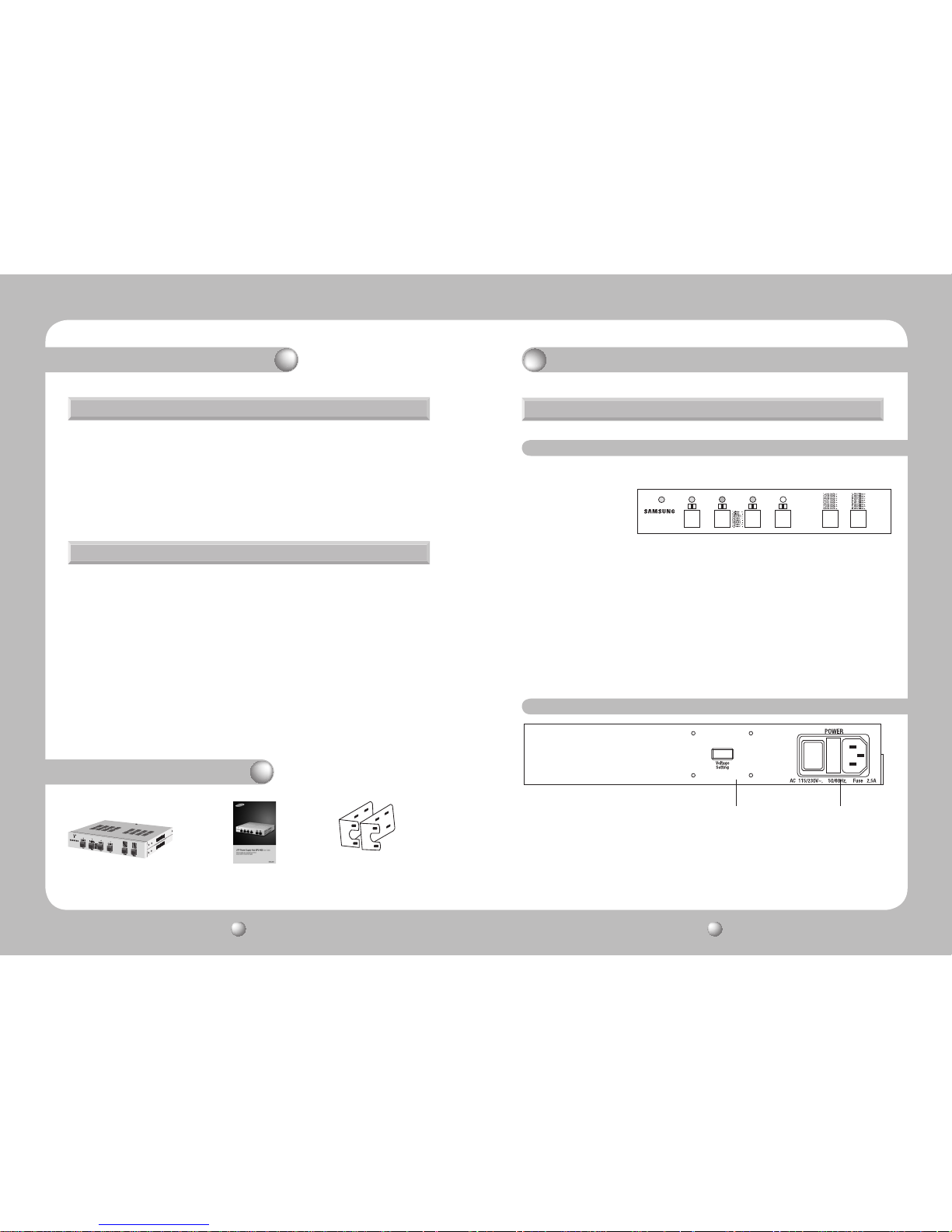
① AC Input Power Switch ② AC Inlet
- AC 115 V / AC 230 V
∙ Transfers power up to 400 m via CAT.5 UTP cable (Max. 1A)
∙ Equipped with an AC 24/28 V switch to adjust the power supply distance to the location of the
camera.
- 300m or Shorter : AC 24 V
- 300~400m : AC 28 V
∙ Automatically shuts down when the UTP cable becomes shorted out from a close distance
∙ UTP Cable Status LED
- OFF : No load
- Green : Normal
- Amber : Overload
- Red : Shorted
∙ RS-485 data port for controlling camera
∙ Lightning surge protection
1-1. Overview
3. Product Parts and Peripheral Device Connection
3-1. Part Names and Functions
3-1-1. Front
3-1-2. Back
1-2. Product Features
SPU-400
❶
SPU-400
2
User Guide
3
19” Rack Mount
① ②
① Power ON Status LED
② UTP Cable Status LED
- OFF : No load
- Green : Normal
- Amber : Overload
- Red : Shorted
③ AC 24/28 V Switch
- AC 24 V : For a 300 m or shorter UTP cable
- AC 28 V : For a 300 to 400 m UTP cable
※ The recommended distance is based on CAT.5 UTP cable. Depending on the type and
model of UTP cables and cameras, the power supply distance may vary.
④ Camera UTP Cable Terminal : Receives video signals and transfers power to a camera.
⑤ RS-485 Data Port
⑥ Receiver-Side : 4 video signal output ports
※ Recommended Cameras : The SUB-2000 and SUD-2080/2080F
POWER
CH1 CH2
CH3 CH4
DATA
VIDEO
AC
24V
AC
28V
AC
24V
AC
28V
AC
24V
AC
28V
AC
24V
AC
28V
SPU-400
 Loading...