

Samsung Spinpoint M9TU Product Manual

M9TU Product Manual
USB 3.0 - 2.5” Hard Disk Drive
September 05, 2013 Rev 1.0
PMM9T-USB3.0 100736109a

© 2013 Seagate Technology LLC. All rights reserved. Seagate and Seagate Technology are
registered trademarks of Seagate Technology LLC in the United States and/or other countries.
Momentus is either a trademark or registered trademark of Seagate Technology LLC or one of
its affiliated companies in the United States and/or other countries. All other trademarks or
registered trademarks are the property of their respective owners. When referring to drive
capacity, one gigabyte, or GB, equals one billion bytes and one terabyte, or TB, equals one
trillion bytes. Your computer’s operating system may use a different standard of
measurement and report a lower capacity. In addition, some of the listed capacity is used for
formatting and other functions, and thus will not be available for data storage. Actual data
rates may vary depending on operating environment and other factors. The export or reexport of hardware or software containing encryption may be regulated by the U.S.
Department of Commerce, Bureau of Industry and Security (for more information, visit
www.bis.doc.gov), and controlled for import and use outside of the U.S. Seagate reserves the
right to change, without notice, product offerings or specifications.

TABLE OF CONTENTS
CHAPTER 1 SCOPE ............................................................................................................................. 1
1.1 USER DEFINITION .............................................................................................................................. 1
1.2 M
ANUAL ORGANIZATION .................................................................................................................. 1
1.3 USB .................................................................................................................................................... 1
1.4 R
EFERENCE ........................................................................................................................................ 2
CHAPTER 2 DESCRIPTION ............................................................................................................. 3
2.1 INTRODUCTION .................................................................................................................................. 3
2.2 KEY FEATURES .................................................................................................................................. 3
2.3 S
TANDARDS AND REGULATIONS....................................................................................................... 4
2.4 H
ARDWARE REQUIREMENTS............................................................................................................. 4
CHAPTER 3 SPECIFICATIONS ....................................................................................................... 5
3.1 SPECIFICATION SUMMARY ................................................................................................................ 5
3.2 P
HYSICAL SPECIFICATIONS ............................................................................................................... 5
3.3 L
OGICAL CONFIGURATIONS.............................................................................................................. 5
3.4 PERFORMANCE SPECIFICATIONS ..................................................................................................... 6
3.5 P
OWER CONSUMPTION ..................................................................................................................... 7
3.6 E
NVIRONMENTAL SPECIFICATIONS ............................................................................................... 8
3.7 R
ELIABILITY SPECIFICATIONS ....................................................................................................... 9
CHAPTER 4 INSTALLATION......................................................................................................... 10
4.1 SPACE REQUIREMENTS................................................................................................................... 10
4.2 U
NPACKING INSTRUCTIONS............................................................................................................ 10
4.3 MOUNTING ...................................................................................................................................... 10
4.3.1 Orientation...................................................................................................................... 11
4.3.2 Ventilation ...................................................................................................................... 11
4.4 C
ABLE CONNECTORS....................................................................................................................... 12
4.4.1 USB Connectivity............................................................................................................ 12
4.5 D
RIVE INSTALLATION...................................................................................................................... 12
4.6 S
YSTEM STARTUP PROCEDURE ....................................................................................................... 13
CHAPTER 5 DISK DRIVE OPERATION........................................................................................ 14
5.1 HEAD / DISK ASSEMBLY (HDA) ...................................................................................................... 14
5.1.1 Base Casting Assembly ................................................................................................... 14
5.1.2 DC Spindle Motor Assembly ........................................................................................... 14
5.1.3 Disk Stack Assembly ....................................................................................................... 14
5.1.4 Head Stack Assembly ...................................................................................................... 14
5.1.5 Voice Coil Motor and Actuator Latch Assemblies ......................................................... 15
5.1.6 Air Filtration System....................................................................................................... 15
5.1.7 Load/Unload Mechanism................................................................................................ 16
5.2 D
RIVE ELECTRONICS ....................................................................................................................... 16
5.2.1 Digital Signal Process and Interface Controller ............................................................ 16
5.2.2 USB Interface Controller................................................................................................ 16
5.2.2.1 The Host Interface Control Block ................................................................................................. 16
5.2.2.2 The Buffer Control Block ............................................................................................................. 17
5.2.2.3 The Disk Control Block ................................................................................................................ 17
5.2.2.4 The Disk ECC Control Block........................................................................................................ 17
5.2.2.5 Power Management....................................................................................................................... 17
5.2.3 Read/Write IC ................................................................................................................. 18
5.2.3.1 Time Base Generator.......................................................................................................................... 18
5.2.3.2 Automatic Gain Control ..................................................................................................................... 18
5.2.3.3 Asymmetry Correction Circuitry (ASC) ............................................................................................ 18
5.2.3.4 Analog Anti-Aliasing Low Pass Filter ................................................................................................ 18
5.2.3.5 Analog to Digital Converter (ADC) and FIR ...................................................................................... 18
5.3 SERVO SYSTEM ................................................................................................................................ 20
5.4 R
EAD AND WRITE OPERATIONS ...................................................................................................... 20
5.4.1 The Read Channel........................................................................................................... 20
5.4.2 The Write Channel .......................................................................................................... 20

5.5 FIRMWARE FEATURES ..................................................................................................................... 21
5.5.1 Read Caching ................................................................................................................. 21
5.5.2 Write Caching ................................................................................................................. 22
5.5.3 Defect Management ........................................................................................................ 22
5.5.4 Automatic Defect Allocation ........................................................................................... 22
5.5.5 Multi Parities Error Correction ..................................................................................... 22
CHAPTER 6 USB INTERFACE AND USB COMMANDS ............................................................ 23
6.1 INTRODUCTION ................................................................................................................................ 23
6.2 PHYSICAL INTERFACE ..................................................................................................................... 23
6.2.1 Mechanical Interface ...................................................................................................... 23
6.2.1.1 Mechanical Overview ................................................................................................................... 23
6.2.1.2 Connector ...................................................................................................................................... 24
6.2.1.2.1 USB Connector Termination Data.... ........................................ ....................................................................... 24
6.2.1.2.2 Series “A” and Series “B” Receptacles ........................................................................................................ 25
6.2.1.2.3 Series “A” and Series “B” Plugs ................................................................................................................... 26
6.2.1.3 Cable................................................................................................................................................. 27
6.2.1.4 Cable Assembly.................................................................................................................................. 27
6.2.1.4.1 Standard Detachable Cable Assemblies .................................................................................................... 27
6.2.1.4.2 High-/full-speed Captive Cable Assemblies............................................................................................... 30
6.2.1.4.3 Low-speed Captive Cable Assemblies ........................................................................................................ 31
6.2.1.4.4 Prohibited Cable Assemblies ...................................................................................................................... 31
6.2.2 Electrical Interface .......................................................................................................... 32
6.2.2.1 Electrical Overview ............................................................................................................................ 32
6.2.2.2 Signaling ............................................................................................................................................ 33
6.2.2.3 High-speed (480Mb/s) Driver Characteristics ................................................................................... 34
6.2.2.4 High-speed (480Mb/s) Signaling Rise and Fall Times ...................................................................... 35
6.2.2.5 High-speed (480Mb/ s) Receiver Characteristics ............................................................................... 35
6.2.2.6 High-speed (480Mb/s) Signaling Levels ........................................................................................... 36
6.2.3 Power Distribution ......................................................................................................... 37
6.2.3.1 Overview .............................................................................................................................................. 37
6.2.3.2 Bus-powered Hubs ............................................................................................................................... 37
6.2.3.3 Self-powered Hubs .............................................................................................................................. 38
6.3 PROTOCOL LAYER ............................................................................................................................ 39
6.3.1 Protocol Layer Overview................................................................................................ 39
6.3.2 Common USB Packet Fields ........................................................................................... 40
6.3.2.1 SYNC Fields...................................................................................................................................... 40
6.3.2.2 Packet Identifier Fields...................................................................................................................... 40
6.3.2.3 Address Fields .................................................................................................................................. 41
6.3.2.4 Endpoint Fields.................................................................................................................................. 42
6.3.2.5 Frame Number Fi el ds ....................................................................................................................... 42
6.3.2.6 Data Fields ........................................................................................................................................ 42
6.3.2.7 Cyclic Redundancy Checks .............................................................................................................. 42
6.3.3 Packet Format ................................................................................................................. 43
6.3.3.1 Token Packet..................................................................................................................................... 43
6.3.3.2 Data Packet ....................................................................................................................................... 43
6.3.3.3 Handshake Packet ............................................................................................................................. 43
6.3.3.4 Start-of-Frame Packets................. ..................................................................................................... 44
6.3.4 Pipes ................................................................................................................................ 44
6.3.5 Transfer/Endpoint Types ................................................................................................. 45
6.3.5.1 Control Transaction........................................................................................................................... 46
6.3.5.2 Bulk Transaction................................................................................................................................ 48
6.3.6 USB Device Generic Framework .................................................................................... 50
6.3.6.1 USB Device Stat e ............................................................................................................................. 50
6.3.6.1.1 Attached .................................................................................................................................................. 51
6.3.6.1.2 Powered ................................................................................................................................................... 51
6.3.6.1.3 Default ..................................................................................................................................................... 52
6.3.6.1.4 Address ....................... .............................................................................................................................. 52
6.3.6.1.5 Configured ................................................................................................................................................ 52
6.3.6.1.6 Suspended ................................................................................................................................................ 52
6.3.6.1.7 Bus Enumeration ..................................................................................................................................... 52
6.3.6.2 Generic USB Device Operation...................................................................................................... 53
6.3.6.2.1 Dynamic Attachment and Removal ......................................................................................................... 53
6.3.6.2.2 Address Assignment ................................................................................................................................. 53
6.3.6.2.3 Configuration............................................................................................................................................ 54
6.3.6.2.4 Data Transfer ................... ........................................................................................................................ 54
6.3.6.2.5 Power Management .................................................................................................................................. 54
6.3.6.2.6 Request Processing ................................................................................................................................... 54

6.3.6.3 Standard USB Device Requests ..................................................................................................... 54
6.3.6.3.1 Standard USB Device Request Overview .............................................................................................. 56
6.3.6.3.2 Cl ea r Fea t u r e ( Request Code 1) ....... ..................................................................................................... 57
6.3.6.3.3 Get Configuration ( Request Code 8) ..................................................................................................... 58
6.3.6.3.4 Get Descriptor ( Request Code 6)........................................................................................................... 58
6.3.6.3.5 Get Interface ( Request Code 10) ........................................................................................................... 58
6.3.6.3.6 Get Status ( Request Code 0) .................................................................................................................. 59
6.3.6.3.7 Set Address ( Request Code 5) ................................................................................................................ 60
6.3.6.3.8 Set Configuration ( Request Code9) ....................................................................................................... 60
6.3.6.3.9 Set Descriptor ( Request Code 7)........................................................................................................... 62
6.3.6.3.10 Set Feature ( Request Code 3) ............................................................................................................... 62
6.3.6.3.11 Set Interface ( Request Code 11) ........................................................................................................... 63
6.3.6.3.12 Synch Frame ( Request Code 12) .......................................................................................................... 63
6.3.6.4 Standard USB Descriptor ............................................................................................................... 64
6.3.6.4.1 Standard USB Descriptor Overview .............................. ....................................................................... 64
6.3.6.4.2 D evi c e D es c r i pt o r ................................................................................................................................. 64
6.3.6.4.3 Device Qualifier Descriptor .................................................................................................................. 66
6.3.6.4.4 Configuration Descriptor ...................................................................................................................... 66
6.3.6.4.5 Other_Speed_Configuration_ Descriptor............................................................................................... 68
6.3.6.4.6 Interface Descriptor............................................................................................................................... 68
6.3.6.4.7 Endpoint Descriptor ....................... ....................................................................................................... 70
6.3.6.4.8 Stri ng Descriptor ................................................................................................................................... 72
6.4 BULK-ONLY TRANSPORT ................................................................................................................ 73
6.4.1 FUNCTIONAL CHARACTERISTICS .............................................................................................. 73
6.4.1.1 BULK-ONLY MASS STORAGE RESET (CLASS-SPECIFIC REQUEST).................................. 73
6.4.1.2 GET MAX LUN (CLASS-SPECIFIC REQUEST)........................................................................... 73
6.4.1.3 HOST/DEVICE PACKET TRANSFER ORDER............................................................................. 73
6.4.1.4 COMMAND QUEUING .................................................................................................. ................ 73
6.4.1.5 BI-DIRECTIONAL COMMAND PROTOCOL ............................................................................ 73
6.4.2 STANDARD DESCRIPTORS ........................................................................................................... 74
6.4.2.1 DEVICE DESCRIPTOR .................................................................................................................. 74
6.4.2.2 CONFIGURATIO N DESCRIPTOR (TABLE 6-22)........................................................................ 75
6.4.2.3 INTERFACE DESCRIPTOR ........................................................................................................... 75
6.4.2.4 ENDPOINT DESCRIPTOR .......................................................................................................... 76
6.4.3 PROTOCOL (COMMAND/DATA/STATUS) ................................................................................... 77
6.4.3.1 COMMAND BLOCK WRAPPER (CBW) ...................................................................................... 78
6.4.3.2 COMMAND STATUS WRAPPER (CSW) ..................................................................................... 79
6.4.3.3 DATA TRANSFER CONDITIONS ................................................................................................. 79
6.4.3.3.1 COMMAND TRANSPORT ...................................................... .............................................................. 79
6.4.3.3.2 DATA TRANSPORT......................................... ...................................................................................... 80
6.4.3.3.3 STATUS TRANSPORT .......................................................................................................................... 80
6.4.3.3.4 PHASE ERROR ...................................................................................................................................... 80
6.4.3.3.5 RESET RECOVERY………………………………………..................................................................... 80
6.4.4 HOST/DEVICE DATA TRANSFERS ............................................................................................... 80
6.4.4.1 OVERVIEW ..................................................................................................................................... 80
6.4.4.2 VALID AND MEANINGFUL CBW............................................................................................... 80
6.4.4.3 VALID AND MEANINGFUL CSW ............................................................................................... 81
6.4.4.4 DEVICE ERROR HANDLING ....................................................................................................... 81
6.4.4.5 HOST ERROR HANDLING ............................................................................................................ 81
6.4.4.6 ERROR CLASSES ........................................................................................................................... 81
6.4.4.6.1 CBW NOT VALID .................................................................................................................................. 81
6.4.4.6.2 INTERNAL DEVICE ERROR................................................................................................................. 81
6.4.4.6.3 HOST/DEVICE DISAGREEMENTS ..................................................................................................... 81
6.4.4.6.4 COMMAND FAILURE ........................................................................................................................... 81
6.5 UFI COMMAND SET ......................................................................................................................... 82
6.5.1 OVERVIEW ...................................................................................................................................... 82
6.5.1.1 HOST/UFI DEVICE CONCEPTUAL VIEW ............................................................................................... 82
6.5.1.2 UFI COMMAND SET OVERVIEW .................................................... ........................................................ 83
6.5.2 INQUIRY COMMAND (12H) .......................................................................................................... 84
6.5.3 READ(10) COMMAND (28H) ......................................................................................................... 85
6.5.4 READ CAPACITY COMMAND (25H) ............................................................................................ 85
6.5.5 READ FORMAT CAPACITY COMMAND (23H)............................................................................ 86
6.5.5.1 CAPACITY LIST ......................................................................................................................................... 87
6.5.6 WRITE(10) COMMAND (2AH) ................................................................................................... 88
CHAPTER 7 MAINTENANCE........................................................................................................ 89
7.1 GENERAL INFORMATION ............................................................................................................... 89
7.2 M
AINTENANCE PRECAUTIONS ......................................................................................................... 89
7.3 S
ERVICE AND REPAIR ...................................................................................................................... 91

TABLE OF TABLES
Table 3-1 : Specifications......................................................................................................................................... 5
Table 3-2 : Physical Specifications .......................................................................................................................... 5
Table 3-3 : Logical Configurations ........................................................................................................................... 5
Table 3-4 : Performance Specifications ..................................................................................................................... 6
Table 3-5 : Power consumption ................................................................................................................................ 7
Table 3-6 : Environmental Specifications ................................................................................................................. 8
Table 3-7 : Reliability Specifications ........................................................................................................................ 9
Table 4-1 : USB Connector Pin Definitions .............................................................................................................. 12
Table 4-2 : Logical Drive Parameters ....................................................................................................................... 13
Table 6-1 : USB Connector Termination Data .......................................................................................................... 24
Table 6-2 : High-speed Signaling Levels .................................................................................................................. 36
Table 6-3 : PID Types ............................................................................................................................................... 41
Table 6-4 : Visible Device States .............................................................................................................................. 51
Table 6-5 : Format of Setup Data .............................................................................................................................. 55
Table 6-6 : Standard Device Request ........................................................................................................................ 56
Table 6-7 : Standard Request Codes ......................................................................................................................... 57
Table 6-8 : Descriptor Types..................................................................................................................................... 57
Table 6-9 : Standard Feature Sectors ........................................................................................................................ 57
Table 6-10 : Test Mode Selectors ............................................................................................................................. 63
Table 6-11 : Standard Device Descriptor .................................................................................................................. 65
Table 6-12 : Device Qualifier Descriptor .................................................................................................................. 66
Table 6-13 : Standard Configuration Descriptor ....................................................................................................... 67
Table 6-14 : Other Speed Configuration Descriptor ................................................................................................. 68
Table 6-15 : Standard Interface Descriptor ............................................................................................................... 69
Table 6-16 : Standard Endpoint Descriptor ............................................................................................................... 70
Table 6-17 : Allowed wMaxPacketSize Values for Different Numbers of Transaction per Microframe................. 72
Table 6-18 : String Descriptor Zero, Specifying Language Supported by the Device .............................................. 72
Table 6-19 : UNICODE String Descriptor ................................................................................................................ 72
Table 6-20 : Bulk Only Transport Device Descriptor ............................................................................................... 74
Table 6-21 : Example Serial Number Format ........................................................................................................... 74
Table 6-22 : Bulk Only Transport Configuration Descriptor .................................................................................... 75
Table 6-23 : Bulk Only Data Interface Descriptor .................................................................................................... 75
Table 6-24 : Bulk-In Endpoint Descriptor................................................................................................................. 76
Table 6-25 : Bulk-Out Endpoint Descriptor .............................................................................................................. 76
Table 6-26 : Command Block Wrapper .................................................................................................................... 78
Table 6-27 : Command Status Wrapper .................................................................................................................... 79
Table 6-28 : Command Block Status Values ............................................................................................................ 79
Table 6-29 : UFI Commands Set ............................................................................................................................. 83
Table 6-30 : INQUIRY Command ............................................................................................................................ 84
Table 6-31 : INQUIRY Data Format ........................................................................................................................ 84
Table 6-32 : READ(10) Command ........................................................................................................................... 85
Table 6-33 : READ CAPACITY Command ............................................................................................................. 85
Table 6-34 : READ CAPACITY Data ...................................................................................................................... 86
Table 6-35 : READ FORMAT CAPACITY Command............................................................................................ 86
Table 6-36 : Capacity List......................................................................................................................................... 87
Table 6-37 : Capacity List Header ............................................................................................................................ 87
Table 6-38 : Current/Maximum Capacity Descriptor................................................................................................ 87
Table 6-39 : Descriptor Code Definition................................................................................................................. 88
Table 6-40 : Formattable Capacity Descriptor ........................................................................................................ 88
Table 6-41 : WRITE(10) Command ....................................................................................................................... 88

TABLE OF FIGURES
Figure 3-1 : Measurement Position ........................................................................................................................... 9
Figure 4-1 : Mechanical Dimension .......................................................................................................................... 10
Figure 4-2 : Mounting-Screw Clearance ................................................................................................................... 11
Figure 4-3 : USB connector type.............................................................................................................................. 12
Figure 5-1 : Exploded Mechanical View ................................................................................................................. 15
Figure 5-2 : Read/Write 88C10010........................................................................................................................... 19
Figure 6-1 : Interlayer Communication Flow............................................................................................................ 23
Figure 6-2 : Keyed Connector Protocol .................................................................................................................... 24
Figure 6-3 : USB Series “A” Receptacle Interface.................................................................................................... 25
Figure 6-4 : USB Series “B” Receptacle Interface .................................................................................................... 25
Figure 6-5 : USB Series “B” Plug Interface .............................................................................................................. 26
Figure 6-6 : USB Series “B” Plug Interface .............................................................................................................. 26
Figure 6-7 : USB Standard Detachable Cable Assembly .......................................................................................... 27
Figure 6-8 : USB High-/full-speed Hardwired Cable Assembly ............................................................................... 30
Figure 6-9 : USB Low-speed Hardwired Cable Assembly........................................................................................ 31
Figure 6-10 : USB Cable Signal................................................................................................................................ 32
Figure 6-11 : Example High-speed Capable Transceiver Circuit .............................................................................. 33
Figure 6-12 : Compound Bus-powered Hub ............................................................................................................ 38
Figure 6-13 : Compound Self-powered Hub ............................................................................................................. 38
Figure 6-14 : PID Format .......................................................................................................................................... 40
Figure 6-15 : ADDR Field ........................................................................................................................................ 41
Figure 6-16 : Endpoint Field ..................................................................................................................................... 42
Figure 6-17 : Data Field Format................................................................................................................................ 42
Figure 6-18 : Token Format ...................................................................................................................................... 43
Figure 6-19 : Data Packet Format ........................................................................................................................... 43
Figure 6-20 : Handshake Format ............................................................................................................................. 43
Figure 6-21 : SOF Packet ........................................................................................................................................ 44
Figure 6-22 : Control Transaction Model ................................................................................................................ 46
Figure 6-23 : Setup Stage ........................................................................................................................................ 46
Figure 6-24 : Data Stage ........................................................................................................................................... 47
Figure 6-25 : Status In Stage ................................................................................................................................... 47
Figure 6-26 : Status Out Stage ................................................................................................................................ 47
Figure 6-27 : Bulk Transaction Model .................................................................................................................... 48
Figure 6-28 : Bulk Transaction Diagram ................................................................................................................. 49
Figure 6-29 : Enumeration ...................................................................................................................................... 50
Figure 6-30 : Enumeration ...................................................................................................................................... 51
Figure 6-31 : wIndex Format when Specifying an Endpoint ................................................................................... 55
Figure 6-32 : wIndex Format when Specifying an Interface .................................................................................... 56
Figure 6-33 : Information Returned by a GetStatus() Request to a Device ............................................................ 59
Figure 6-34 : Information Returned by a GetStatus() Request to an Interface ......................................................... 59
Figure 6-35 : Information Returned by a GetStatus() Request to an Endpoint ......................................................... 60
Figure 6-36 : Command/Data/Status Flow .............................................................................................................. 77
Figure 6-37 : Status Transport Flow ........................................................................................................................ 77
Figure 6-38 : Host/UFI Device Conceptual View ..................................................................................................... 82
Figure 7-1 : HDD handling guide-Please handle HDD by side surfaces!..................................................................... 90
Figure 7-2 : HDD handling guide-Do not Touch Cover and PCB ............................................................................ 90
Figure 7-3 : HDD handling guide-Do Not Stack! ..……………………...................................................... 90
Figure 7-4 : HDD handling guide-Prevent Shocks! ................................................................................. 91

SCOPE
Spinpoint M9TU-USB 3.0 Product Manual REV 1.0
1
CHAPTER 1 SCOPE
Welcome to the Spinpoint™ M9TU USB 3.0 series of Samsung™ hard disk drive. This series of drives
consists of the following models: ST2000LM005 and ST1500LM008. This chapter provides an overview of the
contents of this manual, including the intended user, manual organization, terminology and conventions. In
addition, it provides a list of references that might be helpful to the reader.
1.1 User Definition
The Spinpoint M9TU-USB 3.0 product manual is intended for the following readers:
• Original Equipment Manufacturers (OEMs)
• Distributors
1.2 Manual Organization
This manual provides information about installation, principles of operation, and interface command
implementation. It is organized into the following chapters:
•
Chapter 1 - SCOPE
•
Chapter 2 - DESCRIPTION
•
Chapter 3 - SPECIFICATIONS
•
Chapter 4 - INSTALLATION
•
Chapter 5 - DISK DRIVE OPERATION
•
Chapter 6 - USB INTERFACE AND USB COMMANDS
•
Chapter 7 - MAINTENANCE
In addition, this manual contains a glossary of terms to help you understand important information
1.3 USB
A USB system has an asymmetric design, consisting of a host, a multitude of downstream USB ports, and
multiple peripheral devices connected in a tiered-star topology. Additional USB hubs may be included in
the tiers, allowing branching into a tree structure, subject to a limit of 5 levels of tiers. USB host may have
multiple host controllers and each host controller may provide one or more USB ports. Up to 127 devices,
including the hub devices may be connected to a single host controller.
USB supports four data rates:
A Low Speed (1.1, 2.0) rate of 1.5Mbit/s (187.5kB/s) that is mostly used for Human Interface Devices
(HID) such as keyboards, mice, and joysticks.
A Full Speed (1.1, 2.0) rate of 12Mbit/s (1.5MB/s). Full Speed was the fastest rate before the USB 2.0
specification and many devices fall back to Full Speed. Full Speed devices divide the USB bandwidth
between them in a first-come first-served basis and it is not uncommon to run out of bandwidth with
several isochronous devices. All USB Hubs support Full Speed.
A Hi-Speed (2.0) rate of 480Mbit/s (60MB/s).
A SuperSpeed (3.0) rate of 5Gbit/s (625MB/s)

SCOPE
Spinpoint M9TU-USB 3.0 Product Manual REV 1.0
2
1.4 Reference
For additional information about the USB interface, refer to:
• USB 0.7: Released in November 1994
• USB 0.8: Released in December 1994
• USB 0.9: Released in April 1995
• USB 0.99: Released in August 1995
• USB 1.0 Release candidate: Released in November 1995
• USB 1.0 (1.5Mbit/s, Low-Speed and 12Mbit/s, Full-Speed): Released in January 1996
• USB 1.1: Released in September 1998
• USB 2.0 (480Mbit/s, Hi-Speed): Released in April 2000
• USB 3.0 (5Gbit/s, SuperSpeed): Released in November 2008
For introduction about USB interface please refer to:
• Universal Serial Bus (USB*) Overview (URL: http://www.intel.com/technology/usb/index.htm)
• USB Implementers Forum, Inc (URL:
http://www.usb.org)
• USB 3.0 Specification (URL:
http://www.usb.org/developers/docs/)

Spinpoint M9TU-USB 3.0 Product Manual REV 1.0
3
DESCRIPTION
CHAPTER 2 DESCRIPTION
This chapter summarizes general functions and key features of the Spinpoint M9TU-USB 3.0 hard disk drive,
as well as the standards and regulations they meet.
2.1 Introduction
The Samsung Spinpoint M9TU-USB 3 .0 2.5 inch hard disk drive is high capacity, high performance random
access storage device, which uses non-removable 2.5-inch disks as storage media. Each disk incorporates thin film
metallic media technology for enhanced performance and reliability. And for each disk surface there is a
corresponding movable head actuator assembly to randomly access the data tracks and write or read the user data.
The Spinpoint M9TU-USB 3.0 hard disk drive includes the USB controller embedded in the disk drive PCB
electronics. The drive’s electrical interface is compatible with all mandatory, optional and vendor-specific
commands within the USB specification.
Drive size conforms to the industry standard 2.5-inch form factor and mini USB interface.
The Spinpoint M9TU-USB 3 .0 hard disk drive incorporates TuMR head and Noise Predictive PRML (Partial
Response Maximum Likelihood) signal processing technologies. These advanced technologies allow for areal
density of about 950 Gigabits per square inch and storage capacity of maximum 667 Gigabytes per disk.
The heads, disk(s), and actuator housing are environmentally sealed within an aluminum-alloy base and
cover. As the disks spin, air circulates within this base and cover, commonly referred to as the head and disk
assembly (HDA), through a non-replaceable absolute filter ensuring a contamination free environment for the
heads and disks throughout the life of the drive.
2.2 Key Features
Key features of the Spinpoint M9TU-USB 3.0 hard disk drive includes:
• Formatted capacities are 1.5TB and 2TB
• 9.5 ± 0.2 mm height form factor
• 5400 RPM Class
• 12 ms average seek time
• High accuracy rotary voice coil actuator with embedded sector servo
• Universal Serial Bus (USB) Interface (Supports USB 3.0 speed)
• Supports LBA Addressing modes
• Supports all logical geometries as programmed by the host
• 32MB buffer memory for read and write cache.
• Transparent media defect mapping
• High performance in-line defective sector skipping
• Auto-reassignment
• Automatic error correction and retries
• On-the-fly (OTF) error correction
• Noise predictive PRML read channel
• TA detection and correction
• TuMR/PMR head
• SMART III support
• 1MB = 1,000,000 Bytes, 1GB = 1,000,000,000 Bytes
Accessible capacity may vary as some OS uses binary numbering system for reported capacity

Spinpoint M9TU-USB 3.0 Product Manual REV 1.0
4
DESCRIPTION
2.3 Standards and Regulations
The Samsung Spinpoint M9TU / Seagate
®
Momentus® hard disk drive depends upon its host equipment to
provide power and appropriate environmental conditions to achieve optimum performance and compliance with
applicable industry and governmental regulations. Special attention has been given in the areas of safety,
power distribution, shielding, audible noise control, and temperature regulation.
The Spinpoint M9TU-USB 3.0 hard disk drive satisfies the following standards and regulations:
• Underwriters Laboratory (UL): Standard 1950.
Information technology equipment including business equipment.
• Canadian Standards Association (CSA): Standard C22.2 No.3000-201.
Information technology equipment including business equipment.
• Technisher Überwachungs Verein (TUV): Standard EN 60 950.
Information technology equipment including business equipment.
2.4 Hardware Requirements
The Spinpoint M9TU-USB 3.0 hard disk drive is designed for use with host computers and controllers
that are USB compatible. It is connected to a PC either by:
• Using an adapter board with USB interface, or
• Plugging a cable from the drive directly into a PC motherboard with an USB interface.

Spinpoint M9TU-USB 3.0 Product Manual REV 1.0
5
SPECIFICATIONS
CHAPTER 3 SPECIFICATIONS
This chapter gives a detail description of the physical, electrical and environmental characteristics of
the Spinpoint M9TU-USB 3.0 hard disk drive.
3.1 Specification Summary
Table 3-1: Specifications
DESCRIPTION
ST1500LM008 ST2000LM005
Number of R/W heads
6
6
Maximum BPI
2731K
Flexible data TPI
480K
Encoding method
LDPC (low density parity check) encoding
Interface
USB interface (Supports USB 3.0 speed)
Actuator type
Rotary Voice Coil
Servo type
Embedded Sector Servo
Spindle Speed (RPM)
5400 RPM Class
3.2 Physical Specifications
Table 3-2: Physical Specifications
DESCRIPTION ST1500LM008 ST2000LM005
Length (mm)
Width (mm)
Height (mm)
Weight (g, max)
103.9
69.85
9.5
130
3.3 Logical Configurations
Table 3-3: Logical Configurations
DESCRIPTION ST1500LM008 ST2000LM005
Total Number
of logical sectors
Capacity
2,930,277,168 3,907,029,168
1.5TB 2TB
* 1MB = 1,000,000 Bytes, 1GB = 1,000,000,000 Bytes
* Accessible capacity may vary as some OS uses binary numbering system for reported capacity.

Spinpoint M9TU-USB 3.0 Product Manual REV 1.0
6
SPECIFICATIONS
3.4 Performance Specifications
Table 3-4: Performance Specifications
DESCRIPTION ST1500LM008 ST2000LM005
Average Seek Time
12msec
Average Latency
5.6 ms
Spin up Time
6 sec
Data Transfer Rate (Max)
buffer to/from media
host to/from buffer
169 MB/s
625 MB/s
Rotational Speed
5,400 RPM Class
Buffer size
32MB
NOTES: ∗ Seek time is defined as the time from the receipt of a read, write or seek
command until the actuator has repositioned and settled on the desired track
with the drive operating at nominal DC input voltages and nominal operating
temperature.
∗ Average seek time is determined by averaging the time to complete 1,000
seeks of random length.
∗ Average latency is the time required for the drive to rotate 1/2 of a revolution
and on average is incurred after a seek completion prior to reading or writing
user data.
∗ Spin up time is the time elapsed between the supply voltages reaching operating
range and the drive being ready to accept all commands.
∗ Actual rotational speed can be different a little.

Spinpoint M9TU-USB 3.0 Product Manual REV 1.0
7
SPECIFICATIONS
3.5 Power consumption
Table 3-5: Power consumption
DESCRIPTION
ST1500LM008 ST2000LM005
Rated
Voltage V +5
Current A 0.85
Power Consumption
Spin-Up (Max) mA
750.00
Idle
Watt
1.8
Seq W/R (File) Watt
3.2
Random Seek Watt
3.0
Stand by
Watt
1.4
Sleep
Watt
1.4
Power Requirements
Tolerance For + 5V
%
+/- 5
Ripple, 0-30MHz
mV
p-p
100
Supply Rise Time
msec
7-100
Supply Fall Time
Sec
<5

Spinpoint M9TU-USB 3.0 Product Manual REV 1.0
8
SPECIFICATIONS
3.6 Environmental Specifications
Table 3-6: Environmental Specifications
DESCRIPTION
ST1500LM008 ST2000LM005
Ambient Temperature
Operating
Non-operating
Max. gradient
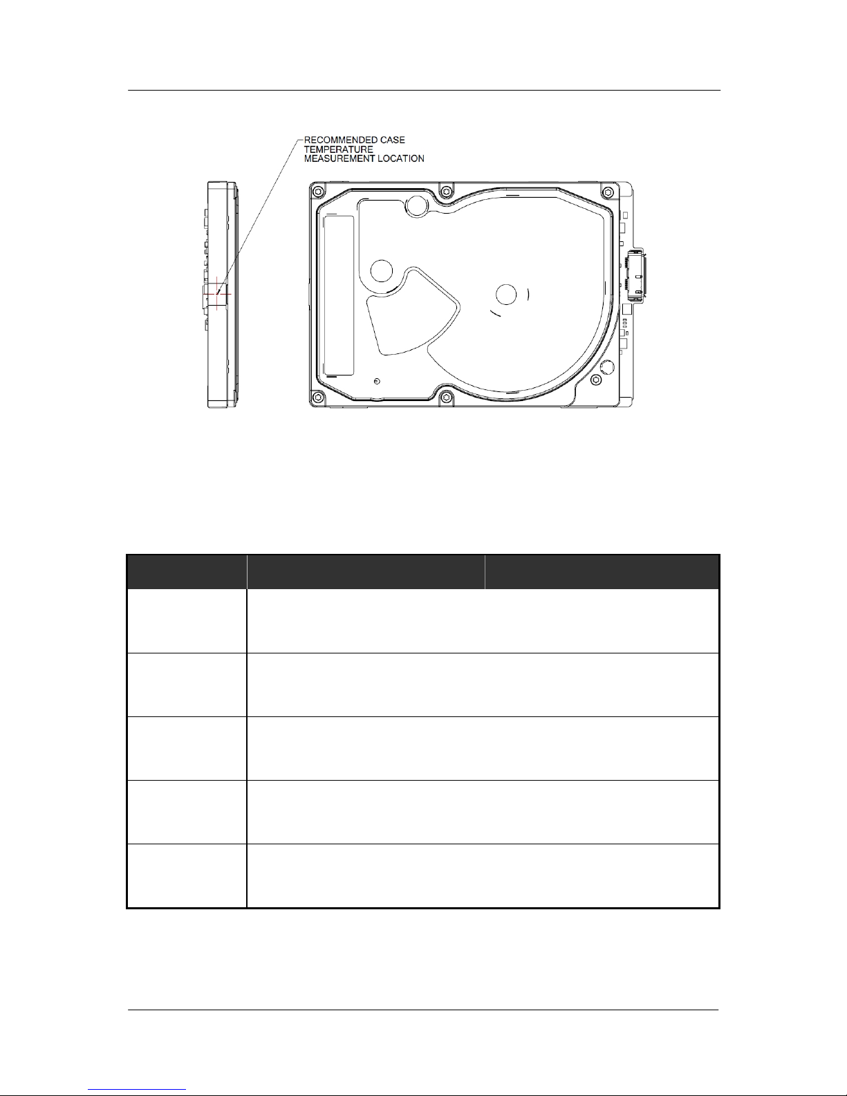
(Temperature/Humidity)
(Drive temperature measured on position of figure 3-1 should be max 65C
in range of 0°C -60°C, specified operation temperature.)
0 ∼ 60°C
-40 ∼ 70°C
20°C/20%/hr
Relative Humidity
(non condensing)
Operation
Non-operation
Maximum wet bulb
temperature
Operating
Non-operating
5~90 %
5~95 %
30° C
40° C
Altitude
(relative to sea level)
Operating
Non-operating
-304.8 ∼ 3,048 m
-304.8 ∼ 12,192 m
Vibration
Operating :
(10-500 Hz, Random)
Non-operating :
(10-500 Hz, Random)
1.5 Grms
5.85 Grms
mtLinear Shock
(1/2 sine pulse)
Operating 2.0 ms
Non-operating 1.0 ms
Rotational Shock
Operating 2.0 ms
Non-operating 2.0 ms
300G
800G
3K rad/sec
2
30K rad/sec
2
Acoustic Noise
(Typical Sound Power)
Idle
Seek
2.5 Bels
2.7 Bels
Spinpoint M9TU-USB 3.0 Product Manual REV 1.0
9
SPECIFICATIONS
Figure 3-1 :
Measurement Position.
3.7 Reliability Specifications
Table 3-7: Reliability Specifications
DESCRIPTION
ST1500LM008 ST2000LM005
Recoverable
Read Error
<10 in 10
11
bits
Non-Recoverable
Read Error
<1 sector in 10
14
bits
MTBF (POH)
550,000 hours
MTTR (Typical)
5 minutes
Load/Unload Cycles
Ambient
600,000
Spinpoint M9TU-USB 3.0 Product Manual REV 1.0
10
INSTALLATION
CHAPTER 4 INSTALLATION
This chapter describes how to unpack, mount, configure and connect a Spinpoint M9TU-USB 3.0
hard disk drive. It also describes how to install the drive in systems.
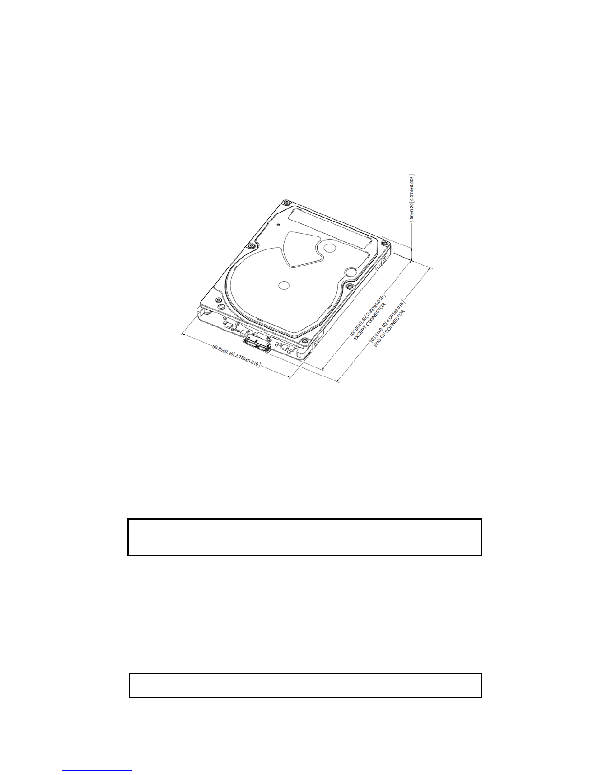
4.1 Space Requirements
Figure 4-1 shows the external dimensions of the drive.
Figure 4-1: Mechanical Dimension
4.2 Unpacking Instructions
(1) Open the shipping container of the Spinpoint M9TU-USB 3.0 hard disk drive.
(2) Lift the packing assembly that contains the drive out of the shipping container.
(3) Remove the drive from the packing assembly. When you are ready to install the drive, remove it from
the ESD (Electro Static Discharge) protection bag. Take precautions to protect the drive from ESD
damage after removing it from the bag.
CAUTION: During shipment and handling, the anti-static ESD protection bag prevents
electronic component damage due to electrostatic discharge. To avoid accidental damage to
the drive, do not use a sharp instrument to open the ESD protection bag.
(4) Save the packing material for possible future use.
4.3 Mounting
Refer to your system manual for complete mounting details.
(1) Be sure that the system power is off.
(2) For mounting, use four M3 screws.
CAUTION: Torque applied to the screws is recommended to be 3.5 [kg* cm] ±0.5
(3.0 [inch *pounds] ±0.5)
Spinpoint M9TU-USB 3.0 Product Manual REV 1.0
11
INSTALLATION
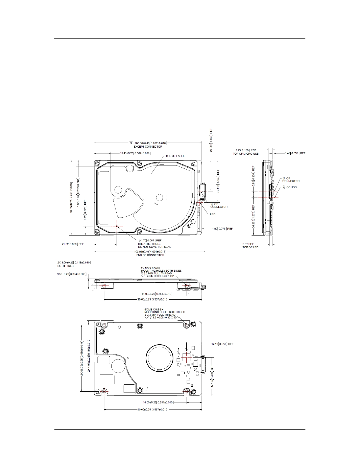
4.3.1 Orientation
Figure 4-2 shows the physical dimensions and mounting holes located on each side of the drive. The
mounting holes on Spinpoint M9TU-USB 3.0 hard disk drive allow the drive to be mounted in any direction.
4.3.2 Ventilation
The Spinpoint M9TU-USB 3.0 hard disk drive is designed to operate without the need of a cooling fan
provided the ambient air temperature does not exceed 60ºC. Any user-designed cabinet must provide
adequate air circulation to prevent exceeding the maximum temperature.
Figure4-2: Mounting Dimensions
Spinpoint M9TU-USB 3.0 Product Manual REV 1.0
12
INSTALLATION
4.4 Cable Connectors
4.4.1 USB Connectivity
The USB interface is connected within a point to point
configuration with the USB host port. There is no master
or slave relationship within the devices. Spinpoint
M9TU-USB 3.0 does not require extra power.
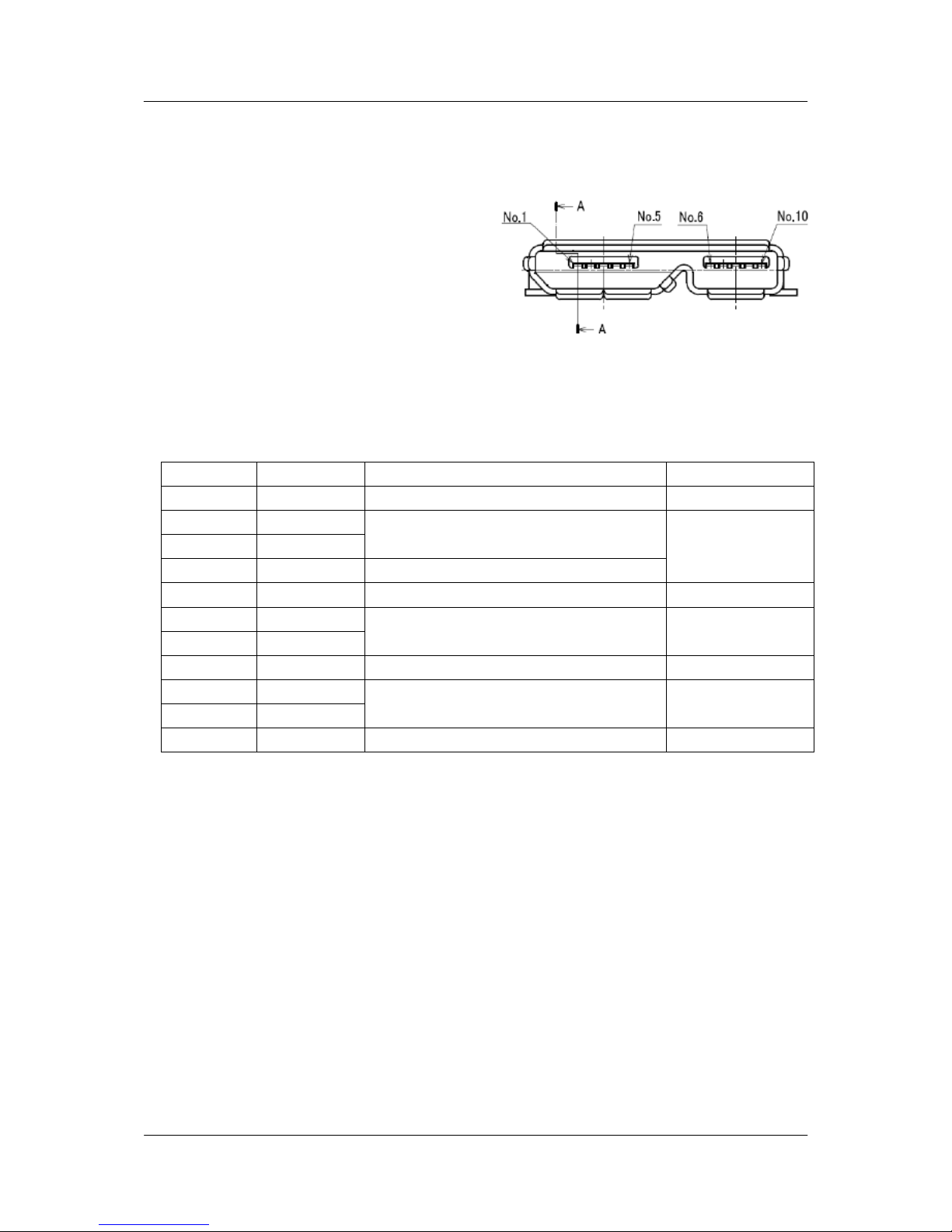
USB3.0 Micro B type applied to Spinpoint M9TU-USB
3.0. Figure 4.3 illustrates USB3.0 Micro B type
connector.
Figure 4-3 USB connector type
Table 4-1 lists the signals connection on the USB interface.
Table 4-1 USB Connector Pin
Definitions
Pin Number Signal Name Description Mating Sequence
1 VBUS Power Second
2 D-
USB 2.0 differential pair
Last
3 D+
4 ID OTG identification
5 GND Ground for power return Second
6 MicB_SSTX-
SuperSpeed transmitter differential pair
Last
7 MicB_SSTX+
8 GND_DRAIN Ground for SuperSpeed signal return Second
9 MicB_SSRX-
SuperSpeed receiver differential pair
Last
10 MicB_SSRX+
Shell Shield Connector metal shell First
4.5 Drive Installation
The Spinpoint M9TU-USB 3.0 hard disk drive can be installed in an USB-compatible system:
• To install the drive with a motherboard that contains USB port, connect the drive to the USB port using a
USB plugs (Micro B type).
• If the drive connects to the USB Hub or Keyboard USB port, make the drive bad detection or bad
operation (because of low bus power).
• If some OS in PC System or Host cannot detection the drive, the system need USB driver installation.

Spinpoint M9TU-USB 3.0 Product Manual REV 1.0
13
INSTALLATION
4.6 System Startup Procedure
Once the Spinpoint M9TU-USB 3.0 hard disk drive and along with the adapter board (if
required) have been installed in your system, the drive can now be partitioned and formatted
for operation. To set up the drive correctly, follow these instructions:
1. Power on the system.
2. Typically the system will detect a configuration change automatically. If so, then jump to step 5.
3. Connected Drive Detection normally as removable disk but cannot access drive folder, please create
partition & format first.
4. Perform the following steps that applies to your system: (example for XP)
I. Select Control Panel - Computer Management - Disk Manager in OS Utility.
II. Click the right mouse button of Selected USB device disk, and select New Partition.
III. Step 1. Click Next Button.
IV. Step 2. Select Partition Type and Click Next Button.
V. Step3. Select Partition Size and Click Next Button
VI. Step 4. Assign Drive Letter and Click Next Button.
VII. Step 5. Select File System, quick format option and Click Next Button.
VIII. Step 6. Click Finish Button
5. If the system recognizes the drive but experiences problem on properly handling the full capacity of the
drive, run Disk Manager utility program provided by Seagate and follow the instructions. The Disk
Manager utility program is available from Seagate on a floppy diskette, or downloadable from the Seagate
website at
http://www.seagate.com. If, after all these steps are successfully completed, your system will not
boot up, then contact technical support.
Table 4-2: Logical Drive Parameters
DESCRIPTION
ST1500LM008 ST2000LM005
Total Number of
logical sectors
Capacity
2,930,277,168 3,907,029,168
1.5TB 2TB
NOTES:
• The total numbers of sectors is calculated by (Cylinders x Heads x Sectors) of the selected drive
type.
• 1MB = 1,000,000 Bytes, 1GB = 1,000,000,000 Bytes
Accessible capacity may vary as some OS uses binary numbering system for reported capacity.
• Windows 95 or 98 that use FAT16 file system will limit the drive’s logical partition at 2.1GB
per logical drive. Windows95 OSR2 or later allow for the FAT32 file system which provides
access to greater than 2GB of logical capacity.
• A low-level format is not required, as this was done at the factory before shipment.

Spinpoint M9TU-USB 3.0 Product Manual REV 1.0
14
INSTALLATION
CHAPTER 5 DISK DRIVE OPERATION
This chapter describes the operation of the Spinpoint M9TU-USB 3.0 hard disk drive functional subsystems.
It is intended as a guide to the operation of the drive, rather than a detailed theory of operation.
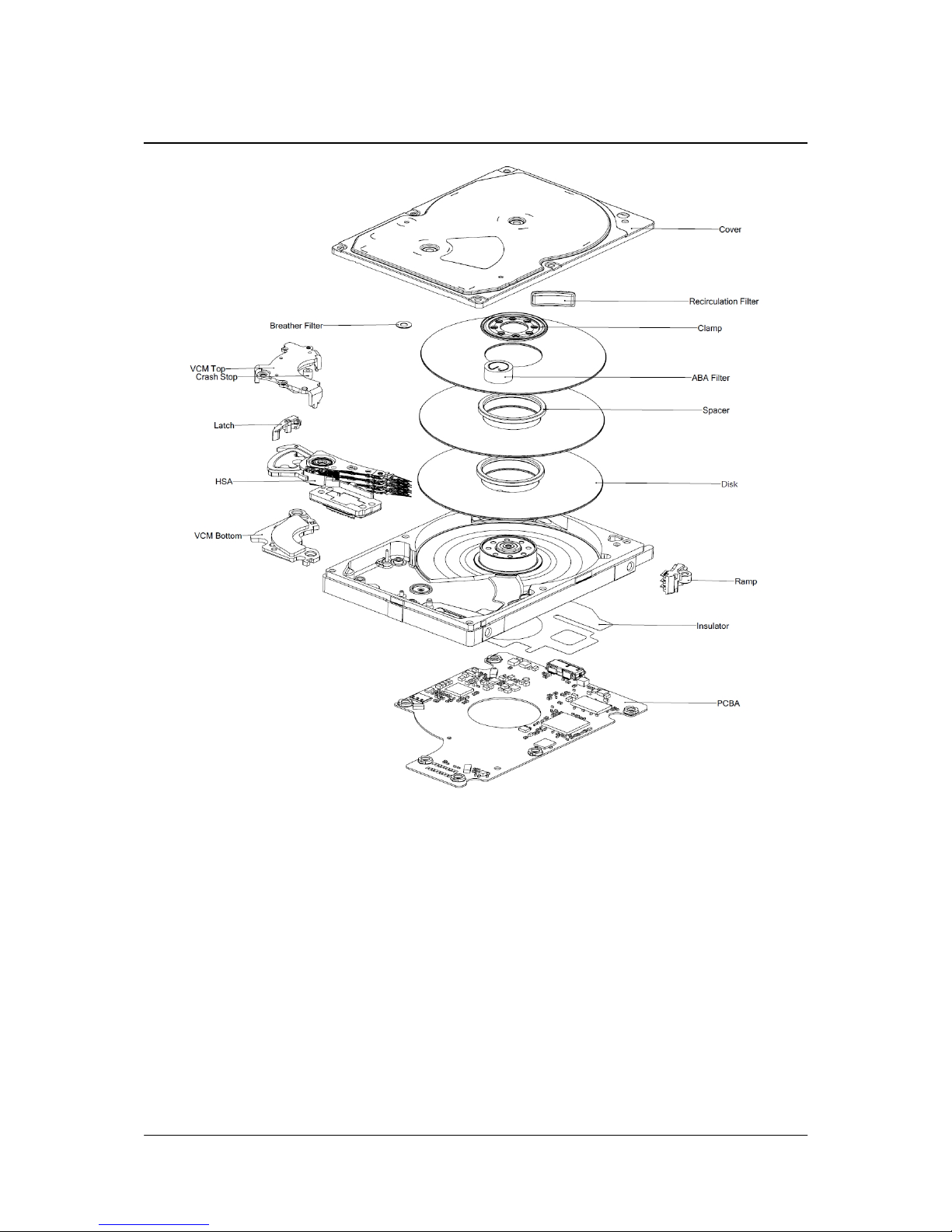
5.1 Head / Disk Assembly (HDA)
The Spinpoint M9TU-USB 3.0 hard disk drive consists of a mechanical sub-assembly and a printed circuit
board assembly (PCBA), as shown in Figure 5-1. This section describes the mechanism of the drive.
The head / disk assembly (HDA) contains the mechanical sub-assemblies of the drive, which are sealed
between the aluminum-alloy base and cover. The HDA consists of the base casting assembly (which
includes the DC spindle motor assembly), the disk stack assembly, the head
stack assembly, and the rotary
voice coil motor assembly (which includes the actuator latch assembly). The HDA is assembled in a clean
room. These subassemblies cannot be adjusted or field repaired.
CAUTION: To avoid contamination in the HDA, never remove or adjust its cover
and seals. Disassembling the HDA voids your warranty.
The Spinpoint M9TU-USB 3.0 hard disk drive models and capacities are distinguished by the number of
heads and disks. The ST750LM023 have three (3) disks and six (6) read/write heads. The ST1000LM025 has
two (2) disks and four (4) read/write heads.
5.1.1 Base Casting Assembly
A one piece, aluminum-alloy base casting provides a mounting surface for the drive mechanism and PCBA.
The base casting also serves as the flange for the DC spindle motor assembly. A gasket provides a seal
between the base and cover that enclose the drive mechanism.
5.1.2 DC Spindle Motor Assembly
The DC spindle motor assembly consists of the brush-less three-phase motor, spindle bearing (FDB)
assembly, disk mounting hub, and a labyrinth seal. The entire spindle motor assembly is completely
enclosed in the HDA and integrated to the base casting. The labyrinth seal prevents bearing lubricant from
coming out into the HDA.
5.1.3 Disk Stack Assembly
The disk stack assembly in the Spinpoint M9TU-USB 3.0 hard disk drive consists of 3 disks and disk spacers
secured on the hub of the spindle motor assembly by a disk clamp. The glass disks have a sputtered thin-film
magnetic co at
ing.
5.1.4 Head Stack Assembly
The head stack assembly consists of an E-block/coil sub-assembly, read/write heads, a flexible circuit, and
bearings. The E-block/coil sub-assembly is assembled with an E-block and bonded coil. Read/write heads
are mounted to spring-stainless steel flexures that are then swage mounted onto the E-block arms.
The flexible circuit connects the read/write heads with the PCBA via a connector through the base casting.
The flexible circuit contains a read/write Preamplifier IC.
Spinpoint M9TU-USB 3.0 Product Manual REV 1.0
15
INSTALLATION
Figure 5-1: Exploded Mechanical View
5.1.5 Voice Coil Motor and Actuator Latch Assemblies
The rotary voice coil motor consists of upper and lower permanent magnets and magnetic yokes fixed to the
base casting and a rotary bonded coil on the head stack assembly. Each magnet consists of two alternating
poles and is attached to the magnet yoke. Pawl latch and rubber crash stops mounted on a magnetic yoke
physically p revent the head(s) from moving beyond the designed inner boundary into the spindle or off the
disk surface.
Current from the power amplifier induces a magnetic field in the voice coil. Fluctuations in the field around
the permanent magnets move the voice coil s
o that heads can be positioned in the requested cylinder.
5.1.6 Air Filtration System
Heads fly very close to the disk surfaces. Therefore, it is very important that air circulating within the drive be
maintained free of particles. Seagate HDAs are assembled in a purified air environment to ensure cleanliness
and then sealed with a gasket. To retain this clean air environment, the Spinpoint M9TU-USB 3.0 hard disk
drive is equipped with a re-circulating filter, which is located in the path of the airflow close to the rotating
disk and is designed to trap any particles that may develop inside HDA.

DISK DRIVE OPERATION
Spinpoint M9TU-USB 3.0 Product Manual REV 1.0
16
5.1.7 Load/Unload Mechanism
Portable computer is exposed to heavy handling environment comparing with desk top computer. Load/Unload
mechanism provides to protect data loss caused by head hitting to disk due to the abnormal shock and vibration in
the transportation and handling.
When power is shut down, head will move to parking position on the ramp.
5.2 Drive Electronics
The Spinpoint M9TU-USB 3.0 hard disk drive attains its intelligence and performance through the
specialized electronic components mounted on the PCBA. The components are mounted on one side of the
PCBA.
The Preamplifier IC is the only electrical component that is not on the PCBA. It is mounted on the flexible
circuit inside the HDA. Locating the Preamplifier IC as close as possible to the read/write heads via surface
mount technology improves the signal to noise ratio.
5.2.1 Digital Signal Process and Interface Controller
The DSP core controller has a dual ARM CPU that incorporates a true 16-bit digital signal processor (DSP),
a bus controller unit (BCU), an interrupt controller unit (ICU), a general purpose timer (GPT), and SRAM
5.2.2 USB Interface Controller
The USB interface disk controller works in conjunction with the DSP core to perform the USB interface
control, buffer data flow management, disk format/read/write control, and error correction functions of an
embedded disk drive controller. The DSP communicates with the disk controller module by reading from
and writing to its various internal registers.
To the DSP core, the registers of the disk controller appear as unique memory or I/O locations that are
randomly accessed and operated upon. By reading from and writing to the registers, the DSP core initiates
operations and examines the status of the different functional blocks. Once an operation is started, successful
completion or an error condition may cause the disk controller to interrupt the DSP core, which then
examines the status registers of the disk controller and determines an appropriate course of action. The local
DSP core may also poll the device to ascertain successful completion or error conditions.
5.2.2.1 The Host Interface Control Block
The HBI module responds to the command issued from the host and controls the data transfer between the
buffer memory module and the host.
The HBI module supports the following main features:
• Power Saving
• 8/16 bit host interface
• A deep FIFO (32 x 32 bit) used as the temporary buffer for the data transfer
• 512 byte
• Microprocessor Interrupts
• 6 endpoints ( EP0-EP2 IN/OUT)
• Mass Storage class bulk-only transport with flow control
• Support Control transport
• Support Suspend/resume mode

DISK DRIVE OPERATION
Spinpoint M9TU-USB 3.0 Product Manual REV 1.0
17
5.2.2.2 The Buffer Control Block
The Buffer Control block manages the flow of data into and out of the buffer. Significant automation
allows buffer activity to take place automatically during read/write operations between the host and the disk.
This automation works together with automation within the Host Interface Control and Disk Control blocks to
provide more bandwidth for the local microprocessor to perform non-data flow functions.
The buffer control circuitry keeps track of buffer full and empty conditions and automatically works with the
Disk Control block to stop transfers to or from the disk when necessary. In addition, transfers to or from the
host are automatically stopped or started based on buffer full or empty status.
Additional functionality is provided in the Buffer Control block through the following features:
• Increased automation to support minimal latency read operations with minimal latency.
• Capability to support the execution of multiple consecutive Auto-Write commands without loss of data
due to overwriting of data.
• Auto write pointer.
• A disk sector counter that can monitor the transfers between the disk and buffer.
• Read/Write cache support.
5.2.2.3 The Disk Control Block
The Disk Control block manages the flow of data between the disk and the buffer. Many flexible features and
elements of automation have been incorporated to complement the automation contributed by the Host and Buffer
blocks.
The Disk Control block consists of the programmable sequencer (Disk Sequencer), CDR/data split logic, disk
FIFO, fault tolerant sync detect logic, and other support logic.
The programmable sequencer contains a 32-by-4 byte programmable SRAM and associated control logic, which
is programmed by the user to automatically control all single track format, read, and write operations. From within
the sequencer micro program, the Disk Control block can automatically deal with such real time functions as
defect skipping, servo burst data splitting, branching on critical buffer status and data compare operations. Once
the Disk Sequencer is started, it executes each word in logical order. At the completion of the current instruction
word, it either continues to the next instruction, continues to execute some other instruction based upon an internal
or external condition having been met, or it stops.
During instruction execution or while stopped, registers can be accessed by the DSP to obtain status
information reflecting the Disk Sequencer operations taking place.
5.2.2.4 The Disk ECC Control Block
The Disk Control Block supports a programmable LDPC code. Error detection and correction is handled in
the Disk Control block. Automatic on-the-fly hardware correction will take place. Correction is guaranteed to
complete before the parity bits of the sector following the sector where the error occurred utilizing standard
ATA size sectors.
5.2.2.5 Power Management
Power managemen t features are incorp orated into each block of the Spinpoint M9TU-USB 3.0. This allows
the designer to tailor the amount of power management to the specified design. Other power management
features include:
• Independent power management control for each block.
• DSP block powered down and up when needed.
• Disk Sequencer and associated disk logic powered up when the Disk Sequencer is started.
• Weak pull-up structure on input pins to prevent undesirable power consumption due to floating CMOS
inputs.

Spinpoint M9TU-USB 3.0 Product Manual REV 1.0
18
DISK DRIVE OPERATION
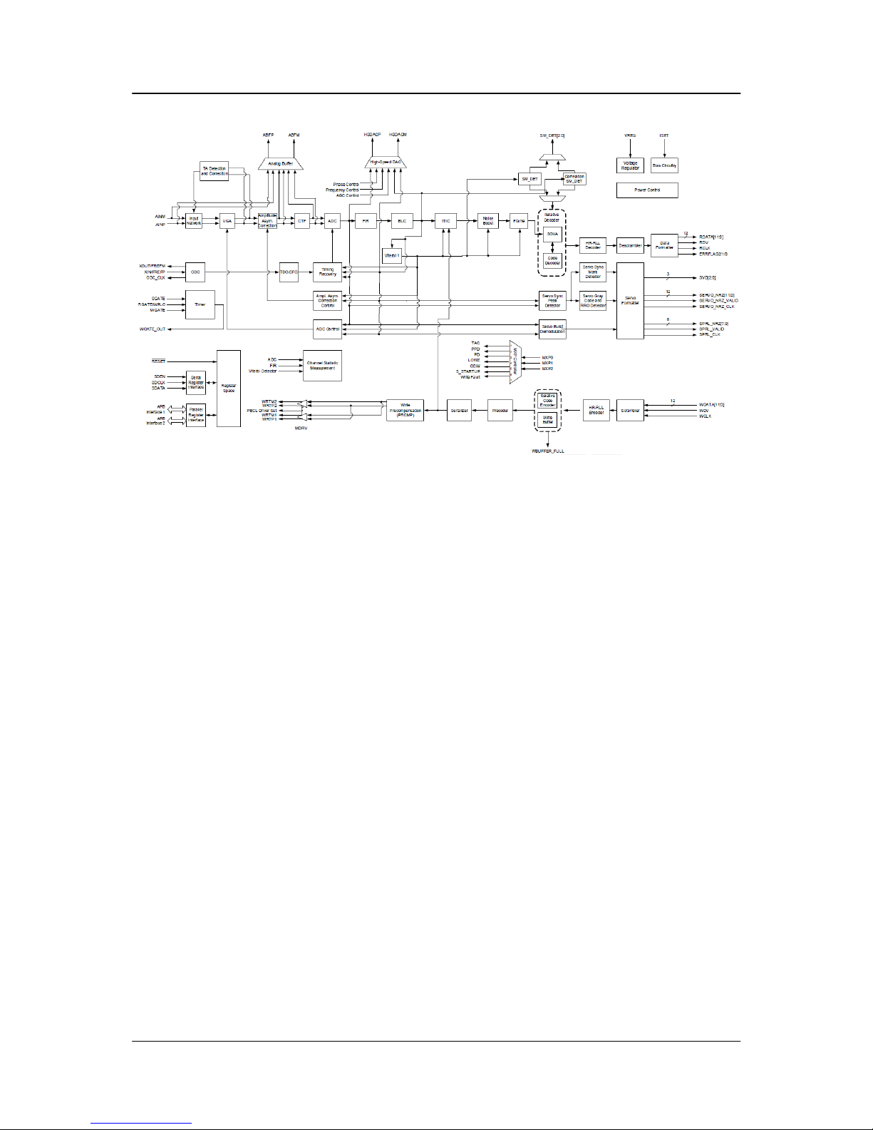
5.2.3 Read/Write IC
The Read/Write IC, shown in Figure 5-2 provides read/write-processing functions for the drive. The
Read/Write IC receives the Read GATE and Write GATE signals, write data, and servo AGC and gates from
the Interface Controller. The Read/Write IC sends decoded read data and the read reference clock. It
receives write data from the Interface Controller.
The 88C10010 which is embedded in 88i1022 is a sampled-data digital PRML channel designed to work
with a disk controller and a read/write preamplifier to provide the signal processing elements required to build
a state of the art high density, high speed disk d rive. The 88C10010 implements a noise predictive, PRML
Viterbi read channel (supporting) zone-bit recording,
The read/write channel functions include a time base generator, AGC circuitry, asymmetry correction
circuitry (ASC), analog anti-aliasing low-pass filter, analog to digital converter (ADC), digital FIR filter,
timing recovery circuits, Viterbi detector, sync mark detection, 30/32 rate block code ENDEC, serializer and
de-serializer, and write pre-compensation circuits. Servo functions include servo data detection and PES
demodulation. Additionally the 88C10010 contains specialized circuitry to perform various parametric
measurements on the processed read signal. This allows for implementation of self-tuning and optimization
capability in every drive
built using the 88C10010.
A 12-bit NRZ interface is provided to support high speed data transfers and from the controller.
Programming of the 88C10010 is performed through a serial interface. The serial interface is also used to
read various channel parameters that are computed on the fly.
5.2.3.1 Time Base Generator
The time base generator provides the write frequency and serves as a reference clock to the synchronizer during
non-read mode.
5.2.3.2 Automatic Gain Control
The AGC accepts a differential signal from the pre-amp, and provide constant output amplitude to the analog
filter. It’s capable of accepting signal ranges from 50 mV to 400 mVppd.
5.2.3.3 Asymmetry Correction Circuitry (ASC)
The ASC circuit is designed to correct for amplitude asymmetry introduced by MR heads . The compensation
range of this circuit is +/-30%. This circuit allows optimal bias current to be used independent of the
asymmetry effect.
5.2.3.4 Analog Anti-Aliasing Low Pass Filter
The 5
th
order equal-ripple analog filter provides filtering of the analog signal from AGC before it’s being
converted to digital signal with the ADC. Its main function is to avoid aliasing for the ADC circuit.
5.2.3.5 Analog to Digital Converter (ADC) and FIR
The output of the analog filter is quantified using a 6 bit FLASH ADC. The digitized data is then equalized by
the FIR to the NPV target response for Viterbi detection. The FIR filter consists of 10 independent
programmable taps
Spinpoint M9TU-USB 3.0 Product Manual REV 1.0
19
DISK DRIVE OPERATION
Figure 5-2: Read/Write 88C10010

Spinpoint M9TU-USB 3.0 Product Manual REV 1.0
20
DISK DRIVE OPERATION
5.3 Servo System
The Servo System controls the position of the read/write heads and holds them on track during read/write
operations. The Servo System also compensates for MR write/read offsets and thermal offsets between
heads on different surfaces and for vibration and shock applied to the drive.
The Spinpoint M9TU-USB 3.0 hard disk drive is an Embedded Sector Servo System. Positioning
information is radically located in evenly spaced servo sectors on each track.
Radial position information can be provided from these sectors for each data head. Because the drive
incorporates multiple data zones and each zone has a different bit density, split data fields are necessary for
optimal use of the non-servo area of the disk. The servo area remains phase-coherent across the surface of
the disk, even though the disk has various data zones. The main advantage of the Embedded Sector Servo
System is that it eliminates the problems of static and dynamic offsets between heads on different surfaces.
The Spinpoint M9TU-USB 3.0 hard disk drive Servo System is classified as a digital se
rvo system because
track-following and seek control, bias cancellation, and other typical tasks are done in a Digital Signal Processor
(DSP).
The Servo system has three modes of operation: track-following mode, settle mode, and velocity control
mode.
1. Track-following mode is used when heads are “on-track.” This is a position loop with an
integrator in the compensation.
2. Settle mode is used for all accesses; head switches, short-track seeks and long-track seeks.
Settle mode is a position loop with velocity damping. Settle mode does not use feed forward.
3. Velocity control mode is used for acceleration and deceleration of the actuator for seeking of
two or more tracks. A seek operation of this length is accomplished with a velocity control
loop. The drive’s ROM stores the velocity profile in a look-up table.
5.4 Read and Write Operations
The following two sections describe the read and write channels.
5.4.1 The Read Channel
The drive has one read/write head for each of the data surfaces. The signal path for the Read Channel starts at the
read/write heads. When the magnetic flux transitions recorded on a disk pass under the head, they generate lowamplitude, differential output voltages. The read/write head transfers these signals to the flexible circuit’s amplifier,
which amplifies the signal .
The flexible circuit transmits the pre-amplified signal from the HDA to the PCBA. The EPRML channel on the
PCBA shap es, filters, detects, synchronizes, and decodes the data from the disk. The Read/Write IC then sends the
resynchro ni z ed data output to t he 88i1022 DSP & Inte rface/Disk Controller.
The 88i1022 Disk Controller manages the flow of data between the Data Synchronize r on the Read/Write IC an d i ts
AT Interface Controller. It also controls data access for the external RAM buffer. The ENDEC of 88C10010
decodes the LDPC with post-processor format to produce a serial bit stream. This NRZ (Non Return to Zero) serial
data is converted to 12-bits.
The Sequencer module iden tifies the data as belonging to the target sector . A fter a full sector is r ea d , t he
88i1022 checks to see if the firmware ne eds to apply an ECC algorithm to the data . The Buffer Control section of
the 88i1022 stores the data in the cache and transmits the data to the AT bus.

Spinpoint M9TU-USB 3.0 Product Manual REV 1.0
21
DISK DRIVE OPERATION
5.4.2 The Write Channel
The signal path for the Write Channel follows the reverse order of that for the Read Channel. The host transmits
data via the AT bus to the 88i1022 Interface Controller. The Buffer Controller section of the 88i1022 stores the data
in the cache. Because the data is transmitted to the drive at a rate that exceeds the rate at which the drive can write
data to the disk, data is stored temporarily in the cache. Thus, the host can present data to the drive at a rate
independe nt of the rate at which the drive c a n wr ite da ta t o th e dis k .
Upon correct identification of the target address, the data is shifted to the Sequencer, which generates and appends
an error correcting code. The Sequencer then converts the bytes of data to a serial bit stream. The AT controller also
generates a preamble field, inserts an address mark, and transmits the data to the ENDEC in the R/W IC where the
data is encoded into the LDPC format and pre-compensates for non-linear transition shift. The amount of write
current is set by the 88i1022 DSP and Interface/Disk Controller through t he serial interface to the preamplifier .
The 88i1022 switches the Preamplifier and Write Driver IC to write mode and selects a head. Once the Preamplifier
and Write Driver IC receives a write gate signal, it transmits current reversals to the head, which writes magnetic
transitions on the disk.
5.5 Firmware Features
This section describes the following firmware features:
• Read Caching
• Write Caching
• Track Skewing
• Defect Management
• Automatic Defect Allocation
• ECC Correction
5.5.1 Read Caching
The Spinpoint M8U-USB 3.0 hard disk drive uses a 32MB Read Cache to enhance drive performance and
significantly improve system throughput. Use the SET FEATURES command to enable or disable
Read Caching. Read caching anticipates host-system requests for data and stores that data for faster future
access. When the host requests a certain segment of data, the cache feature utilizes a prefetch strategy to
get the data in advance and automatically read and store the following data from the disk into fast RAM.
If the host requests this data, the RAM is accessed rather than the disk.
There is a high probability that subsequent data requested will be in the cache, because more than 50 percent
of all disk requests are sequential. It takes microseconds rather than milliseconds to retrieve this cached
data. Thus Read Caching can provide substantial time savings during at least half of all disk requests. For
example, Read Caching could save most of the disk transaction time by eliminating the seek and rotational
latency delays that prominently dominate the typical disk transaction.
Read Caching operates by continuing to fill its cache memory with adjacent data after transferring data
requested by the host. Unlike a non-caching controller, the 88i1022 Interface Controller continues a read
operation after the requested data has been transferred to the host system. This read operation terminates
after a programmed amount of subsequent data has been read into the cache memory.
The cache memory consists of a 32MB sync DRAM buffer allocated to hold the data. It can be directly
accessed by the host by means of read and write commands. The unit of data stored is the logical block, or a
multiple of the 512-byte sector. Therefore, all accesses to cache memory must be in multiples of the sector
size. The following commands empty the cache:
• IDENTIFY DRIVE (ECh)
• FORMAT TRACK (50h)
• EXECUTE DRIVE DIAGNOSTIC (90h)
• READ LONG (23h)
• WRITE VERIFY (3Ch)

Spinpoint M9TU-USB 3.0 Product Manual REV 1.0
22
DISK DRIVE OPERATION
• INITIALIZE DEVICE PARAMETER (91h)
• SLEEP (99h, E6h)
• STANDBY IMMEDIATELY (94h, E0h)
• READ BUFFER (E4h)
• WRITE BUFFER (E8h)
• WRITE SAME (E9h)
5.5.2 Write Caching
Write caching improves both single and multi-sector write performance by reducing delays introduced by
rotational latency. When the drive writes a pattern of multiple sequential data, it stores the data to a cache
buffer and immediately sends a COMMAND COMPLETE message to the host before it writes the data to the
disk.
The data is then written collectively to the drive thereby minimizing the disk seeking operation. Data is
held in cache no longer than the maximum seek time plus rotational latency. Host retries must be enabled
for Write Caching to be active.
If the data request is random, the data of the previous command is written to the disk before COMMAND
COMPLETE is posted for the current command. Read commands work similarly. The previous write is
allowed to finish before the read operation starts.
If a defective sector is found during a write, the sector is automatically relocated before the write occurs.
This ensures that cached data that already has been reported as written successfully gets written, even if an
error should occur.
If the sector is not automatically relocated, the drive drops out of write caching and reports the error as an ID
Not Found. If the write command is still active on the AT interface, the error is reported during that
command. Otherwise, it is reported on the next command.
5.5.3 Defect Management
The Spinpoint M9TU-USB 3.0 hard disk drive media is scanned for defects. After defect scanning, the
defective sectors are saved in the defect list. A defect encountered in the manufacturing process is slipped to
the next physical sector location. All logical sector numbers are pushed down to maintain a sequential order
of data. The read/write operation can “slip” over the defective sectors so that the only performance impact is
idle time.
5.5.4 Automatic Defect Allocation
The automatic defect allocation feature automatically maps out defective sectors encountered during read
sector or write sector operations. These types of defective sectors are typically caused by grown defects.
During write operations, if write errors are encountered, all sectors within the target servo frame are mapped
out. Original data is transferred and written into designated reserved sector areas determined by the HDD
firmware.
5.5.5 Multi Parities Error Correction
The drive uses LDPC code with parit y to perform error detection and correction. For each 4K bytes
block, the software error correction polynomial is capable of correcting:
• 320-bit burst error
These errors are corrected on the fly with no performance degradation.
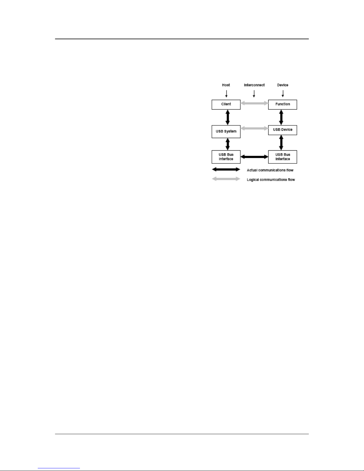
Spinpoint M9TU-USB 3.0 Product Manual REV 1.0
23
USB INTERFACE AND USB COMMANDS
CHAPTER 6 USB INTERFACE AND USB COMMANDS
6.1 Introduction
A Seagate disk drive with an Embedded USB Interface
fully supports and enhances PC mass storage requirements.
The Seagate USB interface conforms to the USB 2.0 and
3.0 standards in Cabling, in Physical Signals, and in
Logical Programming schemes. The Seagate Embedded
USB controller joins the industry premiere VLSI
circuitry with ingenious programming skill that does
not compromise performance or reliability. Seagate
integrates and delivers the cutting edge in technology.
Seagate USB class disk drives are designed to relieve and
to enhance the I/O request processing function of system
drivers.
Figure 6-1 shows how USB Interface constructs.
Figure 6-1: Interlayer Communication Flow
Physical Interface Layer- The bottom layer is a bus interface that transmits and receives packets.
Protocol Layer - The middle layer handles routing data between the bus interface and various endpoints on the
device. An endpoint is the ultimate consumer or provider of data. It may be thought of as a source or sink for
data.
Data Transfer Layer - The top layer is the functionality provided by the serial bus device, for instance, a
mouse or ISDN interface.
6.2 Physical Interface
The physical interface of the USB is described in the mechanical and electrical specifications for the bus.
6.2.1 Mechanical Interface
This chapter provides the mechanical and electrical specifications for the cables, connectors, and cable
assemblies used to interconnect USB devices. The specification includes the dimensions, materials,
electrical, and reliability requirements. This chapter documents minimum requirements for the external
USB interconnect. Substitute material may be used as long as it meets these minimums.
6.2.1.1 Mechanical Overview
All devices have an upstream connection. Upstream and downstream connectors are not mechanically
interchangeable, thus eliminating illegal loopback connections at hubs. The cable has four conductors: a twisted
signal pair of standard gauge and a power pair in a range of permitted gauges. The connector is four- position,
with shielded housing, specified robustness, and ease of attach-detach characteristics.
The USB physical topology consists of connecting the downstream hub port to the upstream port of another
hub or to a device. The USB can operate at four speeds. Super-speed (5 Gb/s), High-speed (480 Mb/s) and
full-speed (12 Mb/s) require the use of a shielded cable with two power conductors and twisted pair signal
conductors. Low-speed (1.5 Mb/s) recommends, but does not require the use of a cable with twisted pair
signal conductors. The connectors are designed to be hot plugged.
 Loading...