


FCC ID : A3LSPI-2L10022500
ATTACHMENT E.
- USER MANUAL -
HCT CO., LTD.
SAN 136-1, AMI-RI, BUBAL-EUP, ICHEON-SI, KYOUNGKI-DO, 467-701, KOREA
TEL:+82 31 639 8517 FAX:+82 31 639 8525 www.hct.co.kr
Report No. : HCTR1003FR17 1/1
EPBD-002040
Ed. 00
Mobile WiMAX RAS SPI-2L10
System Description

COPYRIGHT
This manual is proprietary to SAMSUNG Electronics Co., Ltd. and is protected by copyright.
No information contained herein may be copied, translated, transcribed or duplicated for any commercial
purposes or disclosed to the third party in any form without the prior written consent of SAMSUNG Electronics
Co., Ltd.
TRADEMARKS
Product names mentioned in this manual may be trademarks and/or registered trademarks of their respective
companies.
This manual should be read and used as a guideline for properly installing and operating the product.
This manual may be changed for the system improvement, standardization and other technical reasons without prior
notice.
If you need updated manuals or have any questions concerning the contents of the manuals, contact our Document
Center at the following address or Web site:
Address: Document Center 3rd Floor Jeong-bo-tong-sin-dong. Dong-Suwon P.O. Box 105, 416, Maetan-3dong
Homepage: http://www.samsungdocs.com
©2010 SAMSUNG Electronics Co., Ltd. All rights reserved.
Yeongtong-gu, Suwon-si, Gyeonggi-do, Korea 442-600

INTRODUCTION
Purpose
This description describes the characteristics, functions and structures of the SPI-2L10,
which is the RAS of Mobile WiMAX.
Who Should Read This Manual
This description is intended for engineers who want to know the functions and structures of
the SPI-2L10 and the Mobile WiMAX equipment operators.
Mobile WiMAX RAS SPI-2L10 System Description
Document Content and Organization
This description is composed of five Chapters and an Abbreviation as follows:
CHAPTER 1. Overview of Mobile WiMAX System
y Mobile WiMAX System Introduction
y Components of Mobile WiMAX Network
CHAPTER 2. System Overview
y System Introduction
y Main functions
y Specifications
y Interface between the Systems
CHAPTER 3. System Structure
y Hardware Structure
y Software Structure
© SAMSUNG Electronics Co., Ltd.
I
INTRODUCTION
CHAPTER 4. Message Flow
y Call Processing Message Flow
y Bearer Message Flow
y Network Synchronization Message Flow
y Alarm Message Flow
y Loading Message Flow
y Operation and Maintenance Message Flow
CHAPTER 5. Additional Functions and Tools
Web-EMT
ABBREVIATION
Describes the acronyms used in this description.
Conventions
The following types of paragraphs contain special information that must be carefully read
and thoroughly understood. Such information may or may not be enclosed in a rectangular
box, separating it from the main text, but is always preceded by an icon and/or a bold title.
NOTE
Indicates additional information as a reference.
Revision History
EDITION DATE OF ISSUE REMARKS
00 01. 2010. First Edition
II
© SAMSUNG Electronics Co., Ltd.

Mobile WiMAX RAS SPI-2L10 System Description
TABLE OF CONTENTS
INTRODUCTION I
Purpose....................................................................................................................................... I
Who Should Read This Manual................................................................................................... I
Document Content and Organization .......................................................................................... I
Conventions................................................................................................................................ II
Revision History.......................................................................................................................... II
CHAPTER 1. Overview of Mobile WiMAX System 1-1
1.1 Introduction to Mobile WiMAX.............................................................................................. 1-1
1.2 Mobile WiMAX Network Configuration.................................................................................1-5
CHAPTER 2. System Overview 2-1
2.1 Introduction to System..........................................................................................................2-1
2.2 Main Functions ............................................................................... .......................................2-3
2.2.1 Physical Layer Processing Function........................................................................... 2-3
2.2.2 Call Processing Function............................................................................................2-5
2.2.3 IP Processing Functions.............................................................................................2-6
2.2.4 Maintenance Function ................................................................................................2-8
2.3 Specifications ......................................................................................................................2-13
2.4 Interface between Systems................................................................................................. 2-15
CHAPTER 3. System Structure 3-1
3.1 Hardware Structure............................................................................................................... 3-1
3.1.1 Detailed Structure and Functions................................................................................3-3
3.1.2 External Interface................................................. ....................................................... 3-7
3.2 Software Structure................................................................................................................. 3-9
3.2.1 Software Basic Structure............................................................................................. 3-9
3.2.2 Call Control (CC) Block..............................................................................................3-11
3.2.3 OAM Block................................................................................................................ 3-13
© SAMSUNG Electronics Co., Ltd.
III

TABLE OF CONTENTS
CHAPTER 4. Message Flow 4-1
4.1 Call Processing Message Flow.............................................................................................4-1
4.1.1 Initial Entry...................................................................................................................4-1
4.1.2 Authentication..............................................................................................................4-4
4.1.3 St ate T rans ition............................................................................................................4-7
4.1.4 Location Update............................................................. ...... .......... ..... ...... ..... ..... ......4-13
4.1.5 Paging.......................................................................................................................4-18
4.1.6 Handover......................................... ..........................................................................4-19
4.1.7 Disconnection....................................... .....................................................................4-24
4.2 Bearer Message Flow...........................................................................................................4-26
4.3 Network Synchronization Message Flow...........................................................................4-27
4.4 Alarm Signal Flow................................................................................................................4-28
4.5 Loading Message Flow........................................................................................................4-29
4.6 Operation and Maintenance Message Flow.......................................................................4-31
CHAPTER 5. Additional Functions and Tools 5-1
5.1 Web-EMT.................................................................................................................................5-1
ABBREVIATION I
A ~ D............................................................................................................................................I
E ~ L....................................................... ........... ..... ...... ..... ..... ..... ...... ..... ..... ..... ...... .....................II
M ~ R .........................................................................................................................................III
S ~ W........................................... ..... ..... ...... ..... ..... ...... ..... ..... ..... ...... ..... ..... ........... ................... IV
IV
© SAMSUNG Electronics Co., Ltd.

Mobile WiMAX RAS SPI-2L10 System Description/Ed.00
LIST OF FIGURES
Figure 1.1 Configuration of Mobile WiMAX System Functions (Based on Profile C).............. 1-3
Figure 1.2 Mobile WiMAX Network Configuration .................................................................. 1-5
Figure 2.1 Operating Networks Separately.............................................................................2-7
Figure 2.2 Structure of SPI-2L10 Interface........................................................................... 2-15
Figure 2.3 Protocol Stack between NEs............................................................................... 2-16
Figure 2.4 Protocol Stack between SPI-2L10 and WSM...................................................... 2-16
Figure 3.1 Appearance of the SPI-2L10 (External).................................................................3-1
Figure 3.2 Appearance of the SPI-2L10 (Internal).................................................................. 3-2
Figure 3.3 SPI-2L10 Block Diagram....................................................................................... 3-3
Figure 3.4 Detailed Structure of M2RU-2W............................................................................ 3-6
Figure 3.5 External Interface Layout Plan.............................................................................. 3-7
Figure 3.6 External Interface Configuration............................................................................ 3-7
Figure 3.7 Software Structure of SPI-2L10............................................................................. 3-9
Figure 3.8 CC Block Structure...............................................................................................3-11
Figure 3.9 OAM Software Structure......................................................................................3-13
Figure 3.10 Interface between OAM Blocks ......................................................................... 3-14
Figure 4.1 Initial Entry Procedure...........................................................................................4-2
Figure 4.2 Authentication Procedure (During Initial Entry) ..................................................... 4-4
Figure 4.3 Authentication Procedure (During Authenticator Relocation) ................................ 4-6
Figure 4.4 Awake Mode Æ Idle Mode State Transition Procedure (MS-Initiated)................... 4-7
Figure 4.5 Awake Mode Æ Idle Mode State Transition Procedure (Network-Initiated) ........... 4-8
Figure 4.6 Awake Mode Q Sleep Mode State Transition Procedure ...................................... 4-9
Figure 4.7 Idle Mode Æ Awake Mode State Transition Procedure (QCS) ............................ 4-10
Figure 4.8 Inter-RAS Location Update Procedure................ ...... ..... ..... ..... ...... ..... ..... ..... ...... 4-13
Figure 4.9 Inter-ACR Location Update Procedure (PMIP/CMIP)............... ...........................4-14
Figure 4.10 Inter-ACR Location Update Procedure (Simple IP)........................................... 4-16
Figure 4.11 Paging Procedure.............................................................................................. 4-18
Figure 4.12 Inter-RAS Handover Procedure......................................................................... 4-19
Figure 4.13 Inter-ASN Handover (ASN-Anchored Mobility)..................................................4-21
Figure 4.14 Inter-ASN Handover (CSN-Anchored Mobility).................................................. 4-23
Figure 4.15 Disconnection (Awake Mode)............................................................................4-24
Figure 4.16 Disconnection (Idle Mode)................................................................................. 4-25
Figure 5.17 Bearer Message Flow ....................................................................................... 4-26
Figure 4.18 Network Synchronization Flow of SPI-2L10......................................................4-27
© SAMSUNG Electronics Co., Ltd.
V

TABLE OF CONTENTS
Figure 4.19 Alarm Signal Flow of SPI-2L10..........................................................................4-28
Figure 4.20 Loading Message Flow........................................................................... ...........4-30
Figure 4.21 Operation and Maintenance Signal Flow...........................................................4-31
Figure 5.1 Web-EMT Interface................................................................................................5-1
VI
© SAMSUNG Electronics Co., Ltd.
Mobile WiMAX RAS SPI-2L10 System Description
CHAPTER 1. Overview of Mobile
WiMAX System
1.1 Introduction to Mobile WiMAX
The Mobile WiMAX system is the wireless network system that supports IEEE 802.16
base service. The IEEE 802.16 standard is the basis of Mobile WiMAX, and includes IEEE
Std 802.16-2004 defining fixed wireless internet access service and IEEE Std 802.16,
P802.16-2004/Cor/D3 defining the technologies supporting mobility, which include
handover, paging.
Mobile WiMAX Standard
In this description, the entire Mobile WiMAX standard is expressed IEEE 802.16.
The wireless LAN (Wireless Local Area Network, WLAN) can provide high speed data
services, but its radio wave is short and covers only small areas, and also gives limited user
mobility. It is difficult for WLAN to ensure Quality of Service (QoS) for data service.
On the contrary, the present mobile communication networks support the mobility of the
users, but the service charge and the cost of system operations are high due to the limited
wireless resources. To provide faster service in the existing mobile communication
networks, it requires a separate wireless communication technology such as High Speed
Packet Access (HSPA) for the data services.
Mobile WiMAX can, therefore, overcome the limitations of the WLAN and present mobile
communication networks, and accommodate only the advantages of the system.
Mobile WiMAX can ultimately provide the high speed wireless internet services with low
cost at any time and in anyplace.
Samsung Mobile WiMAX System provides high speed data services using the transmission
technology of Orthogonal Frequency Division Multiple Access (OFDMA) by the T ime
Division Duplex (TDD), and can give wider coverage compared to the existing WLAN.
The system performance and the capacity have been expanded by the high performance
hardware, and thus, it can easily give various functions and services to the users.
© SAMSUNG Electronics Co., Ltd.
1-1

CHAPTER 1. Overview of Mobile WiMAX System
Characteristics of the Mobile WiMAX System
The major characteristics of Mobile WiMAX system are listed below.
y High Compatibility and Cross-Interworking
The Mobile WiMAX system is based on IEEE 802.16 standard and complies with
Wave 2 Profile and ASN Profile C of the Mobile WiMAX Forum. Therefore, the
Mobile WiMAX system provides high compatibility and excellent cross-interworking.
y High Performance Module Structure
The Mobile W iM A X system has high pe rform a nce by usi n g hig h-pe rforma nce proce ss or
and provides the module structure that it is easy to upgrade hardware and software.
y High System Stability
The Mobile WiMAX system provides the redundancy structure for main modules to
ensure higher stability.
y Variant Advance RF and Antenna Solution Support
The Mobile WiMAX system supports Multiple Input Multiple Output (MIMO) and
applies the power amplifier to support wideband operation bandwidth.
y Evolution Possibility into Next Generation Networking
The Mobile WiMAX system complies with the structure of the Mobile WiMAX ASN
Profile C network and the ASN Profile C network composition is similar to the
network structure considered in 3GPP Long Term Evolution (LTE)/Service
Architecture Evolution (SAE). Therefore, the Mobile WiMA X system can easily
evolve into the next generation network.
y Maintenance Function with Strengthened Security
The Mobile WiMAX system provides the security function (SNMPv2c/SNMPv3, SSH,
FTP/SFTP and HTTPs) to all channels for operation and maintenance. The Mobile
WiMAX system provides the operator Authentication, Authorization and Accounting
(AAA) function to authenticate the operator and assign the right for system access and
stores the operation history in a log.
1-2
© SAMSUNG Electronics Co., Ltd.
Mobile WiMAX RAS SPI-2L10 System Description/Ed.00
Mobile WiMAX System Functions(ACR, RAS)
The Mobile WiMAX system consists of Radio Access Station (RAS), Access Control
Router (ACR) and Mobile WiMAX System Manager (WSM). RAS manages 802.16
Medium Access Control (MAC)/Physical Layer (PHY) function for Mobile Station (MS),
ACR manages various control functions and interworking function between Mobile
WiMAX ASN system and CSN syste m.
System Support Standards
Network Working Group (NWG) of Mobile WiMAX Forum defines the Mobile
WiMAX network as Access Service Network (ASN) and Connectivity Service
Network (CSN). RAS of Samsung is Base Station (BS) and ACR is ASN-GW
(Gateway) of ASN, respectively.
RAS and ACR are based on ASN Profile C and Wave 2 Profile defined in the
Mobile WiMAX Forum and the Wave 2 Profile contains Wave 1 Profile.
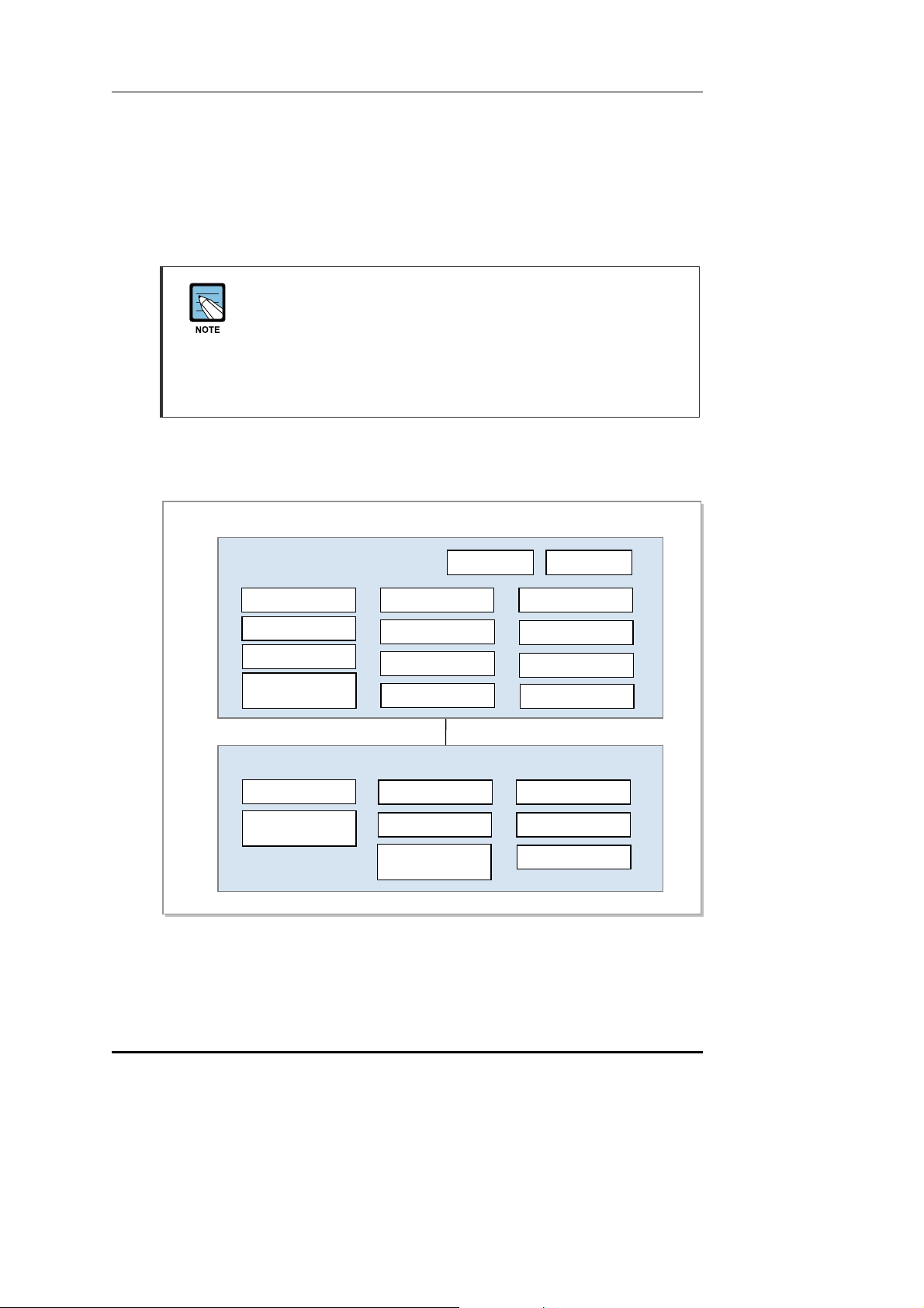
The figure below shows the functions of the ASN systems (ACR and RAS) based on
Profile C. Each block name complies with the standard of Mobile WiMAX NWG.
ASN
ASN-GW (ACR)
Paging Controller
Location Register
Context Function
Handover Function
(Handover Relay)
BS (RAS)
Context Function
Handover Function
(Handover Control)
Authenticator
Key Distributor
AAA Client
R6
Key Receiver
RRC & RRA
SFM
(Admission Control)
MIP FA PMIP client
SFA
IP Packet Forwarding
Header Compression
Packet Classification
DHCP relay agent
ARQ Operation
MAC PDU
Encapsulation/PHY
Figure 1.1 Configuration of Mobile WiMAX System Functions (Based on Profile C)
© SAMSUNG Electronics Co., Ltd.
1-3

CHAPTER 1. Overview of Mobile WiMAX System
The ACR supports the Convergence Sublayer (CS) and performs the packet classification
and Packet Header Suppression (PHS) functions. When the ACR carries out the header
compression function, it supports Robust Header Compression (ROHC) defined in the
NWG standard.
In addition, the ACR performs the paging controller and location register functions for an
MS in Idle Mode.
In authentication, the ACR performs the authenticator function and carries out the key
distributor function to manage the higher security key by interworking with the AAA server
as an AAA client. At this time, RAS performs the key receiver function to receive the
security key from the key distributor and manage it.
The ACR interworks with the AAA server of CSN for authentication and charging services
and with the HA of CSN for Mobile IP (MIP) service. The ACR as FA of MIP supports
Proxy MIP (PMIP).
The RAS performs the Service Flow Management (SFM) function to create/change/release
connections for each Service Flow (SF) and the admission control function while
creating/changing connections. In regard to the SFM function of the RAS, the ACR carries
out the SF Authentication (SFA) and SFID management functions. The ACR carries out the
SFA function to obtain the QoS information from Policy Function (PF) and apply it in the
SF creation and performs the SFID management function to create/change/release SFID
and map SF according to the packet classification.
In handover, the RAS performs the handover control function to determine the execution of
the handover and deal with corresponding handover signaling. The ACR confirms the
neighbor RAS list and relays the handover signaling message to the target system.
At this time, the ACR and the RAS carries out the context function to exchange the context
information between the target system and the serving system.
The RAS provides Admission Control to collect/manage the MS’s radio resource
information and the RAS’s own radio resource information (e.g., BSID). When load
balancing is required based on Admission Control results, it performs resource
management through FA overriding and BS init HO (Handover).
ASN System Function
For the detailed description about the system functions, refer to the system
description for each system provided by Samsung.
1-4
© SAMSUNG Electronics Co., Ltd.
Mobile WiMAX RAS SPI-2L10 System Description/Ed.00
A
g
A
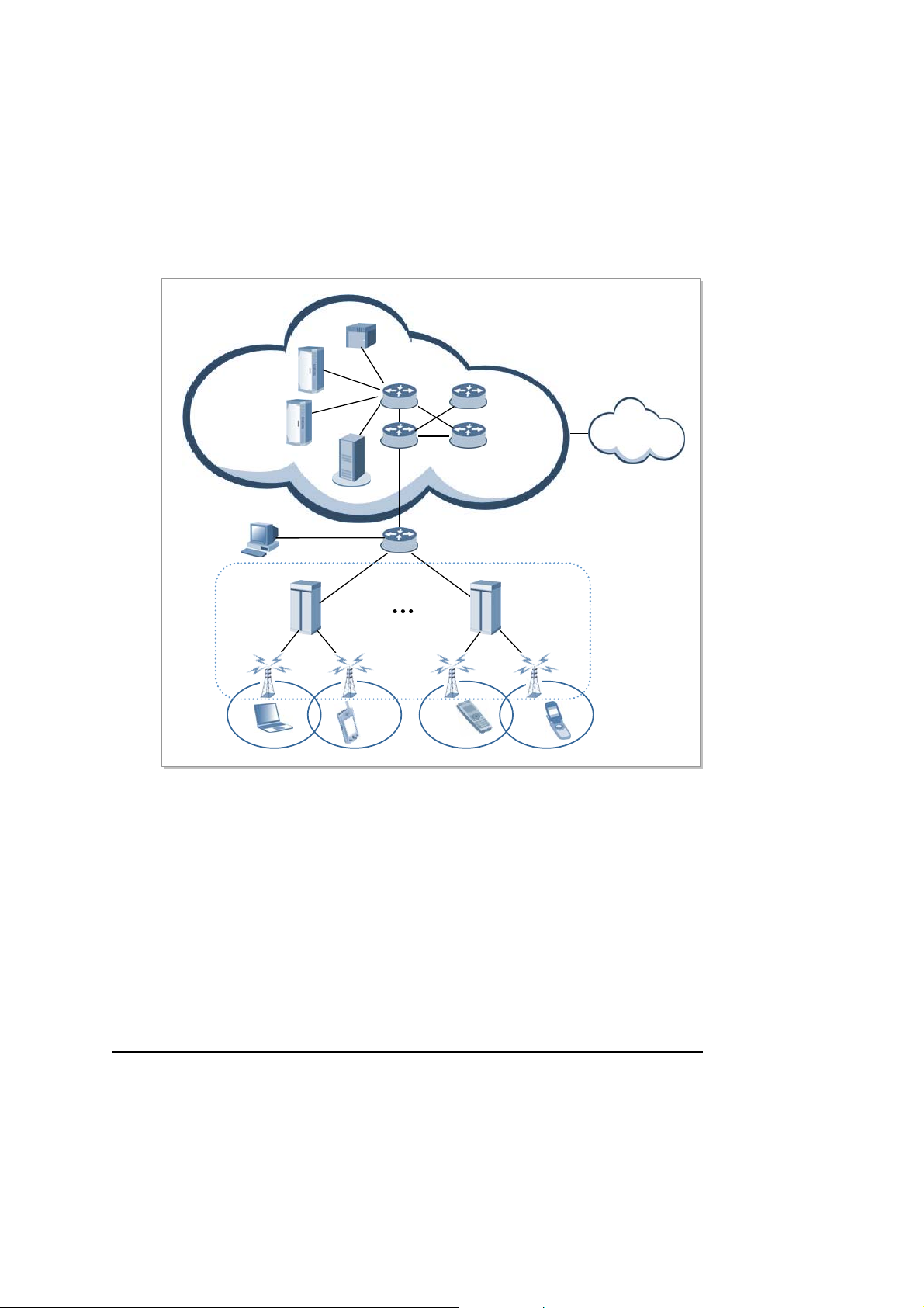
1.2 Mobile WiMAX Network Configuration
Mobile WiMAX network is composed of ASN and CSN. ACR and RAS are involved in
ASN and WSM is the Network Element (NE) to manage ACR and RAS. CSN is composed
of AAA server, HA and PCRF server. ASN is connected with CSN by router and switch.
The following diagram shows the composition of Mobile WiMAX network.
AAA
HA
DHCP
PCRF
WSM
ACR
RAS
MS
Figure 1.2 Mobile WiMAX Network Configuration
Core Router/Switch
CSN
e Router/Switch
Ed
CR
RAS
RAS
MS MS MS
Internet
SN
RAS
Radio Access Station (RAS)
RAS as the system between ACR and MS has the interface with ACR and provides the
wireless connection to MS under IEEE 8 0 2.16 s ta nda rds t o suppo rt wi re les s communication
service for subscrib ers .
RAS carries out wireless signal exchange with MS, modulation/demodulation signal
processing for packet traffic signal, efficient use of wireless resources, packet scheduling
for Quality of Service (QoS) assurance, assignment of wireless bandwidth, Automatic
Repeat request (ARQ) processing and ranging function. In addition, RAS controls the
connection for packet calls and handover.
© SAMSUNG Electronics Co., Ltd.
1-5

CHAPTER 1. Overview of Mobile WiMAX System
Access Control Router (ACR)
ACR, which is the system between CSN and RAS, enables several RASs to interwork with
IP network, sends/receives traffic between external network and MS, and controls QoS.
The ACR interfaces with the Authentication, Authorization and Accounting (AAA) server
using the Diameter/RADIUS protocols, and with the Policy & Charging Rules Function
(PCRF) server using the Diameter protocol. In this way, the ACR provides interfaces for
the NEs of the CSN.
Mobile WiMAX System Manager (WSM)
WSM provides the management environment for the operator to operate and maintain ACR
and RAS.
Home Agent (HA)
HA accesses other networks or private networks and enables Mobile IP (MIP) users to
access internet. HA interworks with ACR that performs Foreign Agent (FA) function for
Mobile IPv4 and interworks with MS to exchange data for Mobile IPv6.
Dynamic Host Configuration Protocol (DHCP) Server
The DHCP server allocates IP addresses to simple IP users. When an MS requests an IP
address allocation, the DHCP server allocates an IP address in interoperation with the ACR
that functions as the DHCP relay agent and sends it to the ACR.
Authorization, Authentication and Accounting (AAA) Server
AAA server interfaces with ACR and carries out subscriber authentication and accounting
functions. The AAA server interfaces with ACR via Diameter/RADIUS protocol and
provides Extensible Authentication Protocol (EAP) certification.
Policy & Charging Rules Function (PCRF) Server
The PCRF server is the server that manages the service policy and interfaces with ACR via
Diameter protocol. The PCRF server sends QoS setting information for each user session
and accounting rule information to ACR.
1-6
© SAMSUNG Electronics Co., Ltd.

Mobile WiMAX RAS SPI-2L10 System Description
CHAPTER 2. System Overview
2.1 Introduction to System
The SPI-2L10, RAS of Mobile WiMAX, is controlled by ACR and connects Mobile
WiMAX calls to MS.
The SPI-2L10 interfaces with MS via a wireless channel observing the Mobile WiMAX
standard (IEEE 802.16) and provides high-speed data service and multimedia service in
wireless broadband.
To this end, the SPI-2L10 provides the following functions: modulation/demodulation of
packet traffic signal, scheduling and radio bandwidth allocation to manage air resources
efficiently and ensure Quality of Service (QoS), Automatic Repeat request (ARQ)
processing, ranging function, connection control function to transmit the information on the
SPI-2L10 and set/hold/disconnect the packet call connection, handover control and ACR
interface function and system operation management function.
The SPI-2L10 interfaces with the ACR using the Fast Ethernet method, enabling various
control signals and traffic signals to be transmitted stably and quickly.
The SPI-2L10 can be installed in an outdoor environment and supports MIMO and a
capacity of 2Carrier/Omni per unit.
The SPI-2331 supports 10 MHz bandwidth per carrier and has a large packet service in
high speed. Other features are as follows.
Compact System
The SPI-2L10 is a single unit system that has a small system size and is lightweight.
Supporting Outdoor Environment
The SPI-2L10 is a system that can be operated in an outdoor environment. To operate
normally in an outdoor environment, it detects and controls the inside temperature of the
system and collects and reports the temperature-related alarms.
Because the SPI-2L10 uses a natural convection mechanism where no fan is used, it
tolerates an outdoor environment and has low power consumption.
© SAMSUNG Electronics Co., Ltd.
2-1

CHAPTER 2. System Overview
Convenience of Installation and Work
The SPI-2L10 can be installed on a wall or pole, or in a rack, and it can be also installed in
an outdoor environment, allowing the operator to take appropriate and flexible action for
various installation environments.
Supporting MIMO and Use of a High Output Power Amplifier
The SPI-2L10 supports the MIMO of 2TX/2RX RF paths to obtain diversity gains and
Spatial Multiplexing (SM) effects, increasing the data transfer rate. In addition, it supports
a maximum output of 4 W per antenna path and a maximum output of 8 W per system.
High Integrated System
The SPI-2L10 has a highly integrated modular structure optimized for the 2Carrier/Omni
system. It also has a small system size and is lightweight.
Protection of Software
The SPI-2L10 protects software and its configuration information using non-volatile
memory within the system.
Providing or not the System Feature and Schedule to Provide the System
Feature
For the providing or not the system feature and schedule to provide the features
described in this system description, see separate document.
2-2
© SAMSUNG Electronics Co., Ltd.

Mobile WiMAX RAS SPI-2L10 System Description/Ed.00
2.2 Main Functions
2.2.1 Physical Layer Processing Function
OFDMA Ranging
The ranging supported by the OFDMA system is roughly divided by the uplink timing
synchronization method and the contention based bandwidth request method.
y Uplink Timing Synchronization
In the uplink timing synchroniz ati on m ethod , the SPI-2L1 0 de t ec ts the tim ing e rro r of
the uplink signal by using the rang in g code t ransmitted from MS and transmits the
timing correction command to each MS to correct the transmission timing of the uplink.
The uplink timing synchroniza t i on met hod has in itia l ra ng ing, pe ri odic ra n ging,
handover ranging, etc.
y Contention Based Bandwidth Request
In the contention based bandwidth request method, the SPI-2L10 receives the
bandwidth request ranging code from each MS and allocates uplink resources to the
corresponding MS to enable to transmit the bandwidth request header. The contention
based bandwidth request method has bandwidth request ranging or something.
OFDMA Sub-carrier Allocation
The subchannelization is the process to tie the sub-carriers of OFDMA as a transmission
unit after grouping them by a certain rule. The SPI-2L10 performs the subchannelization to
mitigate the interference between cells.
The SPI-2L10 maps the column of the modulated downlink QAM symbol structure with
each sub-carrier and carries out the subchannelization when the column of the QAM
symbol structure is transmitted to the MS over the wireless line. In such way, the SPI-2L10
transmits the column of the QAM symbol structure to the MS via the sub-carriers pertained
to each subchannel.
DL/UL MAP Construction
The SPI-2L10 informs the air resources for the uplink and the downlink to the MS by using
DL/UL MAP. The DL/UL MAP consists of the scheduling information of the SPI-2L10 and
includes various control information for the MS.
Power Control
The SPI-2L10 carries out the power control function for the uplink signal received from
multiple MSs and then set the power intensity of the uplink signal to a specific level.
The SPI-2L10 transmits the power correction command to each MS and then makes the
MS power intensity be the level required in the SPI-2L10 when the MS transmits the
modulated uplink signal in a specific QAM modulation method.
© SAMSUNG Electronics Co., Ltd.
2-3

CHAPTER 2. System Overview
Hybrid-ARQ (H-ARQ) Operation
H-ARQ is the physical layer retransmission method using the stop-and-wait protocol.
The SPI-2L10 carries out the H-ARQ function to minimize the effect attending to the
change of wireless channel environment.
MIMO
The SPI-2L10 provides the MIMO function as follows according to Mobile WiMAX Wave
2 Profile:
y Downlink
− Matrix A (STC)
Transmission ratio of the Matrix A or STC is 1 and equal to that of Single Input
Single Output (SISO). However The Matrix A or the STC reduces the error of the
signal received from the MS by raising the stability of the signal received from the
MS by means of the Tx diversity. This technology is, also, effective in low Signal
to Noise Ratio (SNR) and provides excellent performance even when the MS
moves in high speed.
− Matrix B (SM, vertical encoding)
Matrix B or SM method raises the effectiveness of the frequency by raising the
transmission ratio in proportion to the number of antenna in comparison with SISO.
This technology is effective when the reception SNR is high.
y Uplink
− Collaborative SM
Collaborative SM is the technology that doubles the frequency efficiency in view
of the SPI-2L10 as two MSs with each individual antenna send data
simultaneously by using the same channel.
Adaptive MIMO Switching(SM/STC)
The SPI-2L10 provides the adaptive MIMO switching function which selects the SM or
STC method dynamically for the downlink MIMO function. The SPI-2L10 performs
switching based on a value calculated by reflecting the Carrier to Interference and Noise
Ratio (CINR) and transmission success rate sent by an MS.
2-4
© SAMSUNG Electronics Co., Ltd.

Mobile WiMAX RAS SPI-2L10 System Description/Ed.00
2.2.2 Call Processing Function
Cell Initialization Function
The SPI-2L10 announces the MAC Management message such as DCD/UCD/MOB_NBRADV to the cell area in service periodically to enable the MS receiving the message to
carry out the appropriate call processing function.
Call Control and Wireless Resource Allocation Function
The SPI-2L10 enables an MS to enter to or exit from the network. When an MS enters to or
exit from the network, the SPI-2L10 transmits/receives the signaling message required for
call processing via R1 interface with the MS or R6 interface with ACR.
The SPI-2L10 allocates various management/transport Connection Identifier (CID)
required for the network entry and service to an MS. When the MS exit from the network,
the SPI-2L10 collects and release the allocated CID.
Handover
The SPI-2L10 carries out the signaling and bearer processing for inter-sector HO
(Handover), inter-ACR HO and inter-carrier HO. At this time, ACR relays the handover
message between serving RAS and target RAS through the R6 interface.
Support of Sleep Mode
Sleep mode is defined in the IEEE 802.16 standard to save MS battery power. When the
MS transits to Sleep mode or the MS in Sleep mode returns to Awake mode, the SPI-2L10
sends and receives the required signaling messages to and from the MS and carries out the
corresponding call processing functions.
Admission Control (AC) Function
When receiving a call setup request, such as network entry, QCS (or network re-entry), or
handover request, from the MS, the SPI-2L10 carries out the admission control function
that monitors the CPU load, the traffic load and the number of users in Awake mode for
each subcell, and the number of service flows for each MS, subcell and QoS class to
prevent system overload and guarantee service quality.
MAC ARQ Function
The SPI-2L10 carries out the ARQ function of the MAC layer. In packet data exchange, the
transmission side transmits ARQ block which SDU is divided into, and retransmits the
packet according to the ARQ feedback information received from the reception side to
raise the reliability of data communication.
The SPI-2L10 carries out the following function for the service flows applying ARQ:
y MAC Management creation and transmission concerned with ARQ operation
y Feedback processing dependin g on ARQ types
y Block processing (fragmentation/reassemble/retransmission) depending on ARQ types
y ARQ timer/window management
© SAMSUNG Electronics Co., Ltd.
2-5

CHAPTER 2. System Overview
QoS Support Function
To maintain the QoS constraints given to each QoS class or service flow, the SPI-2L10
assigns a queue within the modem to each service flow and performs a scheduling
according to the priorities of those service flows. Because real-time traffic has a higher
priority than non-real-time traffic, a strict priority scheduling is used to schedule real-time
traffic first.
All real-time traffic is scheduled considering its transmission delay. All non-real-time
traffic is scheduled using the Proportional Fair (PF) scheduling considering efficiency and
fairness of air resources. The scheduled air resource assignment is sent to the MS using the
MAP. When receiving the MAP, the MS checks the air resources assigned to it and then
modulates or demodulates the downlink packets or sends the uplink packets to the assigned
uplink area.
Meanwhile, the SPI-2L10 can monitor the throughput statistics per service flow and the
Service Flow Addition (SFA) statistics per service flow, and provides the statistics for
admission control rejection.
2.2.3 IP Processing Functions
IP QoS Function
The SPI-2L10 supports 8-class DiffServ and mapping between the services classes of the
user traffic received from the MS and DiffServ classes. In addition, the SPI-2L10 supports
mapping between the Differentiated Services Code Points (DSCP) and the 802.3 Ethernet
MAC service classes.
However, to support the backhaul QoS function, the SPI-2L10n must interoperate with an
ACR that can support the function above.
Ethernet/VLAN Interface Function
The SPI-2L10 provides Ethernet interfaces and supports the Virtual Local Area Network
(VLAN) function and the Ethernet CoS function. Here, the MAC bridge function defined
in IEEE 802.1D is not supported.
The SPI-2L10 allows multiple VLAN IDs to be set for an Ethernet interface. To support
Ethernet CoS, it maps the DSCP value of the IP header to the CoS value of the Ethernet
header for Tx packets.
Operating Networks Separately
The SPI-2L10 allows configuration of two logical VLAN interfaces in a physical interface
to support the network operation method in which the network for common user traffic and
the network dedicated to management are separated. In this case, the IP address of each
VLAN interface must have a different subnet.
Of the two VLAN interfaces, one is used for management and the other is used for user
traffic. At this time, the SPI-2L10 provides the static routing table configuration function to
separate the traffic of two VLAN interfaces and control each traffic path.
When the network for common user traffic and the network dedicated to management are
not separated, no VLAN interface is used or only one VLAN interface can be used.
2-6
© SAMSUNG Electronics Co., Ltd.
Mobile WiMAX RAS SPI-2L10 System Description/Ed.00
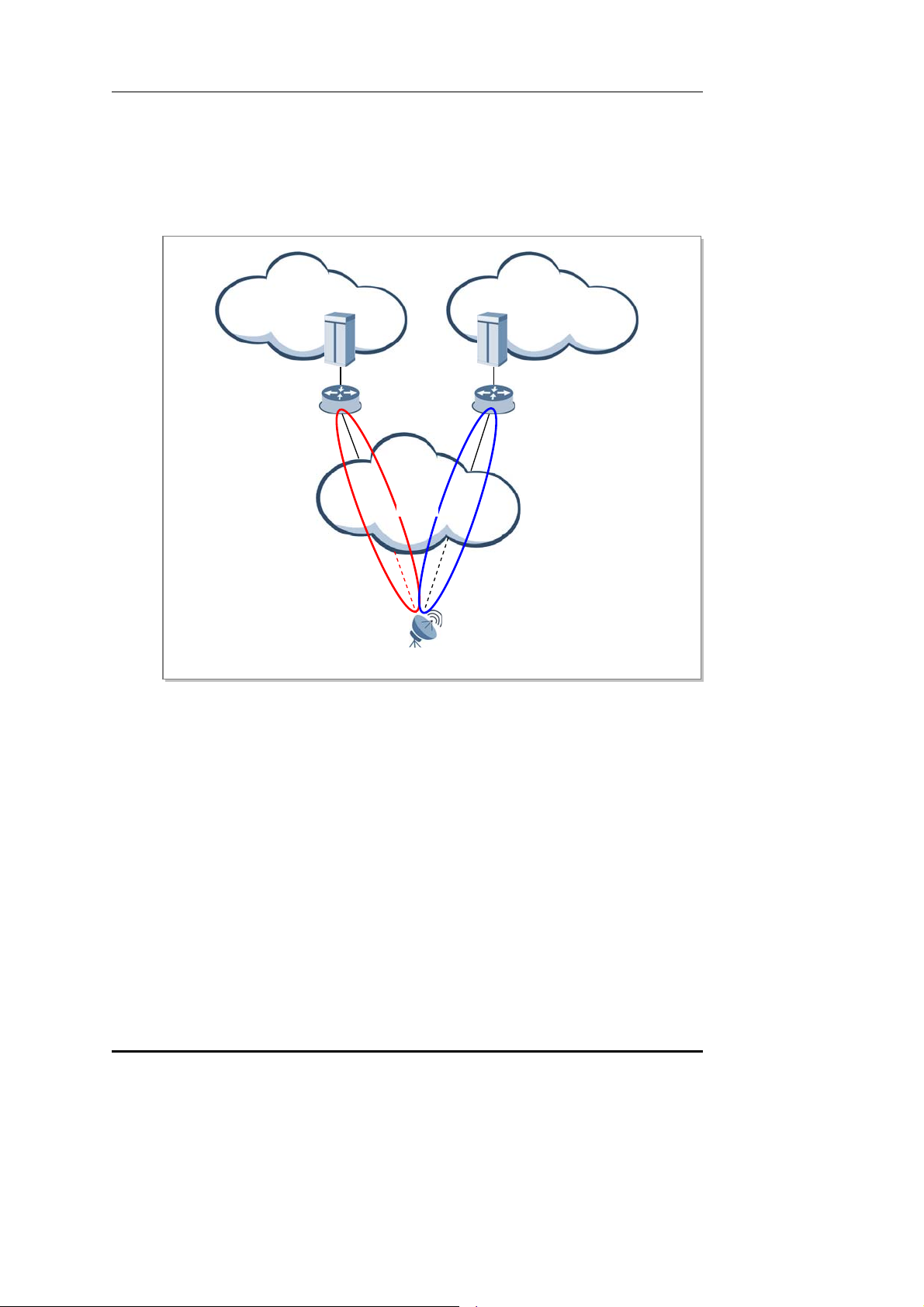
The following figure shows an example in which the network dedicated to management
and the user domain network are operated separately using the VLAN function of the SPI2L10. In the figure below, the SPI-2L10 is connected to the ASN using a physical link and
supports communication with the two logically separated networks using two VLAN
interfaces.
Network for management Network for user traffic
WSM ACR
router router
Access
Network
VLAN
Interface 1
RAS
Figure 2.1 Operating Networks Separately
VLAN
interface 2
Number of IP Addresses for a Backhaul Interface
The SPI-2L10 uses one IP address per carrier. Since the SPI-2L10 supports 2carrier, a total
of two IP addresses are needed. At this time, the IP addresses used by the two carriers
belong to a subnet.
The SPI-2L10 can operate the management network (OAM network) and the network for
user traffic separately. In this case, the SPI-2L10 requires one additional IP address for
interoperation with the WSM.
When the management network and t he ne tw ork for user traffic are not se pa ra te d from each
other, no additional IP address is needed. One of the two IP addresses used by the SPI-2L10
is used for interoperation with the WSM.
© SAMSUNG Electronics Co., Ltd.
2-7

CHAPTER 2. System Overview
IP Address
When the SPI-2L10 does not separate the management network from the
network for user traffic, no additional IP address is needed. One of the two basic
IP addresses is used for interoperation with the WSM.
2.2.4 Maintenance Function
The SPI-2L10 interworking with the management system carries out the following
maintenance functions: system initialization and restart, management for system
configuration, management for the operation parameters, failure and status management for
system resources and services, statistics management for system resources and various
performance data, diagnosis management for system resources and services and security
management for system access and operation.
Keepalive Monitoring for ACR and RAS
The SPI-2L10 monitors the keepalive status for the ACR to check whether the logical
backhaul line to the ACR is connected or disconnected. If this line is disconnected, the SPI2L10 blocks RF output and continues to monitor the up/down status for the ACR.
Then, if the SPI-2L10 receives a response message from the ACR again, it decides that the
backhaul line is reconnected and starts to send RF output normally.
Graphic and Text-based Console Interface
The Mobile WiMAX System Manager (WSM) manages all RASs using the Database
Management System (DBMS) and the SPI-2L10 interoperates with the WSM.
Moreover, the SPI-2L10 interoperates with the console terminal to allow the operator to
connect directly to the system and carry out the operation and maintenance functions.
The operator can use the graphics-based console interface (Web-EMT, Web-based Element
Maintenance Terminal) or the text-based console interface (IMISH, Integrated
Management Interface Shell) according to preferences and work purposes.
The operator can access the console interfaces without separate software. For the WebEMT, the operator can log in to the system using Internet Explorer. For the IMISH, the
operator can log in to the system using the Secure Shell (SSH) in the Command window.
However, for the Web-EMT, the operator can connect to the system only from a PC where
a Web-EMT license is installed and which is authenticated.
The operator can view and configure the configuration and operational information and
perform fault and status monitoring, and so on using the console terminal. However, the
operator can perform resource grow/degrow or change the major parameter values only
using the WSM.
2-8
© SAMSUNG Electronics Co., Ltd.

Mobile WiMAX RAS SPI-2L10 System Description/Ed.00
Interfacing with auxiliary devices
The SPI-2L10 supports the Ethernet interfaces (User Defined Ethernet (UDE)) f or
connecting the provider’s auxiliary devices (for example, an environment monitoring
device). The SPI-2L10 also provides traffic paths along which maintenance traffic can be
transmitted between the auxiliary devices and the remote auxiliary device monitoring
server.
For the packets received from an auxiliary device via the UDE port, the SPI-2L10
translates their source IP address (auxiliary device's private IP address Æ RAS’s public IP
address) and then sends them to the external auxiliary device monitoring server. For the
packets received from the external via the backhaul port and also destined to an auxiliary
device, the SPI-2L10 translates their destination IP addresses (RAS’s public IP address Æ
auxiliary device's private IP address) and sends them to the auxiliary device via the UDE
port. To accomplish this, the operator must set an NAT rule in the PI-2L10 and also must
configure IP address and port information in the auxiliary device monitoring server to make
it communicate with the specified auxiliary devices.
Only one UDE port can be used. The SPI-2L10 can interface with up to four auxiliary
devices. The bandwidth for an auxiliary device is limited within 128 kbps.
Operator Authentication Function
The SPI-2L10 provides the aut hentica ti on a nd t he permission management functions for the
operator who manages the Mobile WiMAX system. The operator accesses the SPI-2L10 by
using the operator’s ID a nd pa sswo rd via Web-EMT or IMISH and t he S PI-2L1 0 a ss ig ns t he
operation right in accordance with the operator’s level.
The SPI-2L10 carries out the logging function for access successes or failures and login
history, etc. This is not a function provided in interoperation with the authentication server
but a local authentication function of the RAS.
Maintenance Function with Enhanced Security Function
When communicating with the WSM, the SPI-2L10 supports S NM Pv2c a nd Sim ple Netw ork
Management Protocol version 3 (S NM Pv3), a nd FTP and SSH File Transfer Protocol (SF TP)
for security. When communicating with the console terminal, the SPI-2L10 supports Hyper
Text Transfer Protocol over SSL (HTTPs) and Secure Shell (SSH).
On-line Software Upgrade
When a software package is upgraded, the SPI-2L10 can upgrade the package while running
old version of software package. The package upgrade is progressed in t he fol lowing
procedure: ‘Add New Package Æ Change to Ne w packa ge Æ Delete Old Package’.
In package upgrade, the service is stopped temporarily because the old process is
terminated and the new process is started in the ‘Change to New package’ stage.
However, since OS is not restarted, the service will be provided again within a few minutes.
After upgrading software, the SPI-2L10 updates the package stored in a non-volatile storage.
In addition, the SPI-2L10 can re-perform the ‘Change to New package’ stage to roll back
into the previous package before upgrade.
© SAMSUNG Electronics Co., Ltd.
2-9

CHAPTER 2. System Overview
Call Trace Function
The SPI-2L10 supports the call trace function for a specific MS. The SPI-2L10 can carry
out the call trace function up to 10 MSs. If a call occurs in the MS that an operator
previously specified via ACR, the signaling message and statistical traffic data are
transmitted to WSM. Besides, the SPI-2L10, also, sends the RF environment information,
such as Carrier-to-Interference-and-Noise-Ratio (CINR) for MS, Modulation and Coding
Schemes (MCS) level and Burst Error Rate (BER).
Detailed Information for Each Session and Service Flow (PSMR/PSFMR)
The Mobile WiMAX system of Samsung collects and stores detailed information of all
sessions (Per Session Measurement Record, PSMR) and detailed information of all service
flows (Per Service Flow Measurement Record, PSFMR) to provide it to an external log
server. When a session or service flow is created, the Mobile WiMAX system starts to
collect relevant information, and when the session or service flow terminates, the system
creates and stores a message in a file so that the external log server can collect the message.
The information collected by the ACR includes session termination time, initial and final
handover information (handover types, cell information), and the MAC address and IP
address allocated to the MS. The SPI-2L10 collects such information as MS MAC
addresses, continued session time, continued service flow time, turnaround time for
network entry, CID, SFID, initial and final wireless quality information (RSSI, CINR, Tx
power), and throughput information.
The ACR deliver the information collected by ACR to the SPI-2L10, and the SPI-2L10
creates and stores a file for each period.
Threshold Cross Alert (TCA) Control
The SPI-2L10 defines under/over threshold for statistics. When a statistical value collected
at Bucket Interval (15, 30, and 60 minutes) is lower than the under threshold, it generates
an under TCA alarm . When the value is higher than the over threshold, it generates an over
TCA alarm. The alarms are reported to the WSM. TCA can enable or disable details of each
statistical group and set a threshold per severity.
IEEE 802.3ah
The SPI-2L10 provides IEEE 802.3ah Ethernet OAM for a backhaul interface.
Although IEEE 802.3ah OAM pertains the PHY layer, it is located in the MAC layer so
that it can be applied to all IEEE 802.3 PHYs. It creates or processes 802.3ah OAM frames
according to the functions defined in the specification.
Ethernet OAM continuously monitors the connection between links at each end, and also
monitors discovery , remote loopback, and error packets which deliver important link events
such as Dying Gasp. It also includes a link monitoring function which delivers event
notification in the event of threshold errors, and a variable retrieval function for 802.3ah
standard MIB.
The SPI-2L10 supports 802.3ah Ethernet OAM passive mode such as responding to
802.3ah OAM which is triggered in external active mode entities and loopback mode
operation, and sending event notification.
2-10
© SAMSUNG Electronics Co., Ltd.

Mobile WiMAX RAS SPI-2L10 System Description/Ed.00
Integrity Check
The SPI-2L10 proactively checks whether system configuration or operation information
(PLD) is in compliance with operator commands during system loading or operation, and
also checks whether system settings are OK and there is no problem with call processing.
If the result is not OK, it sends an alarm to the operator. That is, it checks whether system
configuration meets the minimum configuration conditions for call processing or whether
all operation information consists of valid values within an appropriate range. The result is
reported to the operator to help with correction of errors.
OAM Traffic Throttling
The SPI-2L10 provides a function that suppresses OAM related traffic which can occur in
the system depending on the operator command. The OAM related traffic includes fault
trap messages for alarm reports and statistics files that are created periodically.
In a fault trap, the operator can use an alarm inhibition command to suppress alarm
generation for all or some of system fault traps. This helps control alarm traffic.
In a statistics file, the operator can use commands for statistics collection configuration to
control the size of statistics file by disabling collection functions of each statistics group.
Throughput Test
The SPI-2L10 provides a throughput test for the backhaul to the ACR. The SPI-2L10
supports a server and client function for throughput tests.
The operator can set up target IP addresses, test duration, and bandwidths for throughput
tests, and check throughput and loss as test results. However, as the throughput test affects
system performance and call services, it is recommended not to perform the test during inservice.
System Log Control
The SPI-2L10 provides a log and log control function per application.
An application log can be created by an operator command or its debug level can be set.
The operator can usually keep the log function disabled, and when the log function is
necessary, he can change the debug level (Very Calm, Calm, Normal, Detail, Very Detail)
to enable logging and log save functions.
However, enabling log functions for many applications while the SPI-2L10 is running may
affect the system performance.
© SAMSUNG Electronics Co., Ltd.
2-11

CHAPTER 2. System Overview
Disabling Zero Code Suppression (ZCS)
The SPI-2L10 collects statistics data and generates statistics files periodically.
The WSM collects these statistics files. A statistics file is composed of the header used to
indicate a statistics group and its detailed index (for example, a specific carrier, sector, CPU,
port, etc.) and the statistics data for that index.
In a statistics period, the statistics data for a specific index can become zero in a statistics
file in the following cases:
y When the index does not actually exist in the configuration.
y When the index exists in the configuration but its statistics data collected during that
period is zero.
Therefore, the Disabling ZCS function, which sets the zero data flag in the sub index
header, is provided to recognize the two cases separately.
2-12
© SAMSUNG Electronics Co., Ltd.

Mobile WiMAX RAS SPI-2L10 System Description/Ed.00
2.3 Specifications
Capacity
The capacity of the SPI-2L10 is as follows:
Category System Capacity
Maximum Number of Carriers/Sectors 2 Carrier per RAS
Sector Omni
Backhaul Interface 1000 Base-LX 1 Port
RF Specification
The RF specifications of the SPI-2L10 is as follows:
Category Description
Operating Frequency 2,496~2,690 MHz
Channel Bandwidth 10 MHz
Output Reference for the port for system antenna interfacing
- 2 W + 2 W per Carrier @10
Unit Size and Weight
The table below lists the size and weight of the SPI-2L10.
Category Description
Size (W × H × D, mm) 335 × 450 × 180
Weight (kg) 25 or less
Input Power
The table below lists the power standard for the SPI-2L10.
Category Description
System Input Voltage -48 VDC
Power Consumption - Typical: 188 W (TBD)
- Max: 220 W (TBD)
* Condition: Based on room temperature, DL:UL=29:18
MHz
© SAMSUNG Electronics Co., Ltd.
2-13

CHAPTER 2. System Overview
Environmental Condition
The following table specifies the operating temperature, humidity, vibration, wind velocity
and waterproof ranges within which the SPI-2L10 can operate, as well as the strength of
the noise and electromagnetic interference produced during operation of the SPI-2L10.
Category Range Standard
Temperature -40~45˚C GR-487-CORE
Humidity 5~95% (Condensing up to 32˚C and not to ex ceed
Noise Acoustical Noise Suppression (Outdoor)
EMI
EMS/EMI Meets the standard. GR-1089-
Vibration Immunity - Earthquake: Zone4
Wind Immunity No damage when subject to winds in excess of 150 miles
Waterproof Meets IP55. IEC 60529
0.024 kg water/kg dry air)
- Under 65 dBA at a height of 1.0m and distance of 1.5m
- Measured point add: top roof
Meets class B.
- Office Vibration
: 5~100 Hz, 1g, 0.25 octave/minute
- Transportation Vibration
: 5~20 Hz: 0.01 g2/Hz
20~200 Hz: -3 dB/octave
per hour
Sec. 3.29
GR-487-CORE
Sec.3.34.2
GR-487-CORE
Sec.3.29
FCC Part 15
CORE
Section2, 3, 4
GR-63-CORE
Sec.4.4
GR-487-Core
3.30
2-14
© SAMSUNG Electronics Co., Ltd.
 Loading...